Abstract
Reactive power sharing in distributed generators (DGs) is one of the key issues in the control technologies of greenship microgrids. Reactive power imbalance in ship microgrids can cause instability and potential equipment damage. In order to improve the poor performance of the traditional adaptive droop control methods used in microgrids under high-load conditions and influenced by virtual impedance parameters, this paper proposes a novel strategy based on the deep reinforcement learning DQN-VI, in which a deep Q network (DQN) is combined with the virtual impedance (VI) method. Unlike traditional methods which may use static or heuristically adjusted VI parameters, the DQN-VI strategy employs deep reinforcement learning to dynamically optimize these parameters, enhancing the microgrid’s performance under varying conditions. The proposed DQN-VI strategy considers the current situation in greenships, wherein microgrids are generally equipped with cables of different lengths and measuring the impedance of each cable is challenging due to the lack of space. By modeling the control process as a Markov decision process, the observation space, action space, and reward function are designed. In addition, a deep neural network is used to estimate the Q function that describes the relationship between the state and the action. During the training of the DQN agent, the process is optimized step-by-step by observing the state and rewards of the system, thereby effectively improving the performance of the microgrids. The comparative simulation experiments verify the effectiveness and superiority of the proposed strategy.
1. Introduction
Addressing climate change has emerged as a universally acknowledged imperative within the global community. The International Maritime Organization (IMO) continues to strengthen regulatory measures targeting carbon emissions from ships [1]. Against this background, accelerating the development of greenships and achieving the green transformation of existing ships is a practical and feasible implementation plan for achieving energy conservation and emission reduction in the shipping industry [2]. Greenships meet the requirements of sustainable development by using various technologies that reduce atmospheric emissions, fuel consumption, and the production of environmentally harmful substances.
With the development of greenships, many new types of clean energy, such as photovoltaic and fuel cells, are gradually being used in conjunction with power battery packs. Although these new types of energy are clean and environmentally friendly, their random and intermittent nature poses new challenges for energy management [3]. For this reason, ship microgrid technology has emerged, coordinating various DGs to efficiently use new energy and becoming a key technology for greenships [4]. However, since traditional centralized control is difficult to deal with the complex ship microgrid, distributed control technology has become the research focus. Droop control achieves autonomous power distribution among distributed power sources by adjusting the voltage and frequency without a complex communication network. Droop control is particularly suitable for marine microgrid environments.
The droop-controlled inverter does not need to obtain information from other inverters connected in parallel to the ship’s power grid [5]. It only needs to detect the active and reactive power of its own output and then adjust the voltage amplitude and frequency of its own output to achieve stable operation of the entire ship’s microgrid system [6]. However, ship power grids often use medium and low voltage, and the line impedance mainly exhibits its resistive characteristics, which is unsuitable for the droop relationship obtained by treating the line impedance as approximately purely inductive, as in traditional droop control [7]. Existing solutions mostly use the virtual impedance method, which introduces a virtual inductive reactance at the control level to cancel the coupling of active and reactive power in the line impedance so that the line impedance of the DGs appears to be inductive [8,9].
Virtual impedance effectively solves the problem of droop control in non-purely inductive circuits. However, due to the space constraints of ships, the lengths of the cables connecting the various micro-power supplies in their power grids vary greatly, which can result in large differences in cable impedance. In this case, the reactive impedance is corrected using virtual impedance. Although the reactive part can be added by adding a large “inductor”, the resistance characteristics cannot be accurately compensated due to the different lengths of the cables connecting the micro-power supplies, resulting in difficulties in the distribution of reactive power, reactive circulation between inverters, and instability of the ship’s power grid [10]. Currently, there is no reliable method to estimate virtual impedance, which restricts the system’s ability to adapt effectively to changes in the distribution of DGs and intensifies reactive power circulation. The resulting excessive circulation can damage the DG units and shorten their service life.
Various strategies have been explored to enhance reactive power distribution and minimize circulating currents among DGs. In [11], a method combining virtual impedance and coupled compensation was proposed. While this approach demonstrably improved reactive power distribution and reduced circulating currents, it induced a voltage drop in the grid, thereby limiting its practical applicability. In [12], a harmonic virtual impedance design was introduced to optimize reactive power distribution and enhance power quality by managing harmonic distortion between DGs. While effective in addressing harmonics, this method primarily targeted power quality improvements related to harmonic content. Moreover, recent advancements in control strategies such as model-predictive control and fractional-order controllers [13,14,15] have highlighted their effectiveness in specific applications, yet they may face challenges in adapting to dynamic microgrid environments or achieving robust performance across diverse configurations. Furthermore, a reinforcement Q learning algorithm was utilized to address the issue of uneven reactive power distribution in microgrids with a high penetration of photovoltaic generation [16]. Although promising, this approach primarily focuses on photovoltaic-dominated systems, and its broader applicability to diverse microgrid configurations warrants further investigation. The reinforcement learning algorithm is used to learn the reactive power deviation between each DG and adjust the droop coefficient of each inverter to achieve the effect of equal reactive power distribution. Although it effectively reduces the reactive power deviation, the effect of power equalization achieved by the method proposed in this paper can be further improved [8]. Although there are many studies in the literature on using virtual impedance methods to solve the problem of reactive power distribution of DGs, further research is needed on how to assign the optimal value of the corresponding virtual impedance for each inverter. With the development of artificial intelligence, researchers have begun to apply reinforcement learning to control reactive power distribution of DGs in ship AC microgrids.
This paper extends prior research on reactive power distribution within ship microgrids by introducing an adaptive virtual impedance droop control strategy utilizing deep Q learning (DQN). The proposed method employs a neural network to learn the relationship between system states and control actions in complex microgrid environments, thus addressing the constraints of conventional Q tables. A real-time interaction is established between an agent and the ship’s microgrid, enabling the collection of reactive power distribution data from each distributed generator (DG). The virtual impedance is then dynamically adjusted based on the discrepancy between actual and desired reactive power levels. Simulation results confirm that this strategy substantially improves reactive power sharing among parallel-connected DGs. Therefore, the key contributions of this research are the following:
- 1.
- Integration of Deep Learning and Reinforcement Learning: Combining these techniques facilitates adaptive control within intricate microgrid settings.
- 2.
- Development of an Adaptive Virtual Impedance Droop Control Strategy: This strategy dynamically modifies the virtual impedance according to reactive power deviations, leading to enhanced reactive power distribution.
- 3.
- Comprehensive Simulation Validation: The simulations demonstrate the proposed strategy’s superior performance in improving reactive power sharing among DGs.
This article’s structure is as follows: Section 2 provides a review of conventional droop control strategies for ship AC microgrids, examining both the basic droop control principle and the adaptive approach based on virtual impedance (VI). Section 3 outlines the proposed intelligent control strategy, which is based on deep Q learning (DQN). This section details the general DQN framework for ship microgrids, the design of the droop control strategy (DQN-VI), and the training and optimization process for the DQN agent. Section 4 presents the simulation analysis, and Section 5 concludes this paper.
2. Conventional Droop Control Strategy for Ship AC Microgrids
2.1. Conventional Droop Control Principle
For a ship AC microgrid with two DG inverters connected to the ship’s grid, the equivalent circuit of the inverter single-phase output is shown in Figure 1 [17].
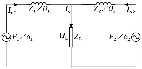
Figure 1.
Equivalent circuit of inverter single-phase output.
The equivalent circuit of the inverter single-phase output consists of two inverter units equivalent to voltage sources, line impedance, and a load [18], where , denotes the single-phase output voltage of the inverter , whose output impedance is , and is the output current phasor, is the current phasor of the load, the impedance of the load is , and the voltage phasor across the load is [19]. Real power and reactive power of the output can be given by the following:
Then, can be given by the following:
Substituting the above into Equation (1), we obtain the following:
When the line impedance is inductive, the following holds true [11]:
If the inverter uses the droop characteristics of and , Equation (3) can be simplified as follows:
The corresponding expressions for the droop characteristics of and can be expressed as follows:
where is the rated frequency when the DG is unloaded, is the voltage when the DG is unloaded, is the frequency droop coefficient, is the voltage droop coefficient, and is the actual frequency [20].
In Figure 2, is the line impedance current of the inverter , and is the voltage of its output filter capacitor. The reference voltage generation loop obtains the reference voltage reference signals and , while the voltage control loop obtains the drive signal that controls the inverter switching device.
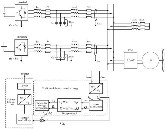
Figure 2.
Block diagram of the ship microgrid control structure based on conventional droop control strategy.
2.2. Adaptive Droop Control Strategy Based on Virtual Impedance (VI)
Within ship microgrids, frequency behaves as a global variable [21,22]. Consequently, using the active droop coefficient from the traditional droop control method (Equation (6)) [23] allows for a proportional allocation of active power. Voltage, however, acts as a local variable. Variations in cable length between each distributed generator (DG) and the point of common coupling (PCC) lead to differing line impedances. This discrepancy ultimately causes an uneven distribution of reactive power among the DGs.
In the circuit shown in Figure 1, two DG inverters in parallel operation have the following relationship:
where represents the voltage of the PCC, and represents the impedance of the line connecting the DGs to the microgrid. Assuming that the line impedance of is less than that of , . Then, the output terminal voltage of with high line impedance is larger than another; then, . It is assumed that
where is the additional line impedance of with respect to . Therefore, the voltage drop across the virtual impedance must be equal to the voltage drop across [24,25,26], which is related by the following equation:
where is the voltage drop across the resistive part of the DG output power through the , and is the voltage drop across the of the DGs. The voltage drop across the virtual impedance caused by DGs must be equal to the voltage drop across the additional line impedance . The process is as follows:
where the resistive part of the virtual impedance is represented by and its reactive part by ; the reactive part of the additional line impedance is represented by and its resistive part by . The line impedance of the substitution into Equation (6) is compensated for the , and the single-phase output voltage of the inverter can be given by the following:
where the voltage at the PCC point is denoted as , which is reduced due to the decrease in the voltage on the virtual impedance [27].
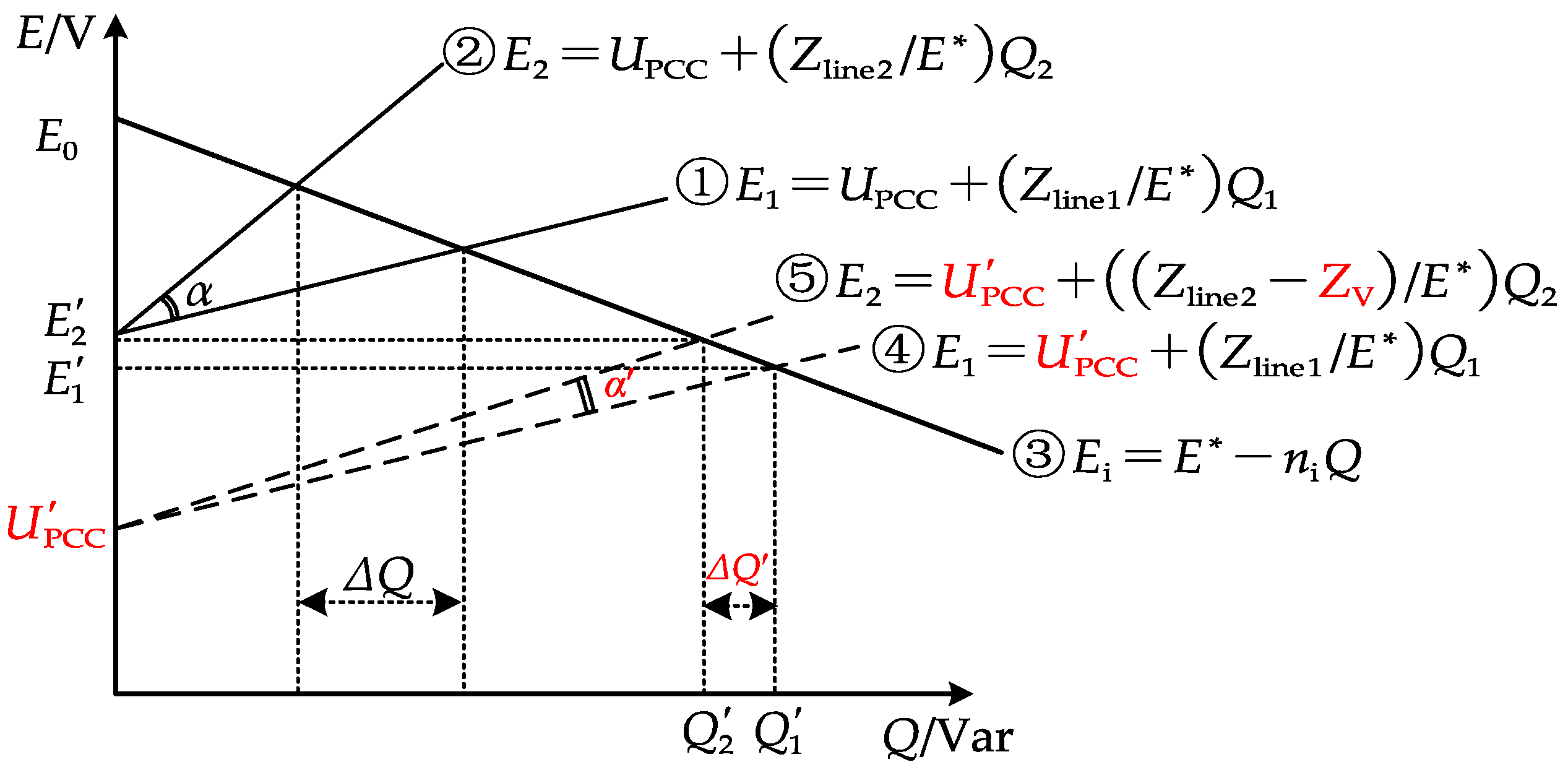
Therefore, the overall impedance characteristic curve of the two DG lines is shifted downward as a whole. The original output of more reactive power maintains the same slope (still maintaining ), while introduces virtual impedance to reduce its slope ().
As can be seen from Figure 3, is the angle between the overall reactive power distribution curves of the two DGs before the addition of the virtual impedance curve and curve [28]; is the difference in their reactive power; is the new angle between the new reactive power distribution curves and curve of the two DGs after the addition of the virtual impedance; finally, is the difference in their reactive power [29,30]. A certain virtual impedance voltage drop is included, which causes the change of curve to curve and the change of curve to curve . Therefore, according to Figure 3, the following relationship can be given:
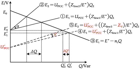
Figure 3.
Reactive power distribution using adaptive droop control with virtual impedance (VI).
The control system repeatedly executes the above adjustment process, gradually reducing the angle between the reactive power distribution curves of the two DGs and continuously reducing the reactive power deviation until achieving complete balance.
Droop control is widely used in microgrid control because it is simple to distribute power effectively. However, due to the different cable lengths of each DG connected to the power grid and the large difference in the line impedance of the electrical system, it is difficult to evenly distribute the reactive power of each DG, resulting in circulation between DGs and affecting their service life. This problem is more prominent in the ship environment with limited space. When a ship is navigating in the high seas, far from land, ensuring the safety of the ship’s power distribution system is essential. Therefore, by introducing virtual impedance, the problem caused by impedance differences can be solved while retaining the advantages of the droop control, and the accurate reactive power distribution of DG on ship microgrids can be realized.
3. Intelligent Control Strategy for Ship Microgrids Based on DQN
3.1. General Framework of Intelligent DQN-Based Control of Ship Microgrids
Due to the limited space of the ship’s power grid, the length of the cable varies greatly, resulting in significant differences in the line impedance of each access to the ship’s distribution network, thus affecting the sharing of reactive power. The adaptive droop control strategy based on virtual impedance proposed in Section 2.2 improves the distribution of reactive power by introducing virtual impedance to compensate for line impedance differences. However, this method still has limitations when applied to ship power grids characterized by a high load density. These limitations stem primarily from the inability to automatically adjust control parameters in real time based on actual conditions, thereby hindering effective responses to changing operating conditions.
In order to further improve the flexibility and accuracy of adaptive droop control, this paper introduces an improved strategy of ship microgrid intelligent control based on DQN. Through the addition of DQN agents, the control strategy can adjust the control parameters in real time to better cope with load changes and achieve more accurate reactive power distribution. Next, this framework and its working principle will be introduced in detail, as shown in Figure 4.
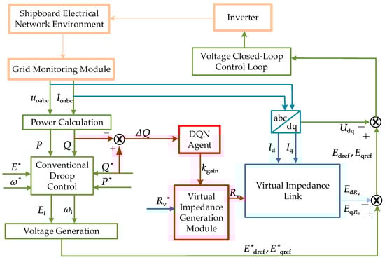
Figure 4.
Schematic diagram of the droop control strategy using the deep Q network-integrated virtual impedance (DQN-VI).
Figure 4 illustrates a modular design. The green section represents the conventional droop control component, where the relationship between reference voltage setpoints and is derived from droop tracking. The blue section depicts the adaptive droop control approach, which utilizes virtual impedance. By incorporating a specified virtual impedance value , a virtual impedance voltage drop of and is generated. This compensates for the voltage drop caused by the additional line impedance [31,32].
The red module highlights an adaptive droop control strategy employing DQN-VI. This agent monitors the reactive power deviation of the DG. Real-time correction of the virtual impedance is achieved by dynamically adjusting the virtual impedance gain . This module enhances the reactive power distribution within the ship’s microgrid.
3.2. Design of Droop Control Strategy Based on DQN-VI
In order to cope with the ship’s power grid with a high load density, this paper proposes the DQN-VI droop control strategy. This strategy dynamically adjusts the virtual impedance by monitoring the operating status of each DG on the ship’s electrical network in real time and calculating the power deviation, thereby achieving the precise distribution of reactive power. The design idea of the proposed control strategy is shown in Figure 5.
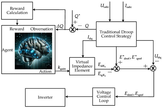
Figure 5.
The principle block diagram of the deep Q network-integrated virtual impedance (DQN-VI) strategy.
First, the output voltage and output current of the real-time monitoring DGs are used to calculate the active power and reactive power according to Equation (1). The calculated actual reactive power is compared with the given reactive power to obtain the reactive power deviation . This is used as an observation value by the agent, and the output action of the agent is the gain value of the virtual impedance. is applied to to correct it. With the corrected , then passes through the virtual impedance link in Figure 6.
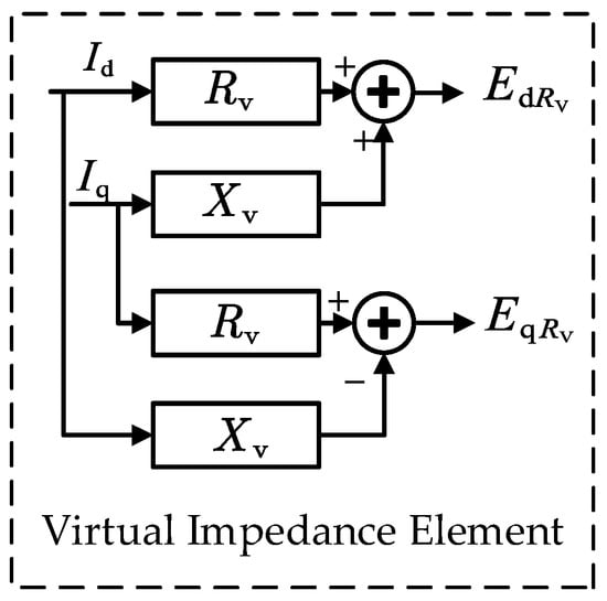
Figure 6.
Virtual impedance element structure diagram.
In this way, each time the agent performs an action, i.e., adjusts the virtual impedance gain , it will be rewarded according to the observed after the adjustment. The reward function is thus designed based on the reduction in the reactive power deviation . When decreases, the agent receives a positive reward, and vice versa. The learning goal of the agent is to maximize the long-term cumulative reward, so as to learn the optimal control strategy. Therefore, when the agent adjusts the action, it does not always use the current optimal action, but in some cases, the agent will randomly select different action values to explore the observation effect.
After training, the agent uses the learned Q function to select the best virtual impedance gain based on the observed to obtain the best virtual impedance amplitude. The optimal virtual impedance amplitude is added to the control loop to compensate to obtain a better control of the inverter output voltage . The DQN-VI strategy continuously feeds back and adjusts the output of the DQN agent according to the real-time output of the inverter. Through this strategy, the ship microgrid with a high load rate can ensure more accurate reactive power distribution among DGs.
3.3. Training and Optimization Process of the DQN Agent
The DQN agent needs to be trained in advance before it can be used in the control strategy in Figure 5. Therefore, this section details the training and optimization process of the DQN agent, as shown in Algorithm 1.
| Algorithm 1: DQN-based VI droop control strategy |
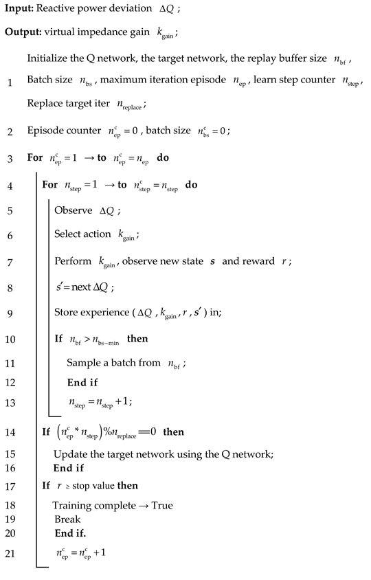 |
First, two neural networks with identical structures are initialized: the network and the target network . Here, is the Q network used for learning, and is the target network, with and representing the weight parameters of the two networks, respectively. indicates the agent’s current state, i.e., the reactive power deviation currently output by DGs; indicates the current output of the agent; the virtual impedance gain is . The Q network is used to estimate the value of each possible action. In contrast, the target network stabilizes the training process and reduces the volatility in the Q estimation. Here, the network parameters are initialized at random, and an experience replay pool is also created to store the experience data generated when the agent interacts with the environment.
During training, the DQN agent first obtains the reactive power deviation information processed by the real-time monitor of the ship’s power grid as the observation state of the DQN agent. After the agent performs , the reward value is calculated based on the changed feedback state. The reward function is established as the agent observation and reward mechanism. The reward function is as follows:
where is the reward value; μ, β, λ, and γ are auxiliary parameters used to adjust the response speed, sensitivity, and reward interval, respectively. The reward function is designed to guide the agent in the direction of reducing the power deviation.
The agent uses the strategy to select actions at each time step. Most of the time, the agent will select the action that it currently estimates to be optimal, but it will also occasionally select actions at random in order to explore potentially better strategies. After performing the selected action, the ship microgrid environment will give feedback on the new state and instant reward. This experience (including state, action, reward, and new state) will be stored in the experience replay pool for subsequent training. Then,
where is the target for the current time step, is the reward received at time step t, is the discount factor, is the new state, and is the maximum of the Q value of all possible actions in the target network for the next state. The weight parameters of the Q network are gradually adjusted by calculating the loss, so that it more accurately approximates the optimal Q function.
Finally, in order to ensure that the agent can converge within a reasonable amount of time and avoid overtraining, there are two termination conditions:
where is the number of training rounds, with a maximum value limited to , is the accumulated reward value, and is the preset accumulated reward threshold. The training automatically terminates when the preset maximum number of training rounds, , is reached. Alternatively, the training can be terminated early when the cumulative reward exceeds a preset threshold , as the agent is considered to have learned an optimal control strategy. The setting of these two conditions enables the DQN algorithm proposed in this paper to effectively control the training time, improve training efficiency, and avoid overfitting while ensuring the performance of the control strategy.
Upon completion of training, the DQN agent employs the acquired Q function to determine the best action for each observed state, maximizing the cumulative reward. The virtual impedance-based droop control strategy is then adjusted according to the learned optimal virtual impedance gain. Consequently, the output voltage of the DG inverters is modified, leading to a precise distribution of reactive power among the DGs within the ship’s microgrid.
4. Simulation Analysis
4.1. DQN Agent Training Simulation Parameter Settings
Table 1 gives the hyperparameters of the DQN agent. During training, the agent randomly sampled four states at each step. After 16 iterations, the minimum batch size reached 64, which triggered the start of the training process. This sampling and training process repeated until convergence.

Table 1.
Hyperparameters used in DQN agent training.
Figure 7 shows the reward curve during training. The training process reached the maximum saturation reward after the 25th round and continued to train for 74 sets for a total of about 21 min. All training was performed on a laptop equipped with an Intel 12th-generation Core i7-12700H CPU with 14 cores and 32 GB of memory.
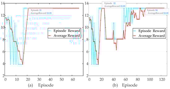
Figure 7.
Convergence analysis of DQN agent training with different learning rates: (a) learning rate and (b) learning rate .
To investigate the effect of the learning rate on the convergence behavior of our DQN-VI strategy, we compared two different values, and . As illustrated in Figure 7, the episode reward and average reward curves highlighted that a lower learning rate could result in slower initial convergence but more stable performance, whereas a higher learning rate sped up convergence but exhibited larger reward oscillations. This analysis underscored the importance of selecting an appropriate learning rate to balance training stability and convergence speed.
4.2. Evaluation Index of System Performance
In a ship’s power grid, due to frequent changes in load, the ship’s microgrid system requires accurate reactive power distribution from each DG to ensure power stability. In order to accurately evaluate the system’s performance in this environment, this section designs two main performance indicators to evaluate the accuracy and error of reactive power distribution: average error () and weighted mean square error (). is utilized to assess the reactive power distribution accuracy in the ship’s microgrid system by calculating the relative error between the actual and required reactive power at each time step. Its calculation formula is the following:
where represents the reactive power distribution of in the ship microgrid at time , represents the desired reactive power of at that moment, and represents the time points. This index can reflect the accuracy of the overall reactive power distribution of the ship microgrid system.
is specifically designed to address the distribution accuracy during critical periods. It highlights the reactive power distribution error during the operation of the ship’s microgrid through time weighting, reflecting the response capability of the ship’s microgrid system during critical periods. Its calculation formula is as follows:
where is the weight at time , which is the sum of two Gaussian distributions, emphasizing the error at a specific time period, defined as
where and denote the centers of the two Gaussian distributions, while and are the standard deviations which govern their width.
4.3. Simulation Analysis
In order to validate the effectiveness and superiority of the proposed strategy applied in the greenship microgrid, this study used Matlab/Simulink to build a ship microgrid simulation model. The established ship microgrid simulation model consisted of two DGs with the same parameters in parallel to the ship microgrid, except for the inconsistent line impedance. The specific simulation parameters of the input side of the ship’s microgrid are shown in Table 2.
Table 2.
Simulation parameters of the input side of the ship’s microgrid.
The ship microgrid simulation model adopted linear and non-linear loads, respectively. The adaptive VI droop control method, fuzzy adaptive VI droop control method, and DQN-VI droop control strategy were compared under each load type. Furthermore, we conducted harmonic distortion (THD) assessment of the output current of inverter #1 (Ioabc1) and the total output current (Iout) of all inverters, as depicted in Figure 8. This analysis supplemented our investigation into the effectiveness of the DQN-VI strategy in our shipboard microgrid system.
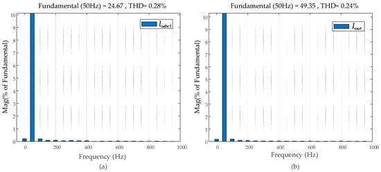
Figure 8.
Harmonic distortion assessment: (a) inverter #1 output current () and (b) total output current ().
4.3.1. Simulation Case 1
This study conducted simulation experiments on the operation of an inverter parallel network system with linear loads. The load of the parallel system consisted of three parts: was connected at 0 s and disconnected at 1.0 s; and subsequently took turns working for 1 s. Table 3 gives the load sizes and their corresponding states used in this simulation.
Table 3.
Linear load size of shiploads.
Figure 9 displays the active and reactive power curves over time, with clear shifts and noticeable spikes. There are sudden dips, particularly at 1.1–1.3 s and 2.1–2.2 s, suggesting that the system struggled with responsiveness. This aligns with the idea that traditional control has limitations, such as poor reaction to changes during high load and linear load switching, leading to imbalances in power distribution.
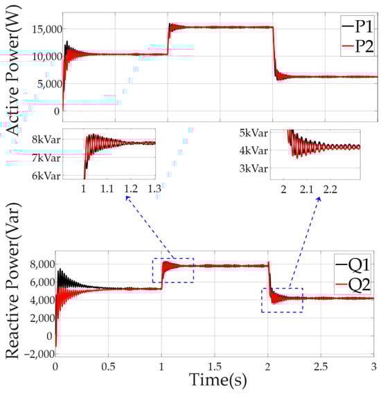
Figure 9.
Power distribution of each DG in the microgrid using the traditional adaptive virtual impedance droop control method facing linear loads of the ship.
Figure 10 demonstrates that the DG’s power distribution was managed using the fuzzy adaptive droop control method incorporating virtual impedance. On the other hand, Figure 10 shows active power with less pronounced changes compared to Figure 9, and reactive power variations appear better controlled. While both figures have fluctuations, Figure 10 seems to manage these more smoothly, likely due to the fuzzy logic adjusting virtual impedance dynamically. This suggests improved adaptability, especially during challenging load conditions.
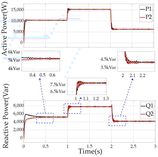
Figure 10.
Power distribution of each DG in the microgrid using the fuzzy adaptive virtual impedance (VI) droop control method facing linear loads of the ship.
Comparing Figure 10 and Figure 11, it can be seen that, using the droop control strategy of DQN-VI, the DQN agent was added to estimate a function that described the relationship between of the two DGs, and the existing virtual impedance was corrected in real time.
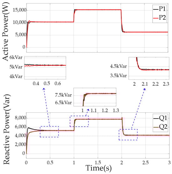
Figure 11.
Power distribution of each DG in the microgrid using the DQN-VI strategy facing linear loads of the ship.
The DQN-VI strategy greatly reduced the impact of line impedance differences on the ship microgrid system and significantly optimized the response performance of DG in the face of instantaneous changes in the linear load of the ship. In the face of 0 state response of , the response speed of the ship microgrid to DG reactive power distribution increased from 0.6 s to 0.5 s. When the linear load was switched from to and from to , the distribution pulsation of DG was greatly reduced.
4.3.2. Simulation Case 2
To further evaluate the proposed control strategy, a frequency converter and a propulsion motor were used as a non-linear load. The speed of the propulsion motor was regulated by the frequency converter, thereby modifying its operating condition. Table 4 shows the load size and corresponding state used in this simulation case.
Table 4.
Non-linear load size of shiploads.
The ship microgrid model was initially in a rated state. At 1.0 s, the motor was adjusted to the overload state by frequency conversion drive, and at 2.0 s, it was switched to a light-load state. Figure 12 exhibits significant power fluctuations and sudden drops, indicating its poor response to non-linear loads and imbalanced power allocation.
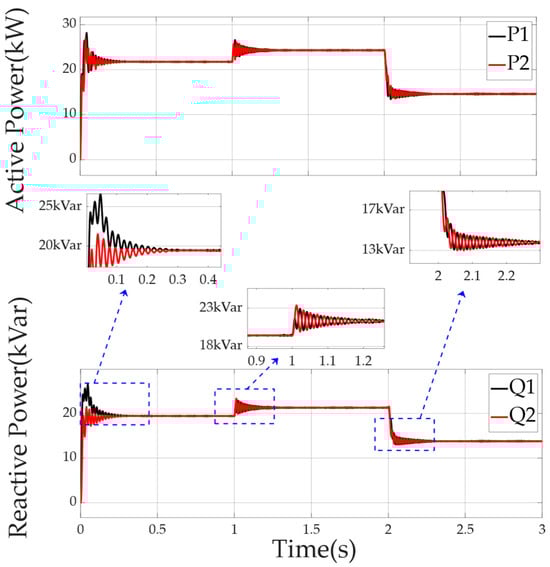
Figure 12.
Power distribution of each DG in the microgrid using the traditional adaptive virtual impedance (VI) droop control method facing non-linear loads on the ship.
Figure 13 shows reduced power fluctuations, with active power variations which are not pronounced and reactive power fluctuations which are better managed. This suggests that it is more capable of adapting to non-linear loads compared to the traditional adaptive virtual impedance droop control method.
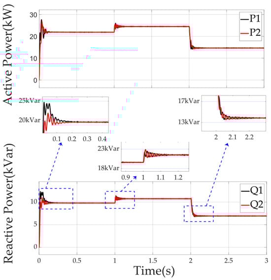
Figure 13.
Power distribution of each DG in the microgrid using the fuzzy adaptive virtual impedance (VI) droop control method facing non-linear loads on the ship.
Comparing Figure 13 and Figure 14, we can see that the droop control strategy using DQN-VI optimized the dynamic performance when facing the switching of ship non-linear load conditions. When the motor was accelerated from the rated state to the full-load state and from the full-load state to the light-load state, the response pulsation of the ship’s microgrid to the DG reactive power distribution was greatly reduced, and the response time was shortened from 0.2 s to 0.05 s.
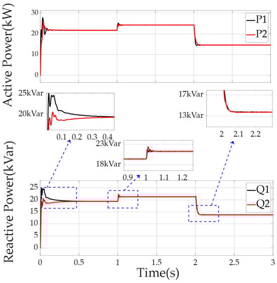
Figure 14.
Power distribution of each DG in the microgrid using the DQN-VI strategy facing non-linear loads of the ship.
The two evaluation indexes established in Section 4.2 were used to evaluate the reactive power deviation of the ship microgrid model in the steady state, as shown in Table 5.
Table 5.
The effect of different control strategies on the power distribution of shiploads.
When the shipload changed, the DQN-VI droop control strategy optimized the reactive power deviation. Comparing fuzzy adaptive VI and DQN-VI, we can see that, under the linear load, was reduced by 33%, and was reduced by 24%; under the non-linear load, was reduced by 17%, and was reduced by 35%. Through the independent simulation of these two load types, this study analyzed the performance of the improved DQN-VI droop control strategy compared to the VI adaptive droop control strategy under different load characteristics. The simulation results showed that the control strategy better coped with the changes in linear and non-linear loads and achieved more accurate distribution of the reactive power of DGs.
5. Conclusions
This paper mainly solves the problem of reactive power sharing in greenship microgrids. The traditional adaptive droop control method employed in microgrids has limitations under high-load conditions, and its performance significantly depends on virtual impedance parameters. To address these issues, this paper proposes the DQN-VI strategy using deep reinforcement learning. The strategy models the control process as a Markov decision process, which includes defining an observation space, an action space, and a reward function. The proposed method uses a deep neural network to estimate the Q function, which relates the system state to the corresponding actions. After training, the agent automatically adjusts the virtual impedance gain, reducing reactive power deviations and enhancing the performance of greenship microgrids. Comparative simulation experiments were conducted to validate the effectiveness and superiority of the proposed strategy in greenship microgrids. The simulation results demonstrate that the proposed DQN-VI droop control strategy optimizes reactive power deviation, achieving significant reductions in error metrics compared to fuzzy adaptive VI. Quantitatively, under linear loads, was reduced by 33%; under a non-linear load, was reduced by 35%.
Although this study demonstrates the effectiveness of the DQN-VI strategy through simulation, future work will include experimental validation on hardware platforms to confirm its practical performance. Moreover, extending this strategy to hybrid AC/DC microgrids provides an opportunity to explore its versatility in more complex power system configurations.
Author Contributions
Conceptualization, W.L. and H.Z.; methodology, W.L.; software, H.Z.; validation, J.Z.; formal analysis, T.Y.; investigation, W.L.; resources, W.L.; data curation, H.Z.; writing—original draft preparation, W.L.; writing—review and editing, W.L.; visualization, W.L., H.Z. and J.Z.; supervision, J.Z.; project administration, W.L.; and funding acquisition, T.Y. All authors have read and agreed to the published version of the manuscript.
Funding
This research was funded by the Natural Science Foundation of China (under grant no. 52401415).
Data Availability Statement
Data are contained within the article.
Conflicts of Interest
The authors declare no conflicts of interest. The funders had no role in the design of the study; in the collection, analyses, or interpretation of data; in the writing of the manuscript; or in the decision to publish the results.
References
- Badakhshan, S.; Senemmar, S.; Zhang, J. Dynamic Modeling and Reliable Operation of All-Electric Ships with Small Modular Reactors and Battery Energy Systems. In Proceedings of the 2023 IEEE Electric Ship Technologies Symposium (ESTS), Alexandria, VA, USA, 1–4 August 2023; pp. 327–332. [Google Scholar]
- Jin, Z.; Meng, L.; Guerrero, J.M.; Han, R. Hierarchical control design for a shipboard power system with DC distribution and energy storage aboard future more-electric ships. IEEE Trans. Ind. Inform. 2017, 14, 703–714. [Google Scholar]
- Han, Y.; Ning, X.; Yang, P.; Xu, L. Review of power sharing, voltage restoration and stabilization techniques in hierarchical controlled DC microgrids. IEEE Access 2019, 7, 149202–149223. [Google Scholar]
- Zhaoxia, X.; Tianli, Z.; Huaimin, L.; Guerrero, J.M.; Su, C.L.; Vásquez, J.C. Coordinated control of a hybrid-electric-ferry shipboard microgrid. IEEE Trans. Transp. Electrif. 2019, 5, 828–839. [Google Scholar]
- Li, Y.W.; Kao, C.N. An accurate power control strategy for power-electronics-interfaced distributed generation units operating in a low-voltage multibus microgrid. IEEE Trans. Power Electron. 2009, 24, 2977–2988. [Google Scholar]
- Sun, X.; Hao, Y.; Wu, Q.; Guo, X.; Wang, B. A multifunctional and wireless droop control for distributed energy storage units in islanded AC microgrid applications. IEEE Trans. Power Electron. 2016, 32, 736–751. [Google Scholar]
- Vu, T.V.; Paran, S.; El Mezyani, T.; Edrington, C.S. Real-time distributed power optimization in the DC microgrids of shipboard power systems. In Proceedings of the 2015 IEEE Electric Ship Technologies Symposium (ESTS), Old Town Alexandria, VA, USA, 21–24 June 2015; pp. 118–122. [Google Scholar]
- Mohammed, N.; Lashab, A.; Ciobotaru, M.; Guerrero, J.M. Accurate reactive power sharing strategy for droop-based islanded AC microgrids. IEEE Trans. Ind. Electron. 2022, 70, 2696–2707. [Google Scholar]
- Zhang, X.; Gong, L.; Zhang, Y.; Ma, X.; Han, L.; Jiang, S.; Zhou, W. A novel virtual inductor optimization methodology of virtual synchronous generators for enhanced power decoupling. Int. J. Electr. Power Energy Syst. 2025, 165, 110473. [Google Scholar]
- Liu, W.; Pei, J.; Ye, Y.; Liu, Y.; Bucknall, R.; Xu, D. Prescribed-performance-based adaptive fractional-order sliding mode control for ship DC microgrid. Ocean Eng. 2024, 311, 118885. [Google Scholar]
- Peng, Z.; Wang, J.; Bi, D.; Wen, Y.; Dai, Y.; Yin, X.; Shen, Z.J. Droop control strategy incorporating coupling compensation and virtual impedance for microgrid application. IEEE Trans. Energy Convers. 2019, 34, 277–291. [Google Scholar]
- Göthner, F.; Roldán-Pérez, J.; Torres-Olguin, R.E.; Midtgård, O.M. Harmonic virtual impedance design for optimal management of power quality in microgrids. IEEE Trans. Power Electron. 2021, 36, 10114–10126. [Google Scholar]
- Zaid, S.A.; Albalawi, H.; AbdelMeguid, H.; Alhmiedat, T.A.; Bakeer, A. Performance Improvement of H8 Transformerless Grid-Tied Inverter Using Model Predictive Control Considering a Weak Grid. Processes 2022, 10, 1243. [Google Scholar] [CrossRef]
- Zaid, S.A.; Bakeer, A.; Magdy, G.; Albalawi, H.; Kassem, A.M.; El-Shimy, M.E.; AbdelMeguid, H.; Manqarah, B. A New Intelligent Fractional-Order Load Frequency Control for Interconnected Modern Power Systems with Virtual Inertia Control. Fractal Fract. 2023, 7, 62. [Google Scholar] [CrossRef]
- Zaid, S.A.; Bakeer, A.; Albalawi, H.; Alatwi, A.M.; AbdelMeguid, H.; Kassem, A.M. Optimal Fractional-Order Controller for the Voltage Stability of a DC Microgrid Feeding an Electric Vehicle Charging Station. Fractal Fract. 2023, 7, 677. [Google Scholar] [CrossRef]
- Shi, J.; Zhang, C.; Wu, H.; Xuan, S.; Gao, L.; Shen, J. Q-learning method in reactive power sharing control of high-penetration photovoltaic micro-grids. J. Electr. Power Syst. Autom. 2021, 33, 88–93. [Google Scholar]
- Wunderlich, A.; Wong, A.; Cronin, J.; Santi, E. Novel Rate-Limited Droop Control for DC Distribution with Impulsive Loads. In Proceedings of the 2023 IEEE Electric Ship Technologies Symposium (ESTS), Alexandria, VA, USA, 1–4 August 2023; pp. 303–310. [Google Scholar]
- Han, Y. Modeling and Control of Power Electronic Converters for Microgrid Applications; Springer Nature: Berlin/Heidelberg, Germany, 2021. [Google Scholar]
- Li, Z.; Li, H.; Zheng, X.; Gao, M. Virtual model predictive control for virtual synchronous generators to achieve coordinated voltage unbalance compensation in islanded micro grids. Int. J. Electr. Power Energy Syst. 2023, 146, 108756. [Google Scholar]
- Mahmood, H.; Michaelson, D.; Jiang, J. Accurate reactive power sharing in an islanded microgrid using adaptive virtual impedances. IEEE Trans. Power Electron. 2014, 30, 1605–1617. [Google Scholar]
- Jiang, E.; Zhao, J.; Shi, Z.; Mi, Y.; Lin, S.; Muyeen, S.M. Intelligent Virtual Impedance Based Control to Enhance the Stability of Islanded Microgrid. J. Electr. Eng. Technol. 2023, 18, 3971–3984. [Google Scholar]
- Vijay, A.S.; Parth, N.; Doolla, S.; Chandorkar, M.C. An adaptive virtual impedance control for improving power sharing among inverters in islanded AC microgrids. IEEE Trans. Smart Grid 2021, 12, 2991–3003. [Google Scholar]
- Saimadhuri, K.Y.; Janaki, M. Advanced control strategies for microgrids: A review of droop control and virtual impedance techniques. Results Eng. 2024, 25, 103799. [Google Scholar]
- Li, S.; Tang, X.; Zheng, J.; Wang, C. Power Sharing Control Strategy of High-Frequency Chain Matrix Converter Parallel System Based on Adaptive Virtual Impedance. J. Phys. Conf. Ser. 2021, 2136, 012022. [Google Scholar]
- Chen, J.; Yue, D.; Dou, C.; Chen, L.; Weng, S.; Li, Y. A virtual complex impedance based droop method for parallel-connected inverters in low-voltage AC microgrids. IEEE Trans. Ind. Inform. 2020, 17, 1763–1773. [Google Scholar]
- Zhu, Y.; Zhuo, F.; Wang, F.; Liu, B.; Gou, R.; Zhao, Y. A virtual impedance optimization method for reactive power sharing in networked microgrid. IEEE Trans. Power Electron. 2015, 31, 2890–2904. [Google Scholar] [CrossRef]
- Wang, Y.; Kuang, Y.; Xu, Q. A current-limiting scheme for voltage-controlled inverter using instantaneous current to generate virtual impedance. IEEE J. Emerg. Sel. Top. Circuits Syst. 2023, 13, 524–535. [Google Scholar] [CrossRef]
- Wang, H.; Wang, X. Distributed reactive power control strategy based on adaptive virtual reactance. IET Renew. Power Gener. 2023, 17, 762–773. [Google Scholar] [CrossRef]
- Sharma, B.; Pankaj, P.K.; Terriche, Y.; Saim, A.; Shrestha, A.; Su, C.L.; Guerrero, J.M. Power sharing in three-level NPC inverter based three-phase four-wire islanding microgrids with unbalanced loads. IEEE Access 2023, 11, 20725–20740. [Google Scholar] [CrossRef]
- Daniel, A.; Dayalan, S. A simple network reduction technique for large autonomous microgrids incorporating an efficient reactive power sharing. Int. J. Emerg. Electr. Power Syst. 2022, 23, 161–170. [Google Scholar] [CrossRef]
- Vijay, A.S.; Doolla, S.; Chandorkar, M.C. Varying negative sequence virtual impedance adaptively for enhanced unbalanced power sharing among DGs in islanded AC microgrids. IEEE Trans. Energy Convers. 2021, 36, 3271–3281. [Google Scholar] [CrossRef]
- Pournazarian, B.; Seyedalipour, S.S.; Lehtonen, M.; Taheri, S.; Pouresmaeil, E. Virtual impedances optimization to enhance microgrid small-signal stability and reactive power sharing. IEEE Access 2020, 8, 139691–139705. [Google Scholar] [CrossRef]


Disclaimer/Publisher’s Note: The statements, opinions and data contained in all publications are solely those of the individual author(s) and contributor(s) and not of MDPI and/or the editor(s). MDPI and/or the editor(s) disclaim responsibility for any injury to people or property resulting from any ideas, methods, instructions or products referred to in the content. |
© 2025 by the authors. Licensee MDPI, Basel, Switzerland. This article is an open access article distributed under the terms and conditions of the Creative Commons Attribution (CC BY) license (https://creativecommons.org/licenses/by/4.0/).