Abstract
Space tracking ships are critical assets in modern space exploration, overcoming the limitations of land-based tracking systems by providing real-time telemetry, trajectory monitoring, and communication support for satellites and spacecraft. However, the existing literature offers limited insights into the historical development, technological evolution, and collaborative research trends of these specialized vessels. This study employs a bibliometric analysis using CiteSpace (6.3.R1) to identify research trends, highlight key technological advancements, and assess international collaboration. By analyzing publications from major contributors, including the United States, the former Soviet Union, France, and China, the paper reveals technological innovations such as advancements in measurement systems, communication technologies, and the integration of artificial intelligence (AI) for enhanced tracking precision. Structural and operational analyses emphasize the importance of design factors, including ship dimensions and internal systems, for ensuring optimal performance in challenging maritime environments. The findings highlight evolving technological priorities and persistent gaps in international collaboration, suggesting opportunities for global partnerships to advance the field. This study bridges historical and technical gaps, providing valuable insights for enhancing the efficiency and strategic relevance of space tracking ships in future space exploration missions.
1. Introduction
Space tracking ships, also known as missile range instrumentation ships, are vessels equipped with antennas and electronics designed to support the launch and tracking of missiles and spacecraft [1,2,3]. Effective launch support is critical for mission success, as it ensures that all systems are operational and that any issues can be addressed promptly [4,5]. The integration of tracking ships into this framework enhances the overall reliability and safety of space missions [6]. They are primarily used to gather telemetry data [7], provide communication links [8], and ensure safety during launches by monitoring the trajectory of the spacecraft [9]. The Yuanwang [10] series of space tracking ships, operated by the People’s Liberation Army of China, and the U.S. tracking ship Howard O. Lorenzen [11] are two of the world’s iconic space tracking ships.
In the era of advanced space exploration, the role of space tracking ships has become increasingly critical. These vessels are essential for monitoring [12] and supporting various space missions, including satellite launches, interplanetary explorations, and space station operations [13]. With the rise of commercial spaceflight and satellite launches, the demand for tracking ships has increased, leading to investments in new vessels and upgrades to existing ones that ensure the accurate tracking of spacecraft and the effective management of mission parameters [14].
Measurement and control technology encompasses a range of systems and methodologies designed to collect [15], analyze, and respond to data in real time [16,17]. This technology is vital for determining the position, velocity, and trajectory of spacecraft, as well as for ensuring the safety and success of missions [18,19,20,21]. Innovations in sensor technology [22,23], data processing algorithms [24,25], and control systems have significantly enhanced the capabilities of space tracking ships, enabling them to operate in increasingly challenging environments [26].
Nevertheless, there is a paucity of literature that provides a comprehensive evaluation of space tracking ship research trends, prominent researchers, and institutions. Figure 1 illustrates the number of such publications on space tracking ships indexed in the Web of Science (WoS) each year, underscoring the relative scarcity of research in this domain. We rely on WoS—a premier database of high-impact, peer-reviewed journals in aerospace and engineering—as it offers a reliable measure of scholarly activity in this niche field. The low publication count, compared to broader aerospace domains, serves as a sufficient indicator of limited research focus, justifying the need for a comprehensive synthesis and analysis. This study addresses this gap and pushes the boundaries of knowledge by making several key contributions. Firstly, it offers a comprehensive historical synthesis of space tracking ships, tracing their technological evolution from the mid-20th century to the present across major contributors like the United States, the former Soviet Union, France, and China, filling a critical void by contextualizing technological advancements within historical developments. Secondly, it provides a detailed structural and operational analysis of these vessels, elucidating design considerations and innovations—such as measurement systems and communication technologies—that enhance their performance in challenging maritime environments. Thirdly, through a bibliometric analysis using CiteSpace, this paper maps research trends, identifies key players, and reveals a significant lack of international collaboration, thereby highlighting opportunities for global partnerships to advance the field. Finally, it explores the integration of cutting-edge technologies like Automatic Identification Systems (AISs) and artificial intelligence (AI) [27], analyzed through keyword trends, demonstrating their potential to improve tracking accuracy and maritime safety, particularly in remote areas such as Antarctica. These efforts collectively provide a holistic foundation for advancing both research and practice in this field.
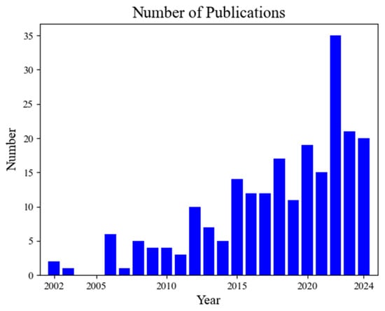
Figure 1.
Number of publications on space tracking ships on WoS.
2. Development and Technology
In the aerospace field, tracking [28,29,30], measurement [31] and control technology [32] during launch tests plays a vital role [33]. With the progress of aerospace science and technology, the ground measurement and control communication system came into being and has been continuously developed and improved [34,35]. Especially in the manned spaceflight project, it is not only necessary to realize real-time communication between the vehicle and the ground station [36,37], but also to ensure the stability of high-quality image transmission [38].
Due to the increasing range of missile weapons, traditional land-based measurement equipment was limited by geographic environmental factors and effective distance, and was unable to meet the measurement needs of the full flight test [39,40]. To this end, in the 1950s, the United States took the lead in technological innovation, land-based measurement and control equipment for adaptive transformation deployed on ship platforms. These specially adapted ships performed tracking measurements and remote control commands in predetermined sea areas, thus giving birth to the new measurement and control platform of the sea measurement ship [41,42,43].
With the rapid progress of manned spaceflight technology, higher requirements have been put forward for measurement and control communication coverage, which has greatly promoted the technological development of space tracking ships [44,45]. From a global perspective, the former Soviet Union and the United States established maritime test ranges at almost the same time, expanding the vehicle measurement and control communication network from land-based to sea-based platforms [46,47]. This strategic initiative not only enhanced measurement and control capabilities, but also significantly expanded the application areas of strategic weapons systems and space launch missions [48,49,50].
2.1. History of Development in Different Countries
- (1)
- USA
As a pioneer in the development of space tracking ship technology, the United States’ research in this field can be traced back to the mid-20th century. Its development history can be divided into four important phases, reflecting the close integration of technological evolution and mission requirements [51].
The first phase (1957–1963) involved basic ships adapted for missile trajectory tracking and satellite monitoring [52,53]. The second phase (1964–1966) introduced comprehensive platforms like the General Vandenberg and General Arnold, which handled complex tasks such as ballistic missile data acquisition and re-entry monitoring [54,55]. The third phase (1967–1971) supported the Apollo manned lunar landing program with specialized ships [56], including the Redstone for orbit tracking and the Watertown for re-entry monitoring [57,58,59]. The fourth phase (1971–present) marked modernization, with ships like the Observation Island and Range Sentinel featuring advanced phased-array radar systems for enhanced tracking precision [60,61,62]. This evolution reflects the U.S.’s strategic focus on integrating technological innovation with mission demands [63,64,65].
The USA modernized its fleet in the 1990s and 2000s to meet contemporary space mission demands. The USNS Invincible, commissioned in 2000, is equipped with a dual-band radar system for tracking ballistic missiles and space objects. Similarly, the USNS Howard O. Lorenzen, commissioned in 2012, features the Cobra King radar, a cutting-edge phased-array system supporting missile defense and space surveillance. These vessels have played critical roles in missions ranging from satellite launches to intercontinental ballistic missile (ICBM) tests, highlighting the U.S.’s continued leadership in space tracking technology.
- (2)
- USSR/Russia
The former Soviet Union initiated space tracking ship development in 1958, initially converting small and medium-sized old ships into measurement platforms [66,67]. By the 1980s, their fleet had grown to approximately 30 ships, with the Pacific measurement fleet in Vladivostok playing a central role [68,69]. Following Yuri Gagarin’s historic space flight in 1961 [70], investment surged, leading to the construction of specialized survey ships such as the Krylov and Komarov [71,72,73]. In 1971, the Soviet Union launched the Yuri Gagarin [74], the world’s largest space tracking ship at the time, marking a significant leap in their maritime measurement capabilities [75]. This expansion underscores the Soviet Union’s commitment to enhancing its space exploration infrastructure. In the 1980s, the USSR continued to promote the construction of survey ships, and built two new types of survey ships, the Marshal Nedelin and the Kapusta [76]. It is noteworthy that all the space survey ships built during the Soviet period have been inherited and continue to be used by Russia [77].
The Marshal Krylov, originally commissioned in 1987, remains operational today following extensive upgrades to its radar and communication systems. Modernized to support current space activities, it has been instrumental in missions such as the Spektr-R radio telescope launch and various Soyuz missions. These enhancements demonstrate Russia’s ongoing commitment to maintaining a robust space tracking fleet, ensuring its relevance in contemporary space exploration.
- (3)
- France
France independently developed its aerospace measurement and control technology, beginning in 1968 with the conversion of a commercial oil tanker into a maritime measurement platform [78]. By the 1990s, France achieved a major breakthrough with the Monge [79], a second-generation large-scale integrated measurement ship. Equipped with advanced systems like telemetry antennas, optoelectronic tracking, and laser impulse radar [80,81], the Monge represented a significant advancement in France’s ability to support complex space missions [82]. This development highlights France’s focus on self-reliance and innovation in aerospace technology [83,84].
- (4)
- China
China’s space tracking ship development began in the 1960s, driven by the need for maritime measurement and control to support intercontinental ballistic missile technology [85,86,87,88,89]. As missile ranges lengthened beyond land measurement and control range, relying only on land-based radio measurement made it difficult to meet accuracy requirements, and it became necessary to deploy a sea measurement platform for close-range tracking and monitoring [12]. The “718 Project”, initiated in 1967, led to the creation of the Yuanwang series [90,91]. The first generation, Yuanwang 1 and 2, were commissioned in 1979, marking China’s entry into maritime measurement and control [92,93,94,95]. Subsequent generations, including Yuanwang 3 (1994) [96], 4 (1999) [97,98], 5 and 6 (2007) [99,100,101,102,103,104], and 7 (2016), showcased progressive improvements in technology and capability. The Yuanwang 7 [105], in particular, represents the pinnacle of China’s advancements, supporting missions like Tiangong-2 and Chang’e-4 [106,107,108]. This trajectory reflects China’s growing prominence in space exploration and measurement technology. The following Table 1 shows the outer scale parameters of various stages of the “Yuanwang” series.

Table 1.
Outer Scale Parameters of Yuanwang Series.
2.2. The Structure of Space Tracking Ships
The development and fabrication of a space tracking ship is a highly complex systematic project that requires the integration of multidisciplinary knowledge and technical fields. At the early stage of design, several key elements must be considered comprehensively, which will be elaborated in this paper from the dimensions of external dimensions and internal systems [109,110,111,112].
The external dimensions mainly include the core indexes such as hull length, width, depth, and draught. These interrelated elements together determine the overall performance and functional characteristics of the ship [113,114,115,116]. The internal system consists of two major parts—the hull platform [117,118] and the measurement, control, and communication equipment [119,120,121]—of which the hull platform is the basic support system [122].
Different from commercial ocean-going freighters that pursue economic benefits and timeliness [123], space tracking ships need to meet more stringent technical requirements. As the measurement mission area is mostly located in the mid-to-high latitude sea area and the operation cycle is long, the route design needs special consideration and often faces more complicated sea conditions [124,125,126,127]. In order to ensure measurement and control accuracy, the ship must complete a series of tests such as in-dock calibration, dynamic flight calibration, accuracy verification, and multiple-system intermodulation before delivery to ensure that all equipment is in the best working condition [128,129,130].
It is worth noting that, under adverse sea conditions, the swaying and vibration of the ship may lead to an increase in the error or even failure of the measurement and control equipment [131,132]. Therefore, the design of the space tracking ship should not only ensure the safety of the ship’s hull, but also give full consideration to the stability requirements of the measurement and control equipment, so as to realize the double guarantee of navigation safety and measurement and control precision [133,134].
- (1)
- External scale
The external dimensions of a space measurement vessel significantly influence its navigation performance in marine environments. The vessel’s length critically affects its response to wave-induced motion, impacting its ability to maintain stability across diverse sea conditions [135]. This stability is essential for the effective operation of onboard precision measurement equipment. In designing the optimal main dimensions, the goal is to minimize displacement while satisfying requirements for stability, unsinkability, speed, seaworthiness, and compartment volume. Building on extensive experimental data and experience from Soviet scientists, the relationship between the vessel’s displacement and its main dimensions is described by the following formula [136]:
where represents solid ballast and solid–liquid ballast, including on-board loads to satisfy the requirements for stability, unsinkability, and speed, and depends on the coefficients of the relationship between the main scales of a modern survey vessel, as shown in Figure 2, and can be approximated as follows:
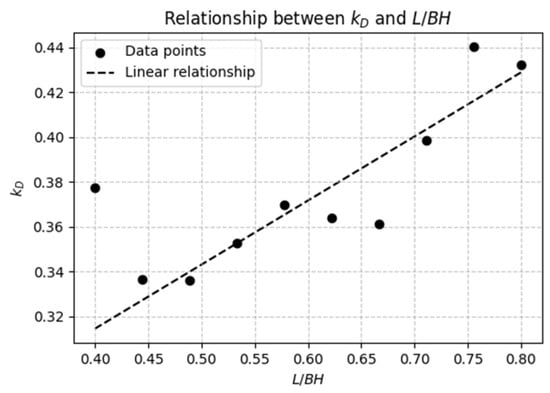
Figure 2.
Relationship between kD and L/BH.
In practice, the parameter P6 should be made sufficiently small, and we assume the ideal case, which is solved by the union of Equations (1) and (2):
From Equation (3), it can be seen that in order to reduce the displacement, the number of cubic meters and the length of the ship should be reduced, but the ship’s length should be considered at the same time. The width of the ship is closely related to the guarantee of electromagnetic compatibility of the required communication equipment and the sufficient viewing angle of the antenna.
The ship’s width is closely related to the ship’s lateral stability, and sufficient ship width can effectively resist the influence of transverse winds, waves, and other external factors that bring about the transverse rocking, to ensure that the measurement equipment operates accurately in the horizontal axis, and to avoid measurement error due to the excessive tilting of the ship’s hull [137,138,139]. The depth of the ship not only provides the necessary vertical space for the reasonable layout of the ship’s internal compartments to meet the needs of the various types of equipment installed and the crew’s living quarters, but also affects the ship’s stability and resistance to sinking to a large extent, which is an important factor to ensure the safe operation of the ship in the complex marine environment [140,141].
The selection of the depth of the vessel needs to ensure the capacity of the vessel as well as its buoyancy reserve [142]. The minimum permissible depth of the main deck can be determined according to the following equation:
where is the minimum allowable total accommodation ratio; is the relative accommodation of the superstructure, 0.75 ± 0.25 under this condition, And represents the vertical prismatic coefficient.
The design of the draught depth, on the other hand, needs to take into full consideration the different navigation areas that the space tracking ship may face, not only to ensure that it can safely pass through shallow coastal waterways and harbors to carry out supply and other operations, but also to ensure sufficient navigation stability and hydrodynamic performance when carrying out the mission in distant waters, and the draught is also closely related to the normal work of some measurement equipment, such as acoustic measurement equipment, which has a requirement for the appropriate depth of the submerged components, and so forth [143,144,145,146,147]. The draught depth design can be roughly modeled by the following formula:
where is the draught depth (unit: m); is the displacement of the ship (unit: tons), including the weight of the hull, equipment load, fuel, supply material, and mission load; is water density (unit: kg/m3), 1025 kg/m3 in seawater; is the acceleration due to gravity (unit: m/s2), about 9.8 m/s2; is the waterline surface area (unit: m2), which is determined by the length and width of the hull. For complex shaped hulls, the waterline surface area needs to be calculated by integrating the waterline profile of the hull section:
where is the distribution function of the hull width at the waterline height (in m); are the fore and aft boundary points of the hull at the waterline (in m); and is the squareness coefficient, which indicates the ratio of the hull shape to the filling of an ideal rectangular volume and usually ranges from 0.6 to 0.85.
The core function of a space tracking ship is to carry and operate various kinds of high-precision space measurement equipment, which is the key to realizing the objectives of space measurement missions. Whether the outer scale is reasonable or not is directly related to whether the measurement equipment can be properly arranged and efficiently operated on board [148]. For example, large radar antennae [149] and optical measurement equipment [150] require sufficient ship length to realize a reasonable layout along the ship’s hull to avoid mutual interference and meet their respective working requirements; at the same time, the large transverse dimensions of some equipment require the corresponding width of the ship’s hull to accommodate their rotating mechanisms and other components, and to leave enough space for the operators to work.
- (2)
- Internal scale
The ship’s primary engine, constituting the core power system on a smaller scale, is principally responsible for the provision of propulsion [151,152]. The power plant can be categorized into three main forms according to the type of energy used: steam power, gas power, and nuclear power [153,154,155,156,157]. The operation of these thermal engines is predicated on the combustion of fuel, a process that converts chemical energy into thermal energy, and subsequently, mechanical energy, thereby driving the ship [158,159]. With respect to the utilization of fuel, the primary distinction is between direct and indirect utilization. The propulsion and power systems of space tracking ships are engineered to meet the unique demands of long-duration missions in remote, high-latitude sea areas. These systems ensure stability, minimize vibration to protect sensitive measurement equipment, and support the precision required for tracking fast-moving spacecraft.
Direct utilization signifies the immediate generation of propulsion subsequent to fuel combustion, whilst indirect utilization entails the transfer of energy through an intermediate medium. This energy conversion mechanism is pivotal in terms of enabling the efficient propulsion of the ship’s power systems [160,161].
- (1)
- Steam engine
A steam engine is an indirect heating type of engine, which consists of a boiler, a turbine, a condensing system, etc. The principle is shown in the figure below (Figure 3).
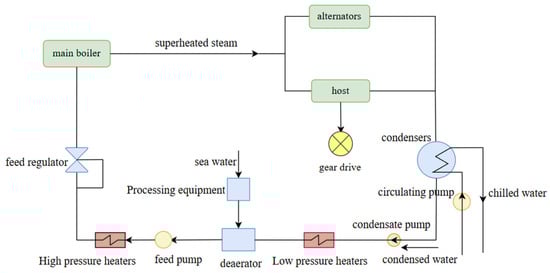
Figure 3.
Steam turbine flow chart.
The operational process of the steam turbine can be summarized as follows: Water is firstly heated at constant pressure in the boiler and gradually converted into saturated steam. Thereafter, the saturated steam is introduced into the superheater, where it undergoes a transition into superheated steam by means of constant pressure heating. The superheated steam then enters the steam turbine (main engine) through the steam pipeline, and undergoes adiabatic expansion within the turbine to output power externally and drive the steam turbine to run at high speed. The low-temperature, low-pressure steam is then discharged into the condenser, where it undergoes exothermic recondensation into water at constant pressure. The condensate is then transported to the deaerator by the condensate pump, where it undergoes deoxygenation before being re-injected into the boiler through the feed pump and high-pressure heater, thus completing the steam cycle of the steam power plant. The high-speed rotor of the steam turbine drives the propeller to rotate, thereby exerting a force on the water to propel the ship forward [162,163,164,165,166,167,168].
The steam turbine is distinguished by its high power, adaptability to fuel, smooth operation, low wear and tear, low vibration, and low noise. However, the disadvantages of the steam turbine are also more obvious, such as lower efficiency, larger size, and greater weight. While steam turbines were historically employed in some space tracking ships for their high power output, their design in these vessels prioritizes vibration reduction to avoid interference with onboard measurement systems. For example, advanced damping mechanisms are integrated to ensure that ship motion does not compromise telemetry accuracy during critical mission phases.
A more abbreviated steam turbine operation schematic is shown in Figure 4.
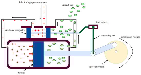
Figure 4.
Abbreviated steam turbine schematic.
- (2)
- Internal combustion engine (ICE)
ICEs, as actively heated power units, are mainly classified into two main categories, petrol and diesel engines, depending on the type of fuel employed. This paper focuses on the relevant characteristics of marine diesel ICEs.
A diesel engine takes diesel as fuel, converts chemical energy into heat energy through the combustion process, heats the combustion products to generate high-temperature and high-pressure gas, and this expands in the cylinder to do work. A diesel engine usually consists of several key mechanisms and systems, including the crank linkage mechanism, the gas distribution mechanism, the transmission mechanism, the fuel supply system, the lubrication system, the cooling system, and the starting system.
In the working process of diesel engines, the fuel is injected into the cylinder before filling the air to provide the necessary conditions for combustion. The particularity of diesel combustion is that it needs to reach a high enough temperature to self-ignite, so the piston will move upwards to compress the air, so that it reaches the high temperature and high pressure required for fuel self-ignition.
The combustion of the fuel releases a large amount of heat energy, resulting in a sharp increase in gas pressure and temperature. Subsequently, the gas expands in the cylinder to push the piston to do work, and the gas that completes the work is finally discharged from the cylinder. A diesel engine work cycle includes the five stages of intake, compression, combustion, expansion, and exhaust, and these stages are repeated. If the entire cycle of work in a four-piston stroke is completed, this is called a four-stroke diesel engine; similarly, there are also two-stroke diesel engines. For example, the Yuanwang 5 and Yuanwang 6 both use four-stroke diesel engines as their power source. Diesel engines, such as those in the Yuanwang series, are selected for space tracking ships due to their reliability and fuel efficiency during extended missions. Their design incorporates low-vibration technology to minimize disturbances to sensitive equipment, ensuring precise antenna alignment and uninterrupted data transmission.
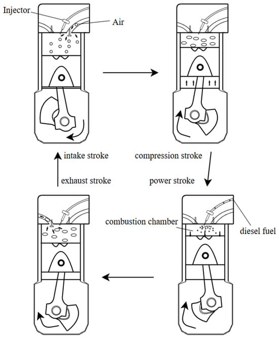
Figure 5.
The schematic diagram of the operation of a 4-stroke ICE.
- (3)
- Power system
The power system of a space tracking ship is of paramount importance for its ocean missions, and thus has irreplaceable functions. The power system consists of several subsystems, including the main power station, emergency power supply, a berthing power supply device, a shore power interface, and a medium-frequency power supply. The main power station consists of five high-power generator sets, two of which are used for measurement equipment, two of which are responsible for the propulsion system, and another standby unit. The emergency power supply system utilizes small diesel generator sets to ensure uninterrupted power in the event of a power failure. The mooring power supply system is equipped with two medium-power diesel generator sets, which are primarily employed during the ship’s anchoring period. The shore power interface facilitates connection to an external power supply during docking operations in harbors, while the medium-frequency power supply provides dedicated power for specific equipment.
The design of the power system must consider the following technical elements to ensure reliability: the implementation of multiple redundant architectures to maintain the power supply in the event of a single point of failure, and to enhance resilience to seismic and severe sea conditions. It is designed to deliver stable, uninterrupted energy to critical systems such as radar arrays and telemetry antennas. Redundant generators and advanced power management ensure that, even in rough seas, the ship maintains the precision required for real-time spacecraft tracking during peak operational periods, such as satellite passes or re-entry monitoring. With regard to energy efficiency optimization, priority should be given to the deployment of high-efficiency and low-emission power generation equipment, with the integration of renewable energy sources being a key consideration. The thermal management system should be designed to ensure the heat dissipation efficiency of the equipment during long-term operation. To achieve intelligent management, the provision of real-time monitoring and power regulation systems is essential for optimal energy allocation. In terms of equipment maintenance, a modular design should be adopted to allow for quick overhauls, and the system should operate in strict compliance with international maritime environmental regulations [175,176,177].
2.3. Space Tracking Ship Communications Capability
Space tracking ships are essential for monitoring and supporting space missions, providing critical communication links between spacecraft and ground control. These vessels operate in remote ocean areas, where terrestrial communication networks are unavailable, necessitating robust and reliable communication systems. The maritime environment presents unique challenges, including signal attenuation due to distance, interference from natural and man-made sources, and the dynamic motion of the ship itself. To overcome these obstacles, space tracking ships employ advanced communication technologies designed to ensure continuous, high-quality data transmission. This section explores the key technologies that enable these capabilities, focusing on their practical applications and significance in maintaining effective communication during space missions.
2.3.1. High-Frequency Communication Technology
High-frequency (HF) communication, operating in the 3–30 MHz range, serves as a foundational technology for space tracking ships, enabling reliable, long-distance data exchange across vast oceanic expanses. Unlike shorter-range systems such as VHF or UHF, HF signals leverage ionospheric reflection to bounce off the upper atmosphere, enabling communication beyond the horizon. This unique capability makes HF indispensable for vessels tasked with monitoring spacecraft launches, orbits, and re-entries from remote maritime locations, ensuring seamless connectivity with mission control and orbiting assets.
China’s Yuanwang fleet has relied on HF systems to relay telemetry data from spacecraft like the Chang’e lunar probes back to shore-based stations, even when positioned thousands of kilometers from land. During the Shenzhou manned missions, these ships used HF to transmit real-time positional and health data from capsules in orbit, bridging the gap between space and ground operations. This long-range resilience is particularly valuable in scenarios where satellite links are unavailable or disrupted, offering a robust backup for maintaining mission continuity.
Despite its strengths, HF communication faces significant challenges due to its dependence on the ionosphere. Solar flares, geomagnetic storms, and diurnal shifts can distort or weaken signals, sometimes rendering communication unreliable. For example, during periods of intense solar activity, space tracking ships may experience signal fading or complete blackouts, jeopardizing data transmission. To counter these issues, modern vessels employ adaptive techniques such as real-time frequency hopping—where the system shifts to an optimal frequency based on current ionospheric conditions—and digital signal processing (DSP), which filters noise and enhances signal clarity. The U.S. tracking ship the Howard O. Lorenzen exemplifies this approach, using advanced DSP to maintain stable HF links during high-stakes operations.
The evolution of HF communication reflects broader research trends identified in Section 3, particularly the integration of cutting-edge technologies. Artificial intelligence (AI) is increasingly applied to predict ionospheric behavior, using historical and real-time data to anticipate disruptions and adjust communication parameters proactively. This predictive capability reduces downtime and boosts reliability, a critical advantage for ships tracking fast-moving spacecraft. Additionally, software-defined radio (SDR) systems are transforming HF setups by replacing rigid hardware with flexible, programmable platforms. SDR enables operators to reconfigure communication protocols on the fly, adapting to diverse mission needs without physical upgrades.
2.3.2. Anti-Interference
Anti-interference technologies play a pivotal role in ensuring the reliability of space tracking systems, particularly for ships tasked with monitoring spacecraft in challenging maritime environments. These systems must contend with a barrage of electromagnetic interference, from natural sources like solar activity to artificial disruptions such as radar signals from nearby vessels. Robust anti-interference measures are vital to preserve the accuracy of telemetry data and maintain seamless communication links during mission-critical operations [178,179,180].
In practice, anti-interference technologies enable space tracking ships to perform under demanding conditions. For example, during the Apollo missions, tracking vessels like the USNS Vanguard relied on anti-jamming capabilities to maintain contact with spacecraft despite interference from atmospheric disturbances. These technologies ensure that signals carrying positional data or commands remain intact, supporting precise orbital tracking and re-entry operations.
The primary challenges stem from unpredictable interference sources that degrade signal quality. Solar flares can elevate noise levels, while overlapping frequencies from other maritime systems may jam communication channels. To address these issues, several strategies are employed:
Frequency Agility: Systems switch between frequencies to avoid interference zones.
Noise Filtering: Real-time digital processing isolates the desired signal from background noise.
Directional Control: Antennas adjust their focus to prioritize mission signals over stray emissions.
A key metric in these efforts is the signal-to-noise ratio (), simplified as:
where represents the power of the intended signal and denotes interference power. A higher SNR indicates clearer communication, guiding the design of effective anti-interference systems.
By integrating practical mitigation strategies and maintaining a focus on signal clarity—as exemplified by metrics like —these systems ensure mission success.
2.3.3. Antenna Servo System
Antenna servo systems are essential for precision tracking in space monitoring, enabling antennas to maintain accurate alignment with fast-moving targets such as satellites or spacecraft. These systems integrate motors, sensors, and control algorithms to adjust the antenna’s orientation in real time, compensating for both target motion and platform instability. In maritime space tracking, such as on ships navigating turbulent seas, servo systems must overcome additional challenges posed by waves and wind, making their reliability and responsiveness critical to mission success [181,182,183].
One notable application is in China’s Yuanwang space tracking ships, which supported the Chang’e lunar missions. These vessels relied on advanced servo systems to keep antennas locked onto the lunar probe, adjusting for the ship’s pitch and roll to ensure continuous data transmission.
Antenna servo systems face significant challenges, particularly in dynamic environments. Key issues include environmental disturbances (e.g., ship motion) and the need for rapid, precise corrections to track high-speed targets. Several strategies address these:
Feedback Loops: Sensors monitor the antenna’s position relative to the target, calculating the tracking error,
where is the desired angle and is the current angle. This error drives motor adjustments to minimize deviation.
Predictive Algorithms: By analyzing past target trajectories, these systems anticipate movements, reducing response lag.
Stabilization Platforms: Gyro-stabilized mounts counteract external motion, providing a stable base for the antenna.
Together, these approaches ensure consistent target lock, even under adverse conditions.
2.3.4. Frequency Shift Compensation Techniques
Frequency shift compensation is essential in space tracking systems to counteract the Doppler effect [184], which alters the frequency of signals due to the relative motion between a transmitter (e.g., a satellite) and a receiver (e.g., a tracking ship). Without compensation, this frequency shift can disrupt communication, leading to data loss or misinterpretation. In space tracking, where targets move at high speeds, accurate compensation ensures that signals remain stable and interpretable, maintaining the integrity of mission-critical data [185,186].
A practical example of frequency shift compensation is during a low Earth orbit (LEO) satellite pass over a tracking ship. As the satellite approaches, its signal frequency increases, and as it recedes, the frequency decreases. For instance, during the tracking of the International Space Station (ISS), ships like the USNS Howard O. Lorenzen use real-time compensation to adjust for these shifts, ensuring continuous, accurate telemetry. This capability is vital for tasks like orbital adjustments or emergency communications, where precision is paramount.
The primary challenge in frequency shift compensation lies in predicting and adjusting for the dynamic nature of the Doppler effect, especially in environments with variable target speeds and trajectories. Several strategies are employed to address this:
Real-Time Calculation: Systems compute the frequency shift using the basic Doppler formula,
where is the relative velocity, is the speed of light, and is the original frequency. This calculation guides immediate adjustments.
Predictive Modeling: By analyzing the target’s trajectory, systems can anticipate frequency changes and pre-adjust, reducing lag.
Adaptive Filtering: Digital filters refine the signal, correcting for unexpected shifts caused by atmospheric conditions or equipment limitations.
By integrating real-time calculations, predictive adjustments, and adaptive filtering, these systems ensure signal integrity in dynamic scenarios.
3. Bibliometric Analysis
This paper employs bibliometric techniques to examine the extant literature on space tracking ships. The literature on space tracking ships was analyzed using a range of indicators, including journals, subject categories, countries, and institutions.
The literature was sourced from the Web of Science (WOS), a comprehensive scientific citation index database comprising a vast array of significant publications spanning multiple disciplines over the past century.
The database comprises a significant corpus of literature from a range of disciplines, spanning the past century. The research encompasses a range of significant literature from diverse academic disciplines. It is a reliable source of literature for scholars, as it encompasses the most influential journals across a range of disciplines. This platform is widely regarded as a highly authoritative source within the academic community.
Figure 6 illustrates the retrieval process of space tracking ship. An advanced search was conducted on the Web of Science website using the following search formula: TS = ((“tracking” OR “support” OR “telemetry”) AND (“ship” OR “vessel”) AND (“space”)) NOT TS = (“vascular” OR “blood vessel”). The selected databases are Web of Science core databases, with time slices covering all available data, and the language set to English. To ensure the integrity of our data sample, we relied on the WoS’s rigorous standards for peer-reviewed content, employed a targeted search strategy to capture pertinent studies while excluding unrelated topics, and conducted manual verification to guarantee accuracy and completeness. These steps ensure that our bibliometric analysis rests on a reliable and trustworthy dataset, enhancing the validity of our findings. An initial search retrieved 481 relevant publications, which were then screened manually using CiteSpace for manual screening and duplicate removal. Ultimately, 226 eligible sources were identified.
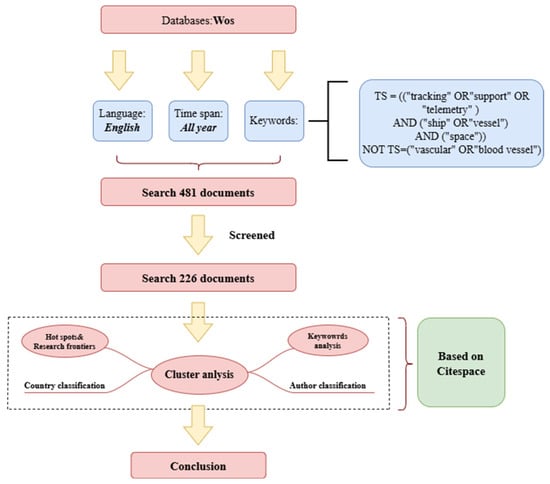
Figure 6.
Schematic diagram of the search process.
3.1. Country Analysis
A country-by-country analysis was carried out on a selection of 226 publications on space tracking ships, published in 52 countries or regions. We have mapped the countries that have participated in the space tracking ship-themed papers on the website mapchart. The output image is shown in Figure 7.
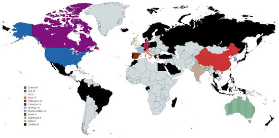
Figure 7.
Distribution of countries and regions with published papers on space tracking ships.
As illustrated in Figure 7, the majority of countries that have published on space tracking ships are located in coastal areas. Of the 52 samples analyzed in this study, only two are located inland—Switzerland and Luxembourg. These two countries represent only 3.8% of the total sample, which is consistent with our general knowledge.
Analyzing the distribution of countries alone is not enough, we use CiteSpace to perform country clustering analyses.
In citespace, the parameters are set as follows:
Node type—select country, time slicing from 2002 to 2024, 1 year per slice, node type—select country. Selection criteria—select g-index where k = 25; in pruning, tick pathfinder and prune the merged network. The output image is shown in Figure 7.
In the citespace output of the country clustering in Figure 8, the nodes represent countries, where the larger nodes represent a greater number of publications in this country; in the statistical process, the largest number of publications is from China with 81, followed by the USA with 50, followed by the UK and Italy with 21 and 17, respectively.
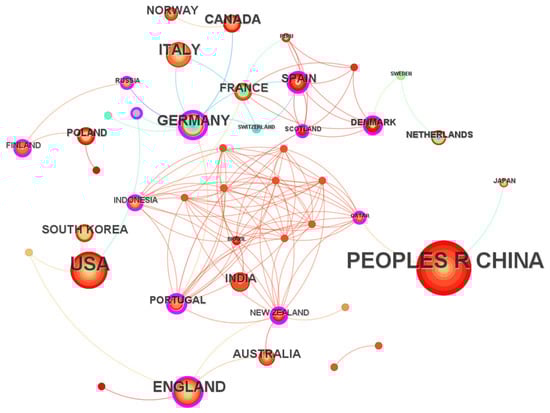
Figure 8.
Relationship map of countries where the literature is published based on CiteSpace analysis.
The color of the node represents the year of publication, e.g., the closer the node color is to red, the closer the publication is to the present; in the graph China, the USA, Australia, and India are all countries that have been focusing on this area in recent years. Indonesia, Germany, Portugal, and Spain are countries that focused on this area in the early years but have no longer done so in recent years.
The lines between the nodes represent cooperation between countries, with China and the United States, the top two in terms of publications, having fewer cooperation relationships. China only cooperates with Japan and Qatar, while the United States only cooperates with South Korea, Indonesia, Luxembourg, and Gabon, and the quantity of inter-country cooperation is very small. The complex web of relationships at the center of the picture is also just one paper containing authors from multiple countries. There is less cooperation between countries.
3.2. Institutional Analysis
There are a total of 282 institutional samples in the cluster analysis of institutions, the parameter settings are basically the same as those of the national analysis, the node types are replaced with institutions, and the output image is shown in Figure 9.
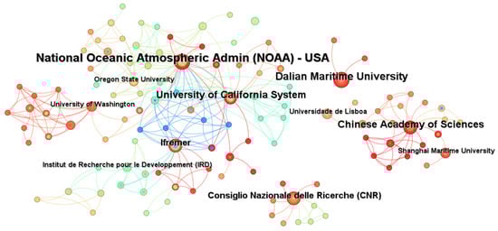
Figure 9.
Relationship map of institutions where the literature is published based on CiteSpace analysis.
In this institutional cluster analysis, the National Oceanic and Atmospheric Administration (NOAA) and Dalian Maritime University had the highest number of publications, with 13 and 10 documents, respectively. They were closely followed by the University of California System, the Chinese Academy of Sciences, and Ifremer, which had 9, 8, and 6 publications, respectively.
Similarly to the country clustering analysis, the deeper red of the node indicates a greater frequency of recent publications, suggesting that the institution is prioritizing the field. Dalian Maritime University and the Chinese Academy of Sciences have been particularly active in this field only in recent years, as evidenced by the monochromatic color of their nodes. Conversely, Ifremer, in collaboration with the NOAA and other institutions, has a more diverse range of colors in their nodes, indicating that they commenced their research activities at an earlier stage and have been engaged in studies related to space tracking ships.
The nodes in Figure 9 are divided into sections centered on the NOAA, Dalian Maritime University, the Chinese Academy of Sciences, and CNR. It should be noted that there are no connecting lines between these sections, which indicates that they are not connected to each other and are independent of each other. It is evident that the section centered on the NOAA has established collaborative relationships with American institutions, whereas the analogous structure centered on the Chinese Academy of Sciences has formed partnerships primarily with Chinese companies. This phenomenon is similarly observable in the CNR-centered section. This is another indication of the low level of international cooperation on space tracking ships.
3.3. Keywords Analysis
In this section, we employ CiteSpace to analyze the keywords associated with space tracking ships, aiming to identify shifts in research focus over time. It should be noted that due to the excessive number of keywords, we adjusted the g-index to k = 16 to limit the number of nodes to 300, as required by the software. Figure 10 presents the output image from this analysis.
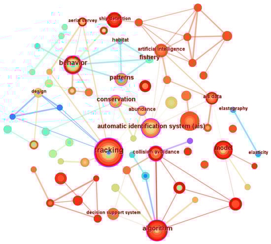
Figure 10.
Relationship map of keywords where the literature is published based on CiteSpace analysis.
As in the previous cluster analysis, the size of the nodes corresponds to the frequency of keyword occurrences, with nodes closer to red indicating more recent research hotspots. In this keyword analysis, the term “tracking” appeared most frequently, with 27 occurrences, followed by “algorithm” and “AIS” with 14 and 12 occurrences, respectively. The keywords are closely interconnected, reflecting the interdisciplinary nature of the field and the diverse directions for future research.
Merely observing the clustering diagram does not allow for an accurate understanding of the dynamic changes in research hotspots related to space tracking ships. Therefore, we utilized the keyword mutation function in CiteSpace, selected ‘burstness’ in the control panel, and set the γ-value to 0.3 to generate the keyword mutation table presented in Figure 11.
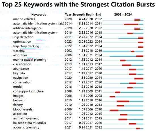
Figure 11.
Keyword mutation table using CiteSpace.
As shown in Figure 11, the three keywords with the highest mutation intensity are “marine vehicle”, “AIS”, and “AI”. Lloyd’s List Intelligence has announced the launch of a new ship tracking system called AIS+, which combines Automatic Identification System (AIS) data with artificial intelligence to provide insights into ship movements, movement history, and predicted movements. This fusion of technologies makes navigation safer and smarter, and is equally applicable to the space tracking ship sector.
The Automatic Identification System (AIS) is a vital maritime safety tool that provides real-time data on vessel identity, position, course, speed, and other critical information to ships, shore stations, and aircraft. Using VHF radio frequencies, AIS enables collision avoidance, traffic management, and search and rescue operations. While effective in busy coastal waters, its reliance on nearby shore-based stations limits its range, leaving gaps in coverage in remote areas like the open ocean or near Antarctica.
These limitations are significant in regions with sparse maritime infrastructure. For example, satellite-based AIS (S-AIS) extends coverage beyond terrestrial stations, but its performance can falter in extreme environments due to signal delays or interference. Figure 12, a heat map of ship routes between Asia and the Americas in 2023 from Marine Traffic, illustrates dense traffic in those corridors, yet highlights the rarity of routes near Antarctica. This scarcity, combined with the harsh environment and lack of base stations, increases navigational risks for vessels in such areas.
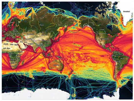
Figure 12.
The heat map of ship routes between Asia and the Americas in 2023 from Marine Traffic.
Space tracking ships, originally deployed to monitor satellite trajectories and relay data to ground stations, offer a solution. Equipped with advanced communication systems, including integrated base stations for satellite signals, these ships frequently operate in remote oceanic regions, such as near Antarctica. By leveraging their capabilities, space tracking ships can act as mobile AIS relay points. They can receive AIS signals from nearby vessels and transmit them to satellites or other networks, enhancing situational awareness where traditional and satellite AIS coverage is insufficient.
This dual role is practical because space tracking ships are already deployed for space missions. Rather than requiring dedicated voyages for maritime safety, they can opportunistically relay AIS signals during their existing operations. For instance, a ship tracking a satellite near Antarctica could simultaneously strengthen the AIS network, providing critical data to vessels in the vicinity.
However, challenges exist. Operating in remote and hostile environments demands robust technology to withstand extreme weather, alongside logistical and maintenance complexities. Financially, the high costs of space tracking ships—designed primarily for space missions—make dedicated AIS deployments impractical. Yet, integrating AIS relay into their primary missions minimizes additional expenses, maximizing their utility without significant investment.
In summary, space tracking ships can enhance maritime safety in remote areas by relaying AIS signals where traditional coverage is limited. This approach leverages their advanced communication systems and existing presence in regions like near Antarctica, offering a cost-effective way to bridge communication gaps and improve navigational safety.
4. Conclusions
This paper has provided a comprehensive overview of the current status and historical development of space tracking ships, with a particular focus on their measurement and control technology. The analysis has highlighted the critical role that space tracking ships play in modern space exploration, particularly in the context of missile and spacecraft tracking, telemetry, and communication.
The historical development section has shown that space tracking ships have evolved significantly over the decades, with major advancements in technology and design. The United States, the former Soviet Union, France, and China have all made substantial contributions to this field, each with their unique approaches and technological innovations. The development of these ships has been driven by the need to support increasingly complex space missions, including manned lunar landings, interplanetary explorations, and satellite launches.
The structural analysis of space tracking ships has emphasized the importance of both external and internal design considerations. The external dimensions, such as hull length, width, and draught, are crucial for ensuring the stability and navigational capabilities of these vessels. The internal systems, including power generation, communication, and measurement equipment, are equally vital for the successful execution of their missions. The detailed discussion of power systems, communication capabilities, and antenna servo systems underscores the complexity and sophistication of these platforms.
The bibliometric analysis has provided valuable insights into the research trends and collaborative efforts in the field of space tracking ships. The analysis revealed that while China and the United States are the leading countries in terms of publication output, there is a noticeable lack of international collaboration in this area. This suggests potential opportunities for future research and development through enhanced global partnerships.
The discussion on AIS technology and its application in ship tracking has highlighted the challenges and opportunities in remote maritime environments, such as Antarctica. The integration of AIS with satellite systems and AI presents promising avenues for improving maritime safety and surveillance in these regions.
4.1. The Limitations of the Study
This study provides a broad perspective on the development and technology of space tracking ships, but some limitations should be recognized. Firstly, the bibliometric analysis was limited to English-language publications indexed in the Web of Science, which may not fully reflect the extent of research in non-English-speaking countries, particularly in regions such as Russia and China, which have made significant contributions to space tracking technology. Secondly, the analysis focuses primarily on the output and citation patterns of the publications without delving into the detailed technical aspects of the measurement and control systems on these vessels. This limits the depth of understanding of the technological advances and challenges faced in this field. The description of some of the communication technologies is limited to the derivation of formulaic theories and there is no in-depth analysis of the feasibility of certain technologies. Because space tracking ships are part of the military domain, their secrecy is high, and some of the ship’s outer scale parameters can only be obtained from data that is already publicly available on the web, with no guarantee of their authenticity.
In addition, the study relies on bibliometric tools such as CiteSpace for clustering and visualization, which may create bias in interpreting research trends. The algorithms used in such tools are based on specific methodologies, and different tools or parameters may produce different results. Therefore, the results of the study should be interpreted with caution and validated by other analytical methods.
4.2. Directions for Future Research
In order to address the identified limitations and further advance the field of space tracking ship research, we propose several avenues for future research:
In-depth technical analyses: Future research should focus on more detailed technical analyses of the measurement and control systems of space tracking ships. This may include case studies of specific vessels (e.g., the Yuanwang series) to explore the integration of advanced technologies such as artificial intelligence and machine learning in navigation, tracking, and communication systems.
International Collaboration: The low level of international collaboration observed in the bibliometric analysis suggests the need for more cross-border research activities. Collaborative projects can enhance the exchange of knowledge and expertise that can lead to breakthroughs in space tracking technology. For example, joint ventures between Chinese, United States, and European institutions could foster innovation in areas such as autonomous navigation, real-time data processing, and advanced communication systems. But because of the nature of space tracking ships and their military secrecy, cooperation between some countries may be difficult to develop, which remains a major barrier to progress in this area.
Environmental Impact Assessment: As space tracking ships are increasingly used for a variety of missions, there is a growing need to assess their environmental impact, especially in sensitive areas such as Antarctica. Future research could explore the ecological impact of these ships, including possible marine pollution and disturbance of marine life. This will contribute to the development of sustainable practices for space exploration.
Convergence of Artificial Intelligence and Machine Learning: Rapid advances in artificial intelligence and machine learning offer significant opportunities to improve the capabilities of space tracking ships. Future research could investigate the potential of these technologies to improve target tracking accuracy, optimize communication systems and increase the overall efficiency of space missions.
Policy and Regulatory Framework: Because space tracking ships play a critical role in national security and space exploration, there is a need for a comprehensive policy and regulatory framework to govern their operations. Future research could explore the development of international standards for the design, deployment, and operation of these vessels to ensure compliance with environmental, safety, and security regulations.
In summary, space tracking ships are indispensable assets in the global space exploration endeavor, and their continued development is crucial for advancing space technology. Future research should focus on addressing the technical challenges associated with operating in extreme environments, enhancing the interoperability of communication systems, and exploring the potential of emerging technologies, such as AI, to further improve the capabilities of these vessels. As space missions become more ambitious and complex, the role of space tracking ships will only grow in importance, necessitating sustained investment in research, development, and international collaboration.
Author Contributions
Conceptualization, H.J. and D.Z.; methodology, D.Z. and Y.M.; software, H.J.; validation, D.Z., S.Z. and Y.T.; formal analysis, D.Z.; investigation, S.Z.; resources, H.J. and D.Z.; data curation, Y.T.; writing—original draft preparation, Y.M. and H.J.; writing—review and editing, D.Z.; visualization, Y.T.; supervision, H.J. and D.Z.; project administration, H.J.; funding acquisition, H.J. All authors have read and agreed to the published version of the manuscript.
Funding
This research was funded by the National Natural Science Foundation of China, grant number 62272109, and the Zhanjiang Marine Youth Talent Project—Comparative Study and Optimization of Horizontal Lifting of Subsea Pipeline, grant number 2021E5011.
Data Availability Statement
All data generated and analyzed during this study are included in this published article. The datasets used and analyzed during the current study are available from the corresponding author on reasonable request.
Conflicts of Interest
The authors declare no conflicts of interest.
References
- Wu, B.; Xu, Z. Research on integrated space-air-ground TT&C and communication network based on space tracking ship. In Proceedings of the 2017 16th International Conference on Optical Communications and Networks (ICOCN), Wuzhen, China, 7–10 August 2017; IEEE: Piscataway, NJ, USA, 2017. [Google Scholar]
- Soltani Mohsen, N.; Izadi-Zamanabadi, R.; Wisniewski, R. Reliable control of ship-mounted satellite tracking antenna. IEEE Trans. Control. Syst. Technol. 2010, 19, 221–228. [Google Scholar] [CrossRef]
- Zalewski, P.; Bąk, A.; Bergmann, M. Evolution of maritime GNSS and RNSS performance standards. Remote Sens. 2022, 14, 5291. [Google Scholar] [CrossRef]
- Mao, H.; Sinn, T.; Vasile, M.; Tibert, G. Post-launch analysis of the deployment dynamics of a space web sounding rocket experiment. Acta Astronaut. 2016, 127, 345–358. [Google Scholar] [CrossRef]
- Caruzzo, A.; Belderrain, M.C.N.; Fisch, G.; Manso, D.F. The mapping of aerospace meteorology in the Brazilian Space Program: Challenges and opportunities for rocket launch. J. Aerosp. Technol. Manag. 2015, 7, 7–18. [Google Scholar] [CrossRef][Green Version]
- Wang, J. The current status and future aspects in formal ship safety assessment. Saf. Sci. 2001, 38, 19–30. [Google Scholar] [CrossRef]
- Li, X.; Zhang, Z.; Li, H. GPS data processing method for at-sea accuracy qualification of external measurement equipment on aerospace measurement ships. Telemetry 2007, S1, 228–233. (In Chinese) [Google Scholar]
- Gu, J.; Chu, W.; Zhai, Y.; Wang, G. Discussion on quality supervision of the development and modification of measurement and control communication equipment for aerospace measurement ships. Qual. Reliab. 2009, 6, 5–9. (In Chinese) [Google Scholar]
- Xu, H. Predictive Control and Simulation of Path Tracking of Aerospace Survey Vessel. Master’s Thesis, Shanghai Jiao Tong University, Shanghai, China, 2013. (In Chinese). [Google Scholar]
- Guo, Z.; Li, J. Development of China’s first-generation aerospace ocean-going survey ship under the perspective of sea-land-air integration. Nat. Dialectics Lett. 2024, 46, 62–68. (In Chinese) [Google Scholar] [CrossRef]
- Delaney, W. From vision to reality 50+ years of phased array development. In Proceedings of the 2016 IEEE International Symposium on Phased Array Systems and Technology (PAST), Waltham, MA, USA, 18–21 October 2016; IEEE: Piscataway, NJ, USA, 2016. [Google Scholar]
- Sharpe, M.R.; Lowther, J.M. Progress in Rocket, Missile, and Space Carrier Vehicle Testing, Launching, and Tracking Technology. Adv. Space Sci. Technol. 1965, 7, 1–145. [Google Scholar]
- Esper, J.; Flatley, T.P.; Bull, J.B.; Buckley, S.J. Small Rocket/Spacecraft Technology (SMART) Platform. In Proceedings of the Annual AIAA/USU Conference on Small Satellites, Logan, UT, USA, 8–11 August 2011. [Google Scholar]
- Launius, R.D.; Conway, E.M.; Johnston, A.K.; Wang, Z.C.; Hersch, M.H.; Paikowsky, D.; Whalen, D.J.; Toldi, E.; Dougherty, K.; Hays, P.L.; et al. Spaceflight: The development of science, surveillance, and commerce in space. Proc. IEEE 2012, 100, 1785–1818. [Google Scholar] [CrossRef]
- Bravo, J.; Villarreal, V.; Hervás, R.; Urzaiz, G. Using a communication model to collect measurement data through mobile devices. Sensors 2012, 12, 9253–9272. [Google Scholar] [CrossRef] [PubMed]
- Dudojc, B.; Mindykowski, J. New approach to analysis of selected measurement and monitoring systems solutions in ship technology. Sensors 2019, 19, 1775. [Google Scholar] [CrossRef] [PubMed]
- Abotaleb, M.; Mindykowski, J.; Dudojc, B.; Masnicki, R. Case-Study-Based Overview of Methods and Technical Solutions of Analog and Digital Transmission in Measurement and Control Ship Systems. Sensors 2022, 22, 6931. [Google Scholar] [CrossRef] [PubMed]
- Psiaki, M.L. Autonomous orbit determination for two spacecraft from relative position measurements. J. Guid. Control. Dyn. 1999, 22, 305–312. [Google Scholar]
- Baranov, A.A. Change of spacecraft position in a satellite system. Cosm. Res. 2008, 46, 215–218. [Google Scholar] [CrossRef]
- Oshman, Y.; Dellus, F. Spacecraft angular velocity estimation using sequential observations of a single directional vector. J. Spacecr. Rocket. 2003, 40, 237–247. [Google Scholar]
- Guibaud, A.; Legros, G.; Consalvi, J.-L.; Torero, J. Fire safety in spacecraft: Past incidents and Deep Space challenges. Acta Astronaut. 2022, 195, 344–354. [Google Scholar] [CrossRef]
- McKenzie, I.; Ibrahim, S.; Haddad, E.; Abad, S.; Hurni, A.; Cheng, L.K. Fiber optic sensing in spacecraft engineering: An historical perspective from the European space agency. Front. Phys. 2021, 9, 719441. [Google Scholar]
- Xu, J.; Li, J.; Xu, S. Data fusion for target tracking in wireless sensor networks using quantized innovations and Kalman filtering. Sci. China Inf. Sci. 2012, 55, 530–544. [Google Scholar] [CrossRef]
- Klepsch, J.; Klüppelberg, C. An innovations algorithm for the prediction of functional linear processes. J. Multivar. Anal. 2017, 155, 252–271. [Google Scholar]
- Kakatkar, C.; Bilgram, V.; Füller, J. Innovation analytics: Leveraging artificial intelligence in the innovation process. Bus. Horiz. 2020, 63, 171–181. [Google Scholar] [CrossRef]
- Zhang, D.; Ma, Y.; Zhang, H.; Zhang, Y. Marine equipment siting using machine-learning-based ocean remote sensing data: Current status and future prospects. Sustainability 2024, 16, 8889. [Google Scholar] [CrossRef]
- Zhang, Y.; Zhang, D.; Jiang, H. A review of artificial intelligence-based optimization applications in traditional active maritime collision avoidance. Sustainability 2023, 15, 13384. [Google Scholar] [CrossRef]
- Gray, T. Launch vehicle tracking enhancement through Global Positioning system Metric Tracking. In Proceedings of the 2014 IEEE Aerospace Conference, Big Sky, MT, USA, 1–8 March 2014; IEEE: Piscataway, NJ, USA, 2014. [Google Scholar]
- Braun, B.; Markgraf, M.; Montenbruck, O. Performance analysis of IMU-augmented GNSS tracking systems for space launch vehicles. CEAS Space J. 2016, 8, 117–133. [Google Scholar] [CrossRef]
- Chan, D.T.; Paulson, J.W.; Shea, P.; Toro, K.; Parker, P.A.; Commo, S.A. Aerodynamic Characterization and Improved Testing Methods for the Space Launch System Liftoff and Transition Environment. In Proceedings of the AIAA Aviation 2019 Forum, Dallas, TX, USA, 17–21 June 2019. [Google Scholar]
- Song, Z. The Test and Launch Control Technology for Launch Vehicles; Springer: Berlin/Heidelberg, Germany, 2018. [Google Scholar]
- Hu, Y.; Xie, W.; An, J.; Yao, J.; Ma, W. Research on evaluation index system of autonomous and controllable capability of aerospace test and launch system. IOP Conf. Ser. Earth Environ. Sci. 2021, 692, 022092. [Google Scholar] [CrossRef]
- Schwabacher, M.; Waterman, R. Pre-launch diagnostics for launch vehicles. In Proceedings of the 2008 IEEE Aerospace Conference, Big Sky, MT, USA, 1–8 March 2008; IEEE: Piscataway, NJ, USA, 2008. [Google Scholar]
- Han, X.; Thomasson, J.A.; Xiang, Y.; Gharakhani, H.; Yadav, P.K.; Rooney, W.L. Multifunctional ground control points with a wireless network for communication with a UAV. Sensors 2019, 19, 2852. [Google Scholar] [CrossRef]
- Zhu, L.; Yin, D.; Yang, J.; Shen, L. Research of remote measurement and control technology of UAV based on mobile communication networks. In Proceedings of the 2015 IEEE International Conference on Information and Automation, Lijiang, China, 8–10 August 2015; IEEE: Piscataway, NJ, USA, 2015. [Google Scholar]
- Keebler, J.R.; Dietz, A.S.; Baker, A. Effects of communication lag in long duration space flight missions: Potential mitigation strategies. In Proceedings of the Human Factors and Ergonomics Society Annual Meeting, Los Angeles, CA, USA, 26–30 October 2015; SAGE Publications: Los Angeles, CA, USA, 2015; Volume 59. [Google Scholar]
- Marquez, J.J.; Hillenius, S.; Deliz, I.; Zheng, J.; Kanefsky, B.; Gale, J. Enabling communication between astronauts and ground teams for space exploration missions. In Proceedings of the 2019 IEEE Aerospace Conference, Big Sky, MT, USA, 2–9 March 2019; IEEE: Piscataway, NJ, USA, 2019. [Google Scholar]
- Ma, B.-H.; Cao, Y.-J.; Zheng, W.-B.; Lu, J.-R.; Kuang, H.-B.; Lei, X.-H.; Lv, Y.-H.; Zhang, T.; Duan, E.-K. Real-time micrography of mouse preimplantation embryos in an orbit module on SJ-8 satellite. Microgravity Sci. Technol. 2008, 20, 127–136. [Google Scholar] [CrossRef]
- Gómez, M.; Solera-Rico, A.; Valero, E.; Lázaro, J.A.; Fernández-Prades, C. Enhancing GNSS receiver performance with software-defined vector carrier tracking for rocket launching. Results Eng. 2023, 19, 101310. [Google Scholar] [CrossRef]
- Malanowski, M.; Borowiec, K.; Rzewuski, S. Rocket detection using passive radar-challenges and solutions. In Proceedings of the 2018 International Conference on Radar (RADAR), Brisbane, Australia, 27–31 August 2018; IEEE: Piscataway, NJ, USA, 2018. [Google Scholar]
- Bratić, K.; Pavić, I.; Vukša, S.; Stazić, L. A review of autonomous and remotely controlled ships in maritime sector. Trans. Marit. Sci. 2019, 8, 253–265. [Google Scholar] [CrossRef]
- Kari, R.; Steinert, M. Human factor issues in remote ship operations: Lesson learned by studying different domains. J. Mar. Sci. Eng. 2021, 9, 385. [Google Scholar] [CrossRef]
- Zakheim, D.S. Land-Based Aviation and Maritime Warfare. The Us Navy; Routledge: London, UK, 2019; pp. 49–65. [Google Scholar]
- Kyle, H.C. Manned Spaceflight Communications Systems. Advances in Communication Systems; Elsevier: Amsterdam, The Netherlands, 1966; Volume 2, pp. 193–261. [Google Scholar]
- Tavana, M. Intelligent flight support system (IFSS): A real-time intelligent decision support system for future manned spaceflight operations at Mission Control Center. Adv. Eng. Softw. 2004, 35, 301–313. [Google Scholar] [CrossRef]
- Sharma, S. Global Developments in Sea-based Unmanned Crafts. J. Def. Stud. 2022, 16, 21–50. [Google Scholar]
- Werft, F.L. Naval Craft, Weapon and Sensor Systems. Inf. Secur. 2003, 13, 51–76. [Google Scholar] [CrossRef][Green Version]
- Che, Y.; Leng, X. Reliability Evaluation of Shipborne Land-Based Missile Weapon Systems. In Proceedings of the 2024 IEEE 2nd International Conference on Sensors, Electronics and Computer Engineering (ICSECE), Jinzhou, China, 29–31 August 2024; IEEE: Piscataway, NJ, USA, 2024. [Google Scholar]
- Refuto, G.J. Evolution of the US Sea-Based Nuclear Missile Deterrent: Warfighting Capabilities; Xlibris Corporation: Bloomington, IN, USA, 2011. [Google Scholar]
- Spacy, W., II. Assessing the military utility of space-based weapons. Astropolitics 2003, 1, 1–43. [Google Scholar] [CrossRef]
- Ren, Y.; Zou, Y.; Nan, X. Application of large shipborne theodolite in space target measurement. In Proceedings of the 17th International Conference on Optical Communications and Networks (ICOCN2018), Zhuhai, China, 16–19 November 2018; SPIE: Bellingham, WA, USA, 2019; Volume 11048. [Google Scholar]
- Zhang, Z.; Zhang, K.; Han, Z. Three-dimensional nonlinear trajectory tracking control based on adaptive sliding mode. Aerosp. Sci. Technol. 2022, 128, 107734. [Google Scholar] [CrossRef]
- Phillips, C.A.; Drake, J.C. Trajectory optimization for a missile using a multitier approach. J. Spacecr. Rocket. 2000, 37, 653–662. [Google Scholar] [CrossRef]
- Sackett, L.C. Data collection problems in second generation ballistic missiles. IRE Trans. Space Electron. Telem. 1959, 1, 1–7. [Google Scholar] [CrossRef]
- Rudd, J.G.; Marsh, R.A.; Roecker, J.A. Surveillance and tracking of ballistic missile launches. IBM J. Res. Dev. 1994, 38, 195–216. [Google Scholar] [CrossRef]
- Kelly, T. Manned lunar lander design-The Project Apollo Lunar Module (LM). In Proceedings of the Space Programs and Technologies Conference, Huntsville, AL, USA, 24–27 March 1992. [Google Scholar]
- Burkhalter, B.B.; Sharpe, M.R. Mercury-Redstone: The first American man-rated space launch vehicle. Acta Astronaut. 1990, 21, 819–853. [Google Scholar] [CrossRef]
- Nilsson, D. Ships Named Huntsville. Huntsville Hist. Rev. 2007, 32, 3. [Google Scholar]
- Stansell, T.A. Transit, the navy navigation satellite system. Navig. J. Inst. Navig. 1971, 18, 93–109. [Google Scholar] [CrossRef]
- Brookner, E. Phased array radars-past, present and future. In Proceedings of the RADAR, Edinburgh, UK, 15–17 October 2002; pp. 104–113. [Google Scholar]
- Agrawal, A.K.; Kopp, B.A.; Luesse, M.H.; OHaver, K.W. Active phased array antenna development for modern shipboard radar systems. Johns Hopkins APL Tech. Dig. 2001, 22, 600–613. [Google Scholar]
- Nelson, A.; French, E. Results of dynamic testing of the USAF/ESMC GPS user equipment aboard the range tracking ships USNS Observation Island and USNS Redstone. In Proceedings of the Satellite Division’s First Technical Meeting (ION GPS 1987), Colorado Springs, CO, USA, 21–25 September 1987. [Google Scholar]
- Roarty, H.; Cook, T.; Hazard, L.; George, D.; Harlan, J.; Cosoli, S.; Wyatt, L.; Alvarez Fanjul, E.; Terrill, E.; Otero, M.; et al. The global high frequency radar network. Front. Mar. Sci. 2019, 6, 164. [Google Scholar] [CrossRef]
- McGuire, S. The United States, Japan and the aerospace industry: From capture to competitor? Pac. Rev. 2007, 20, 329–350. [Google Scholar] [CrossRef]
- Boatner, A.J. Consolidation of the aerospace and defense industries: The effect of the big three mergers in the United States Defense Industry. J. Air L. Com. 1998, 64, 913. [Google Scholar]
- Rohwer, J. The Development of Strategic Concepts and Shipbuilding Programmes for the Soviet Navy, 1922–1953: Stalin’s Battleships and Battlecruisers. North. Mar. 1997, 7, 51–61. [Google Scholar] [CrossRef]
- Yegorova, N.I. Stalin’s conception of maritime power: Revelations from the Russian archives. J. Strateg. Stud. 2005, 28, 157–186. [Google Scholar] [CrossRef]
- Karnozov, V. Russia’s pacific fleet-A formidable force, getting stronger. Def. Rev. Asia 2019, 13, 22–28. [Google Scholar]
- Lovett, C.C. The Russian/Soviet Navy, 1900–1945. In The Military History of the Soviet Union; Palgrave Macmillan US: New York, NY, USA, 2010; pp. 169–195. [Google Scholar]
- Rockwell, T. The Molding of the Rising Generation: Soviet Propoganda and the Hero-Myth of Iurii Gagrin. Past Imperfect 2006, 12. [Google Scholar] [CrossRef]
- Lydolph, P.E. Soviet Shipping: Its impact on the West. Soviet and East European Transport Problems; Routledge: London, UK, 2021; pp. 119–143. [Google Scholar]
- Harvey, B. Launch sites. In The Rebirth of the Russian Space Program: 50 Years After Sputnik, New Frontiers; Springer: Berlin/Heidelberg, Germany, 2007; pp. 207–264. [Google Scholar]
- Petersen, P.A. Strategic Missile Forces and Cosmic Research. Soviet Aviation and Air Power; Routledge: London, UK, 2019; pp. 239–264. [Google Scholar]
- Broadwin, J.A. A Soviet Ship: What’s Her Name? Nav. War Coll. Rev. 1982, 35, 77–86. [Google Scholar]
- Siddiqi, A.A. Challenge to Apollo: The Soviet Union and the Space Race, 1945–1974; National Aeronautics and Space Administration, NASA History Division, Office of Policy and Plans: Washington, DC, USA, 2000; Volume 4408.
- Shreve, B.G. The US, the USSR, and space exploration, 1957–1963. Int. J. World Peace 2003, 67–83. [Google Scholar]
- Krivoruchko, O.N. Maritime economic systems of the USSR. Sov. Geogr. 1976, 17, 153–159. [Google Scholar] [CrossRef]
- Papanikolaou, A. Tanker design and safety: Historical developments and future trends. In Environmental Technology in the Oil Industry; Springer: Cham, Switzerland, 2016; pp. 285–320. [Google Scholar]
- Cao, X.; Wei, W. The French Navy Space Survey Vessel Monge. Mod. Ships 2009, 11, 33–36. (In Chinese) [Google Scholar]
- Liang, G. Missile Tracking Master—French Navy Missile Surveillance Ship ‘Monge’. Mod. Weapons 2005, 06, 27–29. (In Chinese) [Google Scholar]
- Baig, J.F.; Martinerie, F.; Sutter, M.; Martinot, V.; Ameline, P.; Blazejczak, E.; Fletcher, E. Results and analysis of the ESA SSA radar tracking campaigns. In Proceedings of the 6th European Conference on Space Debris, Darmstadt, Germany, 25 April 2013. [Google Scholar]
- Longhi, C. A French revolution: Technology management in the aerospace industry. The case of Toulouse. Int. J. Technol. Manag. 2005, 29, 194–215. [Google Scholar] [CrossRef]
- Alory, G.; Delcroix, T.; Téchiné, P.; Diverrès, D.; Varillon, D.; Cravatte, S.; Gouriou, Y.; Grelet, J.; Jacquin, S.; Kestenare, E.; et al. The French contribution to the voluntary observing ships network of sea surface salinity. Deep. Sea Res. Part I Oceanogr. Res. Pap. 2015, 105, 1–18. [Google Scholar] [CrossRef]
- Fu, L.L.; Christensen, E.J.; Yamarone, C.A., Jr.; Lefebvre, M.; Ménard, Y.; Dorrer, M.; Escudier, P. TOPEX/POSEIDON mission overview. J. Geophys. Res. Ocean. 1994, 99, 24369–24381. [Google Scholar] [CrossRef]
- Erickson, A.S. China’s space development history: A comparison of the rocket and satellite sectors. Acta Astronaut. 2014, 103, 142–167. [Google Scholar] [CrossRef]
- Chen, S.; Yan, H.; Cai, Y.; Zhu, X. Progress and development of space technology in China. Acta Astronaut. 2000, 46, 559–563. [Google Scholar]
- Zhu, Z. The current situation of China manned aerospace technology and the direction for its further development. Acta Astronaut. 2009, 65, 308–311. [Google Scholar]
- Lewis, J.W.; Di, H. China’s ballistic missile programs: Technologies, strategies, goals. Int. Secur. 1992, 17, 5–40. [Google Scholar] [CrossRef]
- Lewis, J. China’s Missile Forces. Adelphi Pap. 2014, 54, 99–126. [Google Scholar] [CrossRef]
- Li, P. Positioning: The Pacific Ocean—The Beginning and End of the Implementation of Project 718. Ocean. Dev. Manag. 1999, 01, 76–80. (In Chinese) [Google Scholar] [CrossRef]
- Ball, D. Intelligence collection operations and EEZs: The implications of new technology. Mar. Policy 2004, 28, 67–82. [Google Scholar] [CrossRef]
- Yu, Z.; Lu, L.; Liu, Y.; Dong, G. Space operation system for Chang’E program and its capability evaluation. J. Earth Syst. Sci. 2005, 114, 795–799. [Google Scholar]
- Wei, E.; Liu, J.; Shi, C. Chinese surveying and control network for earth-orbit satellites and deep space detection. Geo-Spat. Inf. Sci. 2006, 9, 6–12. [Google Scholar]
- Mo, Y. The successful retirement of Yuanwang 2. Space Explor. 2019, 01, 58–61. (In Chinese) [Google Scholar]
- Cui, Y. China’s ‘Yuanwang’ fleet. China Ship Insp. 2009, 10, 70–73+67. (In Chinese) [Google Scholar]
- Liu, H.; Sun, C.; Zhang, Y.; Liu, X.; Liu, J.; Zhang, X.; Yu, Q. Hull deformation measurement for spacecraft TT&C ship by Photogrammetry. Sci. China Technol. Sci. 2015, 58, 1339–1347. [Google Scholar]
- Ma, B. Refit design of telemetry communication ship ‘Yuanwang 4’. Ships 2000, 05, 10–13. (In Chinese) [Google Scholar]
- Gao, J. From Xiangyanghong 10 to Yuanwang 4. Arch. Spring Autumn 2013, 12, 19–21. (In Chinese) [Google Scholar]
- Ma, L.; Zhu, D.; Sun, C.; Dai, D.; Wang, X.; Qin, S. Three-axis attitude accuracy of better than 5 arcseconds obtained for the star sensor in a long-term on-ship dynamic experiment. Appl. Opt. 2018, 57, 9589–9595. [Google Scholar] [CrossRef] [PubMed]
- Hu, X. Five Tiger Generals of Yuanwang remotely control Shenzhou 7’ China Shipbuilding News 2008-10-10, 001. China Shipbuilding News, 10 October 2008. (In Chinese) [Google Scholar]
- Harvey, B. Applications and military. In China in Space: The Great Leap Forward; Springer: Berlin/Heidelberg, Germany, 2019; pp. 266–358. [Google Scholar]
- Hai, X. Yuanwang 6 Space Survey Ship. Mod. Ships 2008, 5, 4. (In Chinese) [Google Scholar]
- Arthur, G. Flexing Its Muscles-Chinese Power Projection Capabilities. Def. Rev. Asia 2011, 5, 18. [Google Scholar]
- Zhong-Guo, A.I. China’s military expansion-A Chinese perspective. Asia-Pac. Def. Report. 2013, 39, 38–40. [Google Scholar]
- Ahlawat, D.; Cogan, M.S. Can small island states escape China’s influence? The cases of Sri Lanka and Fiji. Geopolitics 2024, 29, 661–690. [Google Scholar]
- Wang, Y. China’s new-generation ocean-going space survey ship ‘Yuanwang 7’ formally entered the ranks. Dual-Use Technol. Prod. 2016, 15, 26. [Google Scholar] [CrossRef]
- Chandrashekar, S. Space Infrastructure in China. China’s Space Programme: From the Era of Mao Zedong to Xi Jinping; Springer Nature Singapore: Singapore, 2022; pp. 291–305. [Google Scholar]
- Hang, M. Yuanwang 7 makes its first trip to the Pacific Ocean. Space Explor. 2016, 9, 5. (In Chinese) [Google Scholar]
- Qiu, X.; Yang, D.; Ni, C. Design of command display system for aerospace survey ship based on B/S architecture. Autom. Technol. Appl. 2015, 34, 42–46. (In Chinese) [Google Scholar] [CrossRef]
- Huang, L. Optimal Design Method and Implementation of Aerospace Measurement Ship Working Conditions. Master’s Thesis, University of Electronic Science and Technology, Chengdu, China, 2014. (In Chinese). [Google Scholar]
- Jin, H.; Sun, Y.; Liu, J.; Qiu, D. Design and implementation of servo DC motor test system for aerospace measurement vessel. Electr. Mach. Control. Appl. 2013, 40, 53–56. (In Chinese) [Google Scholar]
- Sun, W.J.; Lai, L.L.; Chen, S.Q. Fault diagnosis system design for communication equipment of aerospace survey ship. Value Eng. 2012, 31, 190–192. (In Chinese) [Google Scholar] [CrossRef]
- Papanikolaou, A.; Papanikolaou, A. Selection of Main Dimensions and Calculation of Basic Ship Design Values. In Ship Design; Springer: Dordrecht, The Netherlands, 2014; pp. 69–292. [Google Scholar]
- Papanikolaou, A.; Papanikolaou, A. Ship’s Hull Form. In Ship Design: Methodologies of Preliminary Design; Springer: Berlin/Heidelberg, Germany, 2014; pp. 293–357. [Google Scholar]
- Kim, D.J.; Kim, S.Y.; You, Y.J.; Rhee, K.P.; Kim, S.H.; Kim, Y.G. Design of high-speed planing hulls for the improvement of resistance and seakeeping performance. Int. J. Nav. Archit. Ocean. Eng. 2013, 5, 161–177. [Google Scholar] [CrossRef]
- Papanikolaou, A. Holistic ship design optimization. Comput.-Aided Des. 2010, 42, 1028–1044. [Google Scholar] [CrossRef]
- Okumoto, Y.; Takeda, Y.; Mano, M.; Okada, T. Design of Ship Hull Structures: A Practical Guide for Engineers; Springer Science & Business Media: Berlin/Heidelberg, Germany, 2009. [Google Scholar]
- Wang, L.; Li, S.; Liu, J.; Hu, Y.; Wu, Q. Design and implementation of a testing platform for ship control: A case study on the optimal switching controller for ship motion. Adv. Eng. Softw. 2023, 178, 103427. [Google Scholar] [CrossRef]
- Boström, M. Mind the Gap! A quantitative comparison between ship-to-ship communication and intended communication protocol. Saf. Sci. 2020, 123, 104567. [Google Scholar] [CrossRef]
- Choi, M.S.; Park, S.; Lee, Y.; Lee, S.R. Ship to ship maritime communication for e-Navigation using WiMAX. Int. J. Multimed. Ubiquitous Eng. 2014, 9, 171–178. [Google Scholar] [CrossRef]
- Froholdt, L.L. Getting closer to context: A case study of communication between ship and shore in an emergency situation. Text Talk 2010, 30, 385–402. [Google Scholar] [CrossRef]
- Zheng, Z.; Zhang, X.; Zhang, J.; Chang, Z. A stable platform to compensate motion of ship based on Stewart mechanism. In Proceedings of the Intelligent Robotics and Applications: 8th International Conference, ICIRA 2015, Portsmouth, UK, 24–27 August 2015; Proceedings, Part I 8. Springer International Publishing: Berlin/Heidelberg, Germany, 2015. [Google Scholar]
- Zhang, Y.; Zhang, D.; Jiang, H. A Review of Offshore Wind and Wave Installations in Some Areas with an Eye towards Generating Economic Benefits and Offering Commercial Inspiration. Sustainability 2023, 15, 8429. [Google Scholar] [CrossRef]
- Zhang, Z.; Li, X.-M. Global ship accidents and ocean swell-related sea states. Nat. Hazards Earth Syst. Sci. 2017, 17, 2041–2051. [Google Scholar] [CrossRef]
- Zhou, P.; Zhou, Z.; Wang, Y.; Wang, H. Ship weather routing based on hybrid genetic algorithm under complicated sea conditions. J. Ocean. Univ. China 2023, 22, 28–42. [Google Scholar] [CrossRef]
- Cai, Y.; Wen, Y.; Wu, L. Ship route design for avoiding heavy weather and sea conditions. TransNav Int. J. Mar. Navig. Saf. Sea Transp. 2014, 8, 551–556. [Google Scholar] [CrossRef]
- Zis, T.P.; Psaraftis, H.N.; Ding, L. Ship weather routing: A taxonomy and survey. Ocean. Eng. 2020, 213, 107697. [Google Scholar] [CrossRef]
- Esmailian, E.; Steen, S.; Koushan, K. Ship design for real sea states under uncertainty. Ocean. Eng. 2022, 266, 113127. [Google Scholar] [CrossRef]
- Agis, G.; Jorge, J.; Brett, P.O.; Erikstad, S.O. How uncertainty influences decision-making effectiveness in conceptual ship design processes. Int. Shipbuild. Progress 2021, 67, 141–172. [Google Scholar] [CrossRef]
- Khramushin, V. Key design solutions and specifics of operation in heavy weather (Fluid Mechanics Approach to Stabilization of Ship in Heavy Seas). In Proceedings of the 10th International Conference on Stability of Ships and Ocean Vehicles, STAB-2009, St. Petersburg, Russia, 22–26 June 2009; pp. 473–482. [Google Scholar]
- Babicz, J. Encyclopedia of Ship Technology; Wärtsilä Corporation: Helsinki, Finland, 2015. [Google Scholar]
- Wang, S.; Yu, L. Intact, Damage, and Dynamic Stability of Floating Structures. Encyclopedia of Ocean Engineering; Springer Nature Singapore: Singapore, 2022; pp. 843–851. [Google Scholar]
- Shen, W.; Hu, J.; Liu, L.; Chen, H. Operability analysis and line failure risk assessment for a tanker moored at berth. Ocean. Eng. 2024, 300, 117439. [Google Scholar] [CrossRef]
- Clark, R.N. Instrument fault detection. IEEE Trans. Aerosp. Electron. Syst. 1978, 3, 456–465. [Google Scholar] [CrossRef]
- Zhang, Y.; Zhang, D.; Jiang, H. Review of challenges and opportunities in turbulence modeling: A comparative analysis of data-driven machine learning approaches. J. Mar. Sci. Eng. 2023, 11, 1440. [Google Scholar] [CrossRef]
- Ryazachev, J.I.; Ying, M.H. Determination of the main scale at the preliminary design stage of an aerospace survey ship. Ships 1990, 01, 12–14. (In Chinese) [Google Scholar]
- Dzan, W.-Y.; Yang, H.-J.; Lin, H.-C. A research of digitizing ship design and stability analysis. WSEAS Trans. Appl. Theor. Mech. 2010, 2, 123–133. [Google Scholar]
- Huang, X.; Wang, J.; Wang, D.; Peng, J.; Zhao, B. Improvement of the Pointing Accuracy of Shipborne Optical Measuring Equipment Based on a Subdivision Iteration Algorithm. IEEE Access 2024, 12, 16208–16217. [Google Scholar] [CrossRef]
- Gottschall, J.; Catalano, E.; Dörenkämper, M.; Witha, B. The NEWA ferry lidar experiment: Measuring mesoscale winds in the Southern Baltic Sea. Remote Sens. 2018, 10, 1620. [Google Scholar] [CrossRef]
- Jones, A.T. Design Space Exploration and Optimization Using Modern Ship Design Tools. Ph.D. Thesis, Massachusetts Institute of Technology, Cambridge, MA, USA, 2014. [Google Scholar]
- Hockberger, W.A. Ship design margins-issues and impacts. Nav. Eng. J. 1976, 88, 157–170. [Google Scholar] [CrossRef]
- Ross, C.T.F. Pressure Vessels: External Pressure Technology; Elsevier: Amsterdam, The Netherlands, 2011. [Google Scholar]
- Briggs, M.J.; Kopp, P.J.; Silver, A.L.; Wiggins, W. Probabilistic model for predicting deep-draught channel design: Savannah, GA entrance channel. Ocean Eng. 2015, 108, 276–286. [Google Scholar] [CrossRef]
- Dibble, W.J.; Mitchell, P. Draught Surveys; North of England P&I Association: Newcastle upon Tyne, UK, 2009. [Google Scholar]
- Maruo, H. Calculation of the Wave Resistance of Ships, the Draught of Which is as Small as the Beam. J. Zosen Kiokai 1962, 112, 21–37. [Google Scholar] [CrossRef]
- Campbell, R.; Terziev, M.; Tezdogan, T.; Incecik, A. Computational fluid dynamics predictions of draught and trim variations on ship resistance in confined waters. Appl. Ocean. Res. 2022, 126, 103301. [Google Scholar] [CrossRef]
- Bačkalov, I. Impact of contemporary ship stability regulations on safety of shallow-draught inland container vessels. Saf. Sci. 2015, 72, 105–115. [Google Scholar] [CrossRef]
- Chen, D.; Tang, T.; Yao, Y. Research on prediction algorithm of ship equipment heath condition. Ocean. Eng. 2022, 249, 110750. [Google Scholar] [CrossRef]
- Chen, Y.; Wang, C.-F. HF band shipboard antenna design using characteristic modes. IEEE Trans. Antennas Propag. 2015, 63, 1004–1013. [Google Scholar] [CrossRef]
- Kim, B.G. The design of an optical sensor arrangement for the detection of oil contamination in an adhesively bonded structure of a liquefied natural gas (LNG) ship. Meas. Sci. Technol. 2009, 20, 065204. [Google Scholar] [CrossRef]
- Lamaris, V.T.; Hountalas, D.T. A general purpose diagnostic technique for marine diesel engines—Application on the main propulsion and auxiliary diesel units of a marine vessel. Energy Convers. Manag. 2010, 51, 740–753. [Google Scholar] [CrossRef]
- Borkowski, T.; Kowalak, P.; Myśków, J. Vessel main propulsion engine performance evaluation. J. KONES 2012, 19, 53–60. [Google Scholar] [CrossRef]
- Haglind, F. A review on the use of gas and steam turbine combined cycles as prime movers for large ships. Part I: Background and design. Energy Convers. Manag. 2008, 49, 3458–3467. [Google Scholar] [CrossRef]
- Haglind, F. A review on the use of gas and steam turbine combined cycles as prime movers for large ships. Part II: Previous work and implications. Energy Convers. Manag. 2008, 49, 3468–3475. [Google Scholar] [CrossRef]
- Mrzljak, V.; Poljak, I.; Prpić-Oršić, J. Exergy analysis of the main propulsion steam turbine from marine propulsion plant. Brodogr. Int. J. Nav. Archit. Ocean. Eng. Res. Dev. 2019, 70, 59–77. [Google Scholar] [CrossRef]
- Vergara, J.A.; McKesson, C.B. Marine technology nuclear propulsion in high-performance cargo vessels. Mar. Technol. SNAME News 2002, 39, 1–11. [Google Scholar] [CrossRef]
- Carlton, J.S.; Smart, R.; Jenkins, V. The nuclear propulsion of merchant ships: Aspects of engineering, science and technology. J. Mar. Eng. Technol. 2011, 10, 47–59. [Google Scholar] [CrossRef]
- Micheli, D.; Clemente, S.; Taccani, R. Energy Systems on Board Ships. Sustainable Energy Systems on Ships; Elsevier: Amsterdam, The Netherlands, 2022; pp. 27–78. [Google Scholar]
- Woodyard, D. Pounder’s Marine Diesel Engines and Gas Turbines; Butterworth-Heinemann: Oxford, UK, 2009. [Google Scholar]
- Yuan, Y.; Wang, J.; Yan, X.; Shen, B.; Long, T. A review of multi-energy hybrid power system for ships. Renew. Sustain. Energy Rev. 2020, 132, 110081. [Google Scholar] [CrossRef]
- Sui, C.; Stapersma, D.; Visser, K.; de Vos, P.; Ding, Y. Energy effectiveness of ocean-going cargo ship under various operating conditions. Ocean. Eng. 2019, 190, 106473. [Google Scholar] [CrossRef]
- Chaibakhsh, A.; Ghaffari, A. Steam turbine model. Simul. Model. Pract. Theory 2008, 16, 1145–1162. [Google Scholar] [CrossRef]
- Gülen, S.C. Steam Turbine—Quo Vadis? Front. Energy Res. 2021, 8, 612731. [Google Scholar] [CrossRef]
- Staniša, B.; Ivušić, V. Erosion behaviour and mechanisms for steam turbine rotor blades. Wear 1995, 186, 395–400. [Google Scholar] [CrossRef]
- Baumann, K. Recent developments in steam turbine practice. J. Inst. Electr. Eng. 1912, 48, 768–842. [Google Scholar] [CrossRef]
- Saito, E.; Matsuno, N.; Tanaka, K.; Nishimoto, S.; Yamamoto, R.; Imano, S. Latest technologies and future prospects for a new steam turbine. Mitsubishi Heavy Ind. Tech. Rev. 2015, 52, 39–46. [Google Scholar]
- Onwuamaeze, P.I. Improving steam turbine efficiency: An appraisal. Res. J. Mech. Oper. 2018, 1, 24–30. [Google Scholar]
- Berg, E. Propulsion of ships. J. Frankl. Inst. 1918, 185, 317–332. [Google Scholar] [CrossRef]
- Alagumalai, A. Internal combustion engines: Progress and prospects. Renew. Sustain. Energy Rev. 2014, 38, 561–571. [Google Scholar] [CrossRef]
- Gupta, H.N. Fundamentals of Internal Combustion Engines; PHI Learning Pvt. Ltd.: Delhi, India, 2012. [Google Scholar]
- Pulkrabek, W.W. Engineering fundamentals of the internal combustion engine. J. Eng. Gas Turbines Power 2004, 126, 198. [Google Scholar] [CrossRef]
- Rajput, R.K. Internal Combustion Engines; Laxmi Publications: Delhi, India, 2005. [Google Scholar]
- Naseer, A.; Rao, Y.V.H.; Atgur, V.; Moulali, S.; Manavendra, G. Numerical studies on combustion characterization of four stroke diesel engine. Int. J. Veh. Struct. Syst. 2019, 9, 234–240. [Google Scholar] [CrossRef]
- Islam, A.; Sohail, M.U.; Ali, S.M.; Ammar-ul-Hassan, R.K. Simulation of four stroke internal combustion engine. Int. J. Sci. Eng. Res. 2016, 7, 1212–1219. [Google Scholar]
- Ouroua, A.; Domaschk, L.; Beno, J.H. Electric ship power system integration analyses through modeling and simulation. In Proceedings of the IEEE Electric Ship Technologies Symposium, Philadelphia, PA, USA, 27 July 2005. [Google Scholar]
- Dale, S.J. Ship power system testing and simulation. In Proceedings of the IEEE Electric Ship Technologies Symposium, Philadelphia, PA, USA, 27 July 2005. [Google Scholar]
- Hansen, J.F.; Wendt, F. History and state of the art in commercial electric ship propulsion, integrated power systems, and future trends. Proc. IEEE 2015, 103, 2229–2242. [Google Scholar] [CrossRef]
- Hu, H.; Wei, N. A study of GPS jamming and anti-jamming. In Proceedings of the 2009 2nd International Conference on Power Electronics and Intelligent Transportation System (PEITS), Shenzhen, China, 19–20 December 2009; IEEE: Piscataway, NJ, USA, 2009; Volume 1. [Google Scholar]
- Ma, J.; Li, Q.; Liu, Z.; Du, L.; Chen, H.; Ansari, N. Jamming modulation: An active anti-jamming scheme. IEEE Trans. Wirel. Commun. 2022, 22, 2730–2743. [Google Scholar] [CrossRef]
- Ward, J. Space-time adaptive processing for airborne radar. In IEE Colloquium on Space-Time Adaptive Processing; IEEE: London, UK, 1998; p. 2. [Google Scholar]
- Zhu, D.; Chen, K.; Geng, W. Design of active disturbance rejection controller for ship-borne antenna servo tracking system. In Proceedings of the 2013 International Conference on Mechatronic Sciences, Electric Engineering and Computer (MEC), Shenyang, China, 20–22 December 2013; IEEE: Piscataway, NJ, USA, 2013. [Google Scholar]
- Li, S.; Huang, J.; Duan, B. Integrated design of structure and control for radar antenna servo-mechanism. J. Mech. Eng. 2010, 46, 140–146. [Google Scholar]
- Mulla, A.; Vasambekar, P. Overview on the development and applications of antenna control systems. Annu. Rev. Control. 2016, 41, 47–57. [Google Scholar]
- Neipp, C.; Ndez, A.H.; Rodes, J.J.; Rquez, A.M.; Ndez, T.B. An analysis of the classical Doppler effect. Eur. J. Phys. 2003, 24, 497. [Google Scholar] [CrossRef]
- Wang, C.; Ellis, J.D. Dynamic doppler frequency shift errors: Measurement, characterization, and compensation. IEEE Trans. Instrum. Meas. 2015, 64, 1994–2004. [Google Scholar]
- Zhang, J.; Wen, H.; Tang, L. Improved smoothing frequency shifting and filtering algorithm for harmonic analysis with systematic error compensation. IEEE Trans. Ind. Electron. 2019, 66, 9500–9509. [Google Scholar] [CrossRef]
Disclaimer/Publisher’s Note: The statements, opinions and data contained in all publications are solely those of the individual author(s) and contributor(s) and not of MDPI and/or the editor(s). MDPI and/or the editor(s) disclaim responsibility for any injury to people or property resulting from any ideas, methods, instructions or products referred to in the content. |
© 2025 by the authors. Licensee MDPI, Basel, Switzerland. This article is an open access article distributed under the terms and conditions of the Creative Commons Attribution (CC BY) license (https://creativecommons.org/licenses/by/4.0/).