1. Introduction
Elastica problems are frequently encountered in many areas of modern structural engineering. The first study on elastica was published by Euler [
1], who studied the large deformed shapes of a slender rod. The elastica problem of geometric and material nonlinearity has been discussed by many researchers in recent years. Additionally, non-prismatic beams are commonly used in engineering practice for their economic, aesthetic, and optimization benefits. A number of studies have been published on these topics. For example, the elastica behavior of non-prismatic cantilever beams fabricated from nonlinear elastic materials, such as Ludwick-type materials, under combined loading has been studied over the past few decades.
Representative works in the same area as this study are listed and briefly discussed below. Oden and Childs [
2] studied the elastica of buckled bars represented by moment–curvature relationships based on the hyperbolic tangent law. Prataph and Varadan [
3] investigated elastica under tip point loading, where the beam material followed the Ramberg–Osgood stress–strain law. Lewis and Monasa [
4,
5] computed the elastica of prismatic beams subjected to point loading and tip couple loading, respectively, for beams obeying Ludwick’s constitutive law. Varadan and Joseph [
6] computed the elastica of prismatic beams fabricated from Ramberg–Osgood-type materials under tip couple loading. Fertis and Lee [
7] conducted considerable research on the elastica of prismatic and non-prismatic flexible beams using the method of equivalent systems. Lee [
8] studied the elastica of prismatic beams obeying Ludwick’s constitutive law that were subjected to combined loading consisting of uniform loading and tip point loading. Eren [
9] computed the elastica of rectangular cantilever beams fabricated from Ludwick-type materials under combined loading based on different arc length assumptions. Brojan et al. [
10] investigated the elastica of non-prismatic beams under tip couple loading that obeyed the generalized Ludwick’s constitutive law. Borboni et al. [
11] studied the large deflection of a nonlinear, elastic, asymmetric, Ludwick cantilever beam subjected to point loading at the free end. Liu et al. [
12] investigated the large deflection of curved elastic beams fabricated from Ludwick-type materials subjected to uniform loading and concentrated vertical loading at the free end. Changizi et al. [
13] studied a close-form solution for the nonlinear deflection of non-straight, Ludwick–type beams subjected to point loading at the free end using Lie symmetry groups. Lee and Lee [
14] computed the elastica of non-prismatic cantilever columns fabricated from Ludwick-type materials that were subjected to axial point loading.
In all the works discussed above, uniform loading, tip point loading, and tip couple loading were not examined simultaneously in a combined loading system. The elastica problem considered in the present paper does not absolutely satisfy the superposition principle. Therefore, it is important to include as many individual loading cases as possible in a combined loading system because the net response to multiple stimuli is not equal to the sum of the responses to individual stimuli.
This study aimed to examine the elastica of a cantilever beam subjected to a combination of three kinds of loads, namely uniform loading, tip point loading, and tip couple loading, simultaneously. The loading system used in this study can generate a total of seven loading cases that have not been covered in the literature. The cross-section of the non-prismatic beam is solid and rectangular with a width and height that vary linearly along the beam axis. The nonlinear beam material obeys Ludwick’s constitutive law.
For the analyses of elastica in this study, the following assumptions were made. The neutral axis is inextensible, the effects of Poisson’s ratio and transverse shear deformation are negligible, and the strain caused by bending is small. Additionally, the tip point and uniform loads were assumed to be vertical after deformation.
We will begin by formulating the linearly varying width and height of the rectangular beam. The differential equations governing the elastica of the deflected beam are then derived based on the Bernoulli–Euler beam theory and solved numerically using the Runge–Kutta and Regula–Falsi methods. The tip responses in this study are compared to those in the literature for validation purposes. Finally, for beams fabricated from steel, the NP8 aluminum alloy, the annealed copper, and the results of elastica behavior, including tip responses and strains and stresses, are discussed in detail.
3. Mathematical Modelling
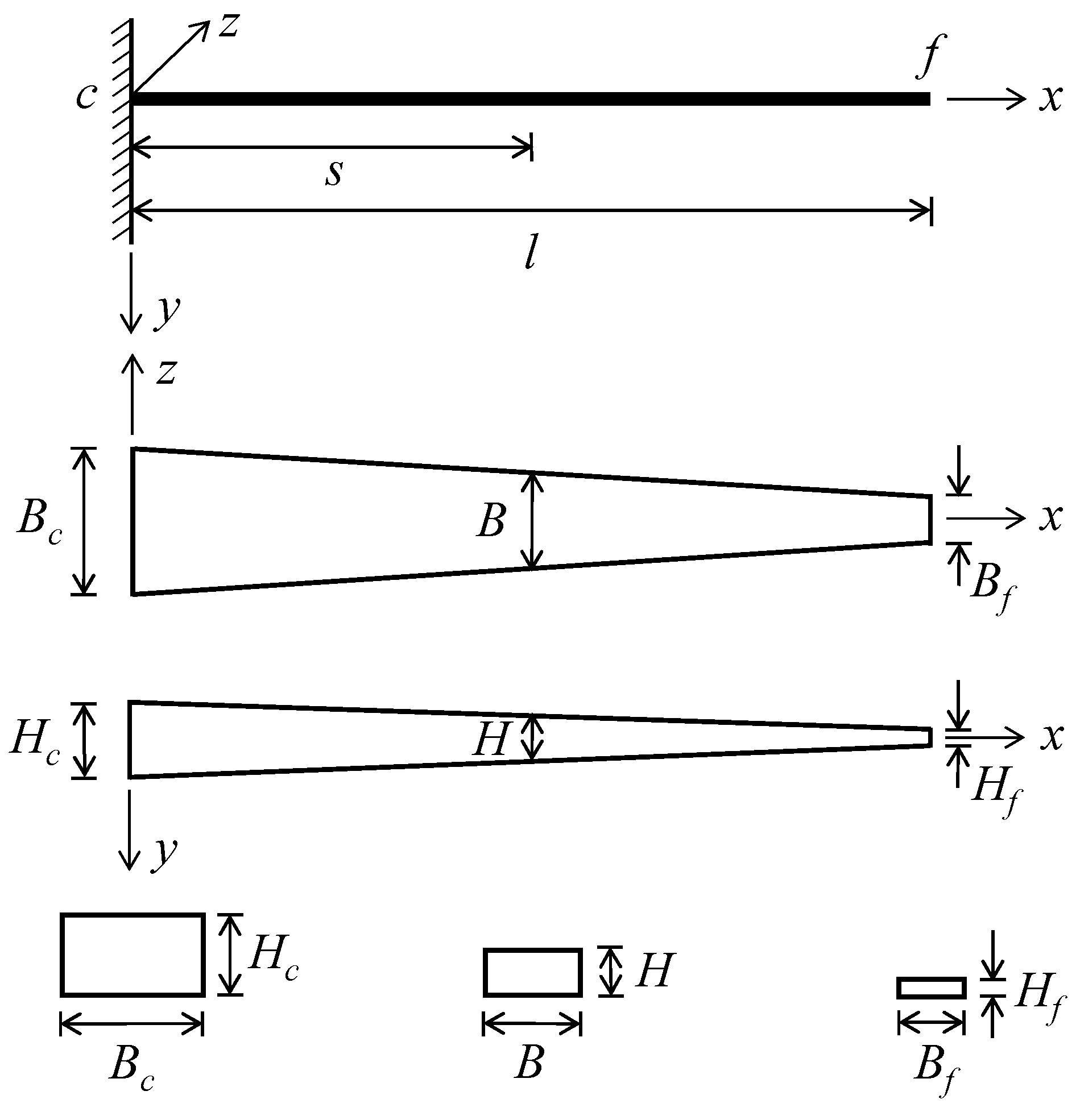
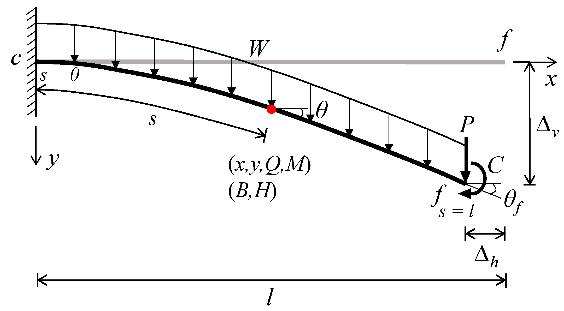
The symbols and loads for the cantilever beam are defined in
Figure 2. The beam was subjected to three types of loading, either individually or in combination: a uniform load
, tip point load
, and tip couple load
. The straight line
and solid curve
are the axes of undeflected and deflected (elastica) beams, respectively. The material point of the elastica at
is defined in Cartesian coordinates
, where the beam’s rotation is
and the shear force and bending moment are
and
, respectively. At the free tip
, the vertical displacement is
, horizontal displacement is
, and rotation angle is
.
In this study, the beam material was nonlinearly elastic with a stress–strain relationship defined by Ludwick’s constitutive law as follows:
where
and
represent the stress and strain, respectively, and
and
represent the Young’s modulus and exponential constant of the material, respectively. Note that the sign of
follows that of
.
The Bernoulli–Euler bending moment–curvature relationship for the rectangular beam with
and
fabricated from a Ludwick–type material can be written as follows [
8]:
where
is the curvature
of the elastica. The shear force
is expressed using the free body shown in
Figure 2 as follows:
Substituting Equations (3) and (4) into Equation (6) yields
where
The first derivative of Equation (7) with respect to
is obtained as follows:
Considering
,
is obtained from Equation (8) as
Substituting Equation (10) into Equation (9) yields the following ordinary differential equation:
The geometric relationships of the Bernoulli–Euler nonlinear beam are defined as follows:
Now, we consider the boundary conditions. At the clamped end
, no deflection occurs, resulting in
Note that the boundary condition of
at the clamped end is unknown, meaning Equations (11) and (12) cannot be solved as initial value problems. To calculate the unknown
as a boundary value problem, the boundary condition at the free tip
is considered. At the free tip,
in Equation (5) is equal to the tip couple loading
(i.e.,
), meaning
At the free tip,
and
are obtained from Equations (2) and (3) as follows:
Combining Equations (14) and (15) yields the following boundary condition at the free tip:
To facilitate numerical analysis, the load and geometry of the beam are cast into non-dimensional forms. First, the load parameters are defined as
The arc length
and coordinates
are normalized by the span length
as
The width and height at the clamped end are normalized by the length
as
The tip deflections
and
are normalized by the length
, and the tip angle parameter
is defined as follows:
Combining Equations (11) and (12) with the non-dimensional parameters in Equations (17)–(19) yields
where
The boundary conditions in Equation (13) at the clamped end
become
The boundary condition in Equation (16) at the free tip
becomes
Equations (21)–(25) represent fourth-order differential equations and boundary conditions that govern the elastica (i.e., large deformed shapes of beams) considered in this study.
5. Results and Comparisons
To analyze typical elastica behaviors, three beam materials were considered in this study: steel, the NP8 aluminum alloy, and annealed copper. For these materials, the values of the Young’s modulus and exponent constant to be introduced into Ludwick’s constitutive law are listed below.
- ■
Steel: GPa and .0
- ■
NP8 aluminum alloy: MPa and
- ■
Annealed copper: MPa and
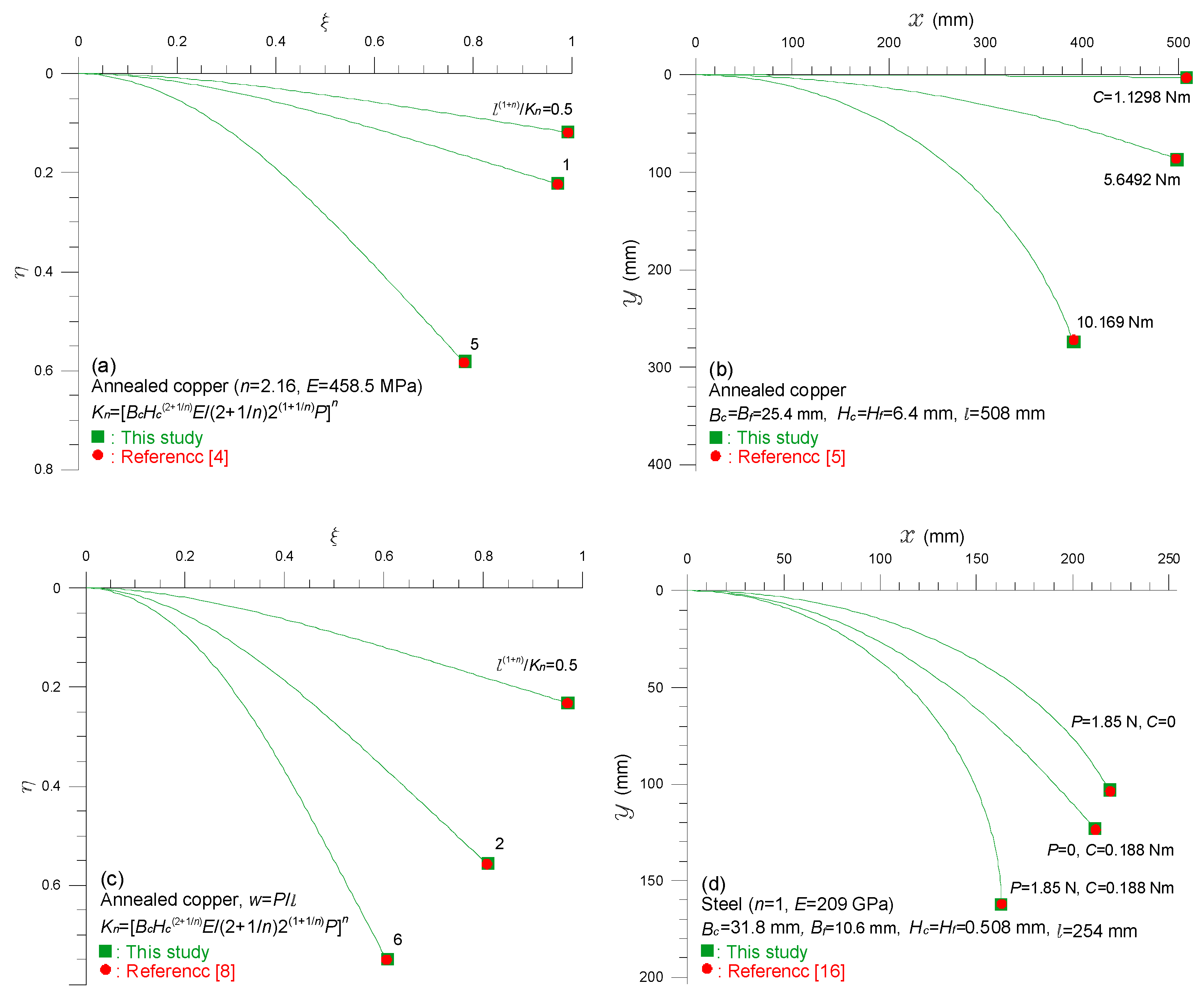
First, the results of this study are compared to those from the literature for degenerate cases, including non-prismatic, nonlinearly elastic, and combined loading effects, for validation purposes. The steel and annealed copper materials are considered in these comparisons.
Figure 3 presents comparisons between the tip responses
and
from this study and those from [
4,
5,
8,
16]. The beam parameters used for comparison are presented. The tip responses from this study (■) and those from the literature (●) are presented in the context of the elastica obtained in this study. Both sets of responses are in good agreement for the four degenerate cases. These comparisons validate the elastica theories and solution methods presented in this paper.
Next, we present parametric analysis of the elastica for various combinations of
,
, and
. The results for the annealed copper material (
) are presented in
Figure 3,
Figure 4 and
Figure 5. The beam parameters considered are also presented.
Figure 4 presents the tip responses of
versus the load curves (i.e., equilibrium paths) for three loading cases: (a) uniform load
, (b) tip point load
, and (c) tip couple load
. The trends appear as expected. Specifically, the relationships are strongly nonlinear and
all increase as the load increases. For the two loading cases of
and
, the angle parameter
converges to a value of
because the tip rotation
cannot physically reach
based on the vertical loading direction. However,
for load
can overcome this limitation and exceed
as
increases. Additionally, the physical meaning of
is one-cycle flip-over at the tip end, that of
is two-cycle flip-over, etc.
Typical examples of the elastica for a (a) uniform load
, (b) tip point load
, (c) tip couple load
, and (d) combined load with various load magnitudes are presented in
Figure 5. For all loading cases, the deflections of the elastica increase as the load increases. For the loading cases of (a)
and (b)
, one can see that the angle parameter
approaches one with an increasing load, which corresponds with the results in
Figure 3a,b. For the loading case of
(i.e., pure bending),
increases with an increasing
. Tip rotation occurs at one-cycle flip-over (i.e.,
) when
and at two-cycle flip-over (i.e.,
) when
(see loading combinations five and six). Additionally, the elastica under the negative couple load
are presented and show upward deflection with a negative curvature
(see loading combination seven). For the combined loading case (d), the deflections of the elastica for all seven loading combinations are presented. Load superposition increases the deflection compared to the sums of individual deflections. However, the superposition principle is not satisfied for the nonlinear elastic beams considered in this study. When comparing loading combinations four (
), seven (
), and eight (
), one can see that a positive
increases the deflection, and a negative
considerably reduces the deflections caused by the vertical loads
and
. Therefore, the elastica for loading combination eight show upward deflection beyond the horizontal axis.
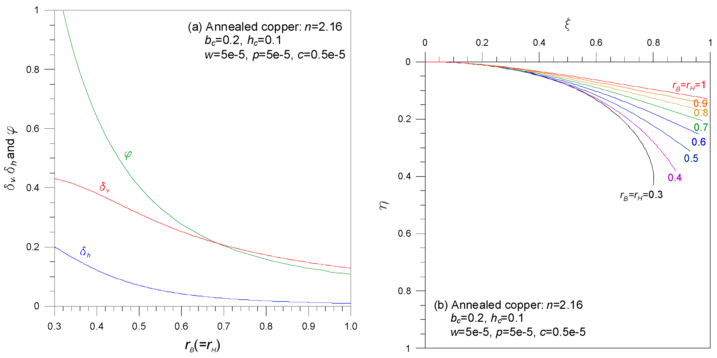
The effects of the cross-sectional ratio
on the three tip responses of
and the elastica are presented in
Figure 6 for the combined loading case with all of
. The beam parameters are included in the figure. In
Figure 6a, all the values of
decrease as
increases. The reduction rate is larger than that with the smaller cross-sectional ratio
From
Figure 6a, one can clearly see that the relationship between deflection and the cross-sectional ratio is strongly nonlinear, as indicated by the equilibrium paths in
Figure 4. Additionally, in
Figure 6b, the deflections of the elastica become deeper as
decreases.
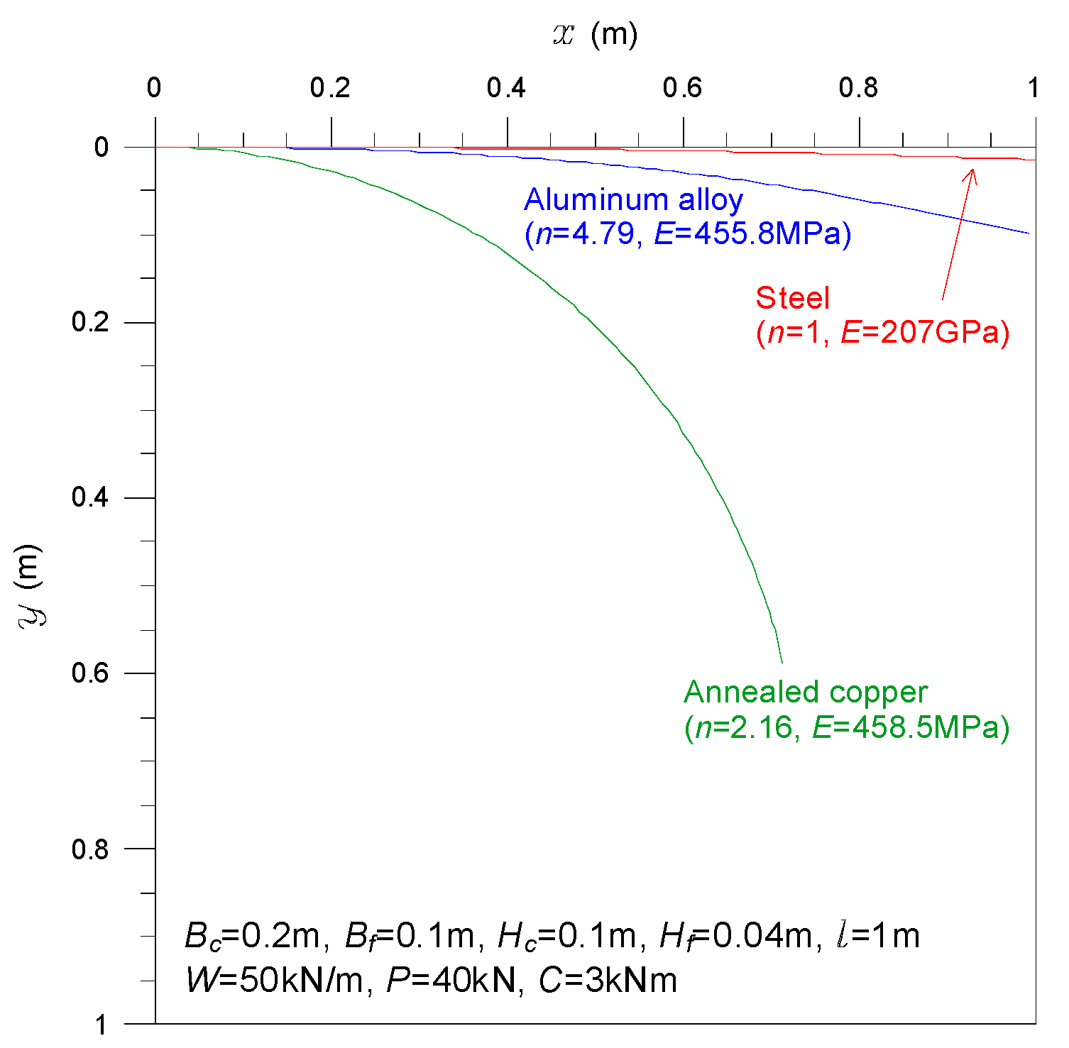
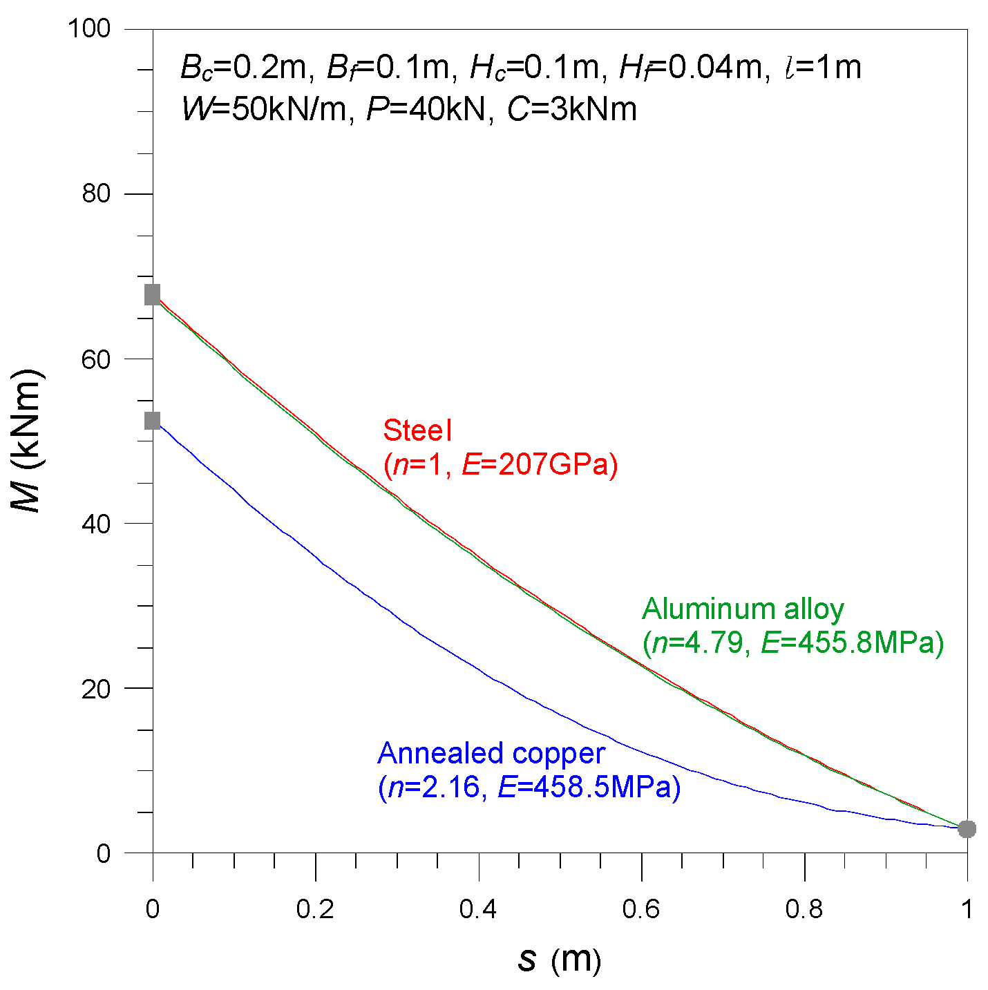
In a third series of experiments, the effects of beam materials on elastica were investigated. Three different beam materials, namely steel, the NP8 aluminum alloy, and annealed copper, were considered. The mechanical properties of and for these materials were provided above. For these parametric experiments, the numerical results are presented in dimensional units, rather than the nondimensional forms, because the load parameters of are different for the same load magnitudes with the same beam geometry for different materials. The consistent beam geometry and loading conditions for all three beam materials are listed below.
- ■
Beam geometry: 1 m, m, m, m, and m
- ■
Loading conditions: kN/m, kN, and kNm
For the reader’s convenience, the nondimensional forms of the beam parameters are listed below.
- ■
Beam geometry: , , , and
- ■
Loading conditions: , , and for steel; , , and for the NP8 aluminum alloy; and , , and for annealed copper.
Based on the beam parameters listed above, the elastica, bending moments, strains, and stresses of the clamped beam ends
were computed in the dimensional forms. The results are compared in
Figure 7,
Figure 8 and
Figure 9.
Figure 7 presents the deflections of the elastica for the three beam materials. One can see that deflections increase in the order of the annealed copper to the aluminum alloy to the steel. In particular, the deflections of the copper and aluminum beams are very different, despite the
values of both materials being nearly identical. From these results, we can conclude that the property of
, rather than
, has a dominant effect on the elastica.
Bending-moment diagrams along the beam axis for the three beam materials are presented in
Figure 8. One can see that the bending moments decrease from the steel to the aluminum to the copper. It is noteworthy that the bending moments of the steel and aluminum alloy are nearly identical, despite the two materials having very different values of
and
. In contrast, the bending moments of the aluminum alloy and annealed copper are very different. The
values of these two materials are nearly the same, but the
values differ significantly. From these results, we can conclude that both
and
have significant effects when calculating bending moments. Additionally, the maximum bending moments (■) occur at the clamped ends, whereas the minimum bending moments (
) occur at the free tips. These moments correspond to the tip couple loading
for all three materials.
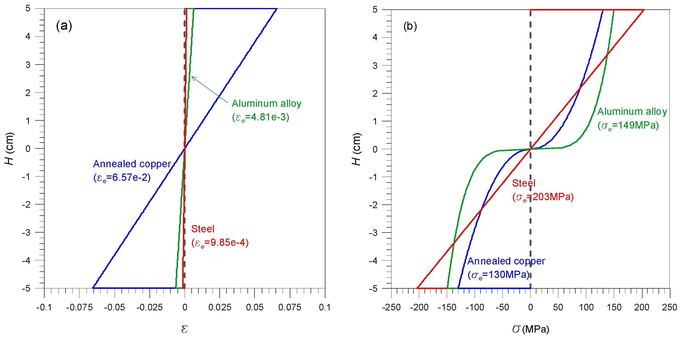
Figure 9 presents diagrams of the strains
and stresses
along the beam height at the clamped ends for the three beam materials. The strain
and stress
at a height
are computed as follows:
where
is the distance measured from the centroid along the vertical beam height.
By using the bending moments
(■ in
Figure 8) at the clamped ends (
) for the three beam materials, the strains
and stresses
were computed using Equations (29) and (30). The results for
and
are presented in
Figure 9a,b, respectively. For the reader’s convenience, the extreme values
and
on both sides of the beams (i.e.,
cm) in
Figure 9a,b are tabulated in
Table 1 along with the corresponding values of
, curvatures
, and mechanical properties
and
. The strains
along the height for the three beam materials are presented in
Figure 9a. The values of
decrease from the annealed copper to the aluminum alloy to the steel. Some unexpected patterns are visible in these results. For example, the strains of the steel and aluminum are nearly identical despite the two materials having very different
and
values. In contrast, the strains of the aluminum and copper are very different despite both materials having similar
values.
Figure 9b presents the stresses
along the beam height for the three beam materials. The values of
decrease from the steel to the aluminum to the copper. The stress distributions of the copper and aluminum near the neutral axis are relatively larger than that of the steel because their exponent constants are larger. However, one can see that the relationships between the stress
, and
and
are reversed compared to the strain relationships shown in
Figure 9a, which is an unexpected result (see
Table 1). From the results in
Figure 9 and
Table 1, we can conclude that the effects of
and
play important roles in computing the strain and stress of nonlinear elastic beams.


