Abstract
Deep in situ pressure coring provides an accurate means of determining oil and gas reserve parameters. The key to achieving pressure coring at depths exceeding 5000 m lies in the ultimate bearing strength and stability of the pressure controllers. Due to the limited downhole space and the inherent technical demands of pressure coring, traditional pressure coring technology typically has an ultimate bearing pressure capacity of less than 70 MPa. The structural model of the pressure controller is designed. The stress–strain distribution of the pressure controller under external load is numerically simulated. A contact stress optimization scheme and critical sealing gap of pressure controllers are proposed. It was found that the saddle pressure controllers can ensure the fit clearance of the sealing surface and effectively control the deformation of the valve cover within 0.015 mm. The saddle pressure controllers have demonstrated an ultimate bearing strength exceeding 140 MPa, with minimal leakage. These findings have significant implications for accurate assessment of deep petroleum resources.
1. Introduction
The sustainable exploration and development of deep resources are critical for advancing human society’s long-term sustainability [1]. As the social economy progresses, the demand for energy continues to rise, leading to the progressive exhaustion of shallow reserves [2]. Consequently, there is a growing need for humanity to explore and extract deep storage resources. In China, for instance, the extraction of coal resources has been steadily shifting to greater depths, with approximately more than 50% of the discovered coal resources now located over 1000 m underground [3]. The exploration of resources from deep areas has become a significant strategic priority for countries worldwide. Equally important is that natural gas hydrates (NGHs) are a treasure of resources bestowed upon humanity by nature [4,5]. It is widely found in continental permafrost and on continental margin seabeds. The estimated reserves of organic carbon in natural gas hydrate formations represent twice the cumulative quantity found in coal, oil, and natural gas combined [6]. And the recoverable global natural gas reserves are approximately 3 × 10¹³ m3 [7,8]. Precise assessment of natural gas hydrate reserves and evaluation of their fundamental physical and mechanical characteristics are essential for achieving reliable pilot extraction and subsequent large-scale development [9]. Nevertheless, a critical consideration is that the properties of NGHs are highly sensitive to external environmental changes and can only exist under specific conditions (as shown in Figure 1).
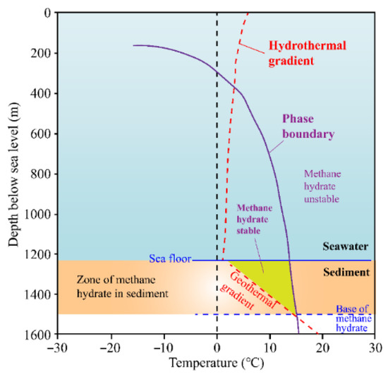
Figure 1.
Phase diagram of deep-sea natural gas hydrates [10].
Therefore, maintaining consistency between the external environment and the subterranean reservoir conditions is essential throughout the drilling, coring, extraction, and testing processes. Currently, acquiring the inherent physical–mechanical characteristics of reservoir-hosted natural gas hydrates under true in situ conditions continues to present significant difficulties, which hampers our understanding of reservoir stability and occurrence patterns. However, there have been significant advancements and innovations in deep in situ coring and testing techniques that now allow us to obtain in situ physical property patterns of deep-sea natural gas hydrates. Pressure coring, for instance, is a core retrieval technique that preserves the original formation pore pressure, enabling the preservation of in situ properties of NGHs. In contrast, conventional coring tools lack pressure-conservation mechanisms, making it difficult to obtain cores that accurately reflect the in situ pressure environment [11,12]. The application of pressure coring techniques is depicted in Figure 2.
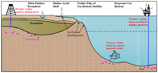
Figure 2.
Applications of pressure coring techniques.
2. Challenges in Pressure—Pressure Coring Technology
Deep in situ pressure coring serves as a fundamental aspect for accurately assessing deep-sea resource reserves [13]. As resource exploration delves deeper, deep drilling encounters extreme conditions of high temperature and high pressure, sometimes exceeding 100 MPa [14], which presents significant challenges to the safety and feasibility of pressure coring. This necessitates the advancement of pressure-preserving coring systems capable of maintaining consistent performance and reliable functionality under high-pressure conditions [15]. Numerous countries worldwide have undertaken research on pressure coring technology [16,17,18,19,20].
The success of the pressure preservation coring technique hinges on the structural design and performance of the pressure control system. The Ocean Drilling Program technical report [21] highlights that the primary and most fundamental challenge lies in finding better solutions for “closing the door” after core retrieval. Despite years of application testing and practical verification, there are still prevalent technical difficulties that require urgent resolution. (1) The ability of pressure preservation coring needs to be further improved. The pressure control system, as the crucial mechanism that seals the core in the pressure cylinder, determines the maximum bearing capacity of the pressure preservation coring devices. The pressure-bearing capacity of the PCS units exhibits 70 MPa pressure resilience, while the PCB/PCTB have a pressure resistance strength of 35 MPa. PTCS and PTPS have a pressure resistance strength of 30 MPa, FPC and HRC have a pressure resistance strength of 25 MPa, and PTPC and DAPC have a pressure resistance strength of 20 MPa. Nonetheless, deep drilling operations encounter extreme conditions characterized by high temperatures and pressures (even surpassing 150 °C, 100 MPa), which present significant obstacles to pressure preservation coring. Consequently, it is imperative to conduct research on the mechanical behavior of pressure preservation coring controllers in deep in situ environments, optimize the design of pressure control controller configurations, and enhance their ultimate pressure resistance strength. These initiatives prove essential to fulfill emerging needs in deep-earth research and subsurface resource discovery. (2) It is essential to enhance our understanding of the failure mechanisms associated with in situ pressure preservation coring controllers during deep drilling. The extreme environmental conditions encountered in deep drilling present substantial challenges to the pressure preservation performance of coring controllers. The failure of pressure preservation controllers can be attributed to various factors, as stated in the PCS technology report. The efficacy of pressure-preserved core acquisition is perpetually undermined by inherent design flaws, contaminant ingress, sealing element failures, and corrosion phenomena within valve assemblies. Inherent design flaws, contaminant ingress, sealing element failures, and corrosion phenomena within valve assemblies have consistently posed challenges to the success rate of pressure preservation coring. The non-uniform structural deformation caused by pressure fluctuations during coring operations presents difficulties in maintaining a proper seal for the pressure controller. Consequently, over 30% of pressure core samples either experience a loss of pressure or only retain partial pressure on-site. It is crucial to delve into the theoretical aspects of pressure controllers, with a focus on critical deformation characteristics, in order to understand the failure mechanisms. This knowledge can then serve as guidance for the structural design and optimization of material strength, effectively preventing potential failures and enhancing the overall design and performance of pressure controllers.
Achieving technological breakthroughs in deep-sea mining depends fundamentally on innovating resource localization and extraction processes. It is essential to enhance and optimize the key structures of pressure controllers to improve their operational capabilities in complex environments. Currently, the existing core sampling techniques in deep and complex environments still require improvement in terms of applicability and stability. There are multiple potential failure modes that can result in issues such as contamination of pressure core samples, pressure loss, and low success rates. The success rate and stability of pressure core sampling heavily rely on the structural design and performance optimization of the pressure controller. This article focuses on the operational mechanisms of deep formation pressure-core acquisition, with a particular emphasis on the intrinsic relationship between configuration design, material selection, and the hermetic endurance metrics governing the pressure regulation module. The objective is to design and develop a high-strength pressure controller. Through the use of a self-developed testing platform for laboratory simulations, this study investigates the mechanical behavior of the pressure controller at disparate pressures, aiming to gain a deeper understanding of the underlying causes of pressure controller failures. By establishing an optimization design scheme, it is possible to refine and hold substantial potential for augmenting the controller’s systemic functionality.
3. The Theoretical Model’s Construction and Structural Optimization of the Pressure Controller
Drawing upon the Steinmetz solid principles [22] for deep in situ pressure core sampling, this configuration exploits the annular region within the core barrel’s dual-tubing system to engineer a pressure-retaining sampler optimized for spatially constrained deep drilling environments. The core sampler is composed of a suspension assembly, measurement module, pressure control module, and differential module (as shown in Figure 3). The primary function of the pressure module is to automatically seal when the core is inserted into the sampler. It comprises a pressure controller (valve cover, valve seat, connectors), spring sleeve, spring, pressure outer tube, accumulator, and sealing components.
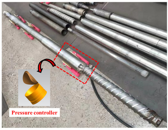
Figure 3.
Prototype of deep in situ pressure coring tools.
As a pivotal component in pressure-retained coring systems, the pressure controller’s architectural configuration and functional efficacy govern system integrity. This mechanism operates as a seal valve, isolating cores at the pressure vessel base, thereby dictating the sampler’s peak load tolerance. Different pressure controller configurations, such as PCTB, PCS, PCB, PTCS, Hybrid PCS, and DAPC, utilize ball valve structures to ensure compatibility with bottom-hole assembly tools. On the other hand, FPC, HRC, PTPC, PTPS, and MAC employ flapper valve structures. It is worth noting that under high-pressure conditions, variations in physical and geometric parameters among different pressure controller configurations can result in varying levels of deformation and fluctuations in contact pressure. These factors have a direct impact on the overall pressure performance of the system.
Investigating the mechanical behaviors of different pressure controller configurations under deep in situ conditions is crucial for achieving effective pressure coring at varying depths. Initial research yielded five pressure-regulating mechanisms predicated upon Steinmetz solid geometry and depth-specific coring device design criteria (as shown in Figure 4). These structures were developed using a geometric model of intersecting hollow cylinders and cones. However, it is important to note that current pressure core capabilities are insufficient for depths exceeding 3000 m. Therefore, further optimization of the pressure controller’s design and material selection is needed, drawing on previous technical experiences.
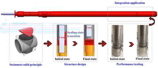
Figure 4.
Components of deep in situ pressure preservation coring.
The pressure regulator’s intricate structural configuration and nonlinear deformation behavior necessitate modeling simplifications for effective analysis. Utilizing the fundamentals of elasticity and the Kirchhoff–Love assumptions, differential equations for thin shells are established to determine stress and displacement.
When the bending stiffness of the thin shell or the changes in curvature and torsion at the mid-surface are extremely small, bending moments and torsional moments can be considered negligible. Therefore, when analyzing the equilibrium of thin shells, the influence of bending stresses on structural balance is ignored. Although this theory does have errors in calculating the deformation under the critical state, it is convenient for calculation and applicable to application analysis under engineering conditions. It is assumed that there are no bending moments and torsional moments on all cross-sections of the thin shell, resulting in a state of zero moment stress. A coordinate system is established as shown in Figure 5.
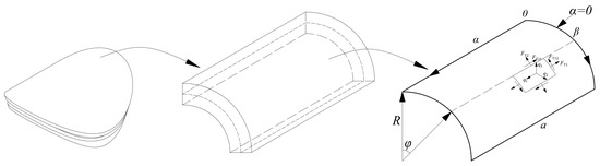
Figure 5.
Simplified structural model.
According to the equilibrium equation of zero moment, we have
According to the equation of zero moment elasticity, we have
The loading and boundary conditions are as follows,
Thus, the solution is obtained,
By substituting the parameter values, , , , , we obtain,
Thus, under an external load of 140 MPa, the maximum displacement is 1.17 × 10⁻⁴ m at the middle of the valve cover. Notably, the model requires both ends to be free from normal and rotational constraints, with no moment of internal forces to be achieved. Additionally, the pressure distribution on the valve seat indicates a concentration of pressure at the base of the saddle-supported step, resulting in shear forces. If this exceeds the yield limit of the material, it may potentially lead to structural failure.
Post-structural verification, a controller’s peak pressure containment capacity is predominantly governed by seal integrity [23]. By examining the weak sealing areas of the short-axis wings, it is possible to correlate the deformation with the critical sealing gap in order to estimate the critical load of the controller.
Wm is the displacement at the minor axis end of valve cover.
4. Numerical Simulations of Stress–Strain Characteristics for Deep In Situ Pressure Controller
Due to the high-pressure state in which the pressure controller operates inside the corer, it becomes challenging to obtain effective data, often likened to a “dark box” situation. Fortunately, numerical simulation provides a method for simulating the mechanical behavior of the pressure controller. The stress distribution and strain response of the pressure-regulation mechanism are examined in this research using ABAQUS finite-element analysis.
Figure 6 displays the saddle-contoured controller’s geometric solid model, and a hexahedral mesh is generated based on its actual dimensions. Nominal stress–strain curves of 304 steel at various temperatures, derived from high-temperature tensile tests, are converted to true stress–strain curves and applied to the geometric model of the pressure controller. To ensure mesh independence, a 1/4 section model is refined into different mesh sizes: 20,430, 26,862, 52,306, 80,496, and 132,760 elements. The mesh independence is assessed based on parameters such as maximum stress, minimum stress, maximum displacement, and minimum displacement, as illustrated in Figure 7 and Table 1. Computational outcomes demonstrate that beyond 52,306 elements, the variation in these four key parameters becomes minimal, providing a critical reference for mesh division.
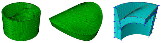
Figure 6.
Mesh division and boundary conditions for the pressure controller.
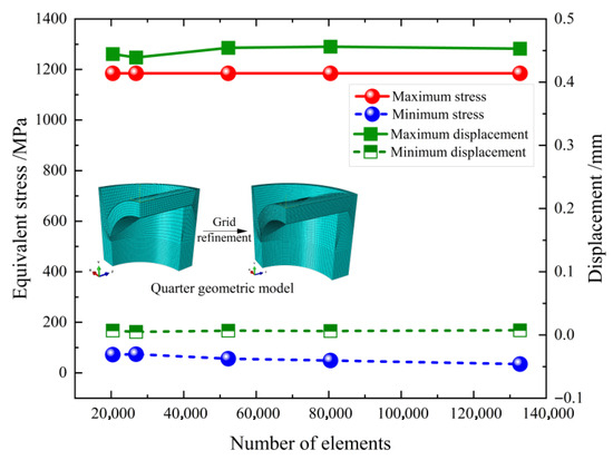
Figure 7.
Mesh sensitivity analysis.

Table 1.
Parameter differences under different element count conditions.
Consequently, the simulation is carried out in four load steps: Step 1 involves the assembly of the valve cover and seat, Step 2 deals with the pre-contact between them, Step 3 encompasses the gradual increase in external pressure to 100 MPa, and Step 4 involves further increasing it to 140 MPa. Finite-element analysis revealed peak stresses up to 1185 MPa, primarily concentrated at the ends of the valve cover’s minor axis. Under increasing load conditions, displacement maxima at the valve cover’s minor-axis termini reach 0.015 mm, as documented in Figure 8. The saddle-profile bracing interface critically governs deformation containment at the valve cover periphery. It serves as a key element in restricting the deformation of the sealing face and acts as the primary structure for bearing pressure. Additionally, the pressure distribution on the valve seat indicates a concentration of pressure at the base of the saddle-supported step, resulting in shear forces. If this exceeds the yield limit of the material, it may potentially lead to structural failure, as illustrated in Figure 9.
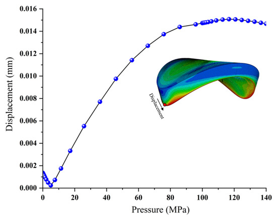
Figure 8.
Deformation of the minor axis of the pressure controller.
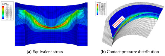
Figure 9.
Contact pressure of the valve seat.
Shear resistance deficiency poses risks for E-type pressure controllers. Given the dimensional constraints of the coring apparatus, the saddle-base step exhibits reduced thickness and may fail under 200 MPa loading. To address this, a geometric model of an E-type controller was designed based on size requirements, and a numerical simulation model was established, as shown in Figure 10. A hexahedral mesh was used, with the bottom of the valve seat fully fixed and hydrostatic pressure applied to the top of the valve cover. Utilizing hexahedral meshing, the valve seat base remained fully constrained with hydrostatic pressure applied to the valve cover top. Significant stress concentrations surpassing material tensile strength occurred at the saddle-base’s short-axis edge. Optimization strategies involve modifying the valve cover’s minor-axis contour and strengthening the valve seat material.
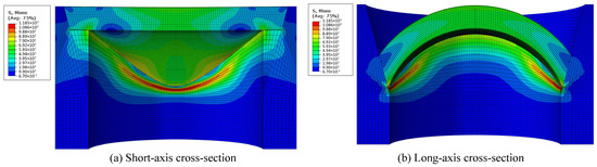
Figure 10.
Mises stress distribution of the E-type pressure controller.
5. Physical Test of Ultimate Pressure Strength for Core Controllers
5.1. Experimental Procedure
The study develops a pressure-preserved coring test platform, which is constructed based on actual parameters (refer to Figure 11). This platform consists of a control system, pressurization system, test chamber, and monitoring system. The primary experimental steps include: (1) Inspect the sealing ring for wear and check for leaks in the pressure controller. Connect the strain monitoring system using a 1/4 bridge with a strain gauge, incorporating a common compensation terminal for temperature compensation. Set storage rules and sampling frequency. The position of strain gauges under the pressure controller valve cover, according to numerical simulation results, is shown in Figure 12. SG-A marks the equivalent stress concentration area, SG-B the large deformation area, SG-C the edge of stress concentration, and SG-D the long axis edge, with SG-E supplementing SG-C. (2) Experimental procedures commence by mounting the pressure controller at the test chamber bottom, then positioning a preloaded spring atop it to establish initial sealing pressure. Use lifting tools to install the test container and secure the container bracket with fasteners. Then, initiate water flow by opening the pipeline and valve assembly, activate the hydraulic pump to pressurize the chamber with water, and release air to prevent excessive pressure buildup. (3) Engage the booster pump and valve to elevate pressure in 5 MPa increments, sustaining each pressure level for approximately 20 min. Apply pressure through the upper inlet until the pressure controller’s seal fails. (4) Shut down the booster pump and compressor, open the relief valve, and drain the water from the pressure chamber. Then, open the chamber, remove the pressure controller, and collect and save the test data.
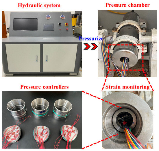
Figure 11.
Pressure core laboratory testing platform.
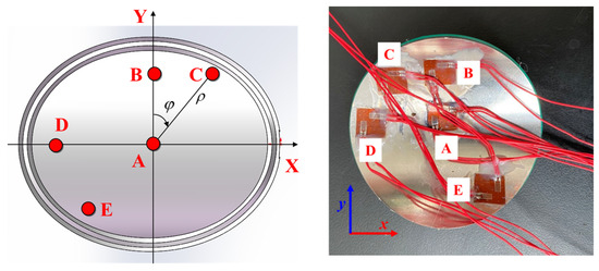
Figure 12.
Strain measurement point.
5.2. Experimental Results
Using the pressure coring test platform, we conducted tests of the ultimate bearing capacity of saddle-type pressure controllers made from various materials. The ultimate pressure resistance test results for E-type controllers made of four typical materials are displayed in Figure 13.
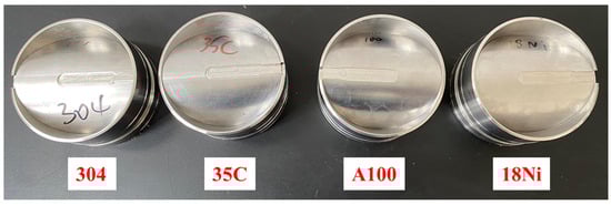
Figure 13.
Pressure controllers of different materials.
Figure 14a displays the deformation characteristic curve for the 18Ni E-type pressure controller. The controller demonstrates effective pressure retention by maintaining stable pressure above 140 MPa for over 4.6 h. As the pressure increases, there are significant fluctuations in strain. At 140 MPa, the strain fluctuation amplitude and magnitude of the pressure controller are notably higher compared to other configurations. In the X direction, tensile strain is predominant, while in the Y direction, compressive strain dominates. The greatest increase in tensile strain is observed in EX, indicating significant deformation at the bottom surface of the valve cover. AX, BX, and CX also experience considerable tensile strain growth. EY exhibits the largest compressive strain fluctuation at −2.5085 × 10⁻², followed by BY and CY, with AY showing minimal change.
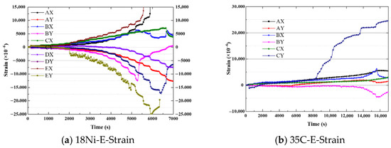
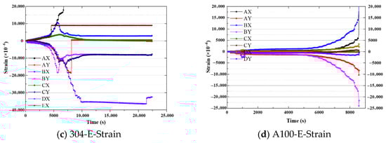
Figure 14.
Deformation characteristics for E-type controllers with different materials.
The deformation characteristic curve for the E-type pressure controller made of 35CrNi3MoVR material is depicted in Figure 14b. This pressure controller exhibits an almost negligible leakage rate. It is capable of maintaining stable pressure for more than 15.1 h at 140 MPa, which indicates its effectiveness in retaining pressure. As the pressure increases, there are notable fluctuations in strain, particularly at 140 MPa. Tensile strain dominates in the X direction, while compressive strain prevails in the Y direction. AX, BX, and CX experience primarily tensile strain, while AY and BY are predominantly subjected to compressive strain. Furthermore, as the pressure increases, the strain in CY transitions from compressive to tensile.
The E-type pressure controller made of 304 material showcases an almost negligible leakage rate and maintains stable pressure for over 3.1 h at 140 MPa, indicating effective pressure retention. The deformation characteristic curve, illustrated in Figure 14c, demonstrates noticeable strain fluctuations with increasing pressure. Specifically, at 140 MPa, there is a significant strain fluctuation, with tensile strain observed in the X direction and compressive strain observed in the Y direction. AX, BX, and CX experience tensile strain, while AY, BY, and CY experience compressive strain. The strain remains stable at 140 MPa.
The E-type pressure controller made of A100 material exhibits an almost negligible leakage rate, indicating effective pressure retention. The deformation characteristic curve presented in Figure 14d demonstrates an increase in strain fluctuations as the pressure rises. In the X direction, tensile strain dominates, whereas in the Y direction, compressive strain is more prominent. AX, BX, CX, and DX experience tensile strain, while AY, BY, CY, and DY undergo compressive strain. Among the tensile strains, BX shows the largest fluctuation at 2.185 × 10⁻², followed by AX at 7.539 × 10⁻³ and DX at 3.343 × 10⁻³. For compressive strains, BY exhibits the largest fluctuation at −2.40 × 10⁻², followed by AY with a maximum of −1.03 × 10⁻² under extreme load, while CY and DY show minor changes.
In general, the strain patterns of E-type pressure controllers are similar across different materials, with slight variations in strain magnitude. All four materials exhibit excellent pressure retention even under high-pressure conditions, maintaining low leakage rates. Test results indicate that the ultimate pressure strength exceeds 140 MPa for 18Ni, 35CrNi3MoVR, and 304 materials, while A100 material has an ultimate strength of 129.4 MPa. In terms of structural integrity, the 35CrNi3MoVR material demonstrates smaller deformation, making it suitable for repeated use in engineering applications. The leakage rates for 18Ni, 35CrNi3MoVR, 304, and A100 materials approach 0 MPa/s at all pressure stages, indicating minimal leakage. Significant stress concentration manifests at the saddle-shaped base step’s short axis, exceeding the material’s tensile strength. This observation is supported by physical experiments that demonstrate crushing (as shown in Figure 15 and Figure 16). Structural modifications to the valve cover’s short-axis edge, coupled with reinforcement of the valve seat material, enable resolution of this condition.
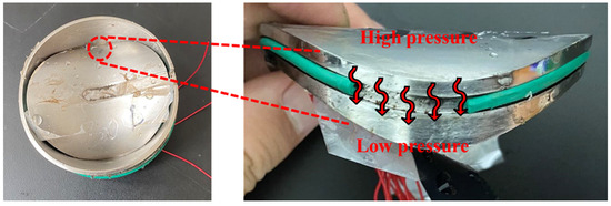
Figure 15.
Sealing failure of pressure controllers.
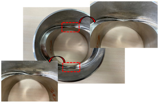
Figure 16.
The E-type pressure controller under 140 MPa conditions.
6. Conclusions
The main conclusions are as follows:
- (1)
- The results of numerical simulation and theoretical calculation show that one of the causes for the failure of the pressure-bearing capacity of the pressure-holding controller is the shear failure at its short axis. The suppression of valve cover deformation and the optimization of the sealing structure are the keys to developing a pressure-holding controller.
- (2)
- The optimized saddle-shaped pressure controller effectively limits valve cover deformation to within 0.015 mm, ensuring proper sealing surface clearance. The maximum pressure-bearing capacity of the pressure controller is constrained by the deformation and sealing of its short axis. Shear failure of the saddle-shaped step is identified as the primary cause of failure. To enhance load capacity, high-strength materials could be utilized.
- (3)
- The 35CrNi3MoVR material saddle-shaped pressure controller shows optimal capacity, with a pressure strength exceeding 140 MPa and maintaining this strength for at least 15.1 h, while also exhibiting near-zero leakage. These findings provide support for pressure core sampling in oil and gas exploration at depths exceeding 5000 m.
Author Contributions
Writing—original draft preparation, C.L.; writing—Review and editing, X.S.; software, X.F.; validation, X.Y.; formal analysis, J.L.; supervision, L.Z. All authors have read and agreed to the published version of the manuscript.
Funding
This research was supported by Deep Earth Probe and Mineral Resources Exploration-National Science and Technology Major Project (2024ZD1003901), the National Natural Science Foundation of China (52304146, 524B2040), and the Guangdong Provincial Key Laboratory Foundation (DESGEEU-2023-2).
Data Availability Statement
The data presented in this study are available on request from the corresponding author due to privacy.
Conflicts of Interest
The authors declare no conflicts of interest.
References
- Shi, X.J.; Xie, H.P.; Li, C.; Liu, G.K.; Gao, M.Z. Design of a high-performance pressure-preserving controller for in situ pressure-preserving coring in deep oil and gas extraction. J. Rock Mech. Geotech. Eng. 2025, 17, 5038–5052. [Google Scholar] [CrossRef]
- Xie, H.P.; Gao, M.Z.; Zhang, R.; Zhou, H.W.; Gao, F.; Chen, L.; Peng, R.D.; Li, X.J.; Ju, Y. Application prospects of deep in-situ condition-preserved coring and testing systems. Adv. Geo-Energy Res. 2024, 14, 12–24. [Google Scholar] [CrossRef]
- Wang, J.; Xie, H.P.; Li, C. Anisotropic failure behaviour and breakdown pressure interpretation of hydraulic fracturing experiments on shale. Int. J. Rock Mech. Min. Sci. 2021, 142, 104748. [Google Scholar] [CrossRef]
- Ray, B.; Timothy, S.C. Current perspectives on gas hydrate resources. Energy Environ. Sci. 2011, 4, 1206–1215. [Google Scholar]
- Milko, A.V.; Sassen, R. Preliminary assessment of resources and economic potential of individual gas hydrate accumulations in the Gulf of Mexico continental slope. Mar. Petrol. Geol. 2003, 20, 111–128. [Google Scholar] [CrossRef]
- Piñero, E.; Marquardt, M.; Hensen, C.; Haeckel, M.; Wallmann, K. Estimation of the global inventory of methane hydrates in marine sediments using transfer functions. Biogeosciences 2013, 10, 959–975. [Google Scholar] [CrossRef]
- Nguyen, N.N.; Nguyen, A.V. The dual effect of sodium halides on the formation of methane gas hydrate. Fuel 2015, 156, 87–95. [Google Scholar] [CrossRef]
- Koh, D.Y.; Ahn, Y.H.; Kang, H.; Park, S.; Lee, J.Y.; Kim, S.J.; Lee, J.; Lee, H. One-dimensional productivity assessment for on-field methane hydrate production using CO2/N2 mixture gas. AIChE J. 2015, 61, 1004–1014. [Google Scholar] [CrossRef]
- Chong, Z.R.; Yang, S.H.B.; Babu, P.; Linga, P.; Li, X.S. Review of natural gas hydrates as an energy resource: Prospects and challenges. Appl. Energy 2016, 162, 1633–1652. [Google Scholar] [CrossRef]
- Kvenvolden, K.A. Methane Hydrate—A major reservoir of carbon in the shallow geosphere. Chem. Geol. 1988, 71, 41–51. [Google Scholar] [CrossRef]
- Xie, H.P.; Hu, Y.Q.; Gao, M.Z.; Chen, L.; Zhang, R.; Liu, T.; Gao, F.; Zhou, H.W.; Peng, X.B.; Li, X.J.; et al. Research progress and application of deep in-situ condition preserved coring and testing. Int. J. Min. Sci. Technol. 2023, 33, 1319–1337. [Google Scholar] [CrossRef]
- Xie, H.P.; Liu, T.; Gao, M.Z.; Chen, L.; Zhou, H.W.; Ju, Y.; Gao, F.; Peng, X.B.; Li, X.J.; Peng, R.D. Research on in-situ condition preserved coring and testing systems. Petrol. Sci. 2021, 18, 1840–1859. [Google Scholar] [CrossRef]
- Shi, X.J.; Xie, H.P.; Li, C.; Liu, G.K.; Wei, Z.J.; Wang, T.Y.; Li, J.; Li, Q.Y. Influence of the mechanical properties of materials on the ultimate pressure-bearing capability of a pressure-preserving controller. Petrol. Sci. 2024, 21, 3558–3574. [Google Scholar] [CrossRef]
- Lei, L.; Park, T.; Jarvis, K.; Pan, L.; Tepecik, I.; Zhao, Y.; Ge, Z.; Choi, J.; Gai, X.; Sergio, A.G.T.; et al. Pore-scale observations of natural hydrate-bearing sediments via pressure core sub-coring and micro-CT scanning. Sci. Rep. 2022, 12, 3471. [Google Scholar] [CrossRef] [PubMed]
- Shi, X.J.; Xie, H.P.; Li, C.; Li, J.N.; Liu, G.k.; You, Z.X.; Gao, M.Z. Performance of a deep in situ pressure-preserving coring controller in a high-temperature and ultrahigh-pressure test system. J. Rock Mech. Geotech. Eng. 2025, 17, 877–896. [Google Scholar] [CrossRef]
- Ashena, R.; Thonhauser, G. Coring Methods and Systems; Springer: Berlin/Heidelberg, Germany, 2018. [Google Scholar]
- Demirbaş, A. Methane hydrates as potential energy resource: Part 1-Importance, resource and recovery facilities. Energy Convers. Manag. 2010, 51, 1547–1561. [Google Scholar] [CrossRef]
- Xu, Z.; Hu, T.; Pang, X.Q.; Wang, E.Z.; Liu, X.H.; Wu, Z.Y.; Chen, D.; Li, C.R.; Zhang, X.W.; Wang, T. Research progress and challenges of natural gas hydrate resource evaluation in the South China Sea. Petrol. Sci. 2022, 19, 13–25. [Google Scholar] [CrossRef]
- Kvenvolden, K.; Cameron, D. Pressure Core Barrel: Application to the Study of Gas Hydrates, Deep Sea Drilling Project Site 533, Leg 76; Initial Reports of the DSDP; Texas A&M: College Station, TX, USA, 1983. [Google Scholar]
- Dickens, G.; Wallace, P.J.; Paull, C.; Borowski, W.S. Detection of methane gas hydrate in the Pressure Core Sampler (PCS): Volume-pressure-time relations during controlled degassing experiments. Proc. Ocean. Drill. Program Sci. Results 2000, 164, 113–126. [Google Scholar]
- Ruppel, C.; Boswell, R.; Jones, E. Scientific results from Gulf of Mexico Gas Hydrates Joint Industry Project Leg 1 drilling: Introduction and overview. Mar. Petrol. Geol. 2008, 25, 819–829. [Google Scholar] [CrossRef]
- Peterson, M.N. Design and Operation of a Wireline Pressure Core Barrel; Technical Report; Deep Sea Drilling; Scripps Institution of Oceanography: La Jolla, CA, USA, 1984. [Google Scholar]
- Li, C.; Xie, H.P.; Gao, M.Z.; Chen, L.; Li, J. Novel designs of pressure controllers to enhance the upper pressure limit for gas-hydrate-bearing sediment sampling. Energy 2021, 227, 120405. [Google Scholar] [CrossRef]


Disclaimer/Publisher’s Note: The statements, opinions and data contained in all publications are solely those of the individual author(s) and contributor(s) and not of MDPI and/or the editor(s). MDPI and/or the editor(s) disclaim responsibility for any injury to people or property resulting from any ideas, methods, instructions or products referred to in the content. |
© 2025 by the authors. Licensee MDPI, Basel, Switzerland. This article is an open access article distributed under the terms and conditions of the Creative Commons Attribution (CC BY) license (https://creativecommons.org/licenses/by/4.0/).