Abstract
In this work, a decentralized robust direct model reference adaptive controller (MRAC) via e-modification is suggested for the pose control of a quadrotor to prevent parameter drift. The governing equations of motion referred to the rotational system of the quadrotor are parameterized involving matched uncertainties through the control input channel in a decentralized way from the angles of motion, where bounded perturbations are also considered. An error-dependent damping term in the update law is added to enforce robustness. Uniform ultimate boundedness of the tracking error signal is ensured. The translational dynamics are governed through a linear proportional–integral–derivative (PID) control. The performance of the decentralized robust MRAC scheme proposed here is assessed via simulation and compared with that from decentralized robust MRACs using smooth dead-zone modification and -modification.
1. Introduction
From experience, it is well-known that when the system output is influenced by uncontrolled inputs, and not only by the control input, such inputs cause disturbances affecting the system in unpredictable ways although these may be present for a limited time.
The design of stable adaptive controllers is the main issue when trying to achieve asymptotic model following. Unbounded solutions could emerge with unmodeled dynamics and time-varying parameters as perturbations [1]. To this last eventuality, certain performance conditions must be satisfied through the control design task having as a main goal the boundedness for all the signals from the closed-loop system [2,3,4,5].
In this work, in order to assure stability in presence of uncontrolled inputs and modeling errors in the decentralized adaptive control for the pose of a quadrotor unmanned aerial vehicle (UAV), modifications to the parametric estimation algorithm (update law) are examined, which leads to robust learning algorithms. A robust learning algorithm is characterized by preserving, within some specifications of design, stability properties under external perturbations and model uncertainties [2,3,6]. It is well known that conventional adaptive (update) laws show parameter drift in the presence of external perturbations, unmodeled dynamics, measurement noise and time variations. The parameter drift is an anomaly in which the parametric estimates go far from their ideal values, possibly to infinity. Parameter drift may be an eventuality when the online parametric estimator does not have any value for the parameters from a matching condition. Also, in the presence of a small amount of measurement noise and high-frequency unmodeled dynamics, if the input signal does not satisfy the so-called persistency of excitation property, in other words, if it is not sufficiently rich, the parametric estimates do not converge to their ideal values, which could mean that these may also drift with output of the system suddenly diverging abruptly [7].
Two alternatives can be addressed in order to evade parameter drift. The first one, the well-known dead-zone modification [4], is suggested when the training error is too small, which consists of not performing parametric adaptation. The last one, through the use of the so-called e-modification [8,9], -modification [5], also known as the leakage factor [2], and projection algorithms [2,10,11,12] shifts the online parametric estimator such that the parametric estimates are constrained from the drift to infinity.
The e-modification has been developed [8] in order to overcome a limitation with the -modification in that it can achieve asymptotic tracking under certain conditions while improving robustness. The aim of the e-modification is to reduce the damping term proportionally to the tracking error norm. The damping term is reduced to zero as the tracking error tends to zero, giving back the asymptotic tracking property of the ideal case with model reference adaptive control (MRAC). Nevertheless, the e-modification only achieves bounded tracking in accordance with the stability analysis, so the ideal property of the MRAC is not preserved. Moreover, asymptotic tracking is not attained in general with increased robustness.
In [13], HIL simulation and flight test results were shown about the performance from both conventional MRAC and MRAC with e-modification in the control of a SIG Rascal 110 UAV. It should be noticed that for flight tests, the commands from the adaptive controller were limited by the autopilot to avoid undesirable attitudes that might lead to the loss of the UAV. Flight test results showed a similar performance as that from HIL results, i.e., degradation of the performance of the closed-loop system was exhibited when adding the damping term in the update law, although parameter drift was avoided. Authors claim that similar results were observed for the MRAC with -modification and a projection operator, although these results were not shown in their work. Also, authors claim that the performance of the MRAC with e-modification could be improved via further tuning of the parameters of the controller. In their study, the analysis stems from the representation of the frequency response for the nominal plant and modeling uncertainties. In [14], under partial feedback linearization and function approximation by Fourier series, an adaptive multiple-surface sliding controller (AMSSC) was proposed. A -modification term was used in the parametric update law. The performance of the AMSSC was validated via numerical simulation for a pendubot, cart-pole system, overhead crane, TORA system, and rotary inverted pendulum; all these latter underactuated mechanical systems are subject to uncertainties and external disturbances. However, it must be highlighted that for all cases, the constant was set to zero, turning off the -modification in the update law. In [15], an MRAC with integral action is used for the control of an aircraft wing-rock model, whose performance shows slowly varying tracking error at the beginning of the transient response. With the adding of a -modification damping term in the update law, simulation results show that the tracking error gets worse for . Authors claim that a similar behavior is obtained when using an e-modification, although the corresponding results were not included. In [16], a Linear Quadratic Regulator (LQR) combined with a so-called enhanced MRAC (EMRAC) scheme, namely, a LQ-EMRAC, with -modification was proposed for attitude control of a quadrotor and tested via real-time hardware-in-the-loop (HIL) simulated experiments. A switching control term, as well as an integral feedback action, were included in the LQ-EMRAC to cope with high-frequency and slow-varying disturbances, respectively. The -modification was employed to prevent the drift of the integral of the tracking error. The performance of the LQ-EMRAC was evaluated through the tracking of a helix trajectory, and compared with that from a PID controller and an LQ-MRAC. In [17], a robust hybrid MRAC for the control of a quadrotor was reported. Under the output-feedback linearization framework, the six degrees of freedom (DOF) of the quadrotor were decoupled. The system was augmented due to the use of integral feedback interconnections and also the reference model. Robust learning algorithms, namely e-modification, -modification, and projection operator, were extended to nonlinear, time-varying, uncertain plants. The performance of the hybrid MRAC was validated via numerical simulation, where the trajectory tracking tasks were carried out via an algorithm called the multi-output feedback linearization algorithm, which commutes among the linearized outputs. The simulation results shown were only those using -modification.
In this work, decentralized direct MRACs were used for the pose of a quadrotor UAV with e-modification and smooth dead-zone modification in the update law, in order to evade parameter drift proposed here. The rotational dynamics of the quadrotor UAV are parameterized in the form of a decentralized model with matched uncertainties via control channels. This parametrization is preferred due to the matched uncertainties supplying an extra realism to the ideal system. Also, MRACs are designed from each subsystem that constitutes the whole rotational system. Simulation results validate the proposals.
The manuscript is organized as follows. In Section 2, the nonlinear dynamic model of the quadrotor is described. The parameterized model for the quadrotor and the design of the decentralized robust MRAC via e-modification are developed in Section 3. In Section 4, simulation results for the validation of the proposal are shown. The findings and their implications are discussed in Section 5. The conclusions are drawn in Section 6.
2. Quadrotor’s Dynamics
The rotational dynamics of a rigid body are more complicated than the translational dynamics since the mass of a rigid body is a scalar, but the moment of inertia is given in terms of a matrix. However, the main complication is in the description of the pose of the body in space. The dynamics of a quadrotor is described through the equations of motion derived from the rigid body theory with six degrees of freedom [18], which can be decoupled into translational and rotational dynamics [19].
The dynamic equations
are derived from the center of mass, with denoting the quadrotor mass, and are the linear and angular velocities in the body-fixed frame, respectively, is the inertia matrix, the external force takes into account the total thrust, the quadrotor weight, and the aerodynamic force, whereas the external torque considers the aerodynamic moment vector and the difference of torque and thrust wielded by the two pairs of rotors. From the standard sequence of rotations Z-Y-X, the rotation matrix is as follows [20]
with , and the Euler angles denoting yaw, pitch and roll, respectively, where the and functions are abbreviated by and , respectively. The vector of Euler angles and the angular velocity vector are related by
with , and
nonsingular inside the region where the Euler angles take permissible values.
The propeller dynamics are modeled through linear relationships between the force and moment of the propellers and the squared rotor angular rate, given as
with the rotor angular rate, and and b denoting drag and thrust coefficients, respectively, where i is the motor index. Under the fact that the motors are aligned with the vertical axis of the body frame, force and moments arise in the z-direction of the body frame, with being negative in compliance with the downward z-axis convention. The motor torque inputs are linked to the rigid body dynamics through the mapping
where l denotes the distance between the center of mass (center of gravity) and the rotors from the quadrotor. The sum of angular velocity of the rotors and the rotational velocity of the quadrotor settles the resultant gyroscopic moment . denotes the inertia of the rotating rotors, having the same parametric value for each of the four rotors.
Under the assumption of low speeds, the governing equations for the quadrotor in terms of the rotation angles are given by [21,22]
where z is the altitude and , , are the moments of inertia in the Cartesian coordinate system. From (9)–(11), the well-known Euler equations, it is evident that the rotational dynamics are intrinsically highly coupled by the angles of motion, i.e., cyclic permutation of the inertia and rate components are engaged, so angular rates over any two axes produce an angular acceleration over the third.
3. Decentralized Robust MRAC Design
3.1. Quadrotor’s Parametric Model
In this work, the design of a robust MRAC for the pose of a quadrotor is addressed in a decentralized way.
Consider the set of state variables as given by
Under the assumption that Euler angles change slightly during flying, the gyroscopic effects are neglected, and the rotational dynamics are divided into
with and .
Thus, the subsystem (15) is parameterized in the form
with , , , , , , , and
Similarly, (16) takes the form
with , , , , , , and . From (17),
where , , , , , , and .
From the decentralized parametric model for the rotational dynamics of the quadrotor, it must be noticed that since the rotational dynamics are intrinsically highly coupled (interconnected) by the angles of motion, an interconnection matrix is not defined, in contrast to the decentralized adaptive control strategy from [5,23].
3.2. MRAC Design from Unmatched External Perturbations
Consider a nonlinear multiple–input/multiple–output (MIMO) system of the form [3]
where is the system state, is the known control matrix, is the control input, and are unknown constant matrices. The pair () is controllable with , a diagonal matrix with elements strictly positive. The uncertainty is introduced for modeling errors or to model control failures. accounts for an unknown vector function of the system matched uncertainty. Therefore, can be viewed as a linear combination of N known locally as the Lipschitz–continuous basis functions with unknown constant coefficients, i.e.,
with a constant matrix of the unknown coefficients and is the measurable signals (regressor) vector [6]. From (21), the uncertainties are matched in the sense that these enter the system dynamics through the control channels. Therefore, the system controllability property is not affected as long as is invertible. More even, the matched uncertainty assumption implies the existence of at least one control solution capable of steering the system state along the desired trajectories [3]. Since appears in the range space of the control input matrix B, it is termed parametric matched uncertainty. When a parametric uncertainty is matched, the control input can cancel out the uncertainty when the adaptation is perfect.
This study is centered on the design of a MIMO state feedback adaptive controller such that the system state x globally uniformly asymptotically follows the state of the reference model
where is Hurwitz, and is the bounded command vector. It is also required that during tracking, all signals in the closed-loop system remain uniformly bounded.
Given , in general, from the matching conditions
there is no guarantee that ideal gains and exist. Additionally, the pair ( can be selected such that (24) and (25) have one solution pair from the premise that the structure of A may be known.
Thus, given any bounded command, the control input needs to be chosen such that the tracking error
globally uniformly asymptotically tends to zero, i.e.,
From every subsystem (18)–(20), it is desirable that the closed-loop dynamics take the form
with a perturbation term. Thus, selecting the control input
and substituting (29) in (28) results
with
the parametric estimation error, and
the tracking error equation.
To guarantee uniform ultimate boundedness (UUB) of all signals in the closed-loop system, consider the Lyapunov function candidate
with the trace operator, the adaptation gain matrix, and the symmetric positive-definite solution from the algebraic Lyapunov equation
for some .
To gain robustness, the update law
is selected, which includes an extra term adding a tracking error-dependent damping, which tends to zero as the tracking error signal decreases, to the adaptive dynamics with , a design parameter that is a strictly positive constant.
By definition,
with and , the minimum diagonal element of and the Frobenius norm, respectively. From the Schwarz inequality,
By completion of squares, the first terms can be written as
Also, the remaining terms, by completion of squares, can be written as
Then, (43) can be rewritten as
Consequently, if
or
Hence, outside of the compact set
closed and bounded, so .
Thus, (49) proves UUB tracking of the external command r by the output . Thus, in the presence of bounded time-varying perturbations and parametric uncertainties , command tracking is accomplished. Moreover, the command tracking problem for the MIMO system dynamics (28) is solved, which can be summarized as follows.
Theorem 1.
Given the MIMO dynamics (18) with control uncertainty and matched unknown function , the MRAC subsystem (29), (31), (32), (38) imposes uniform ultimate bounded tracking of the reference model (23), driven by any bounded time-varying command . Also, all signals from the respective closed-loop subsystem are UUB in time.
For robustness comparison purposes, let us consider the adaptive law with dead-zone modification [4]
The dead-zone modification consists of stopping the adaptation process when the norm of the tracking error becomes smaller than a prescribed value , assuring UUB of in addition to e. In other words, suppose that , then the adaptive law is defined by (Equation (50)) which results in the upper bound (Equation (44)). Therefore, enters in finite time T residing within the set for all and then the adaptive parameter dynamics are frozen, i.e., . This proves the UUB of the error dynamics (Equation (33)), proving boundedness, but not necessarily UUB, of the parameter estimation errors uniformly in time.
The tracking error bound is dependent on the eigenvalue ratio /, for which the minimum is achieved for [1]. The tracking error upper bound is proportional to . However, even when the disturbance vanishes, asymptotic stability of the tracking error cannot be recovered. Since the dead-zone modification is not Lipschitz, it may cause chattering (high-frequency oscillations) and undesirable effects when the tracking error is at or near the dead-zone boundary.
A smooth version of the dead-zone modification has been introduced in [10], where an adaptive law with the continuous dead-zone modification is defined as
with
a Lipschitz-continuous modulation function where . Lyapunov-based arguments from [4] can be used to prove bounded tracking and UUB with this latter adaptation law [3].
4. Simulation Results
Simulation results for the performance of the decentralized robust MRAC with e-modification are presented. Both the absence and presence of perturbations are considered when evaluating the proposal. A Gaussian noise source for each of the attitude angles is considered as a source of perturbations. The command signal to be tracked is a non-smooth one, namely a square wave, and the simulation time is extended to 50 s in order to demand parameter drift. The inertial parameters are taken from a real platform whose values are given by , , , , and [24]. Ideal gains and come from solving the matching conditions (24) and (25), with and [25].
The adaptation gain for the update law (38) is chosen as . The same design procedure is followed for the pitch and yaw angles subsystems, so only that for the roll angle is detailed. The adaptation gains for the update laws of the remaining subsystems are chosen as and .
A proportional–integral–derivative (PID) controller is used for the control of the altitude [26,27].
Figure 1, Figure 2, Figure 3, Figure 4 and Figure 5 show the performance of the decentralized robust MRAC with e-modification (38), and , in the absence of disturbances when performing reference tracking to the pose of the quadrotor UAV. It can be noticed that in the absence of perturbations, the parametric estimates tend to their ideal values in contrast with that proposal in [28], where the parametric estimates from the adaptive law with -modification tend to zero. Figure 6, Figure 7, Figure 8, Figure 9, Figure 10 and Figure 11 show that the decentralized robust MRAC with e-modification (38) is capable of confronting perturbations. Figure 12 and Figure 13 show that the parametric estimates dynamics from the adaptive law with e-modification (38) but with different values for ; this latter case is also compared to the case when the quadrotor UAV is under the influence of external perturbations. It must be noticed that the results about reference tracking by the decentralized MRAC with e-modification (38) for these latter cases are not included since they are similar to those shown in Figure 7, Figure 8, Figure 9, Figure 10 and Figure 11.
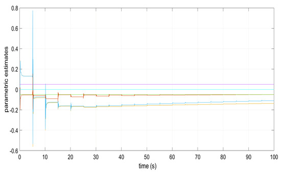
Figure 1.
Parametric estimates and in the absence of disturbances.
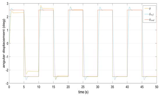
Figure 2.
Command signal tracking from the roll angle in the absence of perturbations.
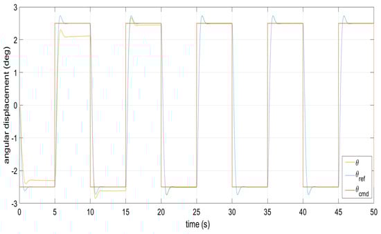
Figure 3.
Command signal tracking from the pitch angle in the absence of perturbations.
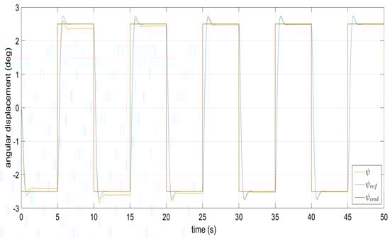
Figure 4.
Reference model following the yaw angle in the absence of perturbation.
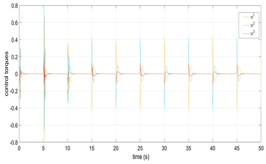
Figure 5.
Torque signals and in the absence of perturbations.
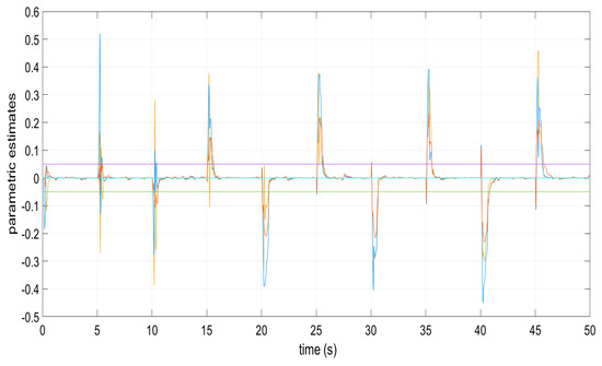
Figure 6.
Parametric estimates and in the appearance of perturbations.
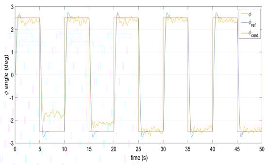
Figure 7.
Command signal tracking by the roll angle under perturbations.
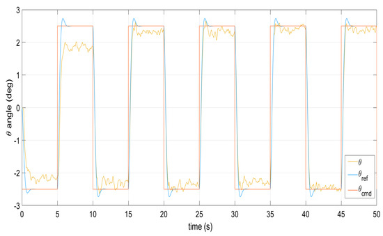
Figure 8.
Command signal tracking by the pitch angle under perturbations.
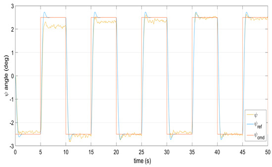
Figure 9.
Reference model following the yaw angle under external perturbations.
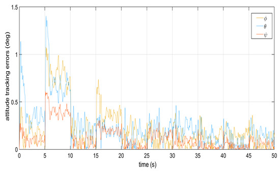
Figure 10.
Tracking errors from the dynamics of the attitude angles.
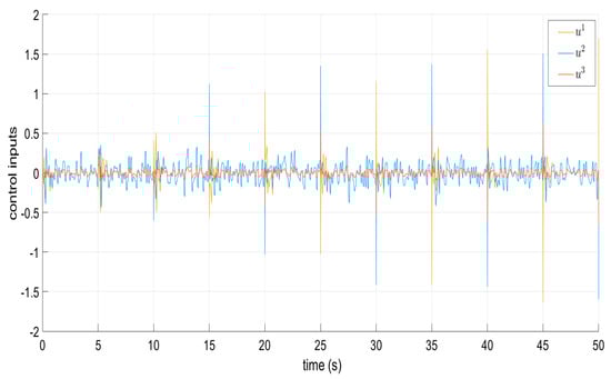
Figure 11.
Torque signals and when confronting perturbations.
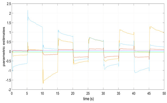
Figure 12.
Parametric estimates and under perturbations for .
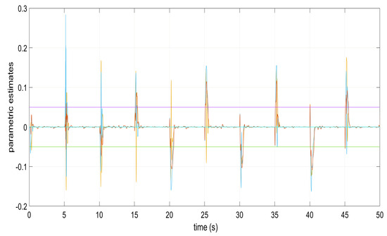
Figure 13.
Parametric estimates and in the appearance of perturbations for .
The norms and bounds of the error signal and parametric error from the decentralized MRAC with e-modification (38) are exhibited from Table 1, Table 2 and Table 3 for different values of . The best values for the error norm are highlighted in bold font. Therefore, it can be seen that the inequality (47) is satisfied. Thus, from Theorem 1, the robust model reference tracking problem under external unmatched perturbations for the MIMO system is solved.

Table 1.
Norms and bounds of the error signals and parametric error from the decentralized MRAC with e-modification for .
Table 2.
Norms and bounds from the error signals and parametric error from the decentralized MRAC with e-modification for .
Table 3.
Norms and bounds of the error signal and parametric error from the decentralized MRAC via e-modification for .
Figure 14, Figure 15, Figure 16, Figure 17, Figure 18 and Figure 19 exhibit the dynamics from the decentralized MRAC via smooth dead-zone modification (51) with and . It can be seen that the decentralized MRAC with smooth dead-zone modification (51) also faces, in a good measure, external perturbations when performing the reference tracking task. Table 4 shows the error signal norm whose values are not far from those for the decentralized MRAC with e-modification (38).
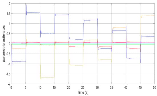
Figure 14.
Parametric estimates and in the appearance of perturbations.
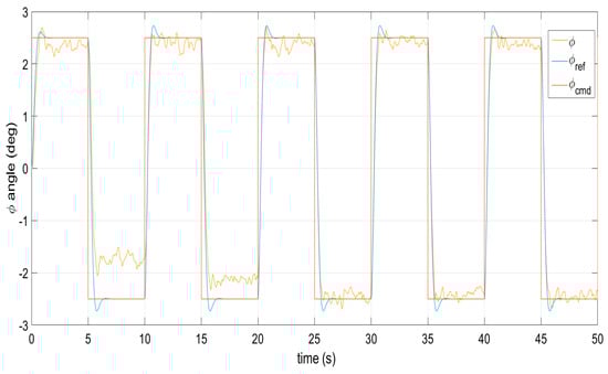
Figure 15.
Command signal tracking by the roll angle under perturbations.
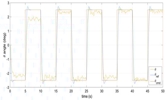
Figure 16.
Command signal tracking by the pitch angle under perturbations.
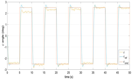
Figure 17.
Reference model following the yaw angle under external perturbations.
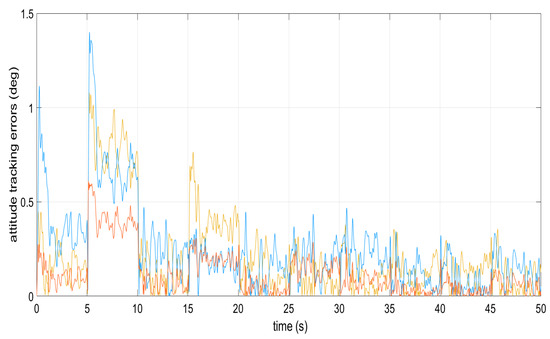
Figure 18.
Tracking errors from the dynamics of the attitude angles.
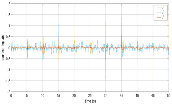
Figure 19.
Torque signals and when confronting perturbations.
Table 4.
Error signal norm from the decentralized MRAC via smooth dead-zone modification.
Table 5 shows the error signal norm from the decentralized MRAC with -modification, which was proposed in [28], for different values of . The best values are highlighted in bold font, which are those arising from using . Figures exhibiting the dynamics from this latter robust MRAC are not included here since its performance is very similar to that reported in [28].
Table 5.
Error signal norm from the decentralized MRAC with -modification.
5. Discussion
In the search for the design of a decentralized robust MRAC for the pose of a quadrotor UAV, the e-modification approach is investigated. It must be noticed that the development of this work was also conducted to the proposal of a decentralized robust MRAC via smooth dead-zone modification. For comparison purposes, their performance is contrasted with that from a decentralized robust MRAC previously reported in the literature but designed under the approach of -modification. From experimental simulation results, it can be seen that, through the decentralized MRAC via e-modification, it is possible to obtain the smallest values for the error signal norm between this latter approach and that via smooth dead-zone modification. Also, values from the error signal norm of the decentralized MRAC via smooth dead-zone modification show a good performance from this latter since they are very near those of the decentralized MRAC via e-modification. Moreover, it is interesting to note that the decentralized robust MRAC via -modification exhibits the smallest values of the error signal norm between pitch motion and yaw motion subsystems. Likewise, from this work, it can be seen that the decentralized MRACs for the pose of a quadrotor UAV are robust under the effect of external perturbations since the parametric estimates do not drift to infinity. Additionally, the purpose of most control system designs is to regulate small motions rather than to control absolute position, as is the case with spacecraft attitude dynamics control, where the disturbance (gravitational) torques are of a very low order. Thus, it is worthwhile to note that our proposal could be exploited in the satellite attitude control.
6. Conclusions
It can be seen that, from simulation results, the parametric estimates from the adaptive laws converge to their ideal values in the absence of perturbations for the decentralized MRAC via e-modification. In contrast, in the presence of external perturbations, the parametric estimates tend to the origin, i.e., the parametric estimates from the adaptive laws do not drift to infinity when the decentralized MRAC via e-modification for the pose of the quadrotor UAV has to confront external perturbations. From the above, it can be concluded that the decentralized MRAC via e-modification is robust. Also, the parametric estimation errors do not converge to the origin when the decentralized MRAC with e-modification is under the influence of external perturbations. Moreover, the decentralized MRAC via smooth dead-zone modification is a good option when confronting perturbations. Additionally, it must be noted that the quadrotor UAV arrives at the reference for the altitude in both scenarios. Likewise, our proposal allows us to combine the decentralized robust MRACs, like those from the pitch motion and yaw motion from the -modification, with that for the roll motion from the e-modification, in the achievement of the best performance to the model reference tracking task. Furthermore, the yaw motion subsystem, as it has been shown through experience, demands the minimum control effort in comparison with those from the remaining subsystems.
Author Contributions
Conceptualization, F.J.; investigation, F.J. and E.J.O.-V.; methodology, F.J.; formal analysis, F.J. and E.J.O.-V.; validation, F.J. and E.J.O.-V.; software, F.J.; data curation, F.J. and E.J.O.-V.; visualization, F.J. and E.J.O.-V.; writing–original draft preparation, F.J.; writing–review and editing, F.J.; supervision, F.J.; funding acquisition, F.J.; resources, F.J.; project administration, F.J. All authors have read and agreed to the published version of the manuscript.
Funding
This research was funded by Tecnológico Nacional de México (TecNM) under project 23003.25-P and, partially, under a grant 47338 from the EDD 2024 program. This work was developed under the framework of the Red Internacional de Control y Cómputo Aplicados.
Data Availability Statement
The original contributions presented in the study are included in the article. Further inquiries can be directed to the corresponding author.
Conflicts of Interest
The authors declare no conflicts of interest.
Abbreviations
The following abbreviations are used in this manuscript:
| AMSSC | Adaptive multiple-surface sliding controller |
| DOF | Degree-of-freedom |
| HIL | Hardware-in-the-loop |
| LQR | Linear quadratic regulator |
| MIMO | Multiple-input multiple-output |
| MRAC | Model reference adaptive control |
| PID | Proportional–integral–derivative |
| UAV | Unmanned aerial vehicle |
| UUB | Uniform ultimate boundedness |
References
- Slotine, J.J.E.; Li, W. Applied Nonlinear Control; Prentice Hall: Englewood Cliffs, NJ, USA, 1991. [Google Scholar]
- Ioannou, P.A.; Sun, J. Robust Adaptive Control; Prentice Hall PTR: Upper Saddle River, NJ, USA, 1995. [Google Scholar]
- Lavretsky, E.; Wise, K.A. Robust and Adaptive Control with Aerospace Applications; Springer: London, UK, 2013. [Google Scholar]
- Peterson, B.B.; Narendra, K.S. Bounded error adaptive control. IEEE Trans. Automat. Contr. 1982, 27, 1161–1168. [Google Scholar] [CrossRef]
- Ioannou, P.A.; Kokotovic, P.V. Adaptive Systems with Reduced Models; Springer: New York, NY, USA, 1983. [Google Scholar]
- Ioannou, P.; Fidan, B. Adaptive Control Tutorial; SIAM: Philadelphia, PA, USA, 2006. [Google Scholar]
- Rohrs, C.E.; Valavani, L.S.; Athans, M.; Stein, G. Robustness of continuous time adaptive control algorithm in the presence of unmodeled dynamics. IEEE Trans. Autom. Control 1985, 30, 881–889. [Google Scholar] [CrossRef]
- Narendra, K.S.; Annaswamy, A.M. A new adaptive law for robust adaptive control without persistency of excitation. IEEE Trans. Autom. Control 1987, 32, 134–145. [Google Scholar] [CrossRef]
- Narendra, K.S.; Annaswamy, A.M. Stable Adaptive Systems; Prentice Hall: Englewood Cliffs, NJ, USA, 1989. [Google Scholar]
- Slotine, J.J.E.; Coetsee, J.A. Adaptive sliding controller synthesis for nonlinear systems. Int. J. Control 1986, 43, 1639–1651. [Google Scholar] [CrossRef]
- Farrell, J.A.; Polycarpou, M.M. Adaptive Approximation Based Control; Wiley: Hoboken, NJ, USA, 2006. [Google Scholar]
- Bodson, M. Adaptive Estimation and Control; Independently Published: Coppell, TX, USA, 2020. [Google Scholar]
- Kitsios, I.; Dobrokhodov, V.; Kaminer, I.; Jones, K.D.; Xargay, E.; Hovakimyan, N.; Cao, C.; Lizarraga, M.I.; Gregory, I.M.; Nguyen, N.T.; et al. Experimental Validation of a Metrics Driven L1 Adaptive Control in the Presence of General Unmodeled Dynamics. In Proceedings of the AIAA Guidance, Navigation, and Control Conference, Chicago, IL, USA, 10–13 August 2009. [Google Scholar]
- Huang, A.C.; Chen, Y.F.; Kai, C.Y. Adaptive Control of Underactuated Mechanical Systems; World Scientific Publishing Co. Pte. Ltd.: Singapore, 2015; pp. 45–53. [Google Scholar]
- Yucelen, T.; Calise, A.J. Derivative-Free Adaptive Control; American Institute of Aeronautics and Astronautics, Inc.: Reston, VA, USA, 2023. [Google Scholar]
- Martini, S.; Mennea, S.M.; Mihalkov, M.; Rizzo, A.; Valavanis, K.; Sorniotti, A.; Montanaro, U. Design and HIL Testing of Enhanced MRAC Algorithms to Improve Tracking Performance of LQ-strategies for Quadrotor UAVs. In Proceedings of the 2024 IEEE 20th International Conference on Automation Science and Engineering (CASE), Bari, Italy, 28 August–1 September 2024. [Google Scholar]
- Kumar, G.M.; Gramuglia, M.; L’Afflitto, A. Robust Hybrid Model Reference Adaptive Control and Output-Feedback Linearization with Applications to Quadcopter UAVs. In Adaptive Control Theory and Applications; Ioannou, P., Ed.; IntechOpen Limited: London, UK, 2024; pp. 49–72. [Google Scholar]
- Etkin, B.; Reid, L.D. Dynamics of Flight, Stability and Control, 3rd ed.; John Wiley & Sons: New York, NY, USA, 1996. [Google Scholar]
- Nijmeijer, H.; van der Schaft, A. Nonlinear Dynamical Control Systems; Springer: New York, NY, USA, 1990. [Google Scholar]
- Friedland, B. Control System Design: An Introduction to State-Space Methods; Dover Publications, Inc.: Mineola, NY, USA, 2005. [Google Scholar]
- Bouabdallah, S.; Murrieri, P.; Siegwart, R. Design and Control of an Indoor Micro Quadrotor. In Proceedings of the IEEE International Conference on Robotics and Automation, New Orleans, LA, USA, 26 April–1 May 2004. [Google Scholar]
- Stevens, B.L.; Lewis, F.L. Aircraft Control and Simulation, 2nd ed.; John Wiley & Sons: Hoboken, NJ, USA, 2003. [Google Scholar]
- Šiljak, D.D. Decentralized Control of Complex Systems; Dover Publications, Inc.: Mineola, NY, USA, 2012. [Google Scholar]
- User Manual QBall 2 for QUARC; Quanser Inc.: Markham, ON, Canada, 2014.
- Jurado, F.; Lopez, S.; Dzul, A.; Rodríguez-Cortés, H. Decentralized control of the quadrotor’s 6-DOF. In Proceedings of the 2017 International Conference on Mechatronics, Electronics and Automotive Engineering (ICMEAE), Cuernavaca, Mexico, 21–24 November 2017. [Google Scholar]
- Jurado, F.; Hernández, R. Decentralized MRAC with integral action for attitude control of a quadrotor UAV. In Proceedings of the 2018 IEEE International Autumn Meeting on Power, Electronics and Computing (ROPEC), Ixtapa, Mexico, 14–16 November 2018. [Google Scholar]
- Åström, K.; Hagglund, T. PID Controllers: Theory, Design, and Tuning, 2nd ed; ISA—The Instrumentation, Systems and Automation Society: Durham, NC, USA, 1995. [Google Scholar]
- Jurado, F. Decentralized Robust Direct MRAC for the Attitude of a Quadrotor UAV. In Adaptive Control Theory and Applications; Ioannou, P., Ed.; IntechOpen Limited: London, UK, 2024; pp. 73–88. [Google Scholar]


Disclaimer/Publisher’s Note: The statements, opinions and data contained in all publications are solely those of the individual author(s) and contributor(s) and not of MDPI and/or the editor(s). MDPI and/or the editor(s) disclaim responsibility for any injury to people or property resulting from any ideas, methods, instructions or products referred to in the content. |
© 2025 by the authors. Licensee MDPI, Basel, Switzerland. This article is an open access article distributed under the terms and conditions of the Creative Commons Attribution (CC BY) license (https://creativecommons.org/licenses/by/4.0/).