Abstract
In view of the prominent problem that nonlinear vibration of a belt conveyor can easily occur during the vertical grain-conveyance process due to the coupling effect of airflow clamping and traction of the conveyor belt, which seriously affects the efficiency and stability of conveying materials by the belt conveyor, a method of solving the vibration analysis of the vertical lifting section of the bulk grain belt unloader by using nonlinear vibration is proposed. Firstly, based on the laminated plate theory, the vertical lifting belt and the grain material clamped by the belt are laminated. The nonlinear vibration differential equation of the vertical lifting section of the bulk grain-carrying ship unloader is established by elastic–plastic mechanics, and solved by perturbation theory and Galerkin discrete analysis. The vibration response curve and structural natural frequency of the vertical lifting section of the bulk grain-carrying machine are obtained by numerical solution, and the influence of the volume content of the clamped material on the vibration response and structural natural frequency of the lifting section is analyzed. This study provides theoretical support for the design of pressure-supply parameters, overall structure and operation parameters of the subsequent entrainment ship unloader, promotes the rapid development of the entrainment ship unloader, provides theoretical support for the design, manufacture, later operation, and maintenance of the entrainment ship unloader, and thus provides equipment and technical support for building an efficient and intelligent port.
1. Introduction
At present, the vertical transportation of bulk materials such as grain in a project mainly relies on mechanical, pneumatic, and mechanical and pneumatic combinations. The vertical conveyance of a bulk grain entrainment ship unloader mainly relies on pneumatic force to clamp grain and other bulk materials through two synchronous belts, and uses the balance between the friction between the belt and the material (material and material) and the gravity of the material to ensure the relative stability of the material and the timing belt, and the high-speed movement of the synchronous belt drives the material to achieve vertical lifting movement. The deviation of the synchronous belt movement, the shaking of the belt itself during the movement of the synchronous belt, and the stability of the clamping force provided by the external air pressure are important factors and guarantee conditions affecting the vertical lifting of the blessing material. During the material lifting process, the rubber belt and grain are affected by the speed difference between the timing belt, the shaking of the belt, the instability of the clamping force, and the unstable tensile traction load of the synchronous belt. It leads to the unstable action of belt and grain, resulting in the return of materials in the vertical lifting process of bulk materials, which seriously affects the overall lifting efficiency and overall stability of equipment.
There are relatively few studies on unstable vibration phenomena in the vertical lifting process of the Entironment ship unloader, and most researchers focus on the vibration and reliability of the belt structure. Based on the Galerkin method, Zhang Ruijun [1] analyzed the frequency response of the transverse vibration synchronous belt and obtained the relationship between the band speed and the natural frequency of the transverse vibration. Xing Yading [2] applied the Hamiltonian principle to propose an adaptive robust boundary controller to suppress longitudinal vibration of wire rope and effectively suppress longitudinal vibration of lifting rope and container. Piotr Bortnowsk [3] studied the influence of belt tension on belt vibration frequency in a conveyor. Based on experimental and theoretical analysis, Witold Kawalec [4] obtained the distribution law of transverse vibration frequency of a conveyor belt along its length direction. Based on the above research, this paper proposes that the unstable vibration during vertical lifting of the Entironment ship unloader belongs to nonlinear flutter [5]. M. Bilasse [6] proposed a numerical analysis method for linear and nonlinear vibration of viscoelastic sandwich plates. Marco Amabili [7] used the arc-length-extension collocation method to identify a solution to discretized nonlinear vibration. Hui Li [8] investigated the vibration mechanism of multi-viscoelastic laminated-fiber metal laminates at different external excitation levels. Ola Ragb [9] proved that discrete singular convolution differential quadrature methods are an effective way of analyzing the nonlinear vibration of multilayer composite plates with elastic support. In order to solve the nonlinear flutter during the vertical lifting of the Entironment ship unloader, the vertical lifting section of the Entironment ship unloader was simplified into a three-layer composite plate structure [10], and the structure was analyzed. Ashes Maji [11] analyzed the research status of single-layer laminate and laminate theory. Dinghe Li [12] provided a systematic review and current situation analysis of lightweight composite structures and their applications. Nguyen Chi Tho [13] used the third-order shear-deformation theory combined with phase field theory to simulate the free vibration response and static bending of laminated composite plates with only core layer fractures, and found the that crack length changes influenced the natural frequency and maximum deflection of plate structure. Hai van, Nguyen Thi [14] used Hermite and Lagrange functions and a new 3D plate to simulate the buckling and free vibration problems of non-uniform thickness bidirectional functionality gradient intercalated porous plates with variable elastic foundation. Atteshamuddin S. Sayyad [15] obtained the analytical solution of Navier type through a comparative analysis of laminated composite plates and sandwich plates.
The key to studying nonlinear flutter of laminated plates is to establish and solve the vibration differential equation of the structure. Katica S. Hedrih [16,17] derived and solved analytically coupled partial differential equations of the transversal vibrations of an axially moving sandwich double-belt system. A numerical experiment and visualization were carried out. Bernoulli’s method of particular integrals and Lagrange’s method of the variations of the constants were used to solve the partial differential equations. Based on the above methods, this paper proposes to use perturbation theory and Glerkin discrete analysis to solve this vibration differential equation. Di Rocco et al. [18] show that the simplest results of time-independent perturbation theory can be used for the systematization of many experimental data from atomic physics. Francisco M. Fernández [19] analyzed earlier applications of perturbation theory by applying the inner-product method to anharmonic oscillators. Qingbo Wang et al. [20] formulated three governing differential equations of vibration of a tower with inhomogeneous material and a variable cross section based on d’Alembert’s principle and Euler–Bernoulli beam theory, and revealed the influence of the foundation stiffness, wall thickness, eccentricity, and the ratio of the inner diameter of the top and bottom cross section of a tower on the vibration characteristics of that tower. Alvaro H. S. Salas [21] used the Galerkin method to solve nonlinear second-order partial differential equations and compared them with Runge Kutta numerical solutions. Ji Wang et al. [22] extended the popular Galerkin method. And this extended Galerkin method can also be utilized for the analysis of free and forced nonlinear vibrations of structures with efficient and accurate advantages in solving equations.
In summary, this paper mainly studies the nonlinear vibration of the vertical lifting section of the bulk grain carrier ship unloader. Then, a nonlinear vibration model of the whole vertical segment of the lifting process is constructed based on the laminated theory. Finally, the vibration model is solved by perturbation theory and Galerkin discrete analysis. A test platform for a small-sized entrainment ship unloader was built in the laboratory. Many experiments have shown that the above results have a high degree of fit with the experimental results. The research results will provide theoretical support for the design, manufacture, later operation, and maintenance of the entrainment ship unloader and the early warning of equipment safety.
2. Modeling the Vibration Differential Equation of the Vertical Lifting Section of the Entrainment Ship Unloader
2.1. Entrainment Ship Unloader Vertical Lifting Principle
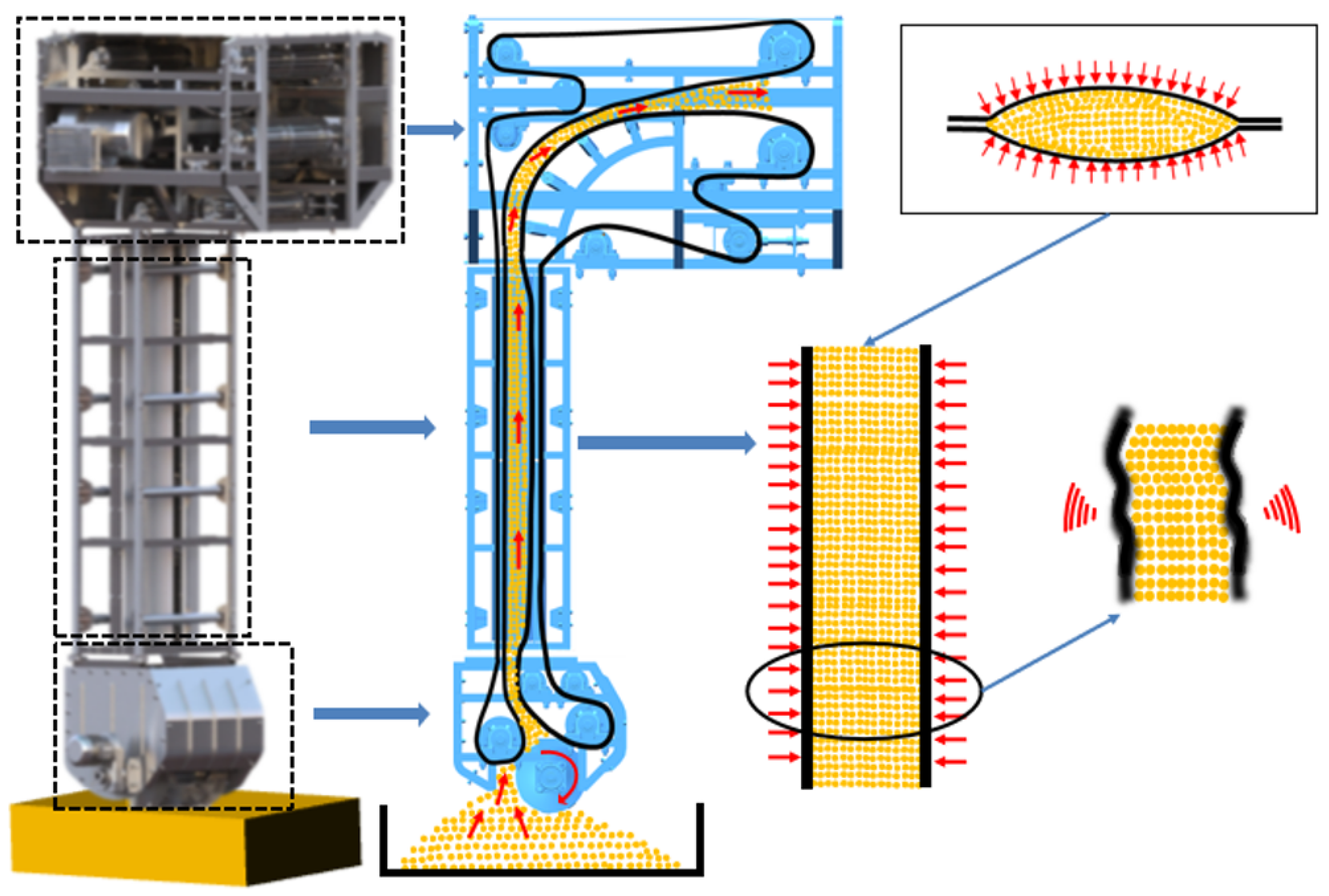
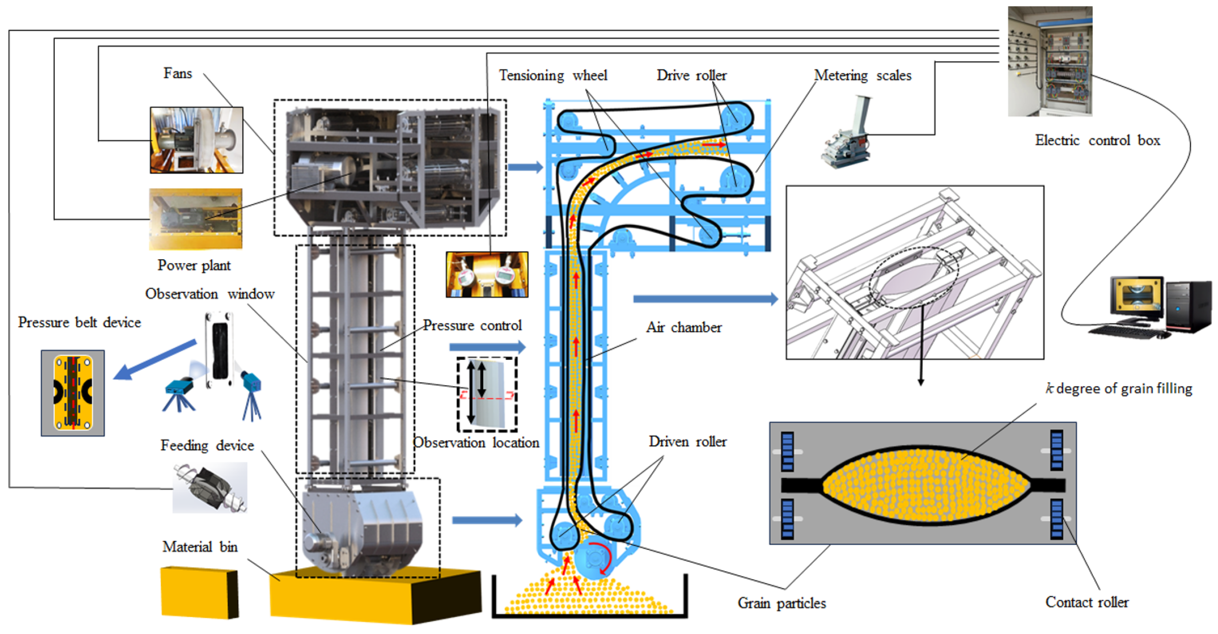
An entrainment ship unloader mainly comprises a feeding device, vertical lifting device, and discharge device. The vertical lifting device is shown in Figure 1. The structure is composed of a synchronous running bearing conveyor belt and a covered conveyor belt; between the two forms, there is a material-conveying space, and the air chamber wraps the material conveyor belt. The air chamber is divided into two curved cavities, and the curved cavity includes the inner arc surface shell and the outer zigzag shell connected by the seal, and the inner arc surface shell and the outer zigzag shell form an air chamber. There are multiple gas outlets on the inner arc shell, and the gas in the gas supply chamber applies gas pressure to the bearing conveyor belt and the covering conveyor belt. The curved cavities are set relative to each other, the two inner arc surface shells are interlocked, and the bearing conveyor belt and the cover conveyor belt are sandwiched therein. The belt edge of the bearing conveyor belt and the covering conveyor belt are connected with the edges of the two curved cavities through the edge banding device.

Figure 1.
Schematic diagram of the vertical lifting section of the entrainment ship unloader.
2.2. Vertical Lifting Process Rubber Belt, Material Three-Layer Structure
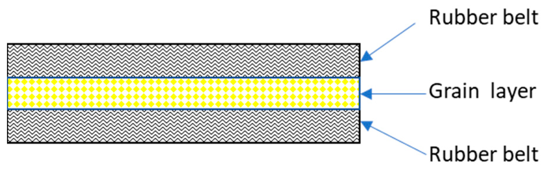
As shown in Figure 1, the covering belt and the bearing belt compacted the bulk material under the action of suspension pressure, and then under the action of the driving force and the belt clamping, the vertical lifting of the bulk material in the synchronous belt clamping action was realized. Due to the action of external force in the lifting process, the structure of the material remains relatively stable under the clamping action of the rubber belt, and the relative sliding and slippage between the material and the rubber belt does not occur; the material tends to be isotropic and ideal inside. Based on the ideal hypothesis, the vibration differential equation of the vertical lifting section structure of the rubber belt was established based on the three-layer composite structure, in order to obtain the vibration characteristics and related influencing factors affecting the structure of the bulk material clamping and lifting process by solving the vibration differential equation [12]. Finally, the entrainment unloader design was given guidance. The three-layer structure of the rubber belt and material in the vertical lifting process is shown in Figure 2.

Figure 2.
Laminated structure of rubber belt material.
Based on the layering theory, the composite elastic modulus and composite density of the laminated structure are calculated as follows:
where E1 is the elastic modulus of the rubber belt, ρ1 is the density, E2 is the elastic modulus of grain material structure under clamping, ρ2 is the density of grain material structure under clamping, and k is degree of grain filling in the cross section.
2.3. Vibration Differential Equations for Vertical Lifting Processes
Figure 3 shows the dynamic model of the structure, where L is the span length of the laminated structure, c is the axial motion speed of the structure, u and v are the displacements of any point on the band in the X and Y directions, respectively, and F is the tensile force borne by the structure. The overall structure modeling process makes the following simple assumptions [16,17]:
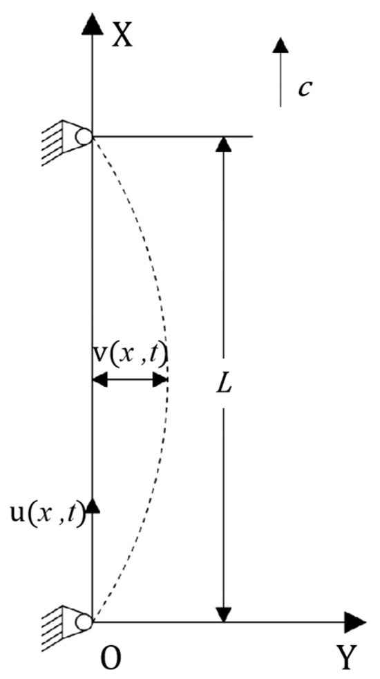
Figure 3.
Structural dynamics models.
- (1)
- The composite structure is composed of uniform materials and the stress is within the elastic limit range;
- (2)
- The movement speed c of the structure in the axial direction is constant and uniform;
- (3)
- Only consider the lateral displacement of the structure in the Y direction;
- (4)
- The bending stiffness of the structure is negligible;
- (5)
- The structure is in a uniform initial tensile state.
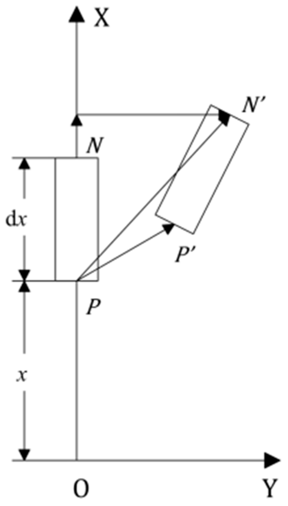
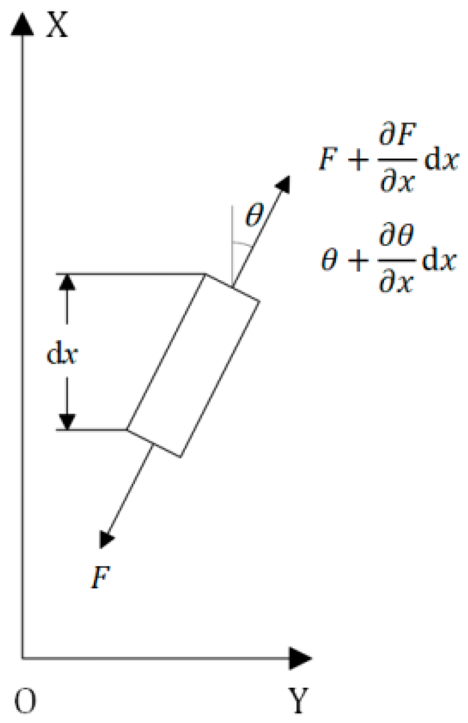
In order to establish the vibration differential equation of the structure, a microelement segment of the structure was taken for analysis, and the microelement segment structure is shown in Figure 4. The microelement segment is located at x from the origin O; P and N are the two endpoints of the microsegment; and P′ and N′ are the two endpoints after the microsegment deformation.

Figure 4.
Structural microelement segment model.
Then, the displacement of point P is calculated as follows:
The displacement at point N is calculated as follows:
The length of the microelement segment after force deformation is calculated as follows:
The strain ε of the structure at this point can be expressed as
We performed a Taylor expansion of Equation (5) and retained it for the quadratic term yields:
Strain in the X direction was ignored and only the lateral vibration of the structure in the Y direction was taken into account, as follows:
The stress–strain relationship of the structure is calculated as follows:
Under the action of the driving force of layers and structures, the structure is subjected to a tension that changes over time, which is calculated as follows:
where A is the cross-sectional area of the structure, and F0 is the initial tension of the laminated structure.
Force analysis of structural microelement segments is shown in Figure 5.
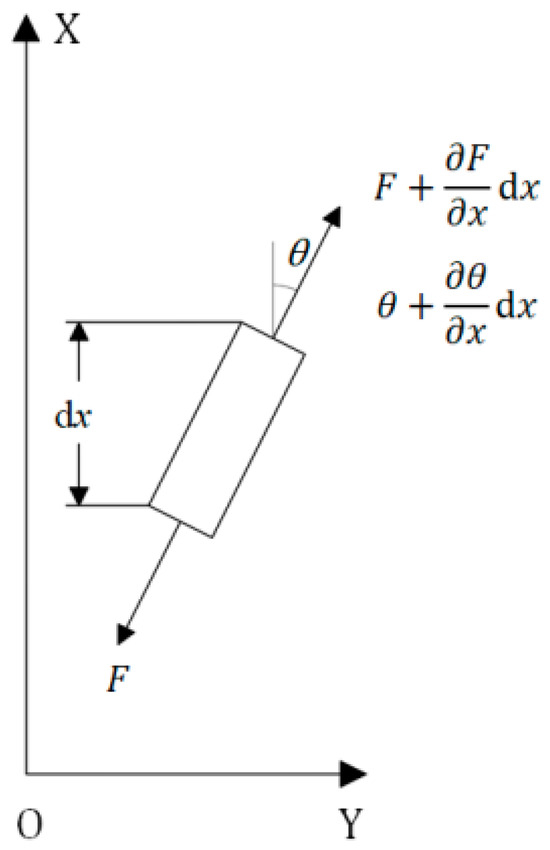
Figure 5.
The force of the structural microelement segment.
The dynamics of a structure at a certain moment is calculated using Newton’s laws of motion, as follows:
where is the deflection angle along the X-axis. The lateral acceleration for composite structures in Equation (10) is calculated as follows:
There is as follows, for small deformation cases of the structure.
Without considering the damping characteristics of the structure, Equation (12) is obtained as follows:
In order to solve Equation (13), it is normalized as follows:
obtain
make in Equation (14). Equation (14) is replaced as follows:
3. Solving Vibration Differential Equations Based on Perturbation Method
Where a small dimensionless parameter was introduced, Equation (15) is transformed using multi-scale perturbation theory [1] as follows:
where mass, gyroscope, and linear stiffness operators are introduced. By substituting it into Equation (16), the dynamic equation of the composite structure is obtained as follows:
Let the uniformly asymptotic solution of Equation (17) be
where , and the time derivative represented by T0 and T1 becomes
Substituting Equation (18) into Equation (17) yields
Substituting Equations (19) and (20) into Equation (21) yields
Make both sides of the equation , the coefficients are equal, and the order of is obtained as follows:
is obtained as follows:
where , the boundary conditions for the simplified model are obtained as follows:
The general solution of Equation (23) is expressed in the complex form of separated variables as follows:
where is the nth order modal function of the system; is the nth order vibration amplitude of the system; is the nth natural frequency; aa is the complex conjugate of the previous term.
The natural frequency of the nth order and modal function are obtained as follows:
3.1. Solution Based on Galerkin Discrete Analysis
The dynamic Equation (12) of the structure contains the variables of time and space coordinates, and it is a differential equation that is not convenient for analysis and calculation. Therefore, the equation was discretized and decoupled using the Galerkin method [6], which obtained a general ordinary differential equation that was easy to solve and calculate. According to Equation (27), the solution of the vibration equation is obtained by using the time function and spatial functions represents as follows:
The spatial function is the main mode of vibration of the lateral motion, where r = 1, 2, 3, … n in Equation (28), is expressed as follows:
Since the vibration of the vertical material-conveying system mainly affects the structural stability with low-frequency vibration, the first two modes of the system are mainly used. Equation (29) is substituted into Equation (14), the Galerkin of the first two orders is truncated, and the orthogonality of the modal function is used to multiply on both sides of the equation. The partial differential Equation (14) is converted into a second-order nonlinear ordinary differential equation after integral operation on the interval [0, 1] as follows:
Equations (30) and (31) are the second-order nonlinear ordinary differential equation of the transverse vibration of the vertical material-conveying system. The first- and second-order vibration responses of the structure are obtained based on differential equations.
Based on the experimental method presented in [23], the elastic modulus of common varieties of soybean, wheat, and corn was measured in this study, and the average elastic modulus values obtained are shown in Table 1.

Table 1.
Parameters of laminated structure.
Obtain the elastic modulus and density of different grains as laminated structures from Table 1 and Equation (1), and substitute them into Equation (32) to obtain different parameters as shown in Table 2, Table 3 and Table 4.
Table 2.
Parameters of the laminated structure of soybean particles and rubber conveyor belts.
Table 3.
Parameters of the laminated structure of wheat particles and rubber conveyor belts.
Table 4.
Parameters of the laminated structure of corn granules and rubber conveyor belt.
Take the gravity of the laminated structure for F0, then
where is the Poisson’s ratio [24].
3.2. Discussion of Results
The displacement responses of structure after normalization were calculated by using Equations (30) and (31), and they are shown in Table 2, Table 3 and Table 4, where soybean, wheat, and corn are regarded as vertical lifting material. Then, the structural response q1 and q2 curves were obtained, which was the relationship curve between the displacement responses of structure after normalization and different filling degrees as shown in Figure 6, Figure 7 and Figure 8.

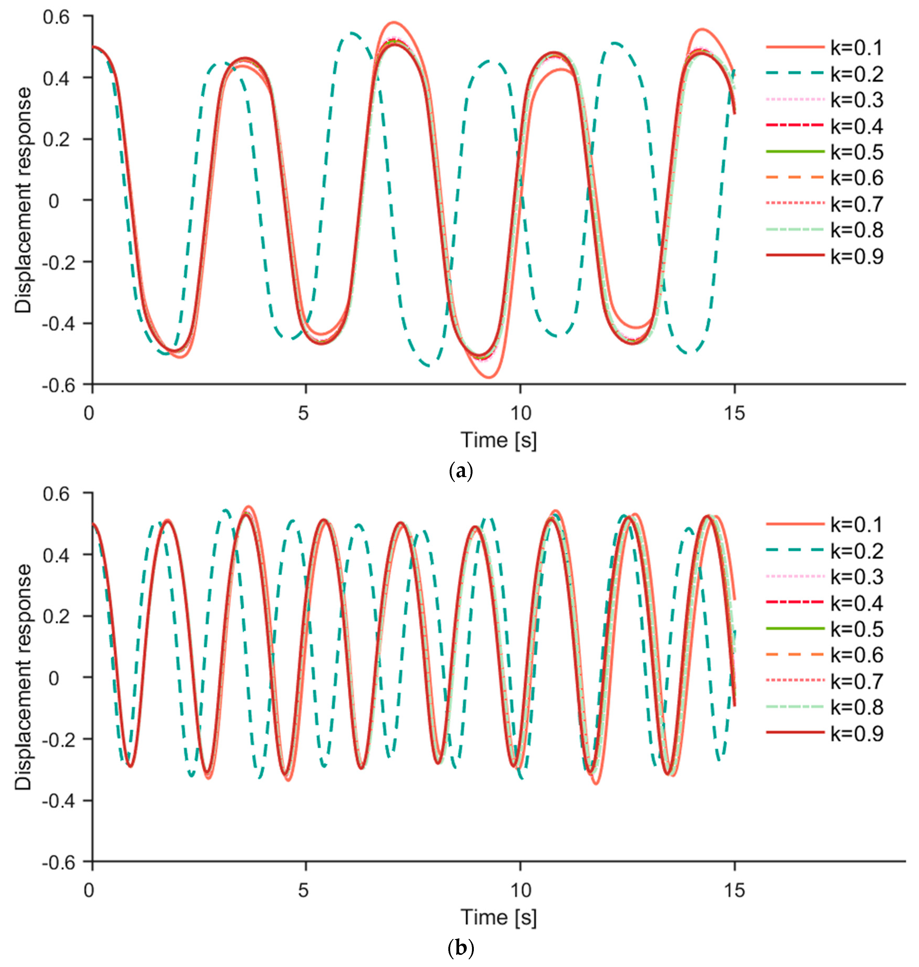
Figure 6.
(a) The first−order response q1 of different filling degrees k (soybean as a sample). (b) The second−order response q2 of different filling degrees k (soybean as a sample).
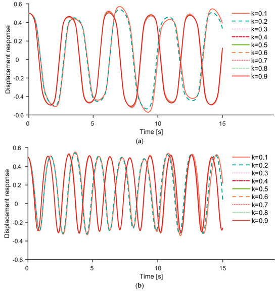
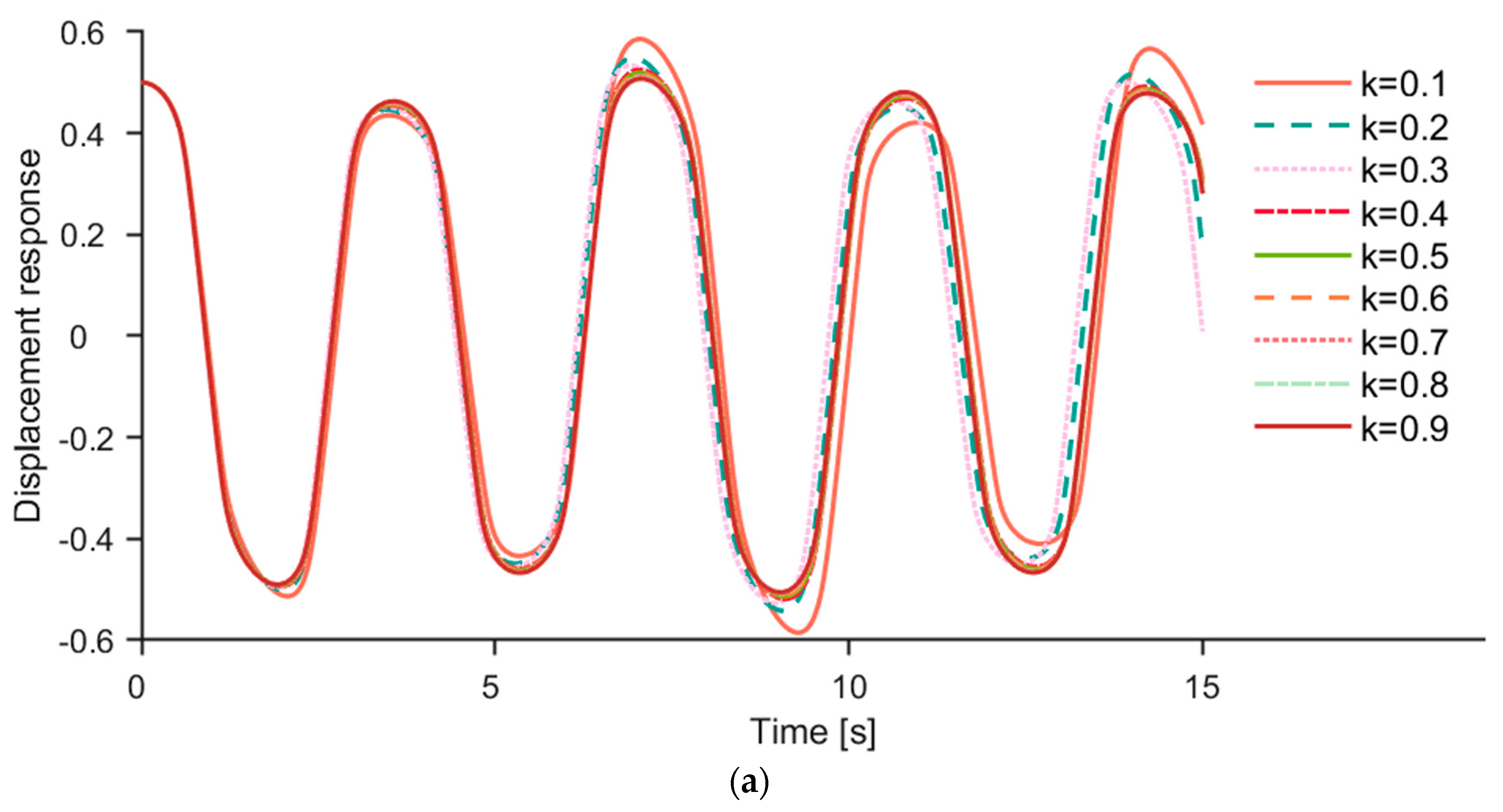
Figure 7.
(a) The first−order response q1 of different filling degrees k (wheat as a sample). (b) The second−order response q2 of different filling degrees k (wheat as a sample).
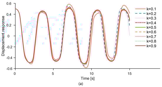
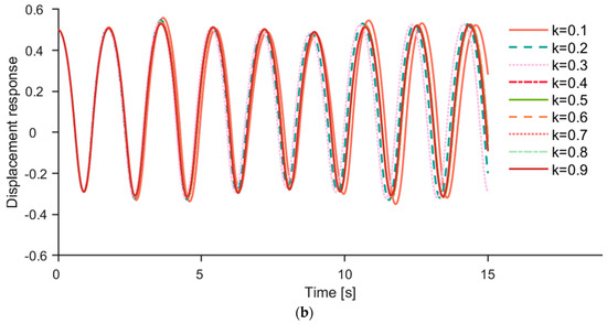
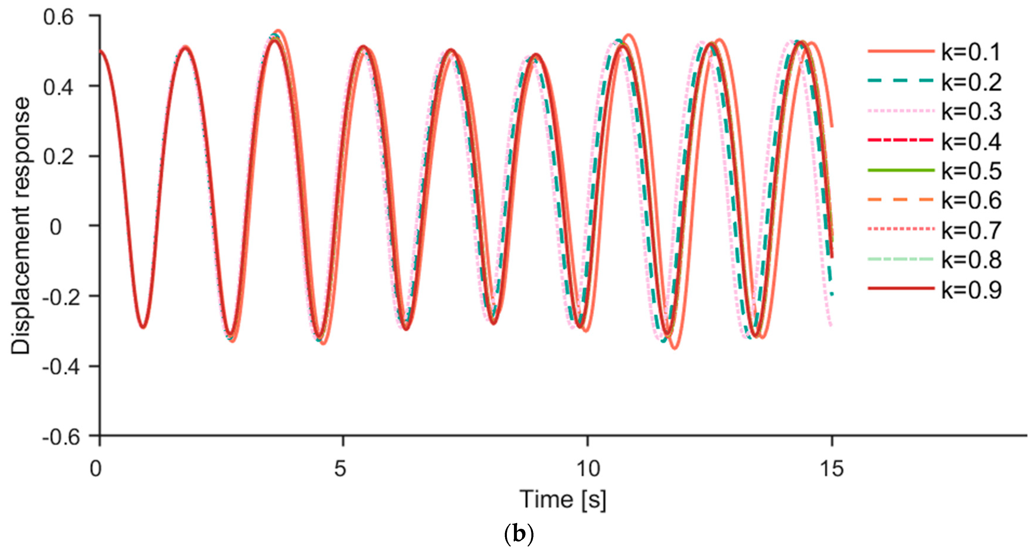
Figure 8.
(a) The first−order response q1 of different filling degrees k (corn as a sample). (b) The second−order response q2 of different filling degrees k (corn as a sample).
Figure 6a,b show the first-order and second-order responses of different filling degrees k, respectively, where the conveyed material was soybean particles. And the fluctuation period changed significantly when the k value increased from 0.1 to 0.2. The frequency of q1 and q2 was calculated, which showed the frequency of q1 increases from 0.2823 Hz to 0.3283 Hz and the frequency of q2 increases from 0.5501 to 0.6462 Hz, following the increase in k value from 0.1 to 0.2. In addition, the wave patterns of q1 and q2 were consistent with different filling degrees, and the fluctuation period of q1 was approximately twice that of q2.
Figure 7a,b show the first-order and second-order responses of different filling degrees k, respectively, where the conveyed material was wheat particles. And the fluctuation period change significantly when the k value increased from 0.2 to 0.3. The frequency of q1 and q2 was calculated, which showed that the frequency of q1 increases from 0.2815 Hz to 0.3205 Hz and the frequency of q1 increases from 0.5567 to 0.6349 Hz, following the increase in the k value from 0.2 to 0.3. In addition, the wave patterns of q1 and q2 were consistent with different filling degrees, and the fluctuation period of q1 was approximately twice that of q2.
Figure 8a,b show the first-order and second-order responses of different filling degrees k, where the conveyed material was corn particles. And the fluctuation period changed insignificantly when the k value increased from 0.1 to 0.3. The frequency of q1 and q2 was calculated, which showed that the frequency of q1 increases from 0.2804 to 0.2880 Hz and the frequency of q2 increases from 0.5487 to 0.5653 Hz, following the increase in the k value from 0.1 to 0.3. The vibration frequencies of q1 and q2 varied less at different filling degrees. In addition, the wave patterns of q1 and q2 were consistent with different filling degrees, and the fluctuation period of q1 was approximately twice that of q2.
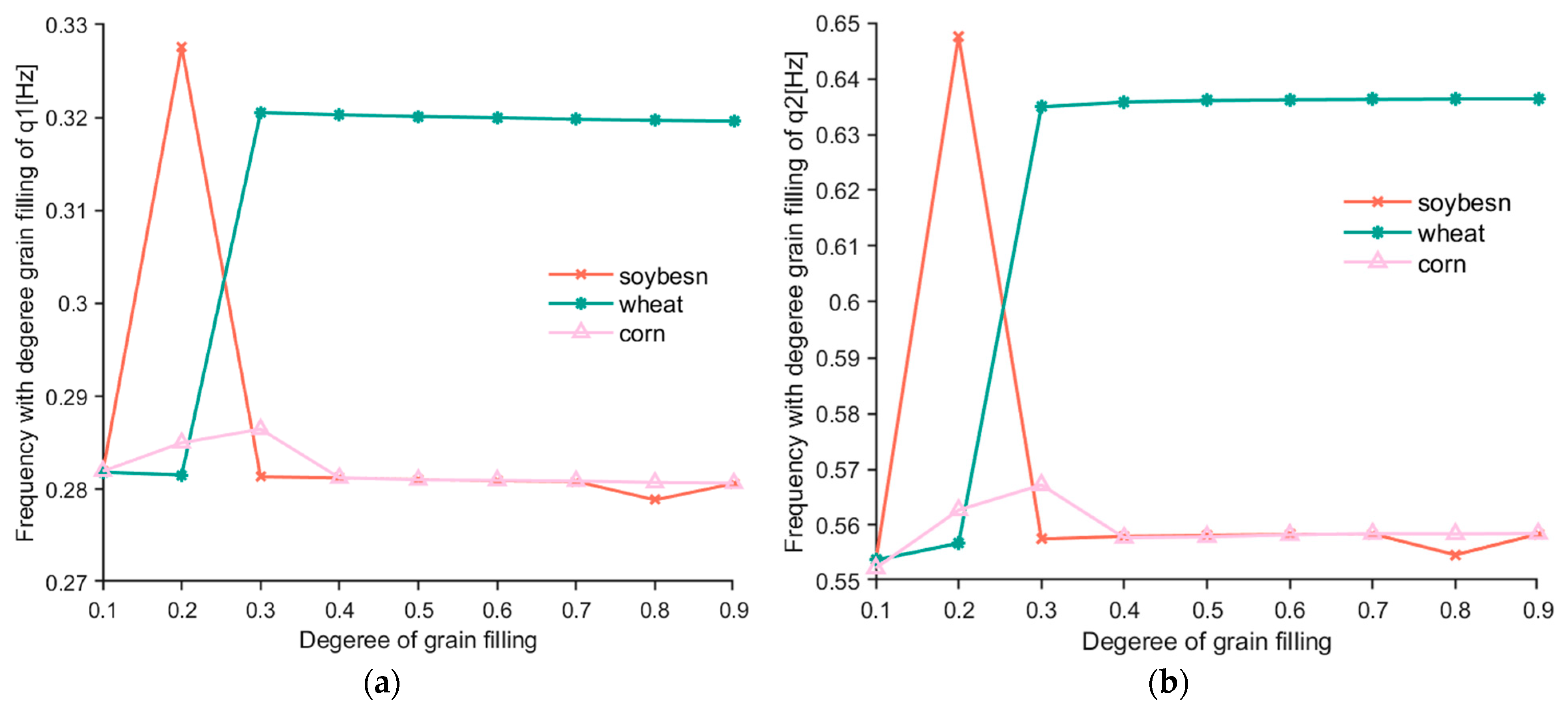
The correspondence curves of the first- and second-order response frequencies of the system obtained after normalization treatment and the filling degree of different materials are shown in Figure 9. Figure 9a shows the relationship between the frequency of q1 and the filling degree of different materials. Figure 9b shows the relationship between the frequency of q2 and the filling degree of different materials. By comparing Figure 9a,b, it was found that the first- and second-order response frequency curves under a different material filling degree k were completely consistent. The difference is that the second-order response frequency was twice that of the first-order response frequency.
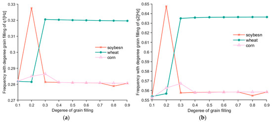
Figure 9.
Relationship: (a) The frequencies of q1 and k of three materials; (b) The frequencies of q2 and k of three materials.
Through the analysis of three different grain materials, we found the following: when the filling degree is between 0.1 and 0.3, the frequency fluctuates greatly; when the filling degree is greater than 0.3, the frequency tends to be stable. It can be seen that the lower the filling degree, the more unstable the frequency, and the frequency tends to be stable as the filling degree increases. In addition, when soybean and corn were used as lifting materials, the frequency of structural response first increases, then decreases with the change of material filling degree, and finally tends to be stable. When wheat particles are used as lifting materials, the structural response frequency continues to increase with the change of filling degree, and then becomes stable.
When soybean and corn are used as lifting materials, the stable value of their structural response frequency increases with the increase in filling degree, which is also lower than the stable value of structural response frequency when wheat is used as lifting material.
In this study, the first- and second-order response frequencies of the structure were obtained under different filling degrees of three kinds of lifting materials. It can be used as a reference to guide the frequency design of the moving speed of the synchronous belt and the pressure-supply device of the clamping force during the operation of the clamping and lifting structure, which avoids the working speed of the engineered synchronous belt and the pressure-supply frequency of the pressure-supply device being consistent with or close to the structural frequency, avoids the resonance and strong flutter of the structure during operation, and avoids the instability of the equipment’s clamping materials.
In addition, the difference between the three materials has a significant impact on the response frequency of each order of the laminated structure. Therefore, the design of the equipment’s future operating parameters needs to be combined with the material properties, which will avoid the instability caused by the consistent response frequency of each order of the laminated structure, so as to ensure the intelligence and efficiency of the design equipment.
4. Verification Experiment
A preliminary verification experiment was designed based on the above calculation results. As shown in Figure 9, it was found that when soybean was used as the filling material, the variation of structural response frequency fluctuated the most, especially when the filling degree was 0.1~0.3. Therefore, soybean was selected as the test material, and filling degrees of 0.1, 0.2, and 0.3 were selected for the verification experiment.
4.1. Experiment Devices
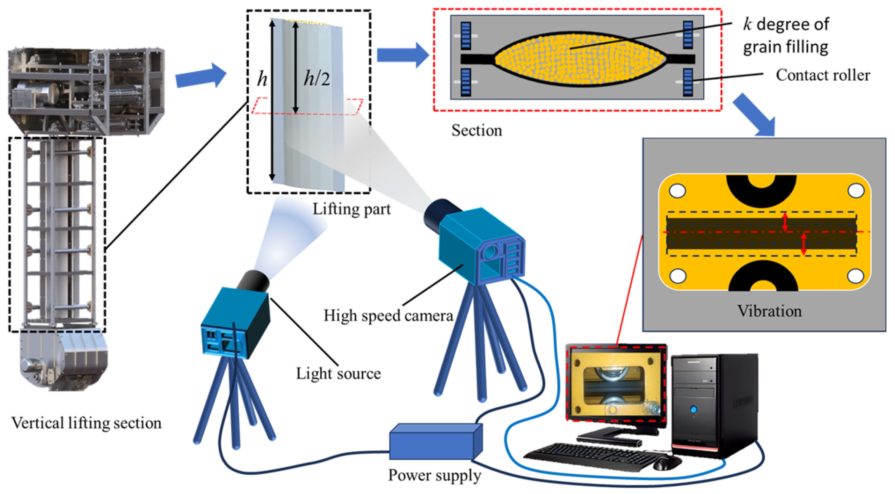
The verification experiment was mainly completed on the established vertical lifting experiment platform of the belt conveyor, as shown in Figure 10. The main devices of the experiment system are as follows: vertical lifting section, control system, feeding device, pressure belt device, power plant, vibration damping, high-definition camera.
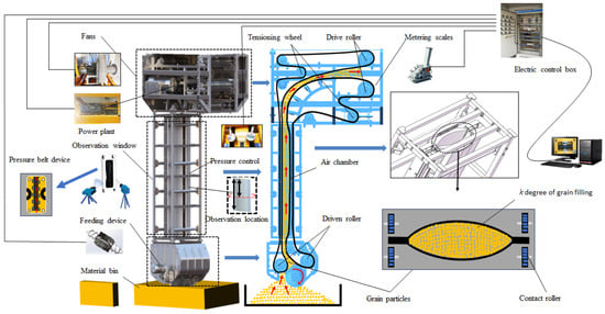
Figure 10.
Clamping process vibration experiment system.
To prevent the effects of outside noise, the experiment was conducted in a closed environment, and the damping material was installed at the bottom to ensure that the experimental results were not disturbed by external noise and vibration.
4.2. Experimental Method
In order to obtain the vibration frequencies of grain vertical structure under different filling conditions, the extreme position and time frequency of the conveyor belt during the vertical conveyance process were captured by a high-definition camera. The frequency of the response at the middle positions h/2 of the vertical lifting section was obtained, and the tested displacement response of this position was equivalent to that of the theoretical calculation response of q1. The relationship of distance and time was obtained by capturing the left and right positions of the belt and the middle horizontal position with the camera. The amplitude and periodic frequency of the left and right flutter of the vertical lifting section were deduced, the vibration displacement curves were fitted using the numerical method. By adjusting the parameters of the feeding device, the lifting parameter was adjusted, which is the value of the grain content k in the cross section of the lifting structure material column. The experimental principle is shown in Figure 11.

Figure 11.
Experimental principle.
In the experiment, first, we recorded video footage using the high-definition camera, then captured the picture shown in Figure 12, and the axis was the equilibrium position of the left and right vibration of the belt. A and B represent the position limit of the left–right vibration of the belt. Sy represents the vibration displacement of the belt from the equilibrium position. The left and right limit position of the belt vibration is shown in Figure 12A,B.
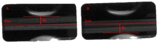
Figure 12.
Belt vibration position: (A) left limit position; (B) right limit position.
The position and time of the belt vibration were obtained from the pixels and frame number of the high-definition camera. The displacement time function of the belt vibration was fitted according to the distance of the belt from the center position and the time interval of the two extreme positions. Then, the frequency of the belt vibration was deduced according to the time function.
4.3. Results of Experiment
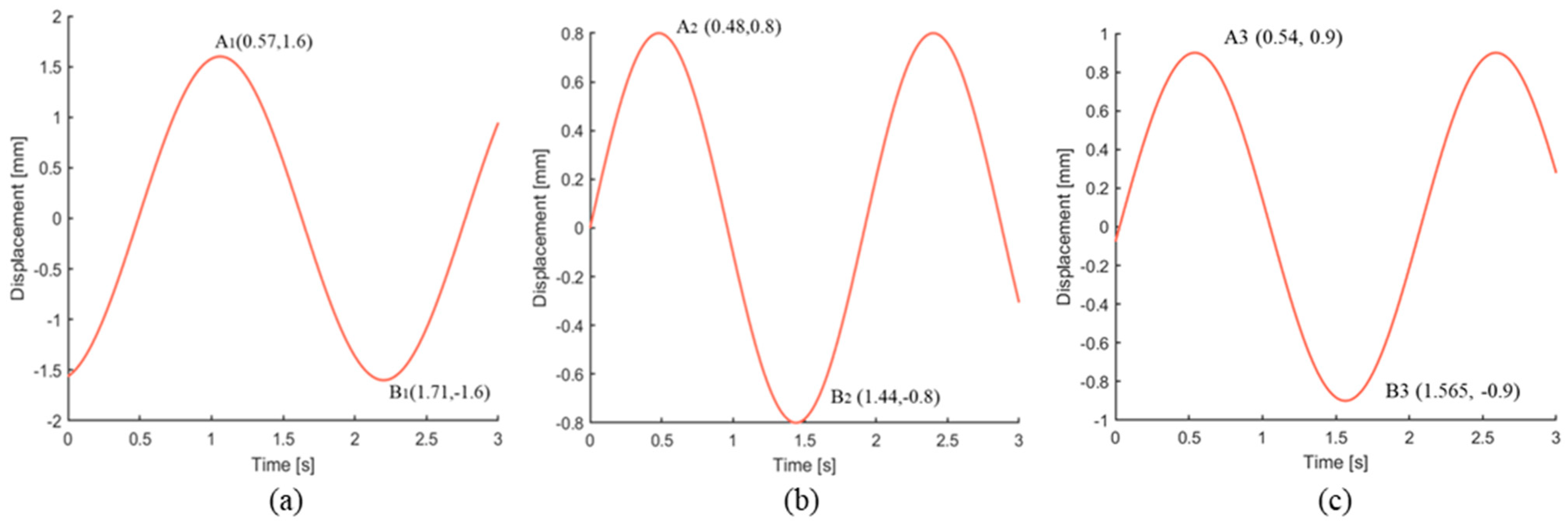
The displacement–time curve of belt transverse vibration at the middle position of the vertical lifting device was obtained according to the results of experiment, as shown in Figure 13.
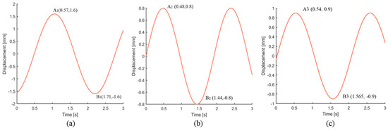
Figure 13.
The response q1 (a) k = 0.1; (b) k = 0.2; (c) k = 0.3.
As shown in Figure 13, the frequencies of the structure were obtained at the different filling degree k. When the filling degree k was 0.1, 0.2, and 0.3, the frequency was 0.4386 Hz, 0.5208 Hz, and 0.4880 Hz, respectively.
5. Discussion
The frequency values of q1 are shown in Table 5. They were calculated based on the vibration differential equation of laminates and the frequency values measured by the experiment, where the degrees of soybean filling were 0.1, 0.2, and 0.3.
Table 5.
Calculated and experimental values of the frequency of q1.
In this study, the vibration of laminated structure was analyzed by normalization. In order to verify the results of experiment and calculation conveniently and accurately, the structural frequency of normalization was restored as calculated values. The equivalent calculated values and experimental values are shown in Table 5.
As shown in Table 5, when the soybean filling degree was in the range of 0.1~0.3, the frequency value increased with the increase of soybean filling, and then decreased. By comparing the experimental values and calculated values under different filling degrees, the errors between them are as follows: 22.3%, 20.7%, 13.2%. This is because the lamination structure is designed to idealize the grain material in the state of compaction as a whole for analysis, and in the actual test, the grain itself is in the discrete grain state. Although the grain layer is in a state of compaction under the action of clamping force, the interaction between particles will affect the overall response frequency of the structure, so the experimental results are different from the calculated results.
In addition, although there was a certain error between the frequency value of the experimental and calculated results, the changing trend of calculated values and experimental values of q1 was consistent. It is fully proved that the research of this paper has certain guiding significance in engineering application.
6. Conclusions
Aiming at the stability of the lifting process of granular materials, this work constructs the vibration model of the vertical segment of the lifting process of granular materials in order to solve the problem of self-excited flutter in the process of grain vertical conveyance, which was caused by the coupling action of airflow gripping and conveyor belt traction. In this study, a nonlinear flutter method is proposed to analyze the vibration of the vertical lifting section of a bulk grain ship unloader. This study provides theoretical support for the design of pressure-supply parameters, overall structure, working operation parameters, and the early warning of the later operation, maintenance, and equipment safety of the following entrainment ship unloader. This equipment and technical support can be useful for the construction of efficient and intelligent ports.
- (1)
- The structure of grain particles in a double-layer belt is simplified into a three-layer composite structure, and the grain material in a vertical lifting belt is laminated based on the theory of layer rationality. The nonlinear vibration differential equation of the vertical lifting section of a grain-carrying ship unloader is established by means of elastoplastic mechanics. The vibration differential equation is solved by perturbation theory and Galerkin discrete analysis.
- (2)
- The vibration response curve and natural frequency of the vertical lifting section of the bulk grain conveyor are obtained by numerical solution, and the proportion of grain in the cross section of the vertical lifting section is analyzed, that is, the effect of grain filling degree k on the vibration response and the natural frequency of the structure.
- (3)
- The experimental platform was built, and the rationality of the theoretical calculated method was verified by the experimental method, which provides a basis and reference for avoiding the occurrence of severe flutter in the conveyance process and improving conveyance efficiency.
Author Contributions
Methodology, M.C., M.W. and P.L.; Writing—original draft, L.Y.; Supervision, Y.L. All authors have read and agreed to the published version of the manuscript.
Funding
This research was supported by the Training Plan of Young Backbone Teachers in Colleges and Universities in Henan Province (2020GGJS088), Opening Subject of Henan Key Laboratory of Grain and Oil Storage Construction and Safety (2021KF-B02) and Science and Technology Research Project of Henan (No. 232102110273).
Institutional Review Board Statement
Not applicable.
Informed Consent Statement
Not applicable.
Data Availability Statement
Not applicable.
Conflicts of Interest
The authors declare no conflict of interest.
Nomenclature
| E1 | Elastic modulus of the rubber belt [Pa] | x* | Equivalent coordinate in the X direction [-] |
| E2 | Elastic modulus of grain material [Pa] | t* | Equivalent time [s] |
| ρ1 | Density of the rubber belt [Kg/m3] | N(v) | Define a function [-] |
| ρ2 | Density of grain material structure [Kg/m3] | No dimensional parameters [-] | |
| k | Degree of grain filling [-] | M | Mass-array operator [-] |
| ρ | Density of the composite structure [Kg/m3] | G | Gyroscope-array operator [-] |
| c | Axial motion speed of the structure [m/s] | K | Stiffness-array operator [-] |
| L | Span length of the laminated structure [m] | γ | [-] |
| E | Elastic modulus of the composite structure [Pa] | E* | Equivalent elastic modulus of the composite structure [Pa] |
| u | Displacement of X directions [m] | T0, T1 | [-] |
| v | Displacement of Y directions [m] | v0, v1 | Displacement at timeT0, T1 [m] |
| F | Tension force [N] | Φn(x) | The nth-order modal function of the system [-] |
| x | Coordinate in the X direction [-] | An(T1) | The nth-order vibration amplitude of the system [-] |
| t | Time [s] | ωn | The nth natural frequency [-] |
| dx | Infinitesimal element in the X direction [-] | v(x,t) | The solution of vibration equation [-] |
| ΔP | Displacement of point P [m] | qr(t) | Time function [-] |
| ΔN | Displacement of point N [m] | φr(x) | Spatial function [-] |
| ds | Length of the microelement segment after deformation [-] | aa | The complex conjugate of the previous term [-] |
| ε | Strain [-] | r | Ordinal number [-] |
| Stress [Pa] | μ | Poisson’s ratio [-] | |
| F0 | Initial tension force [N] | q1 | First-order vibration response [-] |
| A | Cross-sectional area of the structure [m2] | q2 | Second-order vibration response [-] |
| θ | Deflection angle of along the X-axis [-] | Sy | Deviate-center point displacement [m] |
| v* | Equivalent displacement of Y directions [m] |
References
- Zhang, R.; Si, X.; Yang, W.; Wang, N. Analysis of resonance reliability for synchronous-belt transmission with transverse vibration. J. Vibroeng. 2014, 16, 891–900. [Google Scholar]
- Ding, X.; Shen, G.; Tang, Y.; Li, X. Axial vibration suppression of wire-ropes and container in double-rope mining hoists with adaptive robust boundary control. Mechatronics 2022, 85, 102817. [Google Scholar] [CrossRef]
- Bortnowski, P.; Gładysiewicz, L.; Król, R.; Ozdoba, M. Models of Transverse Vibration in Conveyor Belt—Investigation and Analysis. Energies 2021, 14, 4153. [Google Scholar] [CrossRef]
- Bortnowski, P.; Kawalec, W.; Król, R.; Ozdoba, M. Identification of conveyor belt tension with the use of its transverse vibration frequencies. Measurement 2022, 190, 110706. [Google Scholar] [CrossRef]
- Dowell, E.H. Nonlinear flutter of curved plates. AIAA J. 1969, 7, 424–431. [Google Scholar] [CrossRef]
- Bilasse, M.; Azrar, L.; Daya, E.M. Complex modes based numerical analysis of viscoelastic sandwich plates vibrations. Comput. Struct. 2011, 89, 539–555. [Google Scholar] [CrossRef]
- Amabili, M. Nonlinear vibrations of viscoelastic rectangular plates. J. Sound Vib. 2016, 362, 142–156. [Google Scholar] [CrossRef]
- Li, H.; Li, Z.; Safaei, B.; Rong, W.; Wang, W.; Qin, Z.; Xiong, J. Nonlinear vibration analysis of fiber metal laminated plates with multiple viscoelastic layers. Thin-Walled Struct. 2021, 168, 108297. [Google Scholar] [CrossRef]
- Ragb, O.; Matbuly, M.S. Nonlinear vibration analysis of elastically supported multi-layer composite plates using efficient quadrature techniques. Int. J. Comput. Methods Eng. Sci. Mech. 2022, 23, 129–146. [Google Scholar] [CrossRef]
- Bert, C.W. Classical lamination theory. In Manual on Experimental Methods for Mechanical Testing of Composites; Springer: Dordrecht, The Netherlands, 1989; pp. 11–16. [Google Scholar]
- Maji, A.; Mahato, P.K. Development and applications of shear deformation theories for laminated composite plates: An overview. J. Thermoplast. Compos. Mater. 2022, 35, 2576–2619. [Google Scholar] [CrossRef]
- Li, D. Layerwise theories of laminated composite structures and their applications: A review. Arch. Comput. Methods Eng. 2021, 28, 577–600. [Google Scholar] [CrossRef]
- Tho, N.C.; Cong, P.H.; Zenkour, A.M.; Doan, D.H.; van Minh, P. Finite element modeling of the bending and vibration behavior of three-layer composite plates with a crack in the core layer. Compos. Struct. 2023, 305, 116529. [Google Scholar]
- van Hai, N.T.; Hong, N.T. Novel finite element modeling for free vibration and buckling analysis of non-uniform thickness 2D-FG sandwich porous plates using refined Quasi 3D theory. Mech. Based Des. Struct. Mach. 2023, 51, 1–27. [Google Scholar] [CrossRef]
- Sayyad, A.S.; Ghugal, Y.M. On the free vibration analysis of laminated composite and sandwich plates: A review of recent literature with some numerical results. Compos. Struct. 2015, 129, 177–201. [Google Scholar] [CrossRef]
- Hedrih, K. Transversal vibrations of the axially moving sandwich belts. Arch. Appl. Mech. 2007, 77, 523–539. [Google Scholar] [CrossRef]
- Hedrih, K. Transversal forced vibrations of an axially moving sandwich belt system. Arch. Appl. Mech. 2008, 78, 725–735. [Google Scholar] [CrossRef]
- Di Rocco, H.O.; Aguiar, J.C. Some applications of perturbation theory in atomic physics. Eur. J. Phys. 2021, 42, 065403. [Google Scholar] [CrossRef]
- Fernández, F.M. Perturbation theory by the moment method and point-group symmetry. J. Math. Chem. 2015, 53, 998–1009. [Google Scholar] [CrossRef]
- Wang, Q.; Wang, Z.; Fan, B. Coupled bending and torsional vibration characteristics analysis of inhomogeneous wind turbine tower with variable cross section under elastic constraint. Appl. Math. Model. 2021, 93, 188–205. [Google Scholar] [CrossRef]
- Salas, A.H.S. The Galerkin Method for Solving Strongly Nonlinear Oscillators. Sci. World J. 2022, 2022, 8141227. [Google Scholar] [CrossRef] [PubMed]
- Wang, J.; Wu, R. The extended Galerkin method for approximate solutions of nonlinear vibration equations. Appl. Sci. 2022, 12, 2979. [Google Scholar] [CrossRef]
- Hongyuan, Z.; Shulin, W.; Chunshan, L.; Jiehan, L.; Zhenxu, W.; Siyu, C.; Hongyi, L. Grain mechanical properties experimental study. J. Agric. Mech. Res. 2024, 46–2, 193–197. [Google Scholar]
- Xu, Z. Elasticity, 4th ed.; Higher Education Press: Beijing, China, 2008; p. 289. [Google Scholar]


Disclaimer/Publisher’s Note: The statements, opinions and data contained in all publications are solely those of the individual author(s) and contributor(s) and not of MDPI and/or the editor(s). MDPI and/or the editor(s) disclaim responsibility for any injury to people or property resulting from any ideas, methods, instructions or products referred to in the content. |
© 2023 by the authors. Licensee MDPI, Basel, Switzerland. This article is an open access article distributed under the terms and conditions of the Creative Commons Attribution (CC BY) license (https://creativecommons.org/licenses/by/4.0/).