Abstract
UAVs can be deployed in many scenarios to provide various types of services via 6G edge communication. In these scenarios, it is necessary to obtain the position of the UAVs in a timely and accurate manner to avoid UAV collisions. In this paper, we consider improved passive localization algorithms aimed at reducing convergence time and adapting to extreme conditions. For the sake of reducing the complexity of signals and ensuring the reliability of receiving processes, we reconsidered the angle between arrival signals as the feature in positioning. Then, according to the characteristics of the positioning process, we draw on the cyclical process of the iterative greedy algorithm to construct the coding, destruction, and reorganization process to guide the movement of the UAV. Moreover, an improved Metropolis criterion is added to prevent falling into the local optimal solution. Finally, the proposed algorithm is verified in the simulation results. The results show that the algorithm can achieve precise positioning and excellent track planning within a small number of iterations, and it reduces the amount of information carried by the signal and convergence time compared with the traditional method.
1. Introduction
In the past decade, unmanned aerial vehicles (UAVs), providing fast service and flexible operation mode, have been widely used in all walks of life [1,2]. Meanwhile, considering the advanced technologies, e.g., 6G edge communication and collaborative operation of UAV swarms, the internal and external positioning of UAV swarms via 6G are the focus of our attention. Conceivably, by combining edge computing and 6G technology, communication latency can be reduced, allowing UAVs to respond to commands faster. This is important for scenarios that require immediate feedback and quick decision-making, such as UAV positioning and flight.
Considering that there are complex environmental situations and frequent electronic interference in the UAV application environment, and traditional UAV autonomous control technology and GPS cannot meet the existing needs, GPS errors will accumulate over time during the positioning process, and the accuracy will gradually be affected by the inertial navigation system, which is obviously not applicable in dense UAV swarms [3,4,5]. Therefore, we can gradually apply passive positioning to the internal communication of actual UAV swarms. According to the characteristics of passive localization, when in closed UAV swarms, passive positioning only requires several UAVs to act as BSs to transmit signals outward, and then other UAVs can passively receive signals to realize their own positioning, which only needs to be based on communication characteristics. From the perspective of users, this way of positioning can effectively protect and hide UAV swarms [6,7,8].
Recently, passive positioning has shown great potential. Liu et al. [9] fused TDOA (time difference of arrival) with DOA (difference of arrival) to achieve passive positioning and discussed the effects of different delays and spatial structures on positioning. Feng et al. [10] used a single-target optimization model to guide the movement of UAV in passive positioning. In the process of UAV flight, Wang et al. [11] used Newton’s iterative algorithm to establish multiple nonlinear equations and then completed the positioning of the formation. Xiong et al. [12] introduced the concept of BR (bistatic range) matrices, which effectively removed noise in passive positioning.
Although passive positioning is less restrictive and more concealed, we can still further improve the method to enhance its advantages. Specifically, (1) most of the literature studies the improvement of mainstream algorithms, such as TDOA and other algorithms that use signal time difference of arrival. However, it is also of great significance to study the use of other characteristics of the signal to construct algorithms. (2) Passive positioning is mostly used in electronic countermeasures for BS–aircraft (base station) or aircraft–aircraft positioning, but it can also be used for internal positioning of UAV swarms in closed environments [13,14,15]. (3) Although there is a consensus to improve positioning using GPS by considering different environments, there is little research on positioning that does not rely on GPS when considering different environments.
Motivated by the above issues, we explore a passive localization system using a small number of geometric factors combined with environmental noise, and a UAV autonomous control system is constructed based on this. In detail, geometric factors contain range and bearing measurements, such as azimuth and TDOA [16,17], among which we select the angle between two arriving signals only to implement the algorithm. In addition, we use for reference the iterated greedy algorithm [18] and give the specific movement strategy of the UAV swarm. The main contributions of this paper are summarized as follows.
- We investigate the application of passive localization in the context of a new user localizing itself rather than the transmitting source by being dynamically received, and we then formulate a localization algorithm based on a hyperbolic position system.
- We establish a 6G edge communication rule inside the UAV independent of the outside world and realize the process of receiving signals and extracting information during the flight of a single UAV.
- We use a greedy iterative algorithm to adjust the current environment. For preventing the algorithm from falling into a local optimal solution, we use Metropolis to construct a corresponding mutation algorithm.
The remainder of this paper is organized as follows. Section 2 enriches the background of the problem and simply establishes various restrictive conditions. The basic environment model, communication model, and positioning model are constructed in Section 3. Section 4 describes the corresponding algorithm process in detail. The experiments and analysis are given in Section 5. Finally, Section 6 draws a conclusion.
2. Materials and Methods
As shown in Figure 1, we consider a UAV air-to-air (A2A) model for independent edge communication via 6G, and the UAV swarm is ordered; that is, each UAV has a specified relative position (SRP) which is known to UAVs. Among them, everyone has simple half-duplex communication capability and limited computing power. However, during the flight, due to various reasons, there are always some small deviations from the SRP. Therefore, the UAV swarm maintains an overall relatively orderly state with local fluctuations, which means although SRP is known, the actual location needs to be determined through communication. In addition, this article assumes that the model is in an area where GPS is not available, and there is no external signal to assist communication during the flight, so the UAV swarm performs positioning, formation adjustment, and communication through the A2A internal link. On the other hand, there are only a limited number of UAVs transmitting signals which do not contain valid information, such as the source UAV number, distance, etc., acting as aerial base stations (ABSs) according to certain rules at the same time, and other UAVs act as APs to passively receive the approach angles of signals.
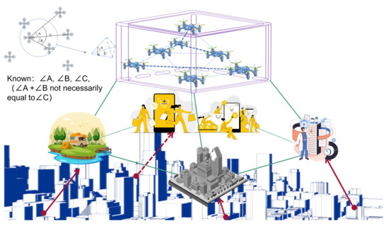
Figure 1.
Overview map of UAV swarm communication.
2.1. Geometrical Model
We take the UAV in the leading position of the formation as the origin of geometric coordinate system :
is the area covered by the internal link communication; , , and are the boundary values of the x-axis, y-axis, and z-axis, respectively; are position offset; and is the speed of the UAV. k is denoted as a vector . The general mobility model of the UAV can be expressed as
where is the inertia coefficient and is the variation in speed. What is more, the displacement model can be represented as
where represents the position of access point (AP) k in time slot , is the time stamp of one slot, and represents white noise which can be regarded as random offsets due to the environment and other factors. We use wind and rain in the environment as the basis for calculating . We consider wind and rain as influencing factors in the actual environment. The formula for calculating the equivalent force of wind at different h is [19]:
where is the size of the wind, C is the drag coefficient (which is set to 0.2), S is windward area, is the average wind speed at h, is is the average wind speed at , h is geometrical height, is the known altitude, and A is the ground roughness factor affected by factors such as terrain, stratification stability, etc., and the value is set to 0.4. Finally, we use
to represent wind forces in three-dimensional space where is the angle between direction of the force of wind and the x-axis and is the angle between direction of the force of wind and the z-axis. Then, we perform a force analysis of the rain. Based on Newton’s second law, the momentum law, and the best raindrop distribution function, the impact force on the structure per unit area is as follows [20]:
where is the density of rainwater, is the final force of a raindrop, is the diameter of raindrops, and is the intensity of rainfall. We use
to represent rain forces in three-dimensional space where is the angle between direction of the force of rain and the x-axis and is the angle between direction of the force of rain and the z-axis. So within the time slot , taking into account wind and rain, the offset is calculated as follows:
where m is the weight of the UAV.
2.2. Communication Model
Regarding the acquisition and the release of the information regarding the angle between two arriving signals (AOAI), on the condition of their containing little valid information in signals, we have formulated three functions for quantification: the monitoring function (), calculation function (), and persistence function ().
is mainly used to record the switch of the action and distinguish the signal batch at the same time.
where ∧ is the logical operation AND, ∨ is the logical operation OR, 0 represents the end of state, and 1 is the beginning of it. Among these, is the specified cut-off time within which signals arriving are grouped into the same batch and its specific value is related to by
where is the time when listening state started and the function expression of is as follows:
where ¬ is the logical operation NOT, and is the longest span in time of the same batch of signals specified in advance. Then, let us quantify the specific by
where represents the angle of arrival of the signal at time t. Finally, we use matrix to store the angle between signals:
When in different environments, the signal will receive interference and attenuation of model strength. So, we add offsets to AS to simulate real-life errors:
where is an equal-sized matrix with only 0 or 1 internal elements to represent the impact of the environment, in which 0 means the signal cannot be received correctly because its strength is attenuated or interfered with and 1 means a signal is received. Therefore, on the basis of obtaining AOAI, the batch calculation can be performed according to the above method.
2.3. UAV Localization via Pass Position
We believe that the UAV swarm has a regular formation at the initial time; that is, each UAV has its SRP. However, various disturbances will occur in actual flight. At this time, if the position of ABP is correct, positioning can be performed by obtaining the relative distance between ABP and the receiver . For the stability of the transmission link, the signal in the A2A internal link does not carry effective information, so the relative distance cannot be directly transmitted. Therefore, we use passive positioning where each AP passively receives signals and uses AOAI obtained by them using the communication model as the signal feature used in passive positioning. In the condition of knowing the AOAI based on the circular angle theorem: the circular angle subtended by an arc is equal to half of the central angle it subtends, and we can be sure that the receiver is located on the only circle with connection with two ABSs as the chord. Considering that this is in three-dimensional space, the center of it should change from a certain point to a three-dimensional ring. From the vector angle formula, we can obtain
Substitute , , simplify, and obtain
where
For convenience of expression, the above formula can be converted into spherical coordinates:
where is the angle between the point and positive z-axis and is the angle between the point and positive x-axis. On the other hand, the radius of circle R is fixed:
From the above formula, we can easily see that the actual position of AP is above the intersection of the torus, and this is very similar to directly obtaining the geometric model of the distance between ABS and AP, so we use as the virtual air base station (VABS). It is convenient to establish the distance equation from the VABP to the receiver:
where is the inner radius of the moving ring calculated by the K UAV through Equation (16e) and is the outer radius of the moving ring calculated by the K UAV through Equation (20).
To solve the above nonlinear equation system, after subtracting the nth equation from the first n − 1 equations, the linear equation is obtained:
where
Solving the above equation by the method of least squares, we obtain
Therefore, in the case that signal has no valid information, the coordinates of the follower can be obtained if the ABS coordinates are correct.
3. Problem Formulation
In this section, we give and optimize the objective function as well as formulate the corresponding problem.
3.1. Optimization Objective
The issue of optimizing the UAV positioning and adjustment aims to minimize the position error in the A-2-A link for independent edge communication via 6G after positioning adjustment and the total number of adjustments, and we formulate a reasonable steering scheme under the constraints of the actual environment. The objective function is as follows:
where s is the number of times the signal is transmitted, is the overall positioning error, M is the number of UAVs, N is the number of iterations, (24b) represents the relationship between weights, and (24c) represents the range of the three-dimensional space considered.
3.2. Problem Statement
Problem (24) tries to minimize the positioning adjustment error and time consumption and the number of operations changing the path under the actual environmental constraints. In this situation, without GPS (global positioning system) and just relying on internal links for communication, only with a passive location algorithm based on AOAI can the position of UAV as AP be solved by their distance from VABS if the position of ABS is correct. However, the above method not only needs to know the number of source ABS but also relies too much on the accuracy of the ABS location, which cannot be guaranteed during the actual flight. This is unacceptable if the UAV has strict anti-collision requirements in formation. On the other hand, in the UAV position adjustment stage in the positioning process, how to plan a suitable route according to the current situation is also of great significance.
Faced with such a complex problem, traditional methods are unable to effectively solve it. Fortunately, passive positioning and the greedy strategy can solve this problem well. We optimize the angle-based passive positioning through a greedy iterative algorithm so that when part of the signal emitter is unknown and the position of ABS is in error, the UAV swarm can be achieved with fewer iterations and accurate positioning. Then, we reconstruct the environment perception model, and we also use the greedy idea to optimize the trajectory of the UAV to meet the anti-collision requirements.
4. Algorithm Design
According to the unique features discussed above, based on the positioning model, we first use the communication rules of passive positioning to obtain the position information represented by AOAI to achieve positioning so as to adapt to the acceptance of position information in the absence of GPS and the complex external electromagnetic environment.
Then we propose an improved iterative greedy algorithm according to the scene characteristics and formulated the rules for destruction and used the greedy strategy to guide the formulation of flight strategy according to the environment model. The reasons are as follows: (1) The iterative greedy algorithm can quickly find the locally optimal solution and gradually approach the optimal solution. (2) Actively destroying the obtained strategy can avoid falling into the local optimal solution. (3) The multiple updates of the greedy algorithm can help UAVs make local adjustments without obtaining global information.
4.1. Coding Rules
We define the position vector to be the encoding of the UAV swarm, and the value in C represents the actual position of the UAV. Considering that each item of C represents a strategy, the corresponding strategy space S is the possible position fluctuation range of the UAV:
When it comes to encoding initialization, we need to initialize C, which is the actual position of the UAV before the start of positioning, and , which is the SRP of each UAV. Since is unknown to the UAVs, from the perspective of the algorithm, the initial strategy is unknown, so the swarm can only infer and reconstruct the code through communication. In addition, the code update performed by each UAV is only known to itself. From a global perspective, a single UAV does not know the overall strategy and can only update its corresponding code during the code update process.
4.2. Greedy-Based Local Search
There is a deviation in the position of the ABS, so Equation (23) does not yield a unique solution. The set of this group of circles is
where are the center coordinates and N is the number of circles. Considering the offset of the ABS position, the possible set of offset circles is
Use , , and to represent the projection equations of on the x-y, y-z, x-z plane, and then calculate the similarity of projection between and , where the similarity is expressed by the arithmetic mean of the overlapping areas of the projections:
where the upper and lower bounds of the integral are the intersection points between the projections. Furthermore, the weight of each ring can be expressed as
where the closer is to 0, the more similar the ring is to the result calculated using the wrong position, that is to say, the greater the possibility of error. Therefore, we assign small weights to reduce the impact in subsequent calculations, so as to select the optimal method in a single iteration. Then, based on the movement speed of the UAV, use the center of circle obtained in formula (32) multiplied by and get coordinates:
Combine the coordinates with the AP’s SRP to form a vector r:
where r is the next adjustment direction and step size of the UAV numbered c, so the encoding for it becomes
So far, a greedy search for a single UAV is completed.
4.3. Reconstruction and Destruction
When a cluster adjustment is made using a cyclic greedy strategy, there is a possibility of the following situation: At the beginning, UAVs will have irregular position errors, and if the error in the local area happens to be a distance away from the ABS as a whole, then the calculated fight position will also be offset by the same distance from the ABS. In this case, the loop stops directly when the UAV moves to the calculated wrong position, so we need to add the destruction and reconstruction rules to circumvent this situation.
The destruction function is used to prevent the algorithm from converging on a local optimal solution. We first extract the unchanged part from the code that completes the greedy-based local search as and the rest as . And then, it is indispensable for us to determine the range of offset values to avoid outliers. In this paper, the distribution of the offset value is defined as a Gaussian distribution with mean a and variance b. In the subsequent reconstruction function, we obtain the acceptance probability according to the number of iterations:
where e is the current iteration count, and the mutation rule is to randomly move the distance in any direction. The principle of this mutation is that when the number of iterations increases, the probability of mutation decreases, and only when the current position is determined to be error-free is there a probability of position mutation. After each destruction, the process of encoding reconstruction needs to be accepted according to the probability; that is to say, the process of reconstruction is actually to judge whether the destruction function is accepted.
4.4. Loop Structure and Complete Algorithm Process
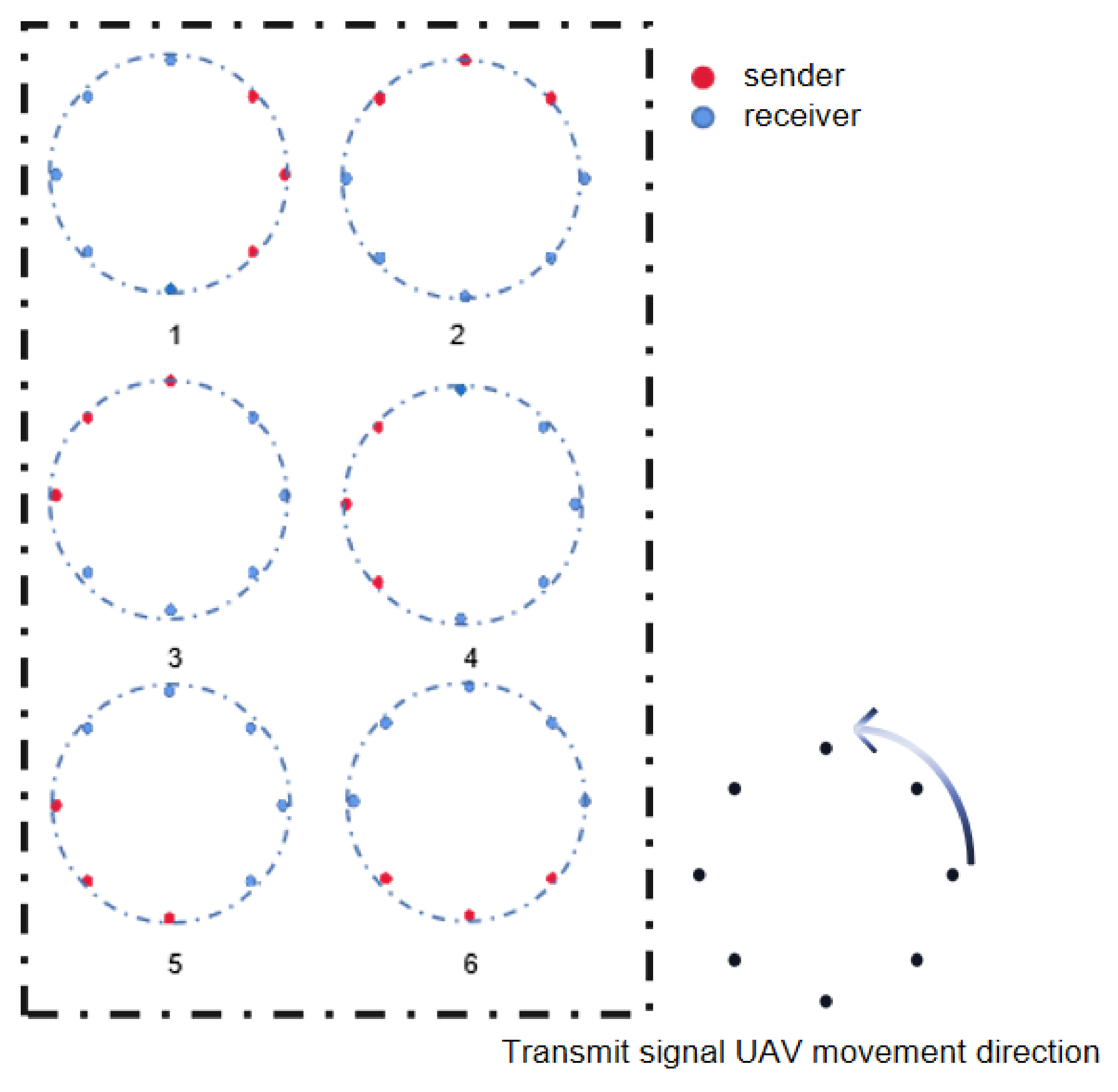
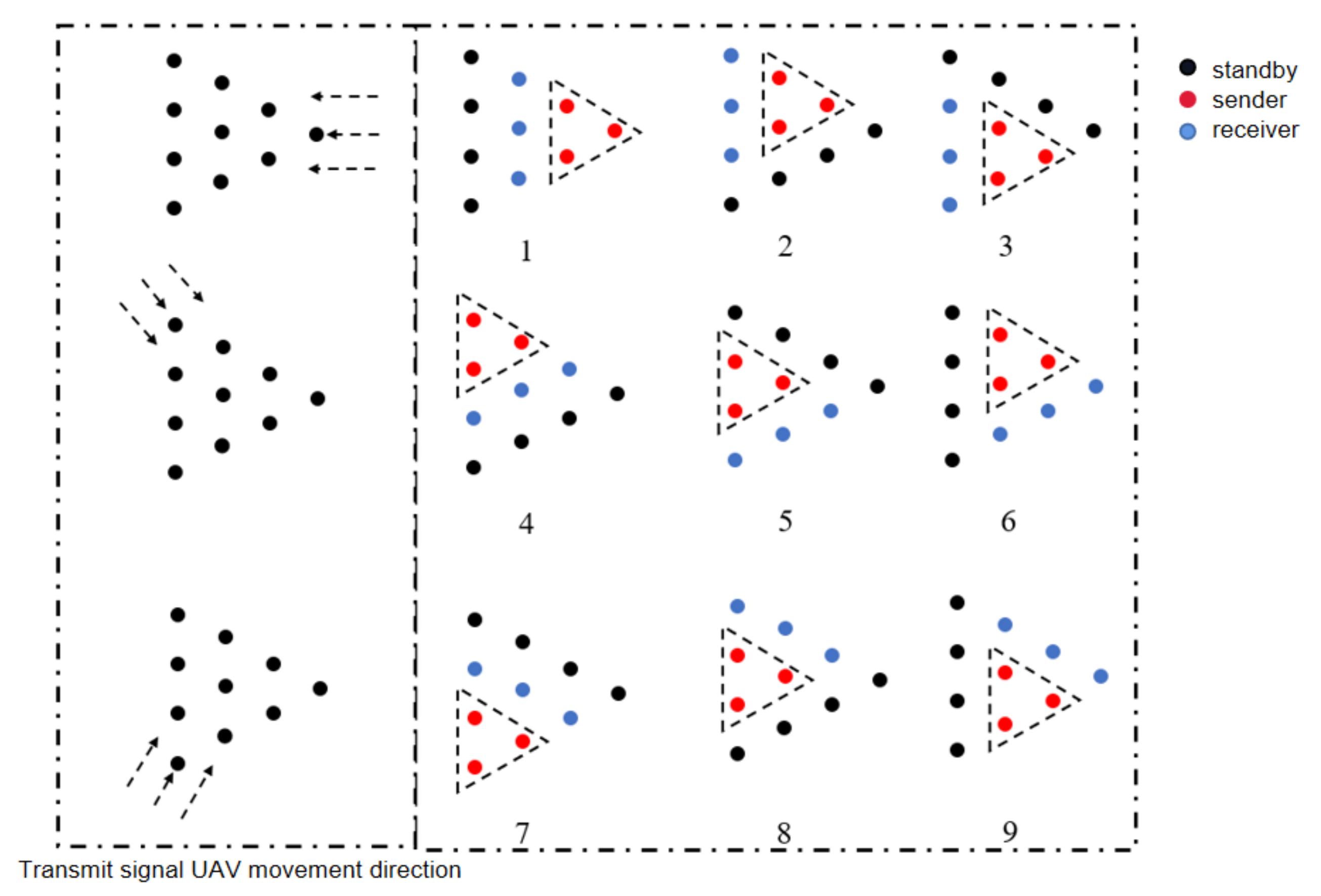
Since the overall coding is unknown to a single UAV, it can only adjust its own position singly in one loop, so we added a nested loop to the original iterative structure. We use the order in which the ABS emits signals as the rule for iteration. As shown in Figure 2 and Figure 3, the slice of the formation is divided into two parts: polygons (with corners) and circles (with arcs), and circles and polygons are analyzed using circles and equilateral triangles, respectively. For an equilateral triangle (Figure 3), the launch sequence is to start from the top corner and move to the opposite side according to the scale of three UAVs. The UAV that is adjusted after each signal transmission is the positioning point for the next transmission signal so that the positioning points are optimized before use to ensure the accuracy of positioning. And after a complete iteration, all UAVs in the formation have adjusted their positions three times, which is very even. The same is true for the circles (Figure 2). The framework of the IGA Algorithm 1 is:
| Algorithm 1: Enhanced Iterative Greedy Algorithm |
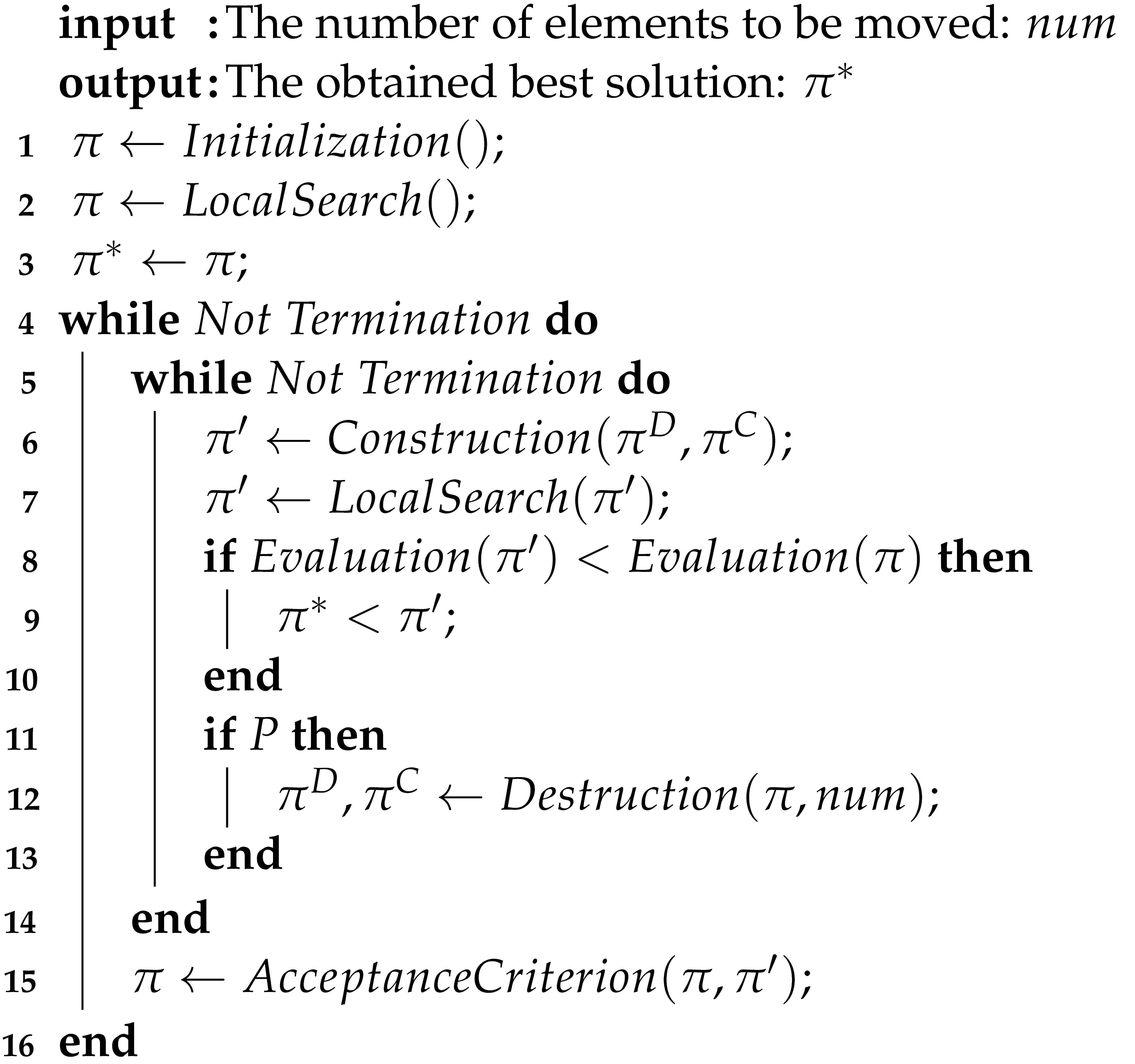 |
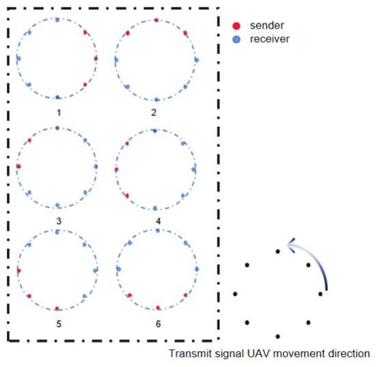
Figure 2.
Polygon array signal reception strategy.
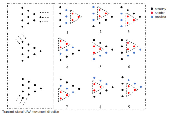
Figure 3.
Circular formation signal reception strategy.
5. Results
In this section, we evaluate the performance of the enhanced iterative greedy algorithm and passive localization through extensive experiments and analyze the validity of the proposed method plus its superiority over baselines.
5.1. Experimental Settings
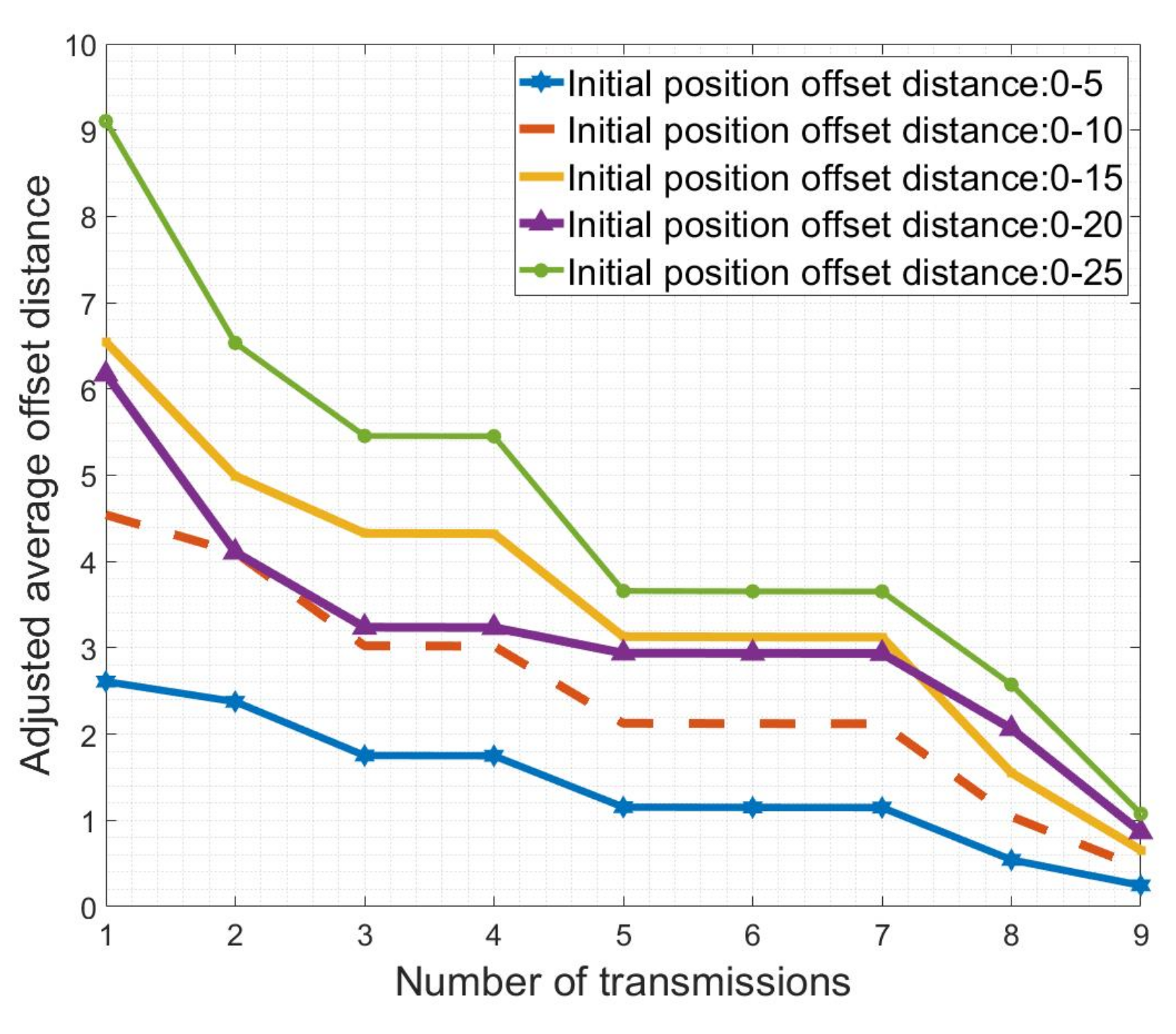
We have chosen two formations of UAVs; the numbesr of these are 7 and 10. Then, we simulate thed positioning and adjustment scheme of the above method by simulating the UAV array and adding environmental factors. We generated random numbers on a given UAV array via Matlab to scramble the UAV array. In summary, we selected cases where the error is 0–5, 0–10, 0–20, and 0–25 unit length for specific analysis. At last, we compared our algorithm with TDOA, DP, and centroid localization algorithms.
5.2. Experimental Results
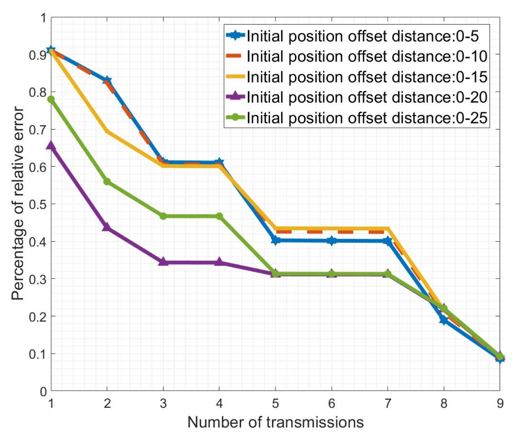
In Figure 4 and Figure 5, we calculated the errors of different ranges: 0–5, 0–10, 0–15, 0–20, 0–25, etc. Each range has two characteristics of the normal distribution and mean distribution. Figure 4 reflects the absolute error in the process of UAV course correction, and it describes the relative error in the process, that is, the ratio of absolute error to its expectation. We can clearly see that although position error after iterations will increase accordingly; they all converge in the end and stabilize below two unit lengths. At the same time, combined with the error ratio curve in Figure 5, we can see that the ratio between final error and distance is stable at about 0.1, so the algorithm for adjusting position is considered to be excellent.

Figure 4.
Positioning error at different degrees of offset.

Figure 5.
Proportion of positioning error.
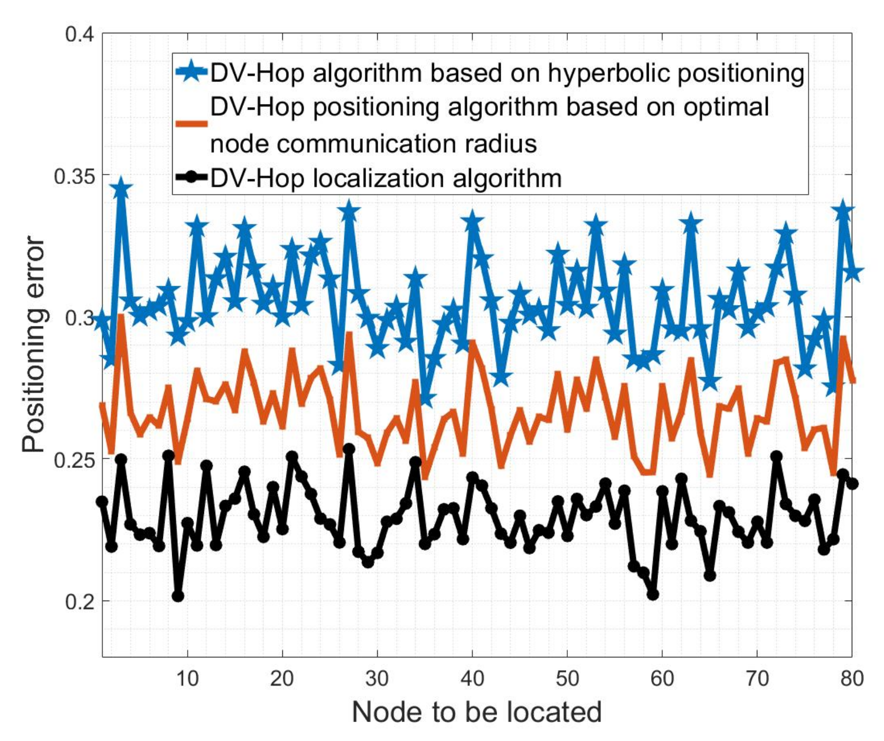
Then, we compared the errors of other algorithms. After our many experiments, we obtained the performance trend of the commonly used DV algorithm and TDOA algorithm. The performance of the above algorithm is independent of the number of iterations, and multiple trials are only to avoid accidental events. Detailed experimental results are found below. Figure 6 shows three improved DV-hop positioning algorithms, among which the error of the algorithm with the best performance is still above 0.2. Figure 7 is the TDOA algorithm based on Chan’s law. We have calculated the error under different numbers of positioning points. It can be seen that the error ratio of the algorithm fluctuates between 0.1 and 0.7. From the trend in the graph, we can see that the error fluctuates between 0.1 and 0.7, and only a few specific experiments have an error below 0.1.
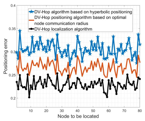
Figure 6.
Positioning error of multiple DV algorithms.
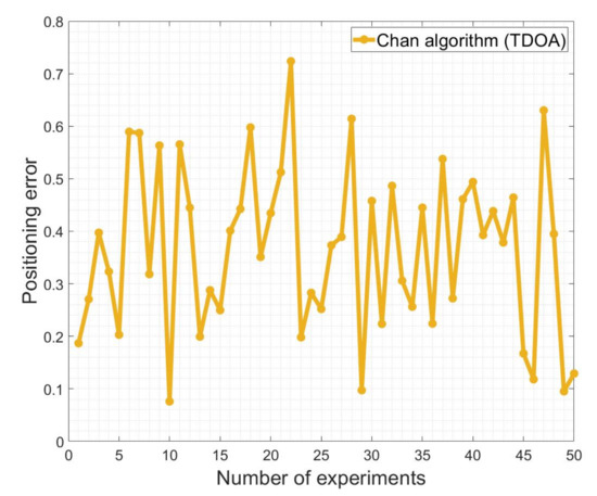
Figure 7.
Positioning error of TDOA.
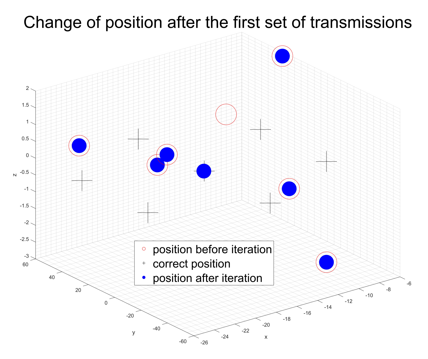
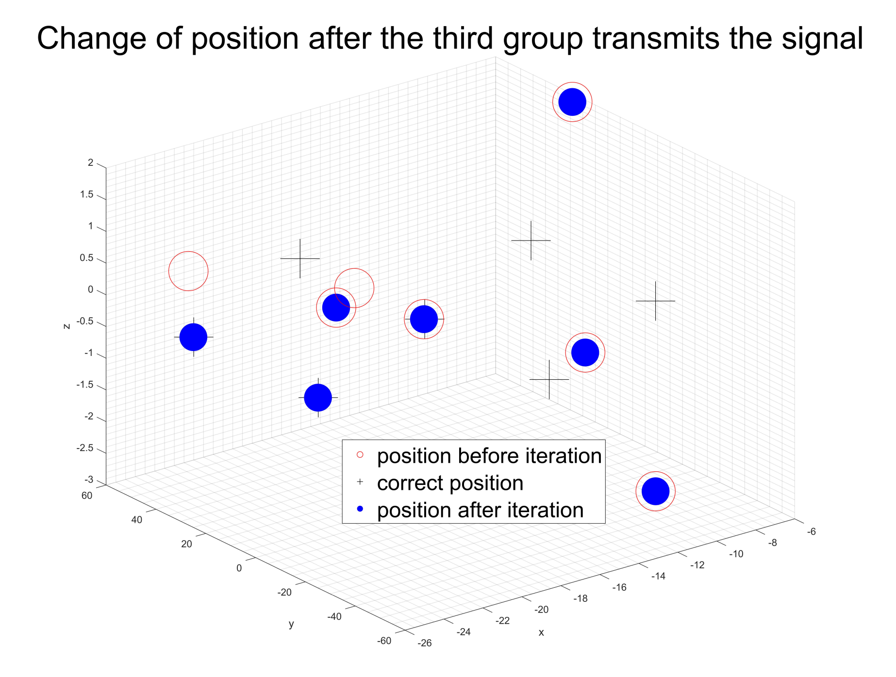
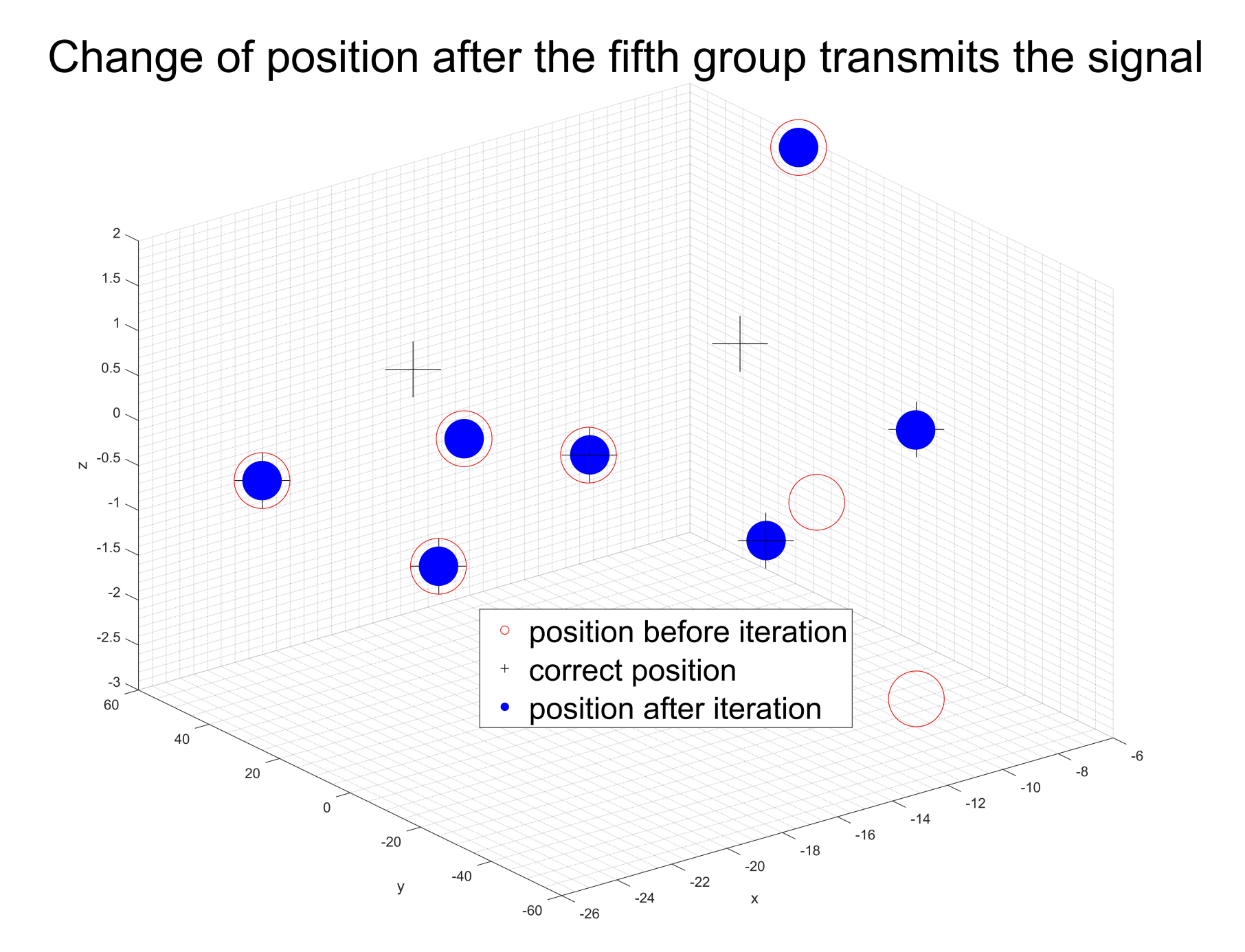
Last, we chose a case where the initial error is between 0 and 15 unit lengths and which follows normal distribution to show the iterative process. Figure 8, Figure 9, Figure 10 and Figure 11 shows that when we transmit signals according to the rule of Figure 2 and Figure 3, after the ninth group of UAVs completes launch, the flight array basically returns to its correct position, so the algorithm can realize the position adjustment within one complete iteration.
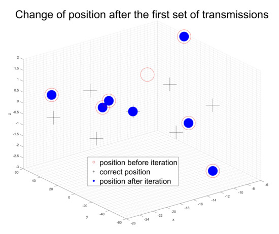
Figure 8.
Formation situation after one iteration.
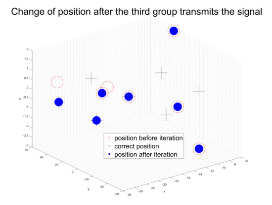
Figure 9.
Formation situation after three iterations.
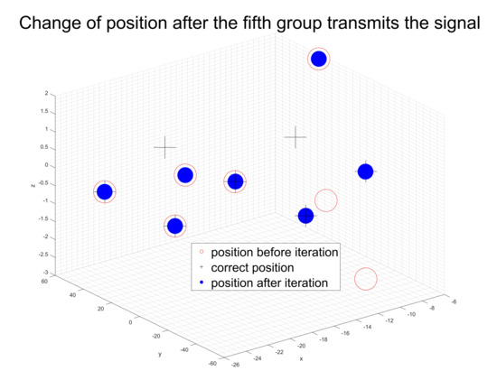
Figure 10.
Formation situation after five iterations.
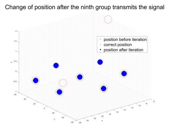
Figure 11.
Formation situation after nine iterations.
6. Conclusions
In this paper, we discuss UAV localization, signal constraints, and optimal course adjustment. In order to solve the problem of applying passive positioning to the positioning of UAVs, we first proved the minimum number of launch base points and launch rules in the formation. After that, we added it into the greedy iterative algorithm to obtain the most general route planning. In addition, for preventing the algorithm from falling into a local optimal solution, we used a mutation algorithm to optimize the overall route. The final experimental results prove that our algorithm can achieve positioning and route planning within a small number of iterations, and the error ratio of the final adjustment scheme is concentrated below 0.1, which has good interpretability and robustness. Finally, the comparison results with other algorithms show that we can consider our scheme reliable in restricted contexts.
Author Contributions
Conceptualization, Y.H.; methodology, Y.H. and Y.J.; software, Y.J.; validation, Y.J.; writing—original draft, Y.H.; writing—review&editing, Y.L.; supervision, X.H. All authors have read and agreed to the published version of the manuscript.
Funding
This work is supported by National Natural Science Foundation of China under Grant No. 62271190.
Institutional Review Board Statement
Not applicable.
Informed Consent Statement
Not applicable.
Data Availability Statement
Data available in a publicly accessible repository. The data presented in this study are openly available in https://github.com/AWAYLLL/Autonomous-Control-System.git, accessed on 24 September 2023.
Conflicts of Interest
The authors declare no conflict of interest.
Abbreviations
The following abbreviations are used in this manuscript:
| UAVs | Unmanned Aerial Vehicles |
| AOAI | Angle between Two Arriving Signals |
| SRP | Specified Relative Position |
| ABS | Aerial Base Station |
| AP | Access Point |
| TDOA | Time Difference of Arrival |
| DOA | Difference of Arrival |
| BS | Base Station |
| GPS | Global Positioning System |
| BR | Bistatic Range |
References
- Yang, X.; Lin, D.; Zhang, F.; Song, T.; Jiang, T. High Accuracy Active Stand-off Target Geolocation Using UAV Platform. In Proceedings of the 2019 IEEE International Conference on Signal, Information and Data Processing (ICSIDP), Chongqing, China, 11–13 December 2019; pp. 1–4. [Google Scholar] [CrossRef]
- Wang, S.; Han, Y.; Chen, J.; Zhang, Z.; Wang, G.; Du, N. A Deep-Learning-Based Sea Search and Rescue Algorithm by UAV Remote Sensing. In Proceedings of the 2018 IEEE CSAA Guidance, Navigation and Control Conference (CGNCC), Xiamen, China, 10–12 August 2018; pp. 1–5. [Google Scholar] [CrossRef]
- Zhang, W.; Zhang, Q.; Zhang, T.; Zhao, Q.; Fu, S. Research on Interference Coupling Mechanism and Test Method of UAV in Complex Electromagnetic Environment. In Proceedings of the 2021 13th International Symposium on Antennas, Propagation and EM Theory (ISAPE), Zhuhai, China, 1–4 December 2021; pp. 1–3. [Google Scholar] [CrossRef]
- Zhu, L.; Xu, Z.; Wang, Y. Research on UAV route optimization in complex terrains. In Proceedings of the 2021 IEEE/AIAA 40th Digital Avionics Systems Conference (DASC), San Antonio, TX, USA, 3–7 October 2021; pp. 1–6. [Google Scholar] [CrossRef]
- Huang, H.; Zhou, H.; Zheng, M.; Xu, C.; Zhang, X.; Xiong, W. Cooperative Collision Avoidance Method for Multi-UAV Based on Kalman Filter and Model Predictive Control. In Proceedings of the 2019 IEEE International Conference on Unmanned Systems and Artificial Intelligence (ICUSAI), Xi’an, China, 22–24 November 2019; pp. 1–7. [Google Scholar] [CrossRef]
- Anagnostopoulos, K.; Hadjiefthymiades, S.; Feki, M. On the benefits of passive localization in wireless sensor networks. Ad Hoc Netw. 2008, 6, 1245–1262. [Google Scholar]
- Le, H.; Nguyen, D. Benefits of passive localization in static wireless sensor networks with relaxed synchronization. IEEE Trans. Wirel. Commun. 2012, 11, 2224–2229. [Google Scholar]
- Yang, Y.; Ku, W.S.; Xiao, Y. Benefits of passive localization with mobile deployer in wireless sensor networks. IEEE Trans. Mob. Comput. 2015, 14, 1812–1825. [Google Scholar]
- Liu, X.; Jiang, J.; Zhang, Z. Cooperative Passive Location of Multi-UAVs Based on TDOA-DOA Fusion Algorithm. In Proceedings of the 2023 6th International Symposium on Autonomous Systems (ISAS), Nanjing, China, 23–25 June 2023; pp. 1–6. [Google Scholar] [CrossRef]
- Feng, Z.; Zhao, Z.; Jin, Y. Research on pure azimuth passive positioning of UAV based on optimization model. In Proceedings of the 2023 IEEE International Conference on Control, Electronics and Computer Technology (ICCECT), Jilin, China, 28–30 April 2023; pp. 264–270. [Google Scholar] [CrossRef]
- Wang, X.; Quan, A.; Hu, C.; Bi, Y. Research on azimuth-only passive location technology of UAV carrying formation based on Newton iterative algorithm. In Proceedings of the 2023 IEEE 2nd International Conference on Electrical Engineering, Big Data and Algorithms (EEBDA), Changchun, China, 24–26 February 2023; pp. 1514–1517. [Google Scholar] [CrossRef]
- Xiong, W. Denoising of Bistatic Ranges for Elliptic Positioning. IEEE Geosci. Remote Sens. Lett. 2023, 20, 3500503. [Google Scholar] [CrossRef]
- Siting, P.; Qian, Z.; Yichao, M.; Jixiang, J. Research on the Technology of Cooperative Dual-Station position Based on Passive Radar System. In Proceedings of the 2020 3rd International Conference on Unmanned Systems (ICUS), Harbin, China, 27–28 November 2020; pp. 1–6. [Google Scholar] [CrossRef]
- Navrátil, V.; Garry, J.L.; O’Brien, A.J.; Smith, G.E. Exploiting Terrestrial Positioning Signals to Enable a Low-Cost Passive Radar. IEEE Trans. Aerosp. Electron. Syst. 2018, 54, 2246–2256. [Google Scholar] [CrossRef]
- Li, J.; Ran, M.; He, Y.; Yang, J.; Li, X.; Wan, Q. Passive Positioning from Azimuth Difference of Opportunistic Signals Without Attitude Measurement. In Proceedings of the 2022 7th International Conference on Communication, Image and Signal Processing (CCISP), Chengdu, China, 18–20 November 2022; pp. 406–412. [Google Scholar] [CrossRef]
- Yao, S.; Meng, Q.; Zhou, C.; Li, G.; Guo, S. The TDOA-Based Kalman Filter for Trajectory Tracking. In Proceedings of the 2022 IEEE 22nd International Conference on Communication Technology (ICCT), Nanjing, China, 11–14 November 2022; pp. 309–312. [Google Scholar] [CrossRef]
- Wang, Y.; Chen, J.; Yang, W.; Men, Z.; Zhang, R.; Sun, X. Moving Target Velocity Estimation Using Multi-Azimuth Angle Mode. In Proceedings of the IGARSS 2019—2019 IEEE International Geoscience and Remote Sensing Symposium, Yokohama, Japan, 28 July–2 August 2019; pp. 377–380. [Google Scholar] [CrossRef]
- Feo, T.A.; Resende, M.G.C. Greedy randomized adaptive search procedures. J. Glob. Optim. 1995, 6, 109–133. [Google Scholar] [CrossRef]
- Lauderdale, T.A.; Pradeep, P.; Edholm, K.M.; Bosson, C.S. Separation at crossing waypoints under wind uncertainty in urban air mobility. In Proceedings of the AIAA AVIATION 2021 FORUM, Virtual Event, 2–6 August 2021; p. 2351. [Google Scholar]
- Lee, L.; Pang, B.; Low, K.H. Environmental Data Analytics for Safe Drone Operations in Low-Altitude Urban Environments. In Proceedings of the AIAA AVIATION 2022 Forum, Chicago, IL, USA, June 27–1 July 2022; p. 3405. [Google Scholar]


Disclaimer/Publisher’s Note: The statements, opinions and data contained in all publications are solely those of the individual author(s) and contributor(s) and not of MDPI and/or the editor(s). MDPI and/or the editor(s) disclaim responsibility for any injury to people or property resulting from any ideas, methods, instructions or products referred to in the content. |
© 2023 by the authors. Licensee MDPI, Basel, Switzerland. This article is an open access article distributed under the terms and conditions of the Creative Commons Attribution (CC BY) license (https://creativecommons.org/licenses/by/4.0/).