Abstract
Multiphase electric motors in cooperation with power semiconductor converters belong to the future of electric drives. This is because of their better properties compared to three-phase motors, such as better fault tolerance. How a multiphase motor will behave in a fault state is very important when using such motors in EV and HEV. This is the basis of the research in this article; we investigate the options for operating a five-phase motor in a fault condition in order to improve the drive qualities during fault operation. The complete mathematical expressions of the five-phase induction motor model in the normal operation as well as in fault operation and also the control modification to improve the properties of the drive are presented. The new five-phase field-oriented control is next described, which improves the drive qualities in four-phase operation and is the first fundamental aspect of the study. Another important aspect of the project is the development of a specific control on a real motor, followed by measurements of properties of a five-phase motor in normal and fault operation of one phase without and with control modification to enhance drive characteristics. The qualities and appropriateness of employing a five-phase motor as a drive in EV and HEV are then determined by comparing these results. Finally, a comparison of motor attributes is shown with and without control adjustment.
1. Introduction
Internal combustion engines are already being phased out in favor of electric motors. There are various reasons for switching from combustion to electric propulsion. The primary issue is the environmental pollution caused by internal combustion engines, which is greatly reduced by the usage of electric driving. As a result, electric motors in the automotive sector are presently undergoing extensive study in order to enhance their qualities and enable the use of electric or hybrid electric cars. Three-phase motors are the most-often-utilized electric motors in electric cars [1,2,3]. The reason for this is that they have been meticulously examined, both in terms of structure and control and functioning. However, additional improvements to the three-phase electric drive are now small, and it is not believed that the drive will be substantially enhanced in this regard. This is where multiphase electric motors come in handy. Multiphase electric motors have lower current per phase, less torque ripple, better noise characteristics, more torque, higher efficiency, and, most importantly, superior fault tolerance than three-phase machines [4,5].
Machine fault tolerance, or the running of a machine in a fault condition, is critical in the usage of electrical machines as a drive for automobiles, planes, or ships. In these instances, the machine must be capable of working with the least amount of power loss and torque ripple, as well as the highest level of efficiency, because there could be catastrophic consequences when the passengers of a given vehicle are endangered.
The purpose of this research is to look at fault-tolerant control on a five-phase induction motor, and to bring new fault-tolerant control that will be easily implemented for any multiphase induction motor. The five-phase induction motor is the most commonly studied multiphase motor in terms of fault tolerance, along with six-phase symmetrical and six-phase quasisymmetrical motors [6].
Another part of the work is the verification of the proposed control scheme on a real five-phase induction motor. The article examines how the performance of the engine in the faulty state with the proposed modification and without the modification is improved.
The fault conditions that are most frequently investigated and that can occur in a five-phase electrical machine are [7,8,9]:
- Failure of one phase;
- Failure of two adjacent phases;
- Failure of two nonadjacent phases.
It should be noted that how the stator windings of an induction five-phase motor are linked is critical.
A five-phase induction motor’s stator winding can be linked in three ways, as will be detailed later. It has three connections: a star connection, a pentagon connection, and a pentacle connection.
It should be observed right away that the five-phase motor is capable of working with one or two phases out. In the case of a single-phase failure, research of the five-phase induction motor in the different stator winding connections in the literature [10,11] has revealed that the most acceptable option is a pentagon connection. With this connection, the induction motor can operate at a reduced power of 10%. When connected to a star, it is 20%. When connecting to a pentacle, the authors mention that this connection is not suitable for operation in the event of a failure of one phase. A comprehensive evaluation of the behavior of a five-phase induction motor in hazardous conditions is given in [12]. The result of the article is that the most advantageous compromise for the design of the drive is the pentagon connection. This stator winding connection provides the optimum ratio of shaft power and torque to motor losses in a failure state. Moreover, the pentacle connection has the finest qualities in regular operation. As a result, it would be most desirable to run a five-phase motor in a pentacle connection and switch to a pentagon connection during fault operation. Other papers [13] provide simulations of a five-phase induction motor operating in single-phase failure mode. As a consequence of these articles, the five-phase induction motor in the star connection may run normally, but with reduced power.
Recent studies on the fault tolerance of five-phase machines include [14], which used a five-phase induction motor with a power of 3.8 kW and was powered by a two-level VSI. As described in the article, the paper presents an improved direct torque control (DTC) technique based on virtual vector evaluation under open-phase failure conditions. This control technique is derived from the work [15] and the results of both works are compared. The torque ripple in [14] is approximately 1.6 Nm, whereas the torque ripple in the compared DTC control technique [15] is approximately 2.5 Nm. As a result, the ripple was reduced by 36%. The overall result of this work is that the proposed technique produces positive torque fluctuations of approximately 80% and 70% of the rated speed at prefault and postfault conditions, respectively. This restricts the postfault loading capacity of a five-phase induction motor to its full capability beyond 70% of rated speed, which was 12.5% lower than prefault operation.
In [16], fault detection and fault-tolerant control for five-phase induction motors are described. The proposed management method is presented in the article. The result of the article is that torque ripple is reduced by more than 50% compared to non-fault tolerant steering.
Other current work in the field of fault tolerant control includes [17], where for five-phase concentrated full-pitch winding induction motor under open-phase fault, the decoupling transformation matrix is reestablished, and open-phase-fault-tolerant control of five-phase concentrated full-pitch winding induction motor based on rotor field orientation is proposed. The measurement was performed on a five-phase induction motor with a power of 5.5 kW, where it was found that the motor ripple without the use of fault-tolerant control was 14% and after using the proposed fault-tolerant control scheme, the torque ripple was 2%.
However, by employing multiphase electric motors, more degrees of freedom may be employed to increase the drive during a one-phase malfunction. This implies that if a motor phase failure happens, the motor will continue to work normally, although with a 20% reduction in power. Due to the uneven spinning MMF, this will also affect other attributes such as torque ripple and efficiency. This may be avoided by removing the undesirable qualities of the open-phase drive by appropriate involvement in the control of the five-phase motor. Several papers in the literature address the control adjustment to reduce ripple and losses in the motor during one phase failure. The basic principle of this modification is to adjust the control algorithm to ensure spatial distribution of the voltage vectors to achieve sinusoidal distribution of the MMF—magnetomotive force—as described in [18,19]. Specific strategies based on a fault-tolerant control algorithm, including machine and converter nonlinearities, are described in [20,21,22]. Another possibility is to use predictive fault tolerance control in [23]. In [24,25], a technique of reconfiguration of phase currents in a single-phase and two-phase open fault state is presented. In articles [26,27], fault-tolerant control for five-phase permanent magnet synchronous motors is presented.
The paper “Predictive Torque Control for Five Phase Induction Motor Drive with Common Mode Voltage Reduction” [28] presents another technique for fault-tolerant motor control. This paper presents finite state predictive torque control (PTC) for a two-level five-phase induction motor in order to reduce the common mode voltage. The measurements were performed on a five-phase induction motor with a power of 1 kW.
The first major purpose of this study is to offer comprehensive modeling of a five-phase induction drive for normal operation, a condition with a one-phase failure, and a model adjustment to improve the drive’s attributes with a one-phase failure. The equations of the models for these states are included in the article, along with the comprehensive derivation of these equations.
The second key purpose is to create an algorithm that will assure the decrease of torque ripple and the enhancement of drive attributes during a one-phase failure condition. The fault-tolerant control systems published in the literature are based on hysteresis regulator control. These have several advantages, which are detailed in Section 3. In the abcde system, this link has been updated and the hysteresis controllers have been replaced with PI controllers, which gives various advantages, as described in Section 3.2. The main advantage of the new fault-tolerant control is the simple implementation for any multiphase induction motor.
In addition, the work focuses on the experimental validation of the suggested control on a real five-phase induction motor.
Finally, the measurement results will be compared to the results in normal operation and fault situations without control editing, and the acceptability and benefits of utilizing the control scheme during the failure will be assessed.
2. Modeling of Five-Phase Induction Motor
The functioning of a five-phase induction motor is the same as that of a three-phase machine. As a result, modeling a five-phase induction motor follows the same principles as modeling a three-phase motor. The only difference is the number of windings; a three-phase motor has three stator windings that are 120° apart in space and time, whereas a five-phase motor has five windings that are 72° apart in space and time. It is possible to build any n-phase machine in which the angle between the windings is determined by the number of phases, as defined by the relation:
Figure 1 depicts the mechanical distribution of the winding in a five-phase induction machine, with the phase shift between each adjacent phase equal to 72°.
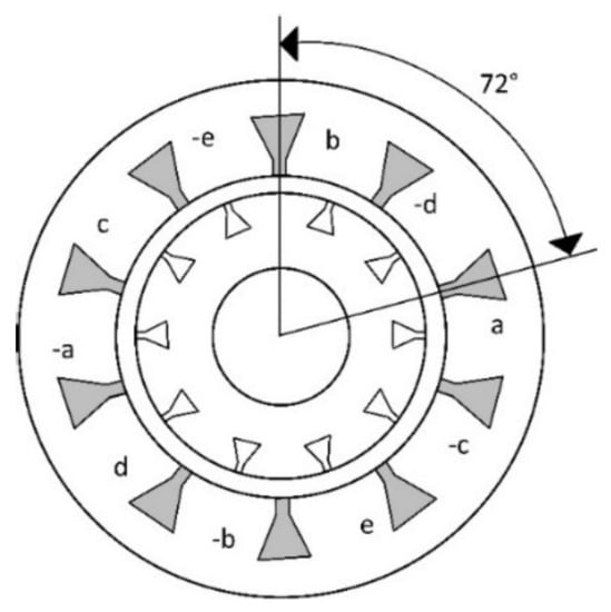
Figure 1.
The mechanical winding layout of a five-phase induction machine.
The five-phase motor, as noted in the introduction, opens up additional possibilities for connecting stator windings. These must be envisioned, and the distinction between these relationships must be expressed. Figure 2 depicts the stator winding connections. This is the fundamental winding connection to the star, as well as the pentagon connection, which is comparable to a triangle connection in a three-phase system. The pentacle connection is another connection that is not common in three-phase machines [29].
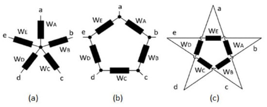
Figure 2.
Possibilities of stator windings connection of five-phase induction machine: (a) star connection; (b) pentagon connection; (c) pentacle connection.
It should be noted that by changing the individual winding connections, the motor will achieve different properties. This fact is given by the phase distribution between the individual connections. This is nice to see in the phase diagrams of the individual connections. It is not necessary to present a phase diagram of the star connection, because the supply voltage applied to the winding phase in this circuit is equal to the supply voltage. When the windings are connected to the pentagon, the voltage from the source of phases a and b is closed on the WA phase of the winding, as can be seen from Figure 3a. The vector voltage sum of this connection will be on the motor phase 1.1756 times higher than the voltage of the source. Figure 3b is a phase diagram for a pentacle connection. Here, the voltage between the a and c phases of the source is closed on the WA phase. In this case, the voltage on the motor winding will be 1.902 times higher than the supply voltage. It is because of these facts that it is necessary to realize that the motor in each connection will have different properties [30,31].
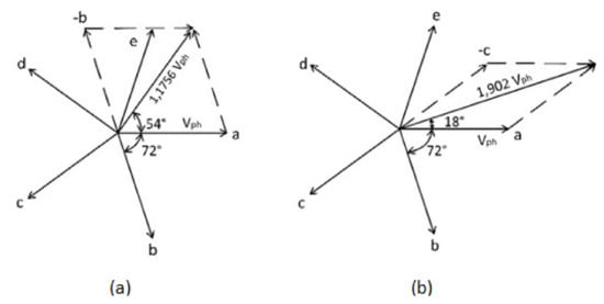
Figure 3.
Phase diagram of a five-phase motor: (a) pentagon connection; (b) pentacle connection.
2.1. Mathematical Model of Five-Phase Induction Motor in Normal Operation
The mathematical description of multiphase machines is an essential element of their research. The mathematical description of a five-phase induction motor in a star connection will be the subject of this subsection. For a motor model in a pentagon or pentacle connection, phase changes between the motor windings must be considered, depending on the connection. As a consequence, the resultant voltage and current amplitude change directly on the motor stator windings without affecting the supply voltage, as seen in Figure 3.
Using (1) is obtained voltages for a symmetrically distributed and balanced five-phase machine:
Decoupling transformation matrix of the five-phase induction motor model:
Voltage stator and rotor equations in reference dq frame:
Flux linkages of stator/rotor:
Torque calculation:
Relation for rotor speed calculation:
where Rs represents the stator resistance; Rr—rotor resistance; Ll—leakage inductance; Lm— represents the maximum mutual inductance of the stator to the rotor; U—voltage; i—current; ψ—flux linkages; J—a moment of inertia; p—number of poles; TL—load moment; Te—electromechanical moment; ωr—angular velocity of the rotor; ω—angular velocity; ωa—the angular velocity at which the machine equations of any reference frame are transformed; and ρF represents d/dt [32,33].
2.2. Mathematical Expression of the Modification of a Four-Phase Operation for a Five-Phase Induction Motor
This subsection provides a detailed mathematical derivation of the phase current adjustment for a sinusoidally distributed MMF for one-phase failure. If one phase is interrupted, either on the motor side, the converter side, or between the motor and the power converter, the resulting MMF changes. For this case is considered the failure of phase a. The resulting force will be expressed as follows:
As it can be seen from (20), the current through phase a is equal to zero. By expressing this equation and subsequent separation into the real and imaginary part we obtain (21) and (22):
The condition for the MMF to be evenly distributed in the one-phase failure is as follows:
In the following steps, a detailed procedure for deriving the phase ib current calculation is given. Equations (24) and (25) represent a suitable substitution from (23) for the expression of current ib:
Relationships (26)–(32) represent the multiplication and expression of currents from (24) and (25):
Thus, (33) is obtained using the formulas for cos (x) − cos (y) and sin (x) + sin (y), which is substituted into (32):
By multiplying the (33) and using the formula cos (x + y), (34) is obtained:
The resulting modifications give the final expression of the current ib for the adjustment of the operation of the five-phase induction motor in a single-phase failure:
In a similar manner, given in (21)–(35), the equations of the other three currents, ic, id, and ie, are obtained, which are given in (36)–(38):
Graphical Representation of the Modification of the Four-Phase Operation for a Five-Phase Induction Motor
Figure 4 depicts a graphical representation of the foregoing mathematical modification of a five-phase induction motor running in phase failure a. This lowers torque ripple while increasing efficiency [34,35]. The graphic shows that phase a is open, hence the current ia is equal to zero. For the remaining four phases, phase shift is determined by (35)–(38).
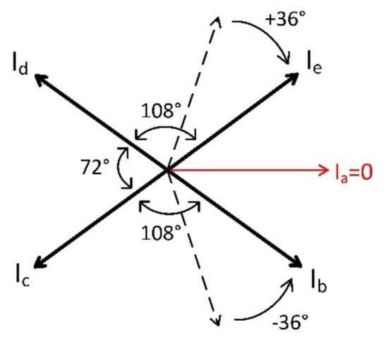
Figure 4.
Graphical representation of the phase current adjustment during operation of a five-phase open-phase induction motor.
If we wish to secure the indicated adjustment during the fault condition, we must change phase e by 36° in the direction of rotation and phase b by 36° in the opposite direction of rotation. This will assure a sinusoidal MMF.
To ensure the phase shifts according to Figure 4, it is necessary to use the special control given in Section 3.2. This appropriate adjustment of the alpha, beta and x, y currents will provide the necessary phase shifts of the motor currents.
3. Five-Phase Induction Motor Control
The one basic part of the article is to investigate the properties of a five-phase induction motor using fault-tolerant control with a one-phase fault. Subsequently, the motor behavior is compared during the normal operation and one-phase failure. In the five-phase mode, the basic field-oriented control scheme was used given in Section 3.1. This control scheme was also used during the one-phase failure measurement. This is because we can comprehensively compare the effectiveness of the fault-tolerant control scheme. Then the control scheme was modified, and it was based on a derived mathematical model with a one-phase failure (New fault-tolerant control) as mentioned in Section 3.2.
As a result, we were able to establish the appropriateness of employing a five-phase induction motor instead of a three-phase motor in EV and HEV, and to develop a novel fault-tolerant control method for multiphase motors.
3.1. Basic Control Scheme Used in Normal Operation during the Measurement
The measurement in normal operation was performed using the scheme of the field-oriented control presented in Figure 5 to compare the machine in normal operation and a one-phase fault operation. The same control method was employed without any intervention in the control for the measurement of the motor with one phase defect.
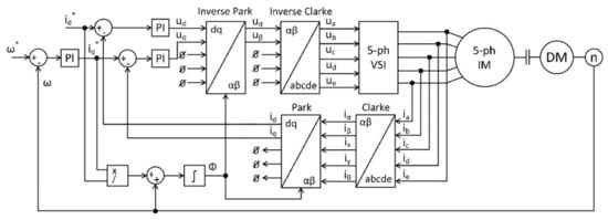
Figure 5.
Scheme of vector control of a five-phase induction machine.
The field-oriented control is well known from three-phase motors. The difference in the five-phase vector control is only in the use of five-phase Clarke and Park transformations, as well as five-phase inverse transformations. In the diagram in Figure 5, the ia–ie currents flowing through the motor are measured. The symbol ω represents the angular velocity of the rotor of a five-phase induction motor, θ represents the rotor flux position. DM represents a dynamometer, VSI is a voltage source inverter. The PI block displays the proportional integration controller [36,37].
3.2. Design of an Algorithm for Adjusting the Control during a Single-Phase Failure to Improve Motor Characteristics
One of the most important aspects that is heavily emphasized is the safety of electric drive in EV and HEV. If the drive fails and the machine is unable to continue operating during traffic, the results could be disastrous. As a result, new driving methods and controls are being implemented to eliminate this risk. As previously stated, one option is to use a multiphase motor, which provides better fault tolerance.
Figure 6 depicts a new control method that ensures normal operation in the event of a phase failure. The original vector control scheme no longer includes the PI current controllers for id and iq, as well as the Park and Clarke transformation. Only the components of the currents iα and iβ are active in the fault-free sinusoidal balanced motor. Components x, y, and 0 are all zero. However, if a phase failure occurs and the MMF is no longer sinusoidal, the situation changes. The motor power decreases as it begins to produce a large ripple torque. The components of the currents x, y, and 0 are also active in this case, and the components of the currents ix and iy are used to eliminate the fault state.

Figure 6.
The fault-tolerant control scheme for a five-phase induction machine.
From the control scheme in Figure 6, by a suitable recalculation of the components of the currents ix and iy using the currents iα and iβ, we can provide again the sinusoidal MMF. In the new control scheme, all required currents from the transformation are then compared with the measured currents and regulated in the PI controllers.
The calculation of the constants K1–K4, which provide again sinusoidal MMF, is given by the solution of the current matrix (39). It has to be considered that in the error phase, the current is zero. In our case, ia = 0.
It should be noted, however, that there are several possible combinations for obtaining a sinusoidal MMF. It is determined by the entry conditions. We concentrated on two conditions during the investigation:
- Symmetrically distributed stator currents;
- Nonsymmetrically distributed stator currents.
In both cases, the torque ripple will be minimized and will be getting closer to the ripple values as in normal operation.
The procedure for calculating the constants K1–K4 for the state of symmetrically distributed currents will be presented in this part.
Relationships (40) and (41) represent the equations used in the control scheme shown in Figure 6. The calculation procedure is given by solving the current matrix (39) with the same current amplitude and zero phase current a.
Figure 7 depicts the plot of Equations (42)–(46). These are currents in the alpha, beta x, y, and zero systems, providing fault-tolerant control.
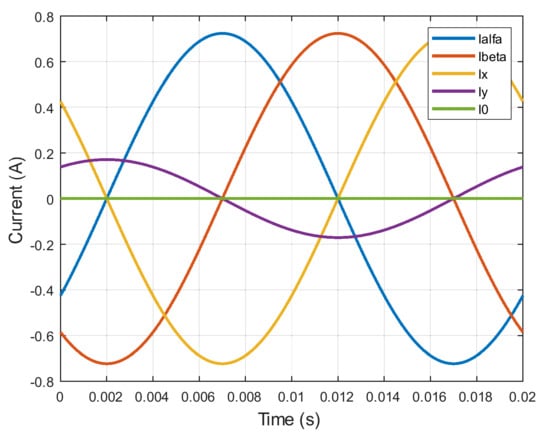
Figure 7.
Currents required to ensure fault-tolerant control.
Subsequently, it is necessary to find the relationship between the currents iα and iβ to ix and iy from these equations of the currents iα, iβ, ix, and iy. Thus, it is necessary to calculate the constants K1–K4:
Table 1 displays the constants K1–K4 for the edit conditions discussed in this article, for which detailed measurements have been taken to indicate the extent to which the motor performance can be improved in a one-phase failure operation.

Table 1.
Table of coefficients K1–K4 for adjustment in the control.
4. Measurement
This section contains the results of actual measurements performed on a five-phase induction motor. All measurements were taken for the fault-free state, the fault state without control editing, the edited control to symmetrical currents, and the edited control to unbalanced currents. The control scheme shown in Figure 5 was used for the first two mentioned states. The scheme in Figure 6 was used in conjunction with Table 1 for the edited control. The measurement scheme is depicted in Figure 8 T1 through T10 are VSI switching transistors, TS is the torque sensor, DM is the dynamometer, and n is the speed sensor. The parameters of the measured five-phase induction motor are shown in Table 2.
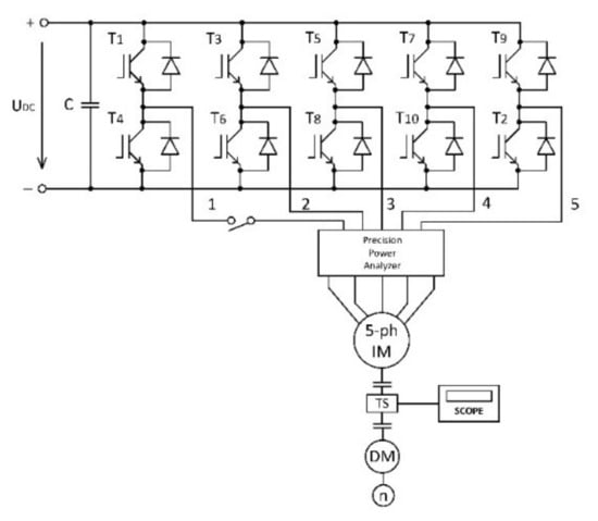
Figure 8.
Measurement scheme of a five-phase induction motor in fault conditions.
Table 2.
Parameters of a five-phase induction motor.
4.1. Measuring Efficiency Comparison
The efficiency of a five-phase induction motor was first measured. The measurement was carried out in accordance with the description in the introduction of Section 4.
Figure 9 depicts the motor efficiency characteristics for all four conditions mentioned. The study is performed out with a nominal motor torque of 3.5 Nm. The blue curve in the figure represents the efficiency of the machine operating without failure and the red curve represents the efficiency of the motor operating in one-phase failure. The gray and yellow curves represent the efficiency during the fault-tolerant control for unbalanced and symmetrical currents, respectively.

Figure 9.
Motor efficiency, rated torque 3.5 Nm.
The efficiency of the motor decreased by 22.51% in the one-phase failure based on these waveforms for the rated parameters of the motor. This is consistent with the theory presented in Section 1, where previous research has shown that a single-phase failure reduces motor power and efficiency by 20%, respectively. This can be improved by employing the fault-tolerant control described in Section 3.2. The motor efficiency characteristics in Figure 8 show that the modification aided in improving motor efficiency. The greatest loss of efficiency occurs at higher speeds (higher power). For example, at a speed of 2500 rpm, the decrease in motor efficiency was 15.65% for unbalanced currents and 11.43% for symmetrical currents.
Motor efficiency characteristics for reduced machine torques were also performed. Figure 10 shows the characteristics for a constant torque of 2 Nm, and Figure 11 shows the characteristics for a motor torque of 1 Nm.
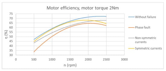
Figure 10.
Motor efficiency, constant torque 2 Nm.
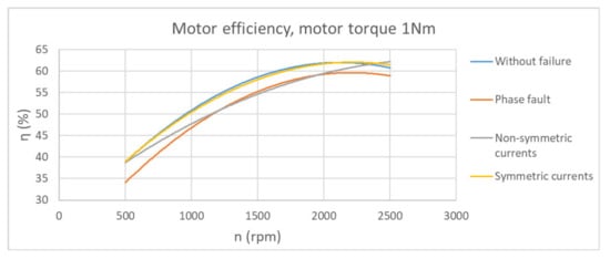
Figure 11.
Motor efficiency, constant torque 1 Nm.
The efficiency characteristics for 2 Nm and 1 Nm show that control editing is still effective and improves motor efficiency with a one-phase failure. In Figure 10 and Figure 11, fault-tolerant control implemented on symmetrical currents has better properties than control implemented on unbalanced currents. Because the symmetrically distributed currents ensure a symmetrically distributed load of the individual motor phases, and the machine is also symmetrically heating.
As shown in Figure 11, the fault-tolerant control to symmetrical currents provides the same efficiency as the fault-free state at reduced torque.
4.2. Measuring the Comparison of Input Powers
Another characteristic that was looked into was the input power at a constant speed. These tests were carried out for three different motor speeds. It should be noted that the measurements were carried out on the same mechanical torque values for all four states, as evidenced by the waveform.
Figure 12 depicts the torque dependence of the input powers and the mechanical power of the motor for a constant speed of 2500 rpm. The waveforms show that in the case of a single-phase failure, the torque must be reduced from 3.5 Nm to 2.7 Nm in order to achieve the rated input power and avoid overloading the power supply system and the motor. This means that the rated motor torque must be reduced by 22.86%. However, if the edited control scheme is used, this decrease is significantly reduced. The nominal torque is reduced by 8.58% when using unbalanced currents and 12.86% when using symmetrical currents.
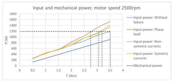
Figure 12.
Dependence of power on torque, constant motor speed 2500 rpm.
Figure 12 also shows how the slope of input power increases due to the fault, whereas the slope of mechanical power remains constant. The fault-tolerant control reduces the amount of power drawn from the power supply while increasing machine efficiency.
Figure 13 and Figure 14 show the same measurement, but at speeds of 1500 rpm and 500 rpm, respectively. With decreasing mechanical torque, the difference between fault-tolerant control for unbalanced currents and symmetrical currents becomes negligible.
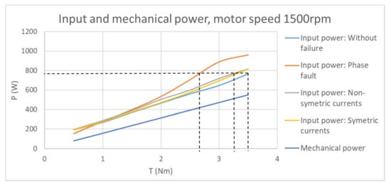
Figure 13.
Dependence of power on torque, constant motor speed 1500 rpm.

Figure 14.
Dependence of power on torque, constant motor speed 500 rpm.
4.3. Phase Currents Comparison Measurement
Another thing to remember is that the motor winding is designed for specific power, so the current should not be exceeded. Otherwise, the motor would be overloaded, reducing its service life significantly. In the event of a phase failure, the total current required to achieve the required mechanical torque will be divided into four phases rather than five. This raises the rms value of the current flowing through the motor phases. As a result, we concentrated on measuring the motor phase currents in this subsection. It should also be noted that the currents during phase failure are asymmetric. As a result, the maximum phase current is used for plotting.
Figure 15 depicts the relationship between the maximum rms currents flowing through the stator phases and the mechanical torque in all four investigated states. According to these waveforms, in order to maintain the rated current of the motor phases, the rated torque must be reduced by 59.43% in the event of a phase failure, i.e., from 3.5 Nm to 1.42 Nm. The decrease is 57.15% when using the unbalanced current control adjustment, and 30.85% when using the symmetrical current control adjustment.
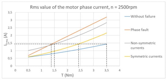
Figure 15.
Dependence of phase currents on torque, constant motor speed 2500 rpm.
Figure 16 and Figure 17 show the motor phase currents as a function of mechanical torque for motor speeds of 1500 rpm and 500 rpm, respectively.
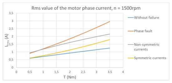
Figure 16.
Dependence of phase currents on torque, constant motor speed 1500 rpm.
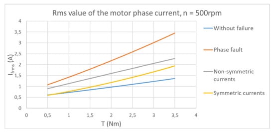
Figure 17.
Dependence of phase currents on torque, constant motor speed 500 rpm.
The measurements in Section 4.2 and Section 4.3 show that the required decrease in moments varies for these two criteria. Section 4.2 describes the necessary reduction in rated torque due to power supply system loading, i.e., the input power cannot exceed nominal values, which is critical for the operation of EV and HEV. Section 4.3, on the other hand, represents the necessary reduction in rated torque in relation to motor loading. However, it should be noted that each machine is designed with some power oversizing, so only the criterion in Section 4.2 must be met for a single-fault condition and control modifications.
4.4. Comparison of Torque Ripple Reduction
The application of a fault-tolerant control strategy has a significant impact on torque ripple during motor operation in phase failure. Torque ripple is closely related to motor noise, and this is an important parameter to consider when designing electric motors for EV and HEV. As a result, it is critical to eliminate it as much as possible when the motor is in a fault state.
This section shows the torque ripple waveforms for each of the four conditions. At a rated load of 3.5 Nm, the motor speed was 2500 rpm. The ripple was measured using a torque sensor with a range of 20 Nm, while 10 V at the sensor output equals 20 Nm.
Figure 18, Figure 19, Figure 20 and Figure 21 depict the torque ripple during normal operation (Figure 18), one-phase fault operation without editing (Figure 19), control editing to unbalanced currents (Figure 20), and editing to symmetrical currents (Figure 21).
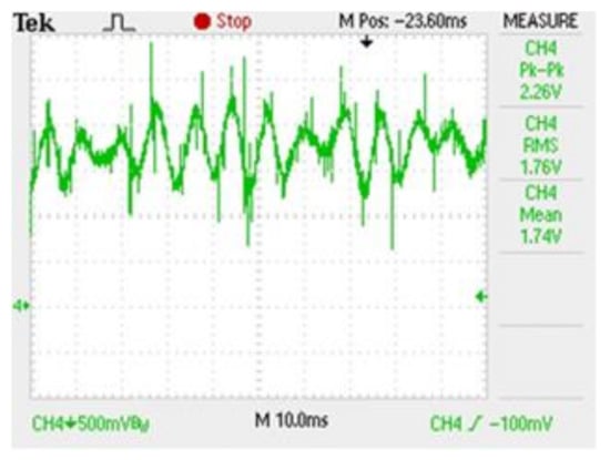
Figure 18.
Torque ripple, normal operation, 2500 rpm, 3.5 Nm.
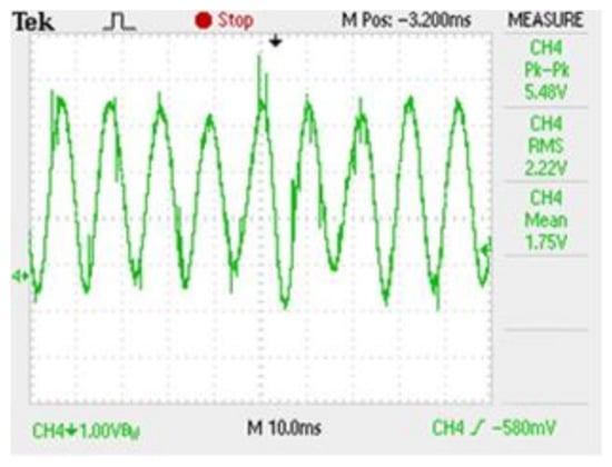
Figure 19.
Torque ripple, one-phase fault operation, 2500 rpm, 3.5 Nm.
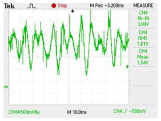
Figure 20.
Torque ripple, edit: nonsymmetric current, 2500 rpm, 3.5 Nm.
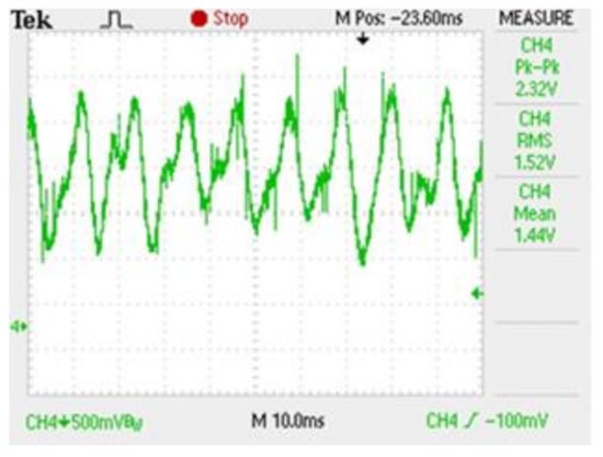
Figure 21.
Torque ripple, edit: symmetric current, 2500 rpm, 3.5 Nm.
The waveforms show that the torque ripple was approximately ±2 Nm during normal operation (Peak to Peak). The torque ripple increased to ±8.8 Nm in Figure 18 during the one-phase failure operation. This represents an increase of up to 440%, which is unacceptably high for an engine operating as an electric vehicle. We were able to reduce the magnitude of the torque ripple to unbalanced currents to ±5.6 Nm using fault-tolerant control and to approximately ±3.8 Nm using symmetrical currents. This represents a more than 50% improvement in the ripple compared to the fault condition.
Figure 22 depicts the torque ripple path for a nominal motor torque of T = 3.5 Nm. The characteristics were covered by a linear line. The torque ripple waveforms show that changing the control to symmetrical currents produces almost identical ripple to normal operation.
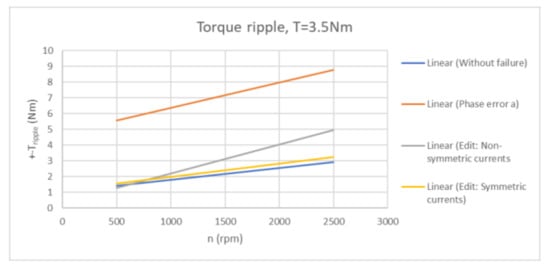
Figure 22.
Torque ripple dependence for constant nominal motor torque.
5. Verification of Measurements
The data of measured currents and voltages using a power five-phase analyzer were recorded during all measurements. These data were then entered into a Matlab environment to test the correctness and efficacy of using new fault-tolerant control in the following manner:
- First, the data from the measured stator currents were entered into Matlab and plotted as a function of time;
- Following that, a five-phase transformation was demonstrated, in which was converted the currents from the abcde system to the stationary reference frame dq;
- Finally, a circle diagram of currents id and iq was created.
In all four cases, the procedure is the same. The distribution of the MMF can be seen using circle diagrams.
5.1. Display of Circle Diagram from Measured Currents for a Normal Operation
This subsection includes a circle diagram of stator currents that depicts the MMF distribution in a five-phase induction motor during normal operation. The procedure is described in the introduction of Section 5. The measurement parameters are 1000 rpm and 3.5 Nm load torque. The measured stator currents are plotted in Matlab in Figure 23a. The dq currents in the stationary reference frame are depicted in Figure 23b, and Figure 23c shows a circle diagram, the dependence of the current id on iq.
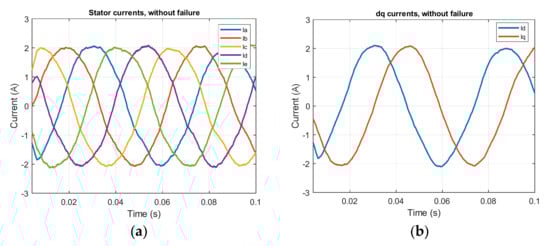
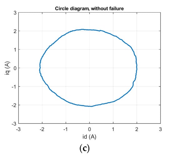
Figure 23.
Measurement for normal operation: (a) stator currents; (b) transformation of measured abcde currents into dq system; (c) circle diagram.
5.2. Display of Circle Diagram from Measured Currents for a One-Phase Fault
A circle diagram of stator currents is shown in this subsection to show the distribution of the MMF in a five-phase induction motor during a one-phase fault. This is the same measurement as in Section 5.1. The measurement parameters, 1000 rpm, and 3.5 Nm are the same as in the previous case.
Figure 24a depicts the measured stator currents in Matlab during a one-phase fault operation. Figure 24b depicts the dq currents of the measured currents, and Figure 24c depicts a circle diagram of the current independence id on iq in a one-phase fault operation.
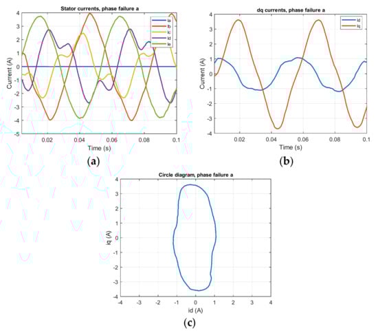
Figure 24.
Measurement for one-phase fault: (a) stator currents; (b) transformation of measured abcde currents into dq system; (c) circle diagram.
This is a nonsinusoidal MMF, as shown in the circle diagram in Figure 24c, because it does not represent a symmetric circle.
5.3. Display of Circle Diagram from Measured Currents for Editing of the Control to Non-Symmetrical Currents
A circle diagram of stator currents is provided in this subsection to show the distribution of the MMF in a five-phase induction motor during control editing to unbalanced currents. The measurement parameters are 1000 rpm and 3.5 Nm, as in the previous case.
Figure 25a depicts the measured stator currents plotted in Matlab. Figure 25b depicts the dq currents of the measured currents, and Figure 25c depicts a circle diagram depicting the dependence of the current id on iq in the editing of control to unbalanced (nonsymmetrical) currents.
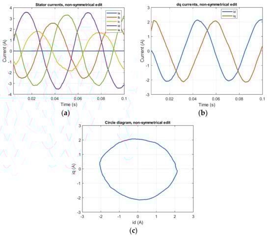
Figure 25.
Measurement for editing of the control to nonsymmetrical currents: (a) stator currents; (b) transformation of measured abcde currents into dq system; (c) circle diagram.
The Figure 25c circle diagram depicts a sinusoidal MMF once again. This indicates that the new fault-tolerant control adjustment for unbalanced currents is accurate. And the motor properties will be better than in a one-phase fault operation with no control editing.
5.4. Display of Circle Diagram from Measured Currents for Editing of the Control to Symmetrical Currents
A circle diagram of stator currents is provided in this subsection to show the distribution of the MMF in a five-phase induction motor during control editing to symmetrical currents. The measurement parameters, 1000 rpm and 3.5 Nm, are the same as in the previous case.
The measured stator currents are plotted in Matlab in Figure 26a. Figure 26b depicts the dq currents, while Figure 26c depicts a circle diagram.

Figure 26.
Measurement for the editing of the control to symmetrical currents: (a) stator currents; (b) transformation of measured abcde currents into dq system; (c) circle diagram.
This is a sinusoidal MMF, as shown in the circle diagram in Figure 26c, confirming once more that the control to symmetrical currents editing is correct.
As seen in these processes, by changing the control, we were able to improve the properties during the failure and move closer to the prefailure state. Section 4 contains the exact results obtained.
Figure 27 depicts the measuring stand where the actual measurements were taken. The Agilent N8900 was used as a DC source between the voltage inverter circuit. The DC link voltage was 510 V. Subsequently, the five-phase induction motor was powered by two three-phase inverters with 5A IGBT transistors from Semikron. Current and voltage waveforms were recorded using a four-channel TEKTRONIX TDS 2024B oscilloscope 200 MHz, 2GS/s. We measured voltages, currents and powers using a Yokogawa wt 1800 precision power analyzer. The torque ripple as well as the direct torque component were measured using a torque sensor with a range of 20 Nm. The engine was loaded with a dynamometer from VUES Brno. The dynamometer motor was a synchronous three-phase motor with a recuperation unit.
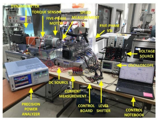
Figure 27.
Measuring station from the measurement of a five-phase induction motor.
Engine control was performed using the Launchpad TMS320f28069 development board from Texas Instrument. The control of the board was implemented using Matlab/Simulink environment.
To measure the stator currents required for control, we created a measuring board, where the current measurement was performed using a LEM current sensor LTS 6 NP. We also used the created board to shift the PWM signals from the 3.3 V control board to 15 V for the inverter.
6. Discussion
This article focused on the control of a five-phase induction motor operating in a one-phase fault. The goal of the article was to present a complete mathematical derivation of modeling a five-phase induction motor in a single-phase fault and its modification, which is presented in Section 2.
Another major goal was to introduce a new, modified fault-tolerant control scheme that can be easily applied to induction motors with any number of phases without requiring any hardware modifications. The entire process of adjusting the control scheme is carried out through software. It also allows for very simple customization for other engines. This is an important aspect of this study. Section 3 describes this control scheme. The control scheme is based on the equations presented in Section 2, and the operation principle is described in detail in the article.
The third goal was to conduct a thorough comparison of the characteristics of the motor in normal operation, one-phase fault operation, and fault-tolerant control modifications when using the new control scheme. We looked at all of the above scenarios to see how much it is possible to improve the motor qualities by changing the control, as opposed to failure without change using the new fault-tolerant scheme. As stated in the article, there are several possible combinations that, when combined with a fault-tolerant control scheme, improve machine characteristics. As a result, we provided two options for modifying the control in the article, as described in Section 3.2.
Section 4 contains detailed measurements of a real five-phase induction motor with a nominal power of 1.1 kW. To begin, motor efficiency was compared in all four states: normal operation, one-phase fault operation, control editing to unbalanced currents, and control editing to symmetrical currents. The measured torque was the rated load torque. According to these courses, the decrease in efficiency at failure compared to normal operation is 22.51%, as shown in Figure 9 This is consistent with the theory that the motor can run with a 20% drop in one-phase failure without editing. Using a fault-tolerant control strategy, we were able to increase engine efficiency. When using unbalanced current control, the reduction was reduced to 15.65% when compared to fault operation. It was only 11.43% when using symmetrical current control. According to the motor efficiency characteristics for reduced load torque, using symmetrical current control provides nearly the same efficiency, as shown in Figure 10 and Figure 11.
Following that, we concentrated on the comparison of input powers, which is critical for the operation of a motor powered by traction batteries. Section 4.2 describes the input power characteristics for all conditions based on mechanical torque and constant engine speed. These waveforms (Figure 12, Figure 13 and Figure 14) show that in the event of a one-phase failure, the nominal torque must be reduced by 22.86% in order to maintain the same input power as in normal operation. We reduced this to 12.86% for unbalanced currents and 8.58% for symmetrical currents by using fault-tolerant control. Because of the power supply system, this measurement must be known. The motor in an EV or HEV is powered by traction batteries, and a failure of one phase would change the amount of power consumed and thus the vehicle range. As a result, the nominal/maximum torque must be reduced.
The following step concentrated on the phase stator currents in all four cases. The currents in the motor will increase during the fault, and their symmetry will be unbalanced. According to the waveforms in Section 4.3 (Figure 15, Figure 16 and Figure 17), the rated motor torque must be reduced by 59.43% in order to maintain the original power load of the motor phases. When using fault-tolerant control on nonsymmetrical currents, they are reduced by 57.15% and symmetrical currents are reduced by 30.85%.
The torque ripple Is a critical factor in electric motors. The sinusoidal MMF has a low torque ripple. However, if there is a failure, the motor ripple is extremely large. In our case, the motor ripple increased from 2 Nm to 8.8 Nm when a fault occurred, as shown in Figure 18 and Figure 19. This equates to a 440% increase. This could have serious consequences for the vehicle’s other systems or mechanical properties, as well as the engine itself. Again, the use of the new fault-tolerant control reduced the size of the ripple, as shown in Figure 20 and Figure 21; for editing unbalanced currents, to 5.6 Nm, and symmetrical currents, to 3.8 Nm.
7. Conclusions
This paper presents an investigation into the possibilities of fault-tolerant control for a five-phase induction motor. The electric motor is now a necessary component of automobile operation. As a result, the motor operation options during a breakdown must be presented. As shown in Section 1, we began this article by presenting current research and findings in the field of control of a five-phase induction motor in a one-phase failure operation.
Mathematical modeling and derivation of a five-phase induction motor are critical for understanding the motor’s overall operation, as well as a failure of one phase and a possible modification. As a result, in the following section, we provided a thorough mathematical derivation of the modeling equations of a five-phase induction machine. This section will help you understand fault-tolerant control for a five-phase induction motor in depth.
The following section of the paper goes over the control strategies used during normal operation measurements. The following describes a new fault-tolerant control technique. The article goes into great detail about how this control method works. This section also includes a thorough mathematical derivation and calculations for fault-tolerant control. The new fault-tolerant control scheme is intended to meet the requirement of any multiphase induction motor for simple control implementation.
After that, we ran a series of tests on a real five-phase induction motor to see how much of an effect using a fault-tolerant control system had on the motor characteristics. Then we compared it to a one-phase fault operating motor that had not been altered in any way. Based on the observed efficiency, power, currents, torques, and torque ripple, we know how to improve and maximize a load of a five-phase induction motor in a single-phase fault, such as in EV or HEV drive operation.
Author Contributions
Conceptualization, J.K.; methodology, S.K.; software, S.K.; validation, Ž.F. and S.K.; formal analysis, J.K. and S.K.; investigation, J.K. and S.K.; resources, Ž.F.; data curation, J.K.; writing—original draft preparation, J.K.; writing—review and editing, S.K.; visualization, Ž.F.; supervision, S.K.; project administration, J.K.; funding acquisition, S.K. All authors have read and agreed to the published version of the manuscript.
Funding
This research was funded by the Slovak VEGA Grant, grant number 1/0085/21 “Research of methods for increasing the efficiency of electric multiphase motor drive systems for automotive applications”.
Acknowledgments
Acknowledgments belong to the University of Zilina, Department of Mechatronics and Electronics, for providing the necessary equipment and funding, as well as the Department of Power Systems and Electric Drives at the University of Žilina, for providing the laboratory with equipment. And UNIZA grand: Research of methods for investigation of operating and fault conditions of drives with multiphase asynchronous motor. Special thanks go to the Technical University of Kosice, Faculty of Electrical Engineering and Informatics for providing a five-phase induction motor.
Conflicts of Interest
The authors declare no conflict of interest.
References
- Alkorta, P.; Barambones, O.; Cortajarena, J.A.; Martija, I.; Maseda, F.J. Effective Position Control for a Three-Phase Motor. Electronics 2020, 9, 241. [Google Scholar] [CrossRef]
- Husain, I.; Ozpineci, B.; Islam, S.; Gurpinar, E.; Su, G.-J.; Yu, W.; Chowdhury, S.; Xue, L.; Rahman, D.; Sahu, R. Electric Drive Technology Trends, Challenges, and Opportunities for Future Electric Vehicles. Proc. IEEE 2021, 109, 1039–1059. [Google Scholar] [CrossRef]
- Bazzi, A.M.; Liu, Y.; Fay, D.S. Electric Machines and Energy Storage: Over a Century of Technologies in Electric and Hybrid Electric Vehicles. IEEE Electrif. Mag. 2018, 6, 49–53. [Google Scholar] [CrossRef]
- Wang, W.; Zhang, J.; Cheng, M.; Li, S. Fault-Tolerant Control of Dual Three-Phase Permanent-Magnet Synchronous Machine Drives Under Open-Phase Faults. IEEE Trans. Power Electron. 2017, 32, 2052–2063. [Google Scholar] [CrossRef]
- Sarwer, Z.; Sartaj, M.; Khan, M.R.; Zaid, M.; Shahajhani, U. Comparative performance study of five-phase induction motor. In Proceedings of the Innovations in Power and Advanced Computing Technologies (i-PACT), Vellore, India, 22–23 March 2019; pp. 1–6. [Google Scholar] [CrossRef]
- Zhao, X.; Song, K.; Zhou, Y.; Cui, T.; Tian, L. Research on fault detection of five-phase fault-tolerant permanent magnet synchronous motor. In Proceedings of the CSAA/IET International Conference on Aircraft Utility Systems (AUS 2020), Online, 18–21 September 2020; pp. 183–188. [Google Scholar] [CrossRef]
- Cao, F.; Lu, H.; Meng, Y.; Gao, D. Sensorless Fault-Tolerant Control of Dual Three-Phase Permanent Magnet Synchronous Motor. World Electr. Veh. J. 2021, 12, 183. [Google Scholar] [CrossRef]
- Li, G.; Zhao, Y.; Li, B. Open-circuit fault-tolerant control of five-phase permanent-magnet synchronous motor using control variable method. In Proceedings of the International Conference on Electrical Machines (ICEM), Gothenburg, Sweden, 23–26 August 2020; pp. 2132–2138. [Google Scholar] [CrossRef]
- Hosseyni, A.; Trabelsi, R.; Mimouni, M.F.; Iqbal, A. Fault tolerant vector controlled five-phase permanent magnet synchronous motor drive with an open phase. In Proceedings of the 15th International Multi-Conference on Systems, Signals & Devices (SSD), Yasmine Hammamet, Tunisia, 19–22 March 2018; pp. 780–784. [Google Scholar] [CrossRef]
- Barrero, F.; Duran, M.J. Recent Advances in the Design, Modeling, and Control of Multiphase Machines—Part I. IEEE Trans. Ind. Electron. 2016, 63, 449–458. [Google Scholar] [CrossRef]
- Kacenka, V.; Rafajdus, P.; Makys, P.; Vavrus, V.; Szabo, L. Static and dynamic fault analysis of Switched Reluctance Motor. In Proceedings of the 2012 ELEKTRO, Rajecke Teplice, Slovakia, 21–22 May 2012; pp. 206–211. [Google Scholar] [CrossRef]
- Kellner, J.; Kaščák, S.; Praženica, M.; Resutík, P. A Comprehensive Investigation of the Properties of a Five-Phase Induction Motor Operating in Hazardous States in Various Connections of Stator Windings. Electronics 2021, 10, 609. [Google Scholar] [CrossRef]
- Kong, J.W.; Wang, K.; Zhang, L.F.; Zhang, J.Y. Fault-tolerant control strategy of five-phase permanent magnet machine based on compensation in third harmonic frame. In Proceedings of the 22nd International Conference on Electrical Machines and Systems (ICEMS), Harbin, China, 11–14 August 2019; pp. 1–5. [Google Scholar] [CrossRef]
- Chikondra, B.; Muduli, U.R.; Behera, R.K. An Improved Open-Phase Fault-Tolerant DTC Technique for Five-Phase Induction Motor Drive Based on Virtual Vectors Assessment. IEEE Trans. Ind. Electron. 2021, 68, 4598–4609. [Google Scholar] [CrossRef]
- Barrero, F.; Bermudez, M.; Duran, M.J.; Salas, P.; Gonzalez-Prieto, I. Assessment of a Universal Reconfiguration-less Control Approach in Open-Phase Fault Operation for Multiphase Drives. Energies 2019, 12, 4698. [Google Scholar] [CrossRef]
- Shin, H.-U.; Baek, S.K.; Lee, K.-B. Fault detection and fault-tolerant operation of a five-phase induction motor driving system. In Proceedings of the IEEE 8th International Power Electronics and Motion Control Conference (IPEMC-ECCE Asia), Hefei, China, 22–26 May 2016; pp. 2487–2492. [Google Scholar] [CrossRef]
- Zhang, C.; Shi, M.; Zhao, H. Fault-tolerant control of five-phase induction motor based on rotor field orientation. In Proceedings of the 4th International Conference on Robotics, Control and Automation Engineering (RCAE), Wuhan, China, 4–6 November 2021; pp. 351–355. [Google Scholar] [CrossRef]
- Zaskalicky, P. Behavior of a five-phase pentacle connected IM operated under one-phase Fault. In Proceedings of the 2019 International Aegean Conference on Electrical Machines and Power Electronics (ACEMP) & 2019 International Conference on Optimization of Electrical and Electronic Equipment (OPTIM), Vilamoura, Portugal, 6–9 September 2019; pp. 126–131. [Google Scholar]
- Zaskalicky, P. Pentagon connected five-phase induction machine working under one-phase fault. In Proceedings of the 2020 IEEE 29th International Symposium on Industrial Electronics (ISIE), Delft, The Netherlands, 17–19 June 2020; pp. 339–344. [Google Scholar] [CrossRef]
- Mohammadpour, A.; Sadeghi, S.; Parsa, L. A Generalized Fault-Tolerant Control Strategy for Five-Phase PM Motor Drives Considering Star, Pentagon, and Pentacle Connections of Stator Windings. IEEE Trans. Ind. Electron. 2014, 61, 63–75. [Google Scholar] [CrossRef]
- Ali, N.; Gao, Q.; Sovicka, P.; Makys, P.; Stulrajter, M.; Ma, K. Power Converter Fault Detection and Isolation using High-Frequency Voltage Injection in Switched Reluctance Motor Drives for Automotive Applications. IEEE J. Emerg. Sel. Top. Power Electron. 2020. [Google Scholar] [CrossRef]
- Jasim, O.; Sumner, M.; Gerada, C.; Arellano-Padilla, J. Development of a new fault-tolerant induction motor control strategy using an enhanced equivalent circuit model. IET Electr. Power Appl. 2011, 5, 618–627. [Google Scholar] [CrossRef]
- Guzman, H.; Duran, M.J.; Barrero, F.; Bogado, B.; Toral, S. Speed Control of Five-Phase Induction Motors With Integrated Open-Phase Fault Operation Using Model-Based Predictive Current Control Techniques. IEEE Trans. Ind. Electron. 2014, 61, 4474–4484. [Google Scholar] [CrossRef]
- Rangari, S.C.; Suryawanshi, H.M.; Renge, M. New Fault-Tolerant Control Strategy of Five-Phase Induction Motor with Four-Phase and Three-Phase Modes of Operation. Electronics 2018, 7, 159. [Google Scholar] [CrossRef]
- Rolak, M.; Che, H.; Malinowski, M. Modelling and fault-tolerant control of 5-phase induction machine. Bull. Pol. Acad. Sci. Tech. Sci. 2015, 63, 997–1006. [Google Scholar] [CrossRef][Green Version]
- Qiu-Liang, H.; Yong, C.; Li, X. Fault-Tolerant Control Strategy for Five-Phase PMSM with Third-Harmonic Current Injection. IEEE Access 2018, 6, 58501–58509. [Google Scholar] [CrossRef]
- Chen, Y.; Liu, B. Design and Analysis of a Five-Phase Fault-Tolerant Permanent Magnet Synchronous Motor for Aerospace Starter-Generator System. IEEE Access 2019, 7, 135040–135049. [Google Scholar] [CrossRef]
- Bhowate, A.; Aware, M.; Sharma, S.; Tatte, Y. Predictive Torque Control for Five Phase Induction Motor Drive with Common Mode Voltage Reduction. In Proceedings of the International Power Electronics Conference (IPEC-Niigata 2018—ECCE Asia), Niigata, Japan, 20–24 May 2018. [Google Scholar] [CrossRef]
- Masoud, M.I. Five phase induction motor: Phase transposition effect with different stator winding connections. In Proceedings of the IECON 2016—42nd Annual Conference of the IEEE Industrial Electronics Society, Florence, Italy, 23–26 October 2016; pp. 1648–1655. [Google Scholar] [CrossRef]
- Zhang, L.; Zhu, X.; Gao, J.; Mao, Y. Design and Analysis of New Five-Phase Flux-Intensifying Fault-Tolerant Interior-Permanent-Magnet Motor for Sensorless Operation. IEEE Trans. Ind. Electron. 2020, 67, 6055–6065. [Google Scholar] [CrossRef]
- Gaikwad, S.A.; Shinde, S.M. Review on five-phase induction motor fed by five-phase voltage source inverter with different conduction mode. In Proceedings of the International Conference on Industry 4.0 Technology (I4Tech), Pune, India, 13–15 February 2020; pp. 199–202. [Google Scholar] [CrossRef]
- Kiran, S.; Aher, A.; Thosar, G. Modeling and Simulation of Five Phase Induction Motor using MATLAB/Simulink. Int. J. Eng. Res. Appl. 2016, 6, 1–8. [Google Scholar]
- Raja, D.; Ravi, G. Design and Implementation of five phase inverter with modified SVPWM switching technique for induction motor drive. In Proceedings of the Fifth International Conference on Science Technology Engineering and Mathematics (ICONSTEM), Chennai, India, 14–15 March 2019; pp. 332–337. [Google Scholar] [CrossRef]
- Che, H.S.; Duran, M.J.; Levi, E.; Jones, M.; Hew, W.P.; Rahim, N.A. Post-fault operation of an asymmetrical six-phase induction machine with single and two isolated neutral points. In Proceedings of the IEEE Energy Conversion Congress and Exposition, Denver, CO, USA, 15–19 September 2013; pp. 1131–1138. [Google Scholar] [CrossRef][Green Version]
- Ahmad, S.; Mishra, A. Mathematical modelling, simulation and control of five-phase induction motor drives. In Proceedings of the International Conference on Emerging Frontiers in Electrical and Electronic Technologies (ICEFEET), Bihar, India, 10–11 July 2020; pp. 1–4. [Google Scholar] [CrossRef]
- Ali, N.; Gao, Q.; Xu, C.; Makys, P.; Stulrajter, M. Fault diagnosis and tolerant control for power converter in SRM drives. J. Eng. 2018, 2018, 546–551. [Google Scholar] [CrossRef]
- Bhowate, A.; Aware, M.V.; Sharma, S. Predictive Torque Control Algorithm for a Five-Phase Induction Motor Drive for Reduced Torque Ripple with Switching Frequency Control. IEEE Trans. Power Electron. 2020, 35, 7282–7294. [Google Scholar] [CrossRef]
Publisher’s Note: MDPI stays neutral with regard to jurisdictional claims in published maps and institutional affiliations. |
© 2022 by the authors. Licensee MDPI, Basel, Switzerland. This article is an open access article distributed under the terms and conditions of the Creative Commons Attribution (CC BY) license (https://creativecommons.org/licenses/by/4.0/).