Abstract
Proton pencil beam scanning is a dynamic beam delivery technique with excellent conformability to the tumor volume. The accuracy of spot size and scanning positions will have a significant effect on the delivered dose distribution. We employed polymer gel dosimeters to measure the spot size and the scanning positions for the Shanghai Advanced Proton Therapy facility (SAPT). Polymer gel dosimeters (MAGAT-f and PAGAT) were utilized to measure the full width at half maximum (FWHM) of the beam spot at various depths on the basis of their MRI readouts. The correlation between the spot FWHM and standard deviation (σ) was analyzed at different depths. The measured Bragg peak range was compared with the Monte Carlo (MC) simulation. Three-dimensional volume rendering of the Bragg peak was reconstructed for the 3D visualization to measure the spot size three-dimensionally. The R2 dose–response curve was investigated with polymer gel dosimeters. The deviations of the Bragg peak ranging between measurement and simulation were 0.13% and −0.53% for MAGAT-f and PAGAT, respectively. Our results ascertain the feasibility of a polymer gel dosimeter to measure the spot size and positions of a proton pencil beam.
1. Introduction
A polymer gel dosimeter acts as a chemical dosimeter that will polymerize after photon or proton irradiation. It principally consists of water, gel, a monomer, a cross-linker, and an oxygen scavenger. After irradiation, water is resolved into free radicals, hydroxide radicals, and hydride radicals. These radicals react with the monomer in the polymer gel, resulting in polymerization. The cross-linker facilitates a chain reaction, resulting in the formation of a cross-linked polymer and a more stable polymer. Polymerization of the gel increases with the irradiation dose. Employing magnetic resonance imaging (MRI) readout [1,2], we can characterize the correlation between polymerization and dose. Polymer gel dosimeter is employed as a relative dose measurement and investigated widely in X-ray irradiation [3,4,5,6]. It was employed for the dose measurement of the scattered proton beams [7,8]. While the use of MAGAT-f and PAGAT gels has been evaluated for photons, thus far its feasibility as a 3D high-resolution range measurement has not been tested for the synchrotron-based proton pencil beam. Compared with the one-dimensional ionization chamber and two-dimensional high-resolution radiochromic film, polymer gel dosimeter possesses the unique potential to measure the three-dimensional dose distribution [9] for clinical investigations.
Pencil beam scanning (PBS) is more conformal to the tumor shape than the conventional scattered beam. However, the spot size and scanning position of the pencil beam must be measured during the quality assurance (QA) procedure [10]. The spot size and the actual scanning positions are of importance for clinical treatment delivery. In this paper, polymer gel dosimeters PAGAT [2,11] and MAGAT-f [12] were used to measure the full width at half maximum (FWHM), scanning positions, and Bragg peak range of the pencil beam.
2. Materials and Methods
2.1. Gel Fabrication
The mass concentration for each gel used in this research is shown in Table 1. All the chemicals were supplied by Sigma-Aldrich. Detailed manufacturing procedure of PAGAT and MAGAT-f gels can be found in [2,11,12].

Table 1.
Mass concentration of each polymer gel dosimeter.
After preparation, the gel was poured into 5 mL glass cuvettes to obtain the dose–response curve. The gel was sealed in the glass cylindrical bottle with diameter of 2.8 cm and height of 12.5 cm for the Bragg peak range measurement. A plastic cylindrical container with a diameter of 7 cm and height of 6.5 cm was used to measure the spot positions. Ten glass cuvettes were employed for analysis of spin–spin relaxation rate (R2) as a function of dose. The bottom thickness of the gel container was 1 mm and made of polystyrene with a density 1.04 g/cm3. The Bragg peak range was calculated, taking into account the water equivalent thickness (WET) [13] of the container.
2.2. Irradiation
SAPT is the first domestically made synchrotron-based facility with a pencil beam scanning system. It can provide 94 energies ranging from 70.6 to 235 MeV. The spot width at ISO-centre ranges from 3.32 to 6.91 mm. In our experiments, five spots were scanned with spacing of 2.818 cm, 20 MU for each spot. Irradiation energy was 73.5 MeV to measure the spot spacing. A cylindrical bottle with diameter 2.8 cm was employed to measure the Bragg peak range of energy 100.2 MeV, 20 MU for the spot. Glass cuvettes were irradiated with proton doses ranging from 0 to 27.6 Gy in a uniform field to obtain the R2 dose–response curve. The spot width of energy 70.6 and 100.2 MeV were 6.68 and 5.33 mm at the ISO-centre. A 2 mm PTW RW3 slab was positioned in front of the gel, and a piece of radiochromic film was attached on the slab to find the spot position because the beam spot at the ISO-centre is not aligned to the laser light during the commissioning stage. The distance between the exit window and the front side of the slab was 0.6 m.
2.3. MRI Scanning
Spin–spin relaxation rate (R2) was used to characterize the dose response of the polymer gel dosimeter. To investigate the relationship between R2 and the absorbed dose, 10 cuvettes were irradiated with protons beams. MR spin echo images to evaluate spin–spin relaxation time T2 (=1/R2) were obtained using a 3.0 T MRI scanner (Achieva TX, Philips Healthcare, Best, The Netherlands) with a head coil. MR images were acquired using a 16-echo multi-spin echo (MSE) sequence. All the scanning was performed 24 h after irradiation. The scanning parameters are shown in Table 2. After obtaining the MR images, 3D Bragg peak was reconstructed with Amira (version 5.4.3, Thermo Fisher Scientific, Waltham, MA, USA) (a software for visualization, processing, and analysis of microscopy images) for the three-dimensional visualization.

Table 2.
MRI scanning parameters.
2.4. Monte Carlo Simulation of SAPT
TOPAS (version 3.1, TOPAS MC Inc., USA) [14] was employed to simulate the Bragg peak of energy 100.2 MeV. Firstly, we modeled the SAPT nozzle with TOPAS, as shown in Figure 1. Virtual source to axis distances (VSADs) from the scanning magnets U and V were 2.87 m and 2.42 m, respectively. The beam monitors were composed of primary and secondary dose monitors and a position monitor. Water equivalent thickness of the three monitors was 1.9 mm. The beam spot was a single Gaussian distribution, and the total particles for each spot was 106. A water cylindrical phantom, which was the same size as the gel container, was employed for scoring. Beam position was set as 287 cm from the ISO-centre. The scoring resolution along the depth direction was 0.1 mm. Interpolation was used when calculating the distal dose falloff (DDF).
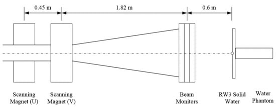
Figure 1.
Simplified SAPT nozzle modeling scheme.
3. Results
3.1. Dose Response of Polymer Gel Dosimeter
The dose–response curve of MAGAT-f gel dosimeter is demonstrated in Figure 2. Obvious saturation was seen at the high-dose region over 20 Gy. Three-order polynomial fitting was used to obtain the calibration curve. Goodness of fit for MAGAT-f gel was 0.9981. The R2 map was converted to the dose map with the R2 dose–response curve.
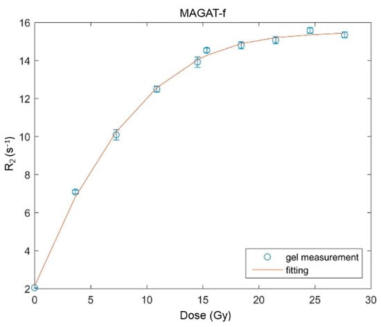
Figure 2.
Dose–response curve of MAGAT-f gel dosimeter.
3.2. Bragg Peak Range
Figure 3a,b demonstrates the polymer gel dosimeter irradiated with a 100.2 MeV proton beam and its MRI readout of different layers. The R2 map was converted to the dose map with the aforementioned R2 dose–response curve. The range measured with two gel dosimeters was compared. The discrepancy between the measurement and Monte Carlo simulation was calculated. The Bragg peak was then reconstructed for 3D visualization.
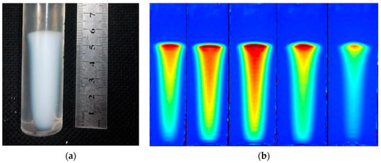
Figure 3.
(a) Irradiated polymer gel dosimeter and (b) five R2 maps of the gel at different planes (100.2 MeV).
Table 3 demonstrates the results of the Bragg peak measured by PAGAT gel, MAGAT-f gel, and MC simulation. Peak is the highest position and Bragg peak range is the depth at the distal 90% dose level. Distal dose falloff (DDF) width is the distance where the dose was reduced from 80 to 20% [10]. It was found that there was a 0.66% variation of Bragg peak range measured with PAGAT and MAGAT-f. The deviations of Bragg peak range between the measurement and MC simulation were 0.13% and −0.53% for MAGAT-f and PAGAT gels, respectively. The DDF discrepancy between the two gels was 5.56%.

Table 3.
Comparison of 100.2 MeV proton Bragg peak between polymer gel dosimeters and MC simulation.
Two perpendicular crossed planes are shown in Figure 4a. We obtained the 3D volume rendering of the Bragg peak for 100.2 MeV measured with PAGAT (Figure 4b–d). After 3D visualization, the spot size at different depths can be measured.
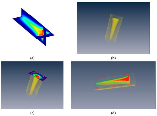
Figure 4.
(a) Two crossed planes of the Bragg peak; (b) reconstructed 3D volume rendering of the Bragg peak; (c) transversal cut; and (d) longitudinal cut of the Bragg peak.
3.3. Beam Spot Analysis
Figure 5a,b are MAGAT-f and PAGAT polymer gels after 73.5 MeV proton irradiation, respectively. The readout of irradiated polymer gel was represented by the volumetric isotropic T2-weighted acquisition (VISTA) map to characterize the beam spot (Figure 5c,d).
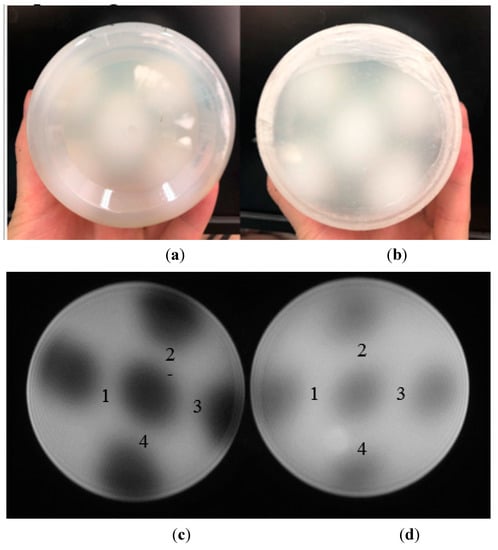
Figure 5.
(a) MAGAT-f gel and (b) PAGAT gel after 73.5 MeV proton irradiation. VISTA map of (c) MAGAT-f and (d) PAGAT gel dosimeter. (No. 1–4 in (c,d) demonstrate the spot spacing numbers measured by MAGAT-f and PAGAT gel dosimeter).
The central spot was chosen to measure the FWHM and standard deviation, σ (Table 4). Horizontal profiles of the central spot measured by MAGAT-f and PAGAT gels were analyzed (Figure 6). Single Gaussian fitting was performed to measure FWHM and standard deviation, as shown in Figure 6c,d. Goodness of fit were 0.9992 and 0.9948 for MAGAT-f and PAGAT, respectively.

Table 4.
Spot width and penumbra width measured with polymer gel dosimeter (73.5 MeV).
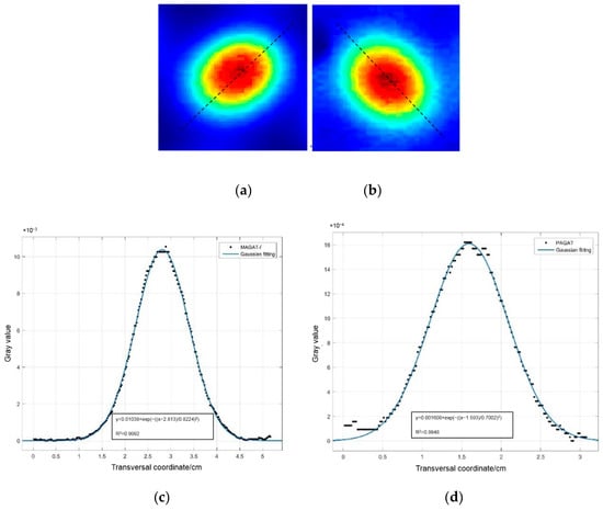
Figure 6.
Proton beam spot measured with (a) MAGAT-f gel (top left) and (b) PAGAT gel (top right); the lateral profile of (c) MAGAT-f gel and (d) PAGAT gel (73.5 MeV).
The spot size of energy 73.5 MeV simulated with the MC method was 5.83 mm. The deviations between the gel measurement and MC simulation were −0.56% and −14.23% for MAGAT-f and PAGAT gels, respectively.
Gaussian fitting results at different planes are shown in Figure 7. Detailed Gaussian fitting parameters are shown in Table 5. With the fitting parameters, the spot width and FWHM can be calculated for the pencil beam. Due to the 3D measurement specificity of polymer gel dosimeters, spot sizes at different depths were acquired (Table 6).
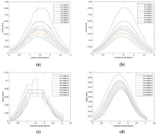
Figure 7.
(a) Dose distribution measured with PAGAT and (b) its Gaussian fitting results of different slices; (c) dose distribution measured with MAGAT-f and (d) its Gaussian fitting results of different slices.

Table 5.
Gaussian fitting results at different depths.

Table 6.
FWHW at different depths measured with PAGAT and MAGAT-f for 73.5 MeV beam.
Figure 8 shows the linear correlation between FWHM and spot width σ at different depths. According to TG-224 [10], FWHM was equal to 2.35σ at a position. The slopes of linear fitting of PAGAT and MAGAT-f were 2.433 and 2.355, respectively. The discrepancies between the fitting slope and the theoretical value were 3.53% and 0.21% for PAGAT and MAGAT-f, respectively.
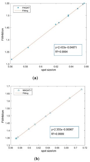
Figure 8.
Correlation between FWHM and spot width measured with (a) PAGAT and (b) MAGAT-f gels.
3.4. Spot Spacing Measurement
In order to compare the actual spot positions with the theoretical value, five spots were scanned (Figure 5). The mass centre of each spot was calculated on the basis of the MRI images with ImageJ (an open-source software for image processing). The distance between two spots (spot spacing) was then calculated according to the centres, and in total, 15 slices were computed (Figure 9). Nos. 1–4 were the distances between two spots labelled in Figure 5. As the gel is a 3D high-resolution dosimeter, we also analyzed the spot spacing at difference depths (depicted as the slice). The spot spacing was set as 2.818 cm in the accelerator control system. The discrepancies between the measurement and the theoretical value were 7.79% and 4.51% for MAGAT-f and PAGAT, respectively.
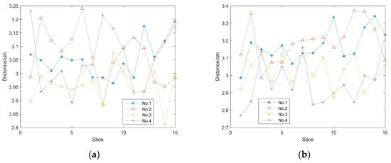
Figure 9.
Spot spacing measured with (a) MAGAT-f gel and (b) PAGAT gel at different depths (slice thickness was 3 mm).
4. Discussion
We utilized two polymer gel dosimeters to measure FWHM, scanning positions, and Bragg peak range of the pencil beam. The deviations of Bragg peak range between the measurement and MC simulation were 0.13% and −0.53% for MAGAT-f and PAGAT gel, respectively. An approximate WET was determined for the container bottom. FWHM at various depths was measured with two polymer gels. As a whole, FWHM tended to increase with the depth within both MAGAT-f and PAGAT measurements. The fluctuation of FWHM at different depths could possibly be attributed to the proton scattering from the solid water slabs positioned at the irradiation path. Drifting protons measured by the beam monitor could be another factor. FWHM of the beam spot was correlated to the standard deviation, but the slope slightly diverged from the expected results. The discrepancies of scanning positions between the measurement and the theoretical value were 7.79% and 4.51% for MAGAT-f and PAGAT, respectively. The position monitor in the nozzle can measure the scanning positions and record them in the machine log file. By analyzing the machine log file recorded by the beam monitor, the position error can vary up to 1 cm because the facility was still under commission. Further studies are needed to measure the spread-out Bragg peak (SOBP) and the dose distribution of real patient plans with polymer gel dosimeter.
Reproductivity of a polymer gel dosimeter can cause errors in the measurement. Vandecasteele et al. [15] investigated the reproducibility of a 3D polymer gel dosimeter (polyacrylamide gelatine gel). A high dosimetric precision (3.1%) was found for the intra-batch study. For the inter-batch experiment, the precision was 4.3%. Deene et al. [16] analyzed the detailed uncertainty of MAGAT and PAGAT gels. The overall accuracy was well within 5% when a careful scanning set-up was designed [16]. In our work, the standard deviation of R2 based on the MRI images ranged from 0.0093 to 0.2778 s−1, peaking at 14.5 Gy. During the experiments, the percentage of gel and the storage and scanning temperature were carefully controlled. The reproductivity was under investigation by fabricating the gel at different batches to obtain the dose response after proton irradiation. Moreover, obvious saturation was found when the dose was over 20 Gy. The percentage of each ingredient of polymer gel was under investigation in order to increase the response sensitivity. There was a 20% underestimation at the Bragg peak measured with a PRESAGE® dosimeter [17]. An empirical-correction-based method was demonstrated for reconciling the LET dependence of Gafchromic EBT film in the proton depth dose curve measurement [18]. Further investigation should be focused on quantifying the effect of LET dependence on the polymer gel dosimeter for appropriate correction.
5. Conclusions
Polymer gel dosimeters PAGAT and MAGAT-f were investigated to measure FWHM, spot width, Bragg peak range, and scanning positions of the pencil beam. The 3D volume rendering of the Bragg peak was reconstructed to measure the spot size at different depths. Obvious saturation was seen at the high dose region over 20 Gy. Bragg peak range and DDF were measured with both gel dosimeters and compared with MC simulation. Our results demonstrated that Bragg peak range errors within 0.5 mm can be achieved with a polymer gel dosimeter. The spot size deviations between the gel measurement and MC simulation were −0.56% and −14.23% for MAGAT-f and PAGAT gels, respectively. The discrepancies between the spot spacing measurement and the theoretical value were 7.79% and 4.51% for MAGAT-f and PAGAT, respectively. The results ascertained the feasibility of the polymer gel dosimeter to measure the spot size, spot positions, and Bragg peak range of the proton pencil beam. In conclusion, polymer gel dosimeter is a valuable tool to investigate the geometric properties of a proton pencil beam with high spatial resolution.
Author Contributions
Data curation, L.Z., M.Z. and X.W.; formal analysis, L.Z. and X.W.; funding acquisition, X.X. and X.W.; investigation, L.Z. and X.X.; methodology, L.Z.; supervision, M.Z., X.X. and X.W.; writing—original draft, L.Z.; writing—review and editing, L.Z. All authors have read and agreed to the published version of the manuscript.
Funding
This research was funded by the National Key R&D Program of China (Ministry of Science and Technology) grant number No. 2016YFC0105406; National Natural Science Foundation of China grant number No. 61571262, No. 11575095, No. 61171115 And The APC was funded by No. 2016YFC0105406.
Institutional Review Board Statement
Not applicable.
Informed Consent Statement
Not applicable.
Data Availability Statement
Data is contained within the article.
Acknowledgments
The authors would like to thank SAPT staff for the experiments support and Stephen Conway for the language corrections.
Conflicts of Interest
The authors declare that there is no conflict of interest.
References
- Hurley, C.; Venning, A.; Baldock, C. A study of a normoxic polymer gel dosimeter comprising methacrylic acid, gelatin and tetrakis (hydroxymethyl) phosphonium chloride (MAGAT). Appl. Radiat. Isot. 2005, 63, 443–456. [Google Scholar] [CrossRef] [PubMed]
- Venning, A.J.; Hill, B.; Brindha, S.; Healy, B.J.; Baldock, C. Investigation of the PAGAT polymer gel dosimeter using magnetic resonance imaging. Phys. Med. Biol. 2005, 50, 3875–3888. [Google Scholar] [CrossRef] [PubMed]
- De Deene, Y.; Hurley, C.; Venning, A.; Vergote, K.; Mather, M.; Healy, B.J.; Baldock, C. A basic study of some normoxic polymer gel dosimeters. Phys. Med. Biol. 2002, 47, 3441–3463. [Google Scholar] [CrossRef]
- De Deene, Y.; Vergote, K.; Claeys, C.; De Wagter, C. The fundamental radiation properties of normoxic polymer gel dosimeters: A comparison between a methacrylic acid based gel and acrylamide based gels. Phys. Med. Biol. 2006, 51, 653–673. [Google Scholar] [CrossRef] [PubMed]
- Baldock, C.; De Deene, Y.; Doran, S.; Ibbott, G.; Jirasek, A.; Lepage, M.; McAuley, K.B.; Oldham, M.; Schreiner, L.J. Polymer gel dosimetry. Phys. Med. Biol. 2010, 55, R1–R63. [Google Scholar] [CrossRef]
- Brown, S.; Venning, A.; De Deene, Y.; Vial, P.; Oliver, L.; Adamovics, J.; Baldock, C. Radiological properties of the PRESAGE and PAGAT polymer dosimeters. Appl. Radiat. Isot. 2008, 66, 1970–1974. [Google Scholar] [CrossRef] [PubMed]
- Avery, S.; Cardin, A.; Lin, L.; Kirk, M.; Kassaee, A.; Maryanski, M.J. 3D dose verification with polymer gel detectors of brain-spine match line for proton pencil beam cranio-spinal: A preliminary study. J. Phys. Conf. Ser. 2015, 573, 012020. [Google Scholar] [CrossRef]
- Avery, S.; Freeman, C.; Shahnazi, K. Initial study of 3D dose verification of multi-field proton therapy treatment along match line with polymer gel detectors. J. Phys. Conf. Ser. 2010, 250, 012033. [Google Scholar] [CrossRef]
- Du, Y.; Wang, X.; Xiang, X.; Wei, Z. Evaluation of hybrid SART + OS + TV iterative reconstruction algorithm for optical-CT gel dosimeter imaging. Phys. Med. Biol. 2016, 61, 8425–8439. [Google Scholar] [CrossRef]
- Arjomandy, B.; Taylor, P.; Ainsley, C.; Safai, S.; Sahoo, N.; Pankuch, M.; Farr, J.B. AAPM task group 224: Comprehensive proton therapy machine qiality assurance. Med. Phys. 2019, 46, 678–705. [Google Scholar] [CrossRef] [PubMed]
- Venning, A.J.; Brindha, S.; Hill, B.; Baldock, C. Preliminary study of a normoxic PAG gel dosimeter with tetrakis (hydroxymethyl) phosphonium chloride as an anti-oxidant. J. Phys. Conf. Ser. 2004, 3, 155–158. [Google Scholar] [CrossRef]
- Aziz, S.A.; Rahman, W.N.; Abdullah, R.; Harun, A.Z.; Zakaria, A. Optimization of Magat with Formaldehyde Gel Dosimeter for Dose Evaluation. In Proceedings of the Global Engineering, Science and Technology Conference, Singapore, 3–4 October 2013. [Google Scholar]
- Zhang, R.; Newhauser, W.D. Calculation of water equivalent thickness of materials of arbitrary density, elemental composition and thickness in proton beam irradiation. Phys. Med. Biol. 2009, 54, 1383–1395. [Google Scholar] [CrossRef] [PubMed]
- Perl, J.; Shin, J.; Schumann, J.; Faddegon, B.; Paganetti, H. TOPAS: An innovative proton Monte Carlo platform for research and clinical applications. Med. Phys. 2012, 39, 9818–9837. [Google Scholar] [CrossRef] [PubMed]
- Vandecasteele, J.; De Deene, Y. On the validity of 3D polymer gel dosimetry: I. reproducibility study. Phys. Med. Biol. 2013, 58, 19–42. [Google Scholar] [CrossRef] [PubMed]
- Deene, Y.D.; Vandecasteele, J. On the reliability of 3D gel dosimetry. J. Phys. Conf. Ser. 2013, 444, 012015. [Google Scholar] [CrossRef]
- Zhao, L.; Newton, J.; Oldham, M.; Das, I.J.; Cheng, C.W.; Adamovics, J. Feasibility of using PRESAGE® for relative 3D dosimetry of small proton fields. Phys. Med. Biol. 2012, 57, N431–N443. [Google Scholar] [CrossRef]
- Zhao, L.; Das, I.J. Gafchromic EBT film dosimetry in proton beams. Phys. Med. Biol. 2010, 55, 291–301. [Google Scholar] [CrossRef]
Publisher’s Note: MDPI stays neutral with regard to jurisdictional claims in published maps and institutional affiliations. |
© 2022 by the authors. Licensee MDPI, Basel, Switzerland. This article is an open access article distributed under the terms and conditions of the Creative Commons Attribution (CC BY) license (https://creativecommons.org/licenses/by/4.0/).