Abstract
This research paper proposes an analytical approach for evaluating electromagnetic scattering from a planar complex object made of a perfect electric conductor, which hosts a double negative metamaterial half-layer on the lit face. The method is based on the physical optics approximation of equivalent sources and works in the framework of the uniform geometrical theory of diffracion, so that the scattered field in the surrounding free space is obtained by adding the reflected contribution and the diffracted one, which is originated by the surface break. The effectiveness of the proposed approach is tested and proved by using a full-wave numerical tool to generate reference values.
1. Introduction
Artificial engineered materials propose new solutions in designing and manufacturing structures with given peculiarities at working frequencies and allow one to overcome the intrinsic limitations of standard materials. Negative real parts of permittivity and permeability, as well as the negative refraction index, define very important artificial materials in this context. They are known as double-negative metamaterials (DNG MTMs), negative index materials (NIMs), left-handed materials (LHMs), or backward (BW) media (information about characteristics and applications, as well as additional references, can be found in [1,2,3,4,5,6]). The above acronyms are associated with the unconventional characteristics, e.g., the mutual position of the electric field, magnetic field and wave vector of a propagating plane wave describe LHMs, and BW is related to the backward propagation with the wave vector antiparallel to the Poynting one. The acronym DNG MTM will be used from this point on to denote this class of artificial materials. From the viewpoint of their fabrication, they can be manufactured by implanting small inclusions in host structures or by adding inhomogeneity to host surfaces [1,2,3,4,5,6].
Studies, as well as communication and space applications, can take benefit from techniques for the evaluation of the electromagnetic scattering from composite structure hosting DNG MTMs. The uniform asymptotic physical optics (UAPO) approach suggests alternative analytical solutions to study scattering problems [7,8,9,10,11,12,13,14]. It has been already applied to DNG MTM structures [7,8,9], and its usefulness has been proved by comparisons with data resulting from well-assessed numerical tools. The approach implements convenient approximations and asymptotic techniques to extract the high-frequency diffraction term from the radiation integral, including electric and magnetic currents as equivalent surface sources. The UAPO diffracted field is always expressed in closed form without requiring the solution of differential/integral equations or the computation of special functions, save for the transition function of the uniform geometrical theory of diffraction (UTD) [15]. The electromagnetic field in the region surrounding the scattering structure is then determined by adding the UAPO diffraction contribution to the geometrical optics (GO) one.
This article refers to the exploitation of the UAPO method to evaluate the diffraction of plane waves from the rectilinear discontinuity of a DNG MTM layer hosted by a planar perfect electric conductor (PEC) support (see Figure 1). As is well known, a PEC is an ideal medium typically adopted to approximate the electromagnetic characteristics of a metal at high frequencies, where the UAPO approach works. Accounting for this, such a particular composite structure can be useful, for example, to modify the scattering response of a metallic body as requested by a smart radio environment. Therefore, the availability of an efficient analytical approach to be used in the design process can be of interest for electromagnetic and communication engineers from the application point of view as well as for researchers and scientists from the theoretical point of view. Analytical and numerical preliminary results were presented in [16], where the ability of the UAPO diffracted field to compensate for the jump of the GO field at the reflection shadow boundary in the upper half-space was demonstrated. The equivalent transmission line (ETL) models were applied to the evaluation of the reflection coefficients associated to the DNG MTM external surface. This step is important not only for determining the GO response of the composite structure, but also for formulating the electric and magnetic PO equivalent surface currents in terms of the incident electric field. Note that the PEC support is not present in the DNG MTM structures considered in [7,8] and, therefore, the evaluation of reflection and transmission coefficients needs a different method.
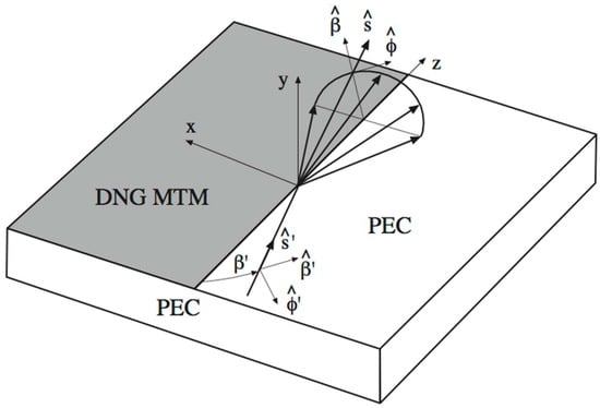
Figure 1.
Useful reference systems for the scattering problem.
The accuracy of the resulting data was not tested in [16], so that an analytical and/or numerical validation is required to complete the study. Accordingly, the importance of this article relies on the numerical validation of the corresponding UAPO solution by means of comparisons with data obtained from the radio frequency (RF) unit of Comsol Multiphysics® (Version 5.6).
2. UAPO Solution for the Diffracted Field
A plane wave propagates in the free space with propagation constant and impinges at the oblique incidence with respect to the discontinuity of a DNG MTM half-layer hosted by the upper surface of an infinite PEC support (see Figure 1). Permittivity , permeability ( are positive numbers and are associated to the free space), and thickness d characterize the DNG MTM half-layer. The unit vector defines the incidence direction.
The UAPO approach provides the following expression for the electric diffracted field at the observation point on Keller’s cone (s denotes the distance from the diffraction point Q to P, , and describes the angular path of P on the half-circumference having center on the discontinuity and radius ) [16]:
The diffraction matrix is formed by the contributions associated to the DNG MTM half-layer and the PEC support. Each diffraction contribution consists of a scalar function and a matrix so given:
The UTD transition function [15] is employed in (2) and (3), whereas the matrices in (4) and (5) are so determined:
The matrices and account for the expressions of the electric and magnetic PO equivalent surface currents on the lit surface of the DNG MTM layer at and contain the reflection coefficients for parallel and perpendicular polarizations. These last ones are evaluated according to the corresponding ETL model [16]. The matrix is equal to and accounts for at the PEC surface.
3. GO Field
According to (1), the UAPO diffracted field is UTD-like and expressed using opportune ray-fixed co-ordinate systems. This last choice also imposes the evaluation of the GO field in the same co-ordinate systems in order to obtain the total field at P by adding GO and UAPO contributions. The following formulations adopt proper transformation matrices to this end.
As regards the incident electric field, it results as
where
Accounting for the knowledge of and , the calculation of the reflected electric field requires two transformation matrices, i.e.,
with
and
4. Tests
The ability of the UAPO diffracted field to compensate for the GO gap at the reflection boundary in the upper half-space was proved in [16]. Accounting for the numerical examples in [16] as preliminary results, Comsol Multiphysics® data are used in this section to test the effectiveness of the above formulations for the evaluation of GO and diffracted fields. The incidence direction is normal to the discontinuity to save computational resources, and the observation domain is a half-circumference with center at the discontinuity, and ( is the free-space wavelength). Save for Figure 6, the following figures contain two plots: (a) amplitude of the total field component evaluated by means of the UAPO-based approach and compared with the corresponding Comsol Multiphysics® data; and (b) comparison between the resultant phase values.
Figure 2, Figure 3, Figure 4, Figure 5 and Figure 6 refer to Case I, which is related to a DNG MTM layer characterized by , , and , whereas Figure 7 and Figure 8 show comparisons concerning Case II, which is identified by a DNG MTM layer with , , and the same thickness of Case I. Case II is presented to assess the approach reliability also when considering magnetic losses.
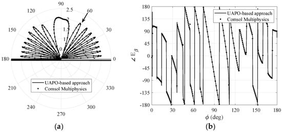
Figure 2.
Case I: comparisons with Comsol Multiphysics® data when , . (a) Amplitude of the total field β–component. (b) Phase of the total field β–component.
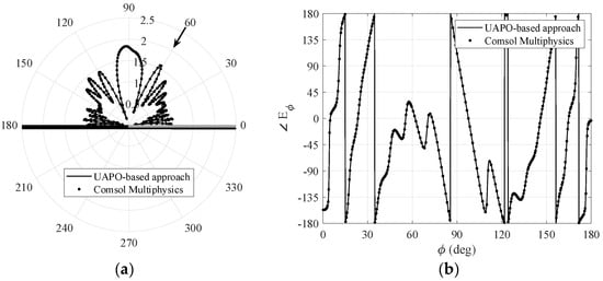
Figure 3.
Case I: comparisons with Comsol Multiphysics® data when , . (a) Amplitude of the total field ϕ–component. (b) Phase of the total field ϕ–component.
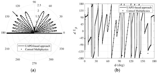
Figure 4.
Case I: comparisons with Comsol Multiphysics® data when , . (a) Amplitude of the total field β–component. (b) Phase of the total field β–component.
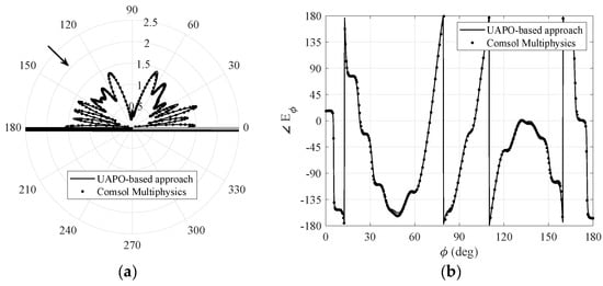
Figure 5.
Case I: comparisons with Comsol Multiphysics® data when , . (a) Amplitude of the total field ϕ–component. (b) Phase of the total field ϕ–component.
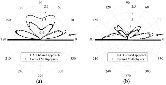
Figure 6.
Case I: comparisons with Comsol Multiphysics® data when . (a) Amplitude of the total field β–component when . (b) Amplitude of the total field ϕ–component when .
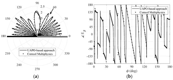
Figure 7.
Case II: comparisons with Comsol Multiphysics® data when , . (a) Amplitude of the total field β–component. (b) Phase of the total field β–component.
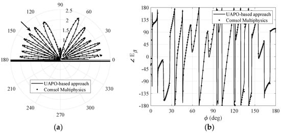
Figure 8.
Case II: comparisons with Comsol Multiphysics® data when , . (a) Amplitude of the total field β–component. (b) Phase of the total field β–component.
Figure 2 and Figure 3 are relevant to and components, respectively, when the incidence direction is in the first quadrant . Since incident, reflected and diffracted fields cooperate to obtain the total field, large oscillations can be observed in the whole observation range, thus producing severe testbeds for the proposed methodology. The interested reader can surely appreciate the excellent agreements in drawing the lobes of the amplitude patterns as well as jumps and arcs of the phase behaviors. Because there is no symmetry of the structure with respect to the yz-plane, it is important to test the performance also when the incidence direction is in the second quadrant. Figure 4 and Figure 5 are relevant to and, despite the fast fluctuations, the data fit together very well, too. On the contrary, the comparisons in Figure 6, which shows the magnitude of and components when the incidence direction is near the grazing condition , are unsatisfactory. According to [9], this result is not surprising since the UAPO approach neglects the surface waves and accounts for the PO limitations.
UAPO performance is well assessed also when considering a DNG MTM layer with electric and magnetic losses as in Case II. Figure 7 and Figure 8 show very good agreements in amplitude and phase of the component when and , respectively, thus confirming the reliability of the proposed method for incidence directions not close to the grazing one. The same comments hold for the component.
5. Discussion and Concluding Remarks
Comsol Multiphysics® data were used as reference values to validate the UAPO approach for solving the electromagnetic scattering from a DNG MTM half-layer hosted by a planar PEC support. Although severe testbeds were considered to establish the reliability of the proposed method, very good results have been obtained when the incidence direction was far from the grazing condition, whereas inaccuracies have been detected when the plane wave direction was close to the lit surface. Moreover, it have been proved that the effectiveness of the UAPO approach is not affected by the permittivity and permeability values of the DNG MTM layer. At last, it is necessary to stress that the UAPO solution works in the UTD context as an approximate PO-based solution, which is easy to apply and does not need solving differential/integral equations or calculating special functions, save for the standard UTD transition function.
Author Contributions
Data curation, F.F.; Methodology, G.R.; Software, G.G., F.F. and R.G.; Supervision, G.R. and C.G.; Validation, G.G., F.F. and R.G.; Writing—original draft, G.R. All authors have read and agreed to the published version of the manuscript.
Funding
This research received no external funding.
Institutional Review Board Statement
Not applicable.
Informed Consent Statement
Not applicable.
Data Availability Statement
Not applicable.
Conflicts of Interest
The authors declare no conflict of interest.
References
- Engheta, N.; Ziolkowski, R.W. (Eds.) Metamaterials: Physics and Engineering Explorations; John Wiley & Sons Inc.: Hoboken, NJ, USA, 2006. [Google Scholar]
- Marquéz, R.; Martin, F.; Sorolla, M. Metamaterials with Negative Parameters: Theory, Design and Microwave Applications; John Wiley & Sons Inc.: Hoboken, NJ, USA, 2008. [Google Scholar]
- Sakoda, K. (Ed.) Electromagnetic Metamaterials: Modern Insights into Macroscopic Electromagnetic Fields; Springer: Berlin/Heidelberg, Germany, 2019. [Google Scholar]
- Bilotti, F.; Sevgi, L. Metamaterials: Definitions, properties, applications, and FDTD-based modeling and simulation. Int. J. RF Microw. Comput. Aided Eng. 2012, 22, 422–438. [Google Scholar] [CrossRef]
- Ji, Y.; Tang, C.; Xie, N.; Chen, J.; Gu, P.; Peng, C.; Liu, B. High-performance metamaterial sensors based on strong coupling between surface plasmon polaritons and magnetic plasmon resonances. Results Phys. 2019, 14, 102397. [Google Scholar] [CrossRef]
- Yan, Z.; Tang, C.; Wu, G.; Tang, Y.; Gu, P.; Chen, J.; Liu, Z.; Huang, Z. Perfect absorption and refractive-index sensing by metasurfaces composed of cross-shaped hole arrays in metal substrate. Nanomaterials 2021, 11, 63. [Google Scholar] [CrossRef] [PubMed]
- Gennarelli, G.; Riccio, G. A UAPO-based solution for the scattering by a lossless double-negative metamaterial slab. Prog. Electromagn. Res. M 2009, 8, 207–220. [Google Scholar] [CrossRef][Green Version]
- Gennarelli, G.; Riccio, G. Diffraction by a lossy double-negative metamaterial layer: A uniform asymptotic solution. Prog. Electromagn. Res. Lett. 2010, 13, 173–180. [Google Scholar] [CrossRef][Green Version]
- Gennarelli, G.; Riccio, G. Diffraction by a planar metamaterial junction with PEC backing. IEEE Trans. Antennas Propag. 2010, 58, 2903–2908. [Google Scholar] [CrossRef]
- Gennarelli, G.; Riccio, G. A uniform asymptotic solution for diffraction by a right-angled dielectric wedge. IEEE Trans. Antennas Propagat. 2011, 59, 898–903. [Google Scholar] [CrossRef]
- Gennarelli, G.; Riccio, G. Diffraction by 90° penetrable wedges with finite conductivity. J. Opt. Soc. Am. A 2014, 31, 21–25. [Google Scholar] [CrossRef] [PubMed]
- Frongillo, M.; Gennarelli, G.; Riccio, G. TD-UAPO diffracted field evaluation for penetrable wedges with acute apex angle. J. Opt. Soc. Am. A 2015, 32, 1271–1275. [Google Scholar] [CrossRef] [PubMed]
- Frongillo, M.; Gennarelli, G.; Riccio, G. Diffraction by a structure composed of metallic and dielectric 90° blocks. IEEE Antennas Wirel. Propag. Lett. 2018, 17, 881–885. [Google Scholar] [CrossRef]
- Frongillo, M.; Gennarelli, G.; Riccio, G. Plane wave diffraction by arbitrary-angled lossless wedges: High-frequency and time-domain solutions. IEEE Trans. Antennas Propag. 2018, 66, 6646–6653. [Google Scholar] [CrossRef]
- Kouyoumjian, R.G.; Pathak, P.H. A uniform geometrical theory of diffraction for an edge in a perfectly conducting surface. Proc. IEEE 1974, 62, 1448–1461. [Google Scholar] [CrossRef]
- Riccio, G.; Gennarelli, G.; Ferrara, F.; Gennarelli, C.; Guerriero, R. Scattering by a metamaterial half-plane on a PEC support. In Proceedings of the XXXIVth URSI General Assembly, Rome, Italy, 28 August–4 September 2021. [Google Scholar] [CrossRef]
Publisher’s Note: MDPI stays neutral with regard to jurisdictional claims in published maps and institutional affiliations. |
© 2022 by the authors. Licensee MDPI, Basel, Switzerland. This article is an open access article distributed under the terms and conditions of the Creative Commons Attribution (CC BY) license (https://creativecommons.org/licenses/by/4.0/).