
An Equivalent Radial Stiffness Method of Laboratory SEPT on Anchorage Performance Prediction of Rockbolts under Different Field Geoconditions


Abstract
:1. Introduction
2. Materials and Methods
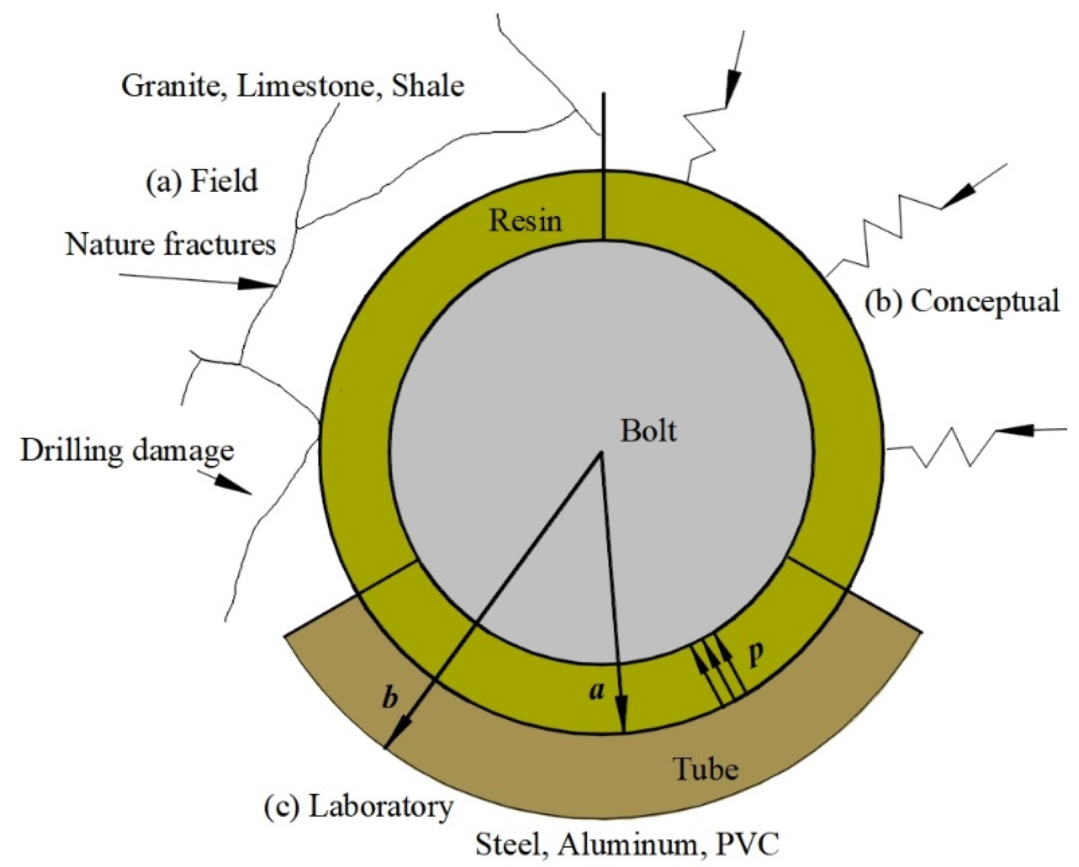
2.1. Equivalent Radial Stiffness Theory
2.2. Equivalent Radial Stiffness Calculation
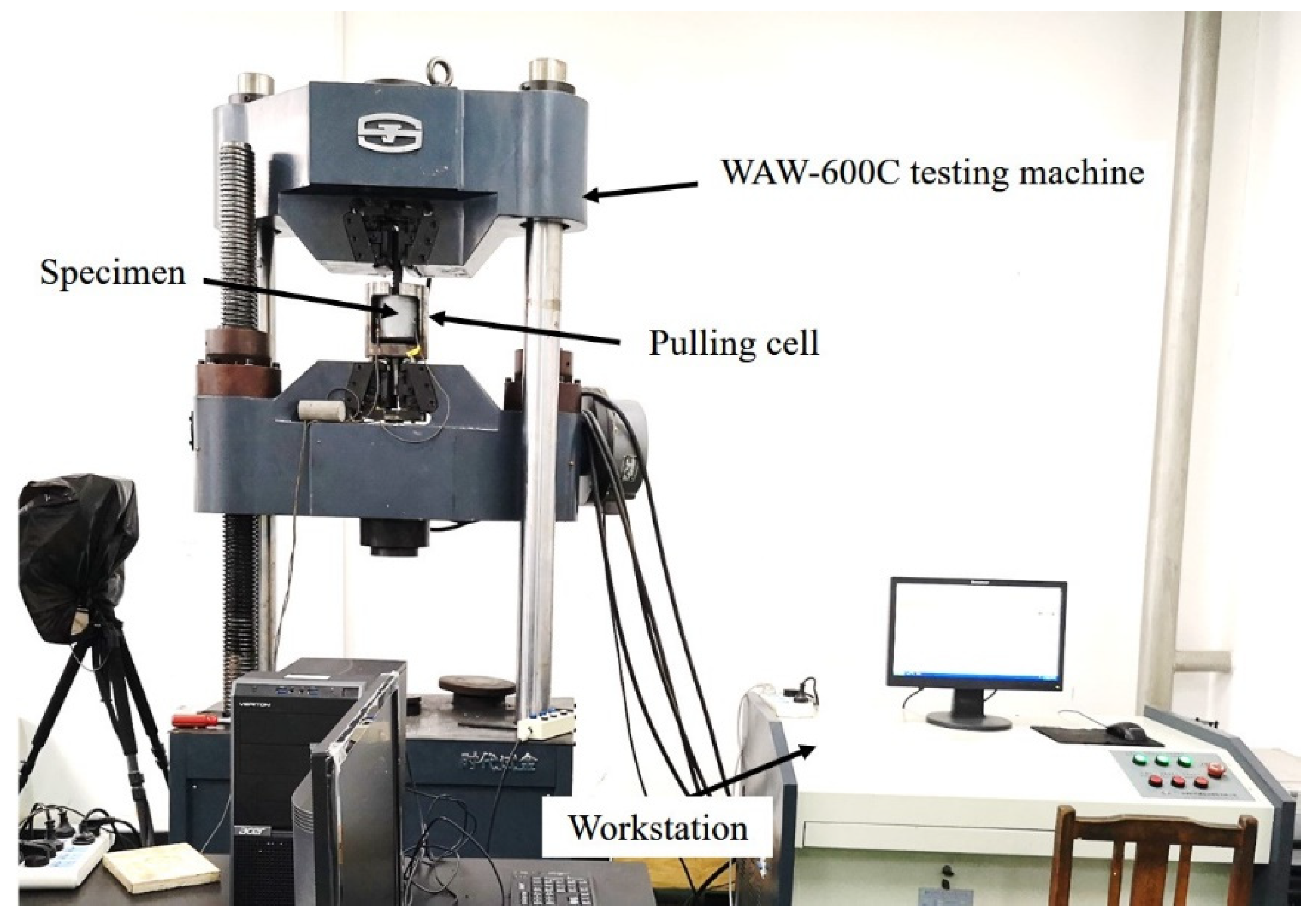
3. Laboratory Configuration
- (1)
- Bolt
- (2)
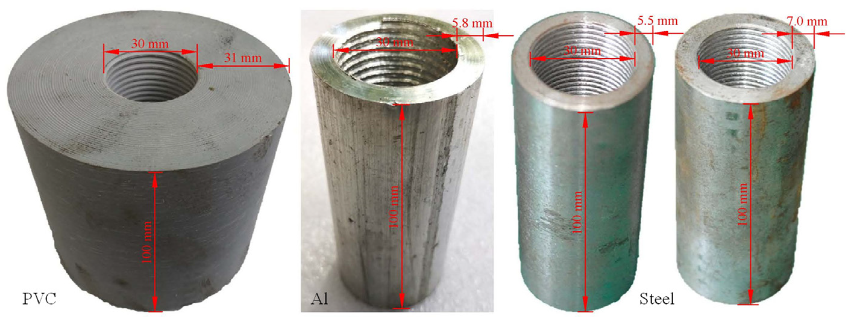
- Confining tubes
- (3)
- Resin anchorage agent
- (4)
- Pull-out specimens
4. Results and Discussion
4.1. Experimental Results
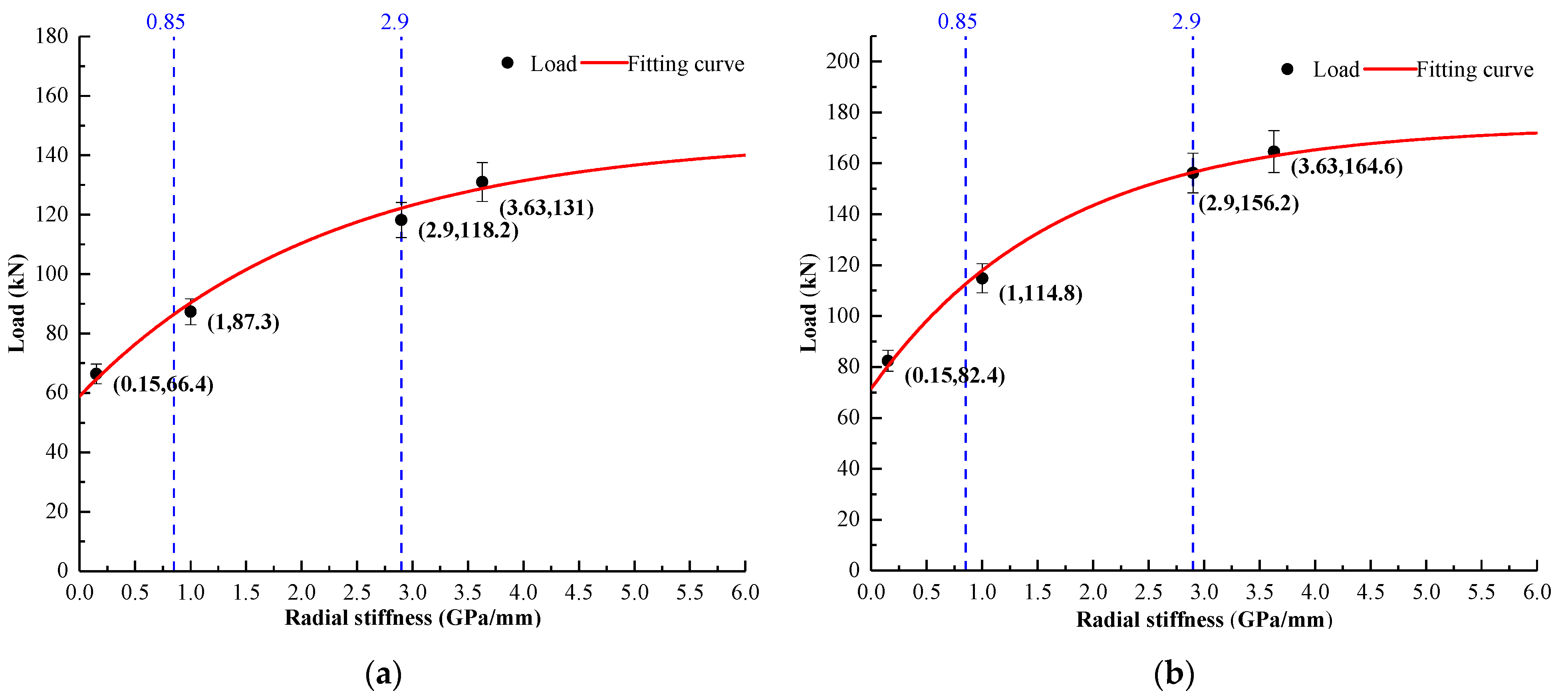
4.2. Anchorage Force vs. Radial Stiffness
4.3. Validity Study of Equation (4)
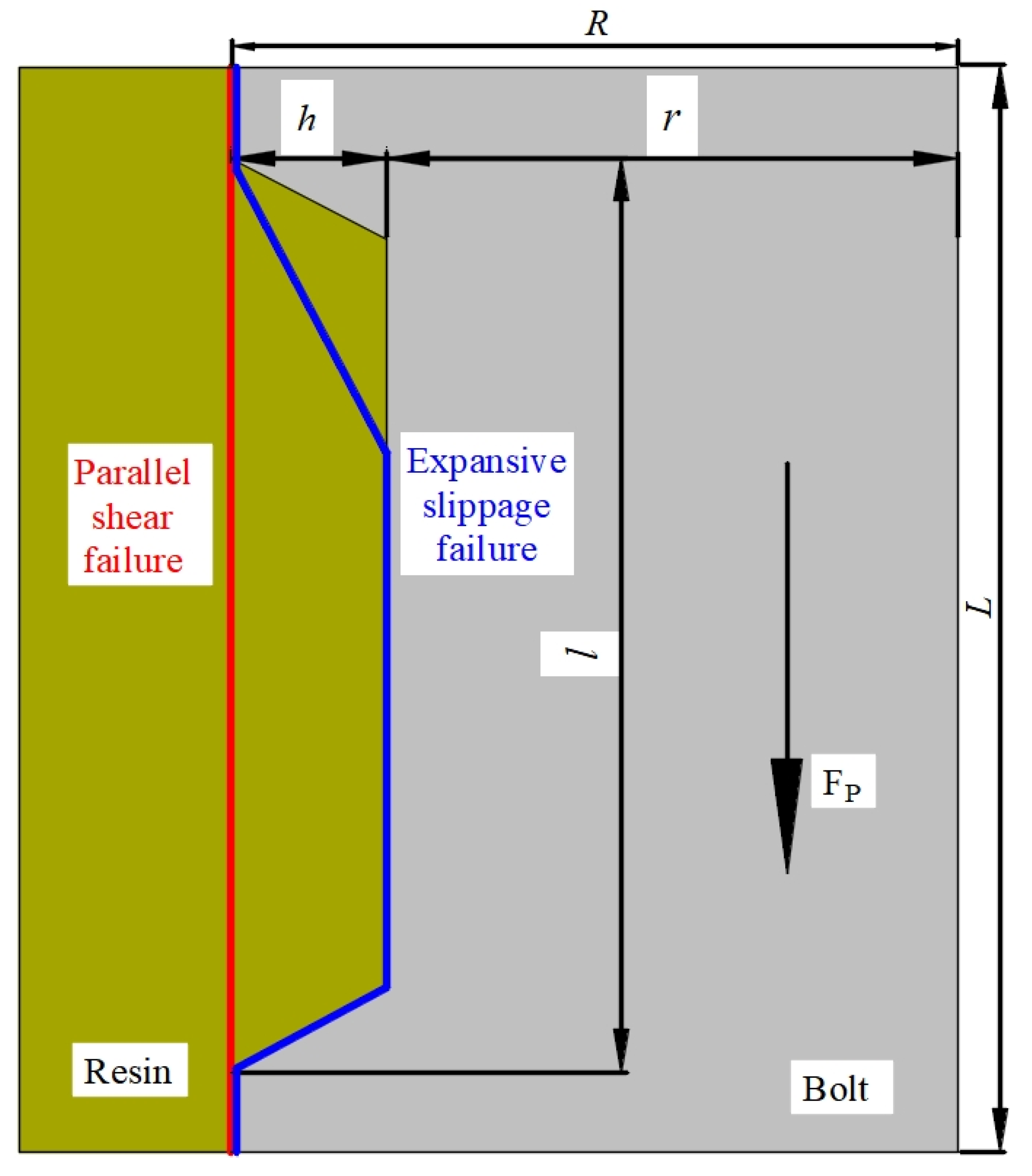
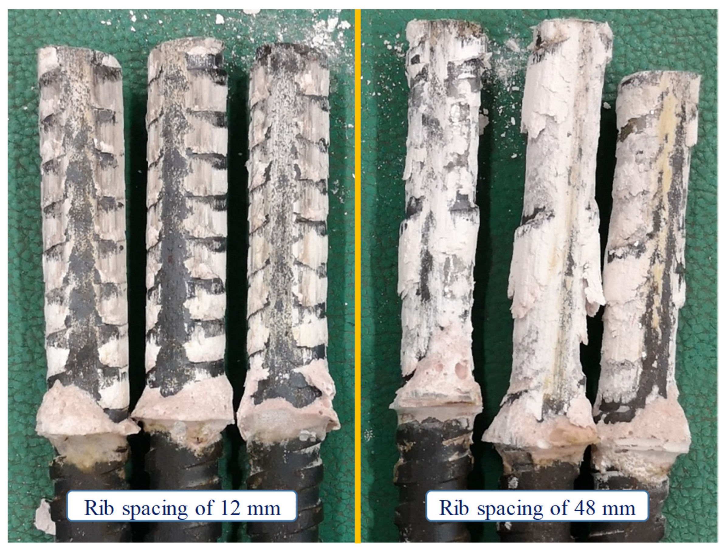
4.4. Failure Mode
5. Conclusions
- (1)
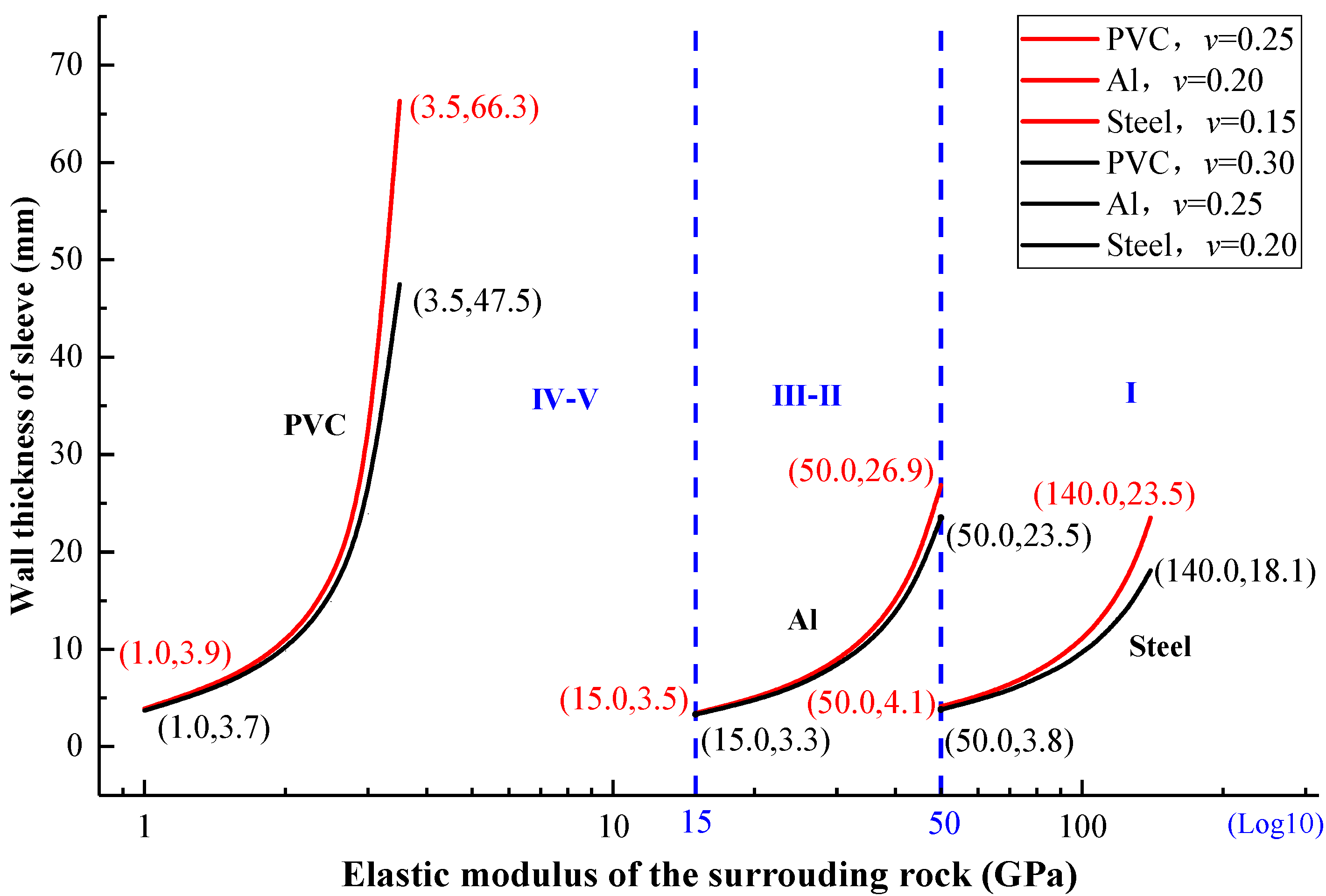
- On the basis of thick wall cylinder theory, an equivalent radial stiffness method was developed to establish the relationship between the confining tube in the laboratory and the elastic properties of surrounding rock (Equations (1)–(3)). Calculation results showed that the PVC tube (E = 4.0 GPa and v = 0.35) corresponds to the radial stiffness of the weak surrounding rock (Er = 1.0–3.5 GPa, vr = 0.25–0.30); Al tube (E = 68.9 GPa and v = 0.33) corresponds to the medium-strong surrounding rock (Er = 15.0–50 GPa, vr = 0.20–0.25); and the steel tube (E = 206 GPa and v = 0.3) corresponds to the strong surrounding rock (Er = 50.0–140.0 GPa, vr = 0.15–0.20). This can be used to improve the accuracy of laboratory SEPT results towards the site outcome (Figure 2).
- (2)
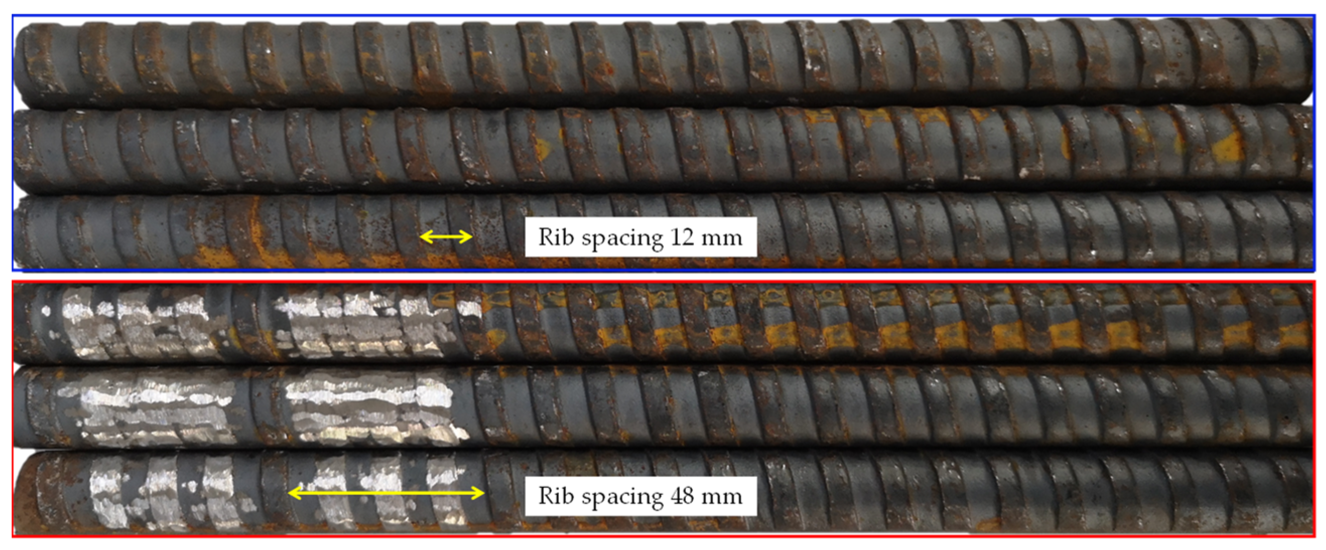
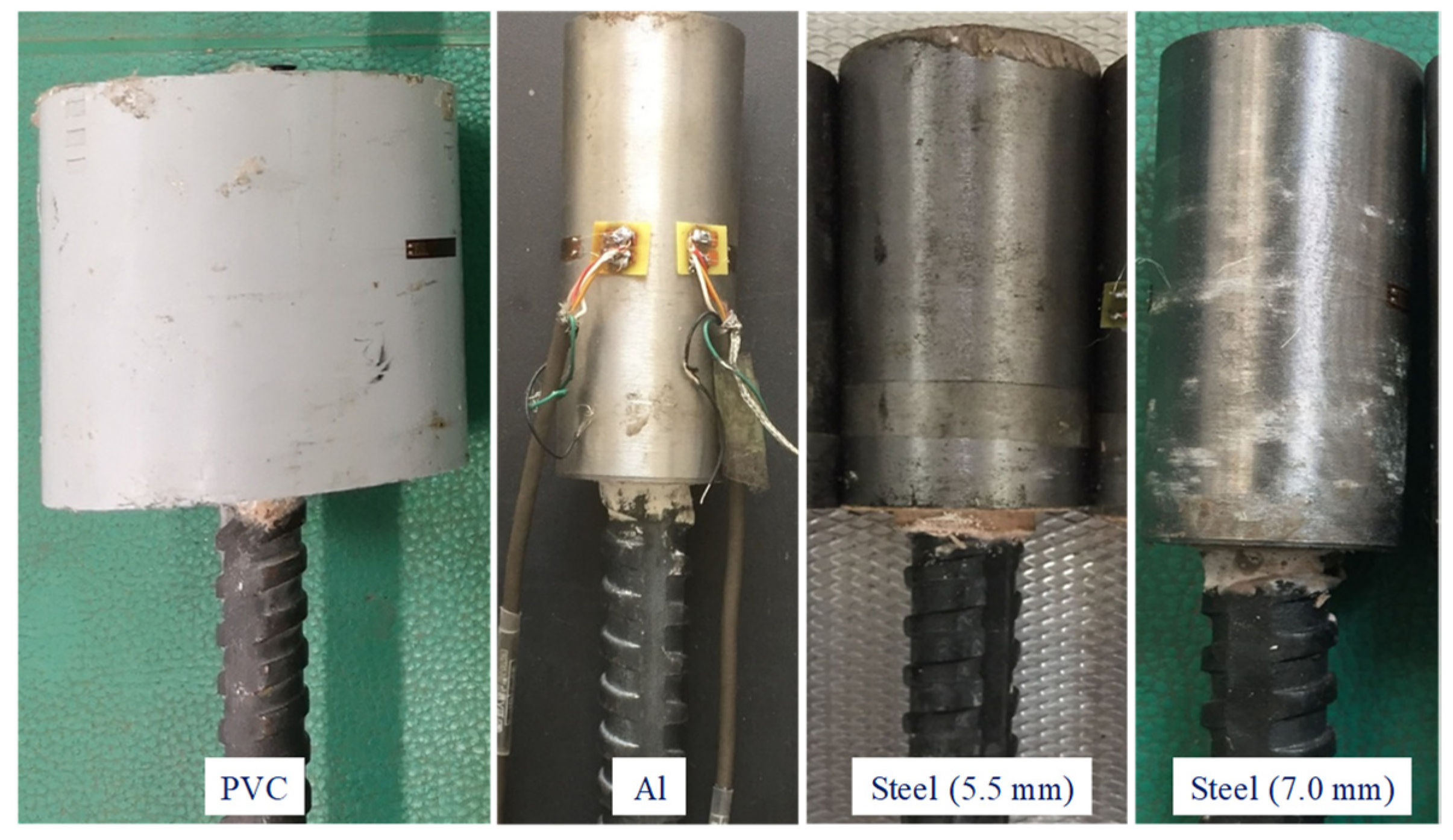
- Two kinds of dextral-threaded bolt were studied using the developed method of this study. PVC, Al, and steel tubes were used as confinement in laboratory SEPT, and anchorage performance was obtained under different surrounding rock strength levels (Figure 7). The results show that axial load capacity increased with the increase in radial stiffness of the confining materials. Compared with PVC tube specimens, peak axial force was nearly double when using thick steel tubes (Table 2).
- (3)
- On the basis of theoretical analysis and curve fitting, the relationship between the average peak axial force and radial stiffness of the confining materials was proposed to be a negative exponential (Equation (4)) function. A validity study was conducted, and its result showed that the proposed relationship agreed well with the theory in the literature. The developed equation could be used to determine the performance of a specific bolt under different field geoconditions and provide accurate parameters for numerical modeling.
- (4)
- Post-testing specimens showed that the failure modes of the original and modified dextral bolts were parallel shear failure and expansive slippage failure, respectively (Figure 10). As anchorage performance is determined by the load-transfer mechanism in a bolting system, which is closely related to the failure model of rockbolting, it may be practical to design and realize different anchorage effects for different field geoconditions via controlling the technology of rockbolting failures, such as with rebar-profile modification.
Author Contributions
Funding
Institutional Review Board Statement
Informed Consent Statement
Data Availability Statement
Conflicts of Interest
References
- Li, C.C. Rockbolting: Principles and Applications, 1st ed.; Butterworth-Heinemann: Oxford, UK, 2017; pp. 1–2. [Google Scholar]
- Małkowski, P.; Niedbalski, Z.; Balarabe, T. A statistical analysis of geomechanical data and its effect on rock mass numerical modeling: A case study. Int. J. Coal Sci. Technol. 2021, 8, 312–323. [Google Scholar] [CrossRef]
- Cao, D.; Wang, A.; Ning, S.; Li, H.; Guo, A.; Chen, L.; Liu, K.; Tan, J.; Zheng, Z. Coalfield structure and structural controls on coal in China. Int. J. Coal Sci. Technol. 2020, 7, 220–239. [Google Scholar] [CrossRef]
- Mao, S. Development of coal geological information technologies in China. Int. J. Coal Sci. Technol. 2020, 7, 320–328. [Google Scholar] [CrossRef]
- Han, J.; Liang, H.; Cao, C.; Bi, Z.Q.; Zhu, Z.J. A mechanical model for sheared joints based on Mohr-Coulomb material properties. Geotech. Lett. 2018, 8, 1–14. [Google Scholar] [CrossRef]
- Kang, H.P. 60 years development and prospects of rock bolting technology for underground coal mine roadways in China. J. China Univ. Min. Techno. 2016, 45, 1071–1081. [Google Scholar]
- Li, C.C.; Stillborg, B. Analytical models for rock bolts. Int. J. Rock Mech Min. 1999, 36, 1013–1029. [Google Scholar] [CrossRef]
- Yuan, G.Y.; Sun, Z.Y.; Li, J.Z. Experimental study on reinforcement effect of bolt support composite members on reinforced mesh. J. China Coal Soci. 2020, 45, 556–567. [Google Scholar]
- Windsor, C.R. Rock reinforcement systems. Int. J. Rock Mech Min. 1997, 34, 919–951. [Google Scholar] [CrossRef]
- Fabjanczyk, M.; Hurt, K.; Hindmarsh, D. Optimization of roof bolt performance. In Proceedings of the International Conference on Geomechanics/Ground Control in Mining and Underground Construction, Wollongong, Australia, 14–17 July 1998; Wollongong of University: Wollongong, Australia, 1998; pp. 413–424. [Google Scholar]
- People’s Republic of China Coal Industry Standards. GB/T35056-2018 Technical Specifications for Rock Bolting in Coal Mine Roadways; China National Coal Association: Beijing, China, 2018. [Google Scholar]
- Kang, H.P.; Cui, Q.L.; Hu, B.; Wu, Z.G. Analysis of anchorage properties and affecting factors of resin bolts. J. China Coal Soci. 2014, 39, 1–10. [Google Scholar]
- Chen, Y.; Li, C.C. Influences of loading condition and rock strength to the performance of rock bolts. Geotech. Test. J. 2015, 38, 208–218. [Google Scholar] [CrossRef]
- Wu, T.; Cao, C.; Han, J.; Ren, T. Effect of bolt rib spacing on load transfer mechanism. Int. J. Min. Sci. Technol. 2017, 27, 431–434. [Google Scholar]
- Xue, D.J.; Zhou, J.; Liu, Y.T.; Gao, L. On the excavation-induced stress drop in damaged coal considering a coupled yield and failure criterion. Int. J. Coal Sci. Technol. 2020, 7, 58–67. [Google Scholar] [CrossRef] [Green Version]
- Xue, D.J.; Liu, Y.T.; Zhou, H.W.; Wang, J.Q.; Liu, J.F.; Zhou, J. Fractal characterization on anisotropy and fractal reconstruction of rough surface of granite under orthogonal shear. Rock Mech Rock Eng. 2020, 53, 1225–1242. [Google Scholar] [CrossRef]
- Zhang, L.; Chen, S.; Zhang, C.; Fang, X.Q.; Li, S. The characterization of bituminous coal microstructure and permeability by liquid nitrogen fracturing based on μCT technology. Fuel 2020, 262, 116635. [Google Scholar] [CrossRef]
- Biumel, M. Performance of grouted bolts in squeezing rock. In Proceedings of the ISRM International Symposium-EUROCK 96, International Society for Rock Mechanics and Rock Engineering, Turin, Italy, 2–5 September 1996; pp. 885–891. [Google Scholar]
- Overwin, U.; Rock, R.; Biumel, M.; Schwab, P. New development for grouted rock bolts. Int. J. Rock Mech Min. Sci. Geomech. Abstr. 1996, 33, 42–48. [Google Scholar]
- Biumel, M.; Schweiger, H.F.; Golser, H. Effect of rib geometry on the mechanical behaviour of grouted rock bolts. In Proceedings of the 23rd General Assembly of the International Tunnelling, Wien, Austria, 12–17 April 1997; pp. 6–7. [Google Scholar]
- Jalalifar, H. A New Approach in Determining the Load Transfer Mechanism in Fully Grouted Bolts. Ph.D. Thesis, University of Wollongong, Wollongong, Australia, 2006. [Google Scholar]
- Aziz, N.; Jalalifar, H.; Concalves, J. Bolt surface configurations and load transfer mechanism. In Proceedings of the 7th Underground Coal Operators Conference, Wollongong, Australia, 6–7 July 2006; pp. 236–244. [Google Scholar]
- Aziz, N.; Jalalifar, H.; Remennikov, A.M.; Sinclair, S.; Green, A. Optimisation of the bolt profile configuration for load transfer enhancement. In Proceedings of the 8th Underground Coal Operators Conference, Wollongong, Australia, 14–15 February 2008; pp. 125–131. [Google Scholar]
- Wu, T.; Cao, C.; Zhao, X.Z.; Zhang, M.; Zhang, H.D.; Ma, S.W.; Han, J. Laboratory study on anchorage performance in different rib spacings of bolt. J. China Coal Soci. 2017, 42, 2545–2553. [Google Scholar]
- Ma, S.; Aziz, N.; Nemcik, J.; Mirzaghorbanali, A. The effects of installation procedure on bond characteristics of fully grouted rock bolts. Geotech. Test. J. 2016, 40, 846–857. [Google Scholar] [CrossRef]
- Feng, X.; Zhang, N.; Yang, S.; He, F. Mechanical response of fully bonded bolts under cyclic load. Int. J. Rock Mech. Min. 2018, 109, 138–154. [Google Scholar] [CrossRef]
- Zhang, M.; Cao, C.; Zhang, H.D.; Tran, V.; Ren, T.; Ma, S.W.; Han, J. Effect of anchoring force by adding steel aggregate in resin anchoring agent. J. China Coal Soci. 2019, 44, 1690–1697. [Google Scholar]
- Zhang, L.; Li, J.H.; Xue, J.H.; Zhang, C. Experimental studies on the changing characteristics of the gas flow capacity on bituminous coal in CO2-ECBM and N2-ECBM. Fuel 2021, 291, 120115. [Google Scholar] [CrossRef]
- Lin, J.; Ren, T.; Cheng, Y.P.; Nemcik, J.; Wang, G.D. Cyclic N2 injection for enhanced coal seam gas recovery: A laboratory study. Energy 2019, 188, 116115. [Google Scholar] [CrossRef]
- Lin, J.; Ren, T.; Wang, G.D.; Booth, P.; Nemcik, J. Experimental investigation of N2 injection to enhance gas drainage in CO2-rich low permeable seam. Fuel 2018, 215, 665–674. [Google Scholar] [CrossRef]
- Chen, B. Stress-induced trend: The clustering feature of coal mine disasters and earthquakes in China. Int. J. Coal Sci. Technol. 2020, 7, 676–692. [Google Scholar] [CrossRef]
- Wu, X.; Peng, Y.; Xu, J.; Yan, Q.; Nie, W.; Zhang, T.T. Experimental study on evolution law for particle breakage during coal and gas outburst. Int. J. Coal Sci. Technol. 2020, 7, 97–106. [Google Scholar] [CrossRef] [Green Version]
- Xue, D.J.; Lu, L.L.; Zhou, J.; Lu, L.; Liu, Y.T. Cluster modeling of the short-range correlation of acoustically emitted scattering signals. Int. J. Coal Sci. Technol. 2020, 1–15. [Google Scholar] [CrossRef]
- Yazici, S.; Kaiser, P.K. Bond strength of grouted cable bolts. Int. J. Rock Mech Min. Sci. Geomech. Abstrs. 1992, 29, 279–292. [Google Scholar] [CrossRef]
- Hyett, A.J.; Bawden, W.F.; Macsporran, G.R.; Moosavi, M. A constitutive law for bond failure of fully-grouted cable bolts using a modified hoek cell. Int. J. Rock Mech Min. Sci. Geomech. Abstrs. 1995, 32, 11–36. [Google Scholar] [CrossRef]
- Zhao, X.Z.; Zhang, H.W.; Cao, C.; Zhang, M.; Zhang, H.D.; Han, J. Optimization of bolt rib spacing and anchoring force under different conditions of surrounding rock. Rock Soil Mech 2018, 39, 1–9. [Google Scholar]
- Hou, C.J. Ground Control of Roadway, 1st ed.; China University of Mining and Technology Press: Xuzhou, China, 2013; pp. 29–33. [Google Scholar]
- Peng, S.S.; Li, H.M.; Zhou, Y. Research on Rock Stratum Control in Shendong and Zhungeer Mining Areas, 1st ed.; Science Press: Beijing, China, 2015; pp. 58–62. [Google Scholar]
- Aziz, N.; Webb, B. Study of load transfer capacity of bolts using short encapsulation push test. In Proceedings of the 22nd International Conference on Ground Control in Mining, US Mine Safety and Health Administration, Morgantown, WV, USA, 5–7 August 2003; pp. 203–207. [Google Scholar]
- People’s Republic of China Coal Industry Standards. GB/MT146.1-2011 Resin Anchor Bolts. Part. 1: Capsules; China National Coal Association: Beijing, China, 2011. [Google Scholar]
- Cao, C.; Ren, T.; Cook, C.; Cao, Y. Analytical approach in optimising selection of rebar bolts in preventing rock bolting failure. Int. J. Rock Mech Min. 2014, 72, 16–25. [Google Scholar] [CrossRef]


| Properties | Values | Properties | Values |
|---|---|---|---|
| Diameter ϕ (mm) | 20.0 | Transverse rib /bottom width (mm) | 4.3/5.6 |
| Transverse rib height h (mm) | 1.8 | Rib spacing L (mm) | 12 or 48 |
| Yielding strength δs (MPa) | 403.1 | Tensile strength σt (MPa) | 567.5 |
| Confinement | Average Anchorage Force (Standard Deviation) (kN) | |
|---|---|---|
| Rib Spacing (12 mm) | Rib Spacing (48 mm) | |
| Steel (7.0) | 131.0 (1.0) | 164.6 (2.7) |
| Steel (5.5) | 118.2 (4.5) | 156.2 (3.3) |
| Al | 87.3 (8.0) | 100.9 (16.1) |
| PVC | 66.4 (3.5) | 82.4 (2.6) |
Publisher’s Note: MDPI stays neutral with regard to jurisdictional claims in published maps and institutional affiliations. |
© 2021 by the authors. Licensee MDPI, Basel, Switzerland. This article is an open access article distributed under the terms and conditions of the Creative Commons Attribution (CC BY) license (https://creativecommons.org/licenses/by/4.0/).
Share and Cite
Zhang, M.; Han, J.; Bi, Z.; Cao, C.; Wu, T.; Ma, S. An Equivalent Radial Stiffness Method of Laboratory SEPT on Anchorage Performance Prediction of Rockbolts under Different Field Geoconditions. Appl. Sci. 2021, 11, 8041. https://doi.org/10.3390/app11178041
Zhang M, Han J, Bi Z, Cao C, Wu T, Ma S. An Equivalent Radial Stiffness Method of Laboratory SEPT on Anchorage Performance Prediction of Rockbolts under Different Field Geoconditions. Applied Sciences. 2021; 11(17):8041. https://doi.org/10.3390/app11178041
Chicago/Turabian StyleZhang, Ming, Jun Han, Zuoqing Bi, Chen Cao, Tao Wu, and Shuangwen Ma. 2021. "An Equivalent Radial Stiffness Method of Laboratory SEPT on Anchorage Performance Prediction of Rockbolts under Different Field Geoconditions" Applied Sciences 11, no. 17: 8041. https://doi.org/10.3390/app11178041
APA StyleZhang, M., Han, J., Bi, Z., Cao, C., Wu, T., & Ma, S. (2021). An Equivalent Radial Stiffness Method of Laboratory SEPT on Anchorage Performance Prediction of Rockbolts under Different Field Geoconditions. Applied Sciences, 11(17), 8041. https://doi.org/10.3390/app11178041