Article

Basalt Textile-Reinforced Vinylester and Epoxy Resins for Anchors Used to Fasten Ventilated Building Facades

by
Tomasz M. Majka
1,*,
Aleksander Byrdy
2 and
Krzysztof Pielichowski
1
1
Department of Chemistry and Technology of Polymers, Faculty of Chemical Engineering and Technology, Cracow University of Technology, ul. Warszawska 24, 31-155 Krakow, Poland
2
Faculty of Civil Engineering, Cracow University of Technology, ul. Warszawska 24, 31-155 Krakow, Poland
*
Author to whom correspondence should be addressed.
Appl. Sci. 2020, 10(19), 6839; https://doi.org/10.3390/app10196839
Submission received: 31 August 2020 / Revised: 23 September 2020 / Accepted: 24 September 2020 / Published: 29 September 2020
(This article belongs to the Special Issue Innovative Textiles in the Era of Circular Economy)

Abstract

:
The aim of this work was to obtain insulation composite anchors based on basalt textile-reinforced vinylester and epoxy resins for fixing heavy building elevation cladding. It concerns the problem of applying materials not originating from wood, construction steel or concrete in the building industry. So far, the application of polymeric materials, including polymeric composites, in construction has been limited to paints, varnishes and glues, and the use of engineering polymers as building materials has been limited. This article presents a study on the influence of the type of basalt reinforcement (in the form of textile, chopped fibre and powder) on the mechanical and functional properties of vinylester and epoxy compositions towards potential applications as construction anchors to fasten building facades. Based on an analysis of the experimental results, a material was selected for the production of novel construction anchors. The results reported here constitute an introduction to further considerations related to the applications of vinylester resin/basalt and epoxy resin/basalt composites as construction materials alternative to commonly used steel and aluminium.

Graphical Abstract

1. Introduction

In the modern building industry, applications of composite materials based on fibre-reinforced resins are gaining scale. As a result of chemical resistance, low heat conductivity, good strength parameters and low production costs, composites are competing with traditional building materials, such as steel and aluminium. Reinforcement bars produced on the basis of epoxy resins and strengthened with basalt fibre or thermal consoles to fix aluminium facade constructions made from epoxy composites strengthened with glass fibre are just examples of such applications.
For that purpose, ceramic–metal composites have been designed and fabricated; as they show low thermal conductivity and high strength [1], they were thus applied for the construction of novel kinds of fasteners. Importantly, they revealed better structure service reliability compared to traditional fasteners [2,3,4].
Another interesting application of composite materials in load-bearing building constructions is epoxy connectors for prefabricated reinforced concrete wall panels connecting reinforced elevation layers separated by a thermal insulation layer with reinforced panel construction layers.
The requirement to reduce heat losses is met through insulating building walls with thicker and thicker thermal insulation layers. Traditional fasteners and consoles made of steel and aluminium pierce the thermal insulation layers and cause intensive thermal bridges. Such thermal bridges may lead to substantial energy losses in the building heating/cooling management. Thus, modern solutions to walls with cladding penetrating the thermal insulation layers seek technologies reducing the energy losses in buildings.
One of such solutions may be application of vinylester and epoxy resins reinforced with basalt textile in the production of anchors dedicated to fixing ventilated facades of buildings since the resins are characterised by incomparably lower heat conductivity than metal anchorage. For example, vinylester resins have coefficients of heat conductivity λ of up to 0.3 W/mK [5], whereas aluminium is around 200 W/mK [6].
Basalt is a natural material from volcanic rocks and, as a powder, is mainly used in construction or high-way engineering. Basalt, after melting at 1300–1700 °C, could be spun into fibres. It can be used as an efficient reinforcement for polymers in the form of powder, fibres, textiles, and wool [7,8,9,10,11]. Thanks to its thermal and sound insulating properties it has been applied in different technical applications, e.g., in automotive, construction and building sectors. The wide range of possible applications results from its advantageous properties. Automobile, aircraft, ship and household appliances are also made with thermosetting resins reinforced with basalt fibres. Possible techniques involve direct pressure autoclaving, laying out, prepregs fabrication, vacuum moulding and winding [12,13,14].
In the building industry, application of materials of low heat conductivity, such as vinylester and epoxy resins, allows substantial reduction in point thermal bridges in ventilated facades or could even eliminate them completely. However, the basic criterion relevant for the material selection for external wall cladding is strength parameters. The anchors of external wall cladding are subject to tensile, compressive and bending stresses under a variety of climate conditions. In the Central European climate, outer walls may face thermal stresses in the temperature range from −25 to 80 °C [15].
This article presents results of investigations on the strength of vinylester and epoxy resins reinforced with basalt textile for the production of insulation construction fasteners as an alternative solution to traditional cladding anchorage of stone external walls. Heavy stone cladding requires an exceptionally dense system of anchors given the necessity of their individual fixing (Figure 1). The original solution proposed in this work on vinylester and epoxy resin-based anchors reinforced with basalt textile could offer substantial energy savings by reducing thermal bridges occurring in insulation layer piercing places that result from the installation of traditional steel anchors in heated buildings.

2. Materials and Methods

2.1. Materials

One of the two main polymeric materials was vinylester resin Polimal® VE-2MM (Ciech, Nowa Sarzyna, Poland), based on bisphenol A, exhibiting a viscosity of 300–400 mPa·s at 25 °C and a gel time (100 g) in the range 15–35 min. According to the producer’s assurance, the resin has an increased resistance to chemical media, atmospheric conditions, water and UV radiation.
A mixture of methyl ethyl ketone and dibutyl phthalate with the trade name Luperox® K-1 (Arkema, Poland) was used as a hardener for the vinylester resin.
The second base resin was epoxy resin Epidian® 652 (Ciech, Nowa Sarzyna, Poland), characterised by an epoxy number of 0.49–0.51 mol/100g, viscosity of 500–900 mPa·s at 25 °C and gel time (100 g) of 25 min.
The hardener applied to the epoxy resin was Mannich base containing phenol, triethylenetetramine with the trade name Hardener TFF (Ciech, Nowa Sarzyna, Poland).
The following materials played the role of fillers:
-
Basalt powder (Table 1) with a grain diameter of 0.08 mm (NB Minerals, Poland);
-
Basalt fibre with a length of 6 mm, diameter of 16 µm and bulk density of 2.6 g/cm3 (Holtex, Poland);
-
Basalt textile with an area density of 235 g/m2 and twill-type weave (Havel, Poland).
Moulds were made of silicone rubber Gumosil® B with catalyst OL-1, (Silikony Polskie, Poland).

2.2. Methods

During the experimental work, measurements were performed of the mechanical and functional properties of the composites produced: vinylester resin/basalt and epoxy resin/basalt. The description of the measurement conditions has been divided into parts related to the mechanical and functional properties.

2.2.1. Mechanical Properties

Static bending resistance tests were conducted using:
-
Static materials testing machine Zwick Roell Z005 (Ulm, Germany), following the norm PN ISO 178, according to which fittings with dimensions 80 × 10 × 4 mm were subjected to a three-point flexural test at 20 °C, 25 °C and 80 °C.
Static tensile strength tests were carried out by means of:
-
Static materials testing machine Zwick 1445 (Ulm, Germany) in accordance with the norm PN-EN ISO 527-2, where 80 × 10 × 4 mm fittings were stretched at −20 °C, 25 °C and 80 °C.
The toughness studies were conducted via the Charpy impact test using a WPM Werkstoffprüfsysteme Leipzig hammer (Markkleeberg, Germany) according to the standard PN-EN ISO 179-1. In the test, fittings with dimensions 100 × 10 × 5 mm and a 2 mm notch experienced dynamic fracture at room temperature.

2.2.2. Functional Properties

Hardness determination was carried out following the Brinnel method by means of a Zwick H04.3106.01 apparatus (Ulm, Germany) in accordance with the norm PN-93/C-89030.02. Fittings with dimensions 80 × 10 × 4 mm were tested at room temperature (25 °C) under a force of 132 N.
Abrasion evaluation was performed through the Schopper method and by means of a Fritz Heckert 08/77 APGi 6/13.10 apparatus (Bielefeld, Germany) equipped with sandpaper NSHa 560 × 670 EB 8 (150). Following the norm PN-69/C-89081, 10 × 10 × 4 mm fittings were subjected to rotational abrasion. Abrasion (X) was then calculated according to Equation (1):
X = m 1 m 2 ρ · L · 1000  
where:
m1—original mass of a sample with a holder (g);
m2—final mass of a sample with a holder (g);
ρ—sample density (g/cm3);
L—abrasion distance (m).

3. Sample Preparation

The vinylester resin/basalt and epoxy resin/basalt composites for the mechanical and functional tests were formed in two ways depending on the filler used.
Fittings containing basalt powder and basalt fibre were obtained by casting at room temperature (25 °C) into silicone moulds, which had been prepared in advance. The percentage share of basalt powder and basalt fibre in the resin composition was always 30% by mass and 20% by mass, respectively. In the case of the vinylester resin, 3% (by mass) of the hardener was added, whereas 40% (by mass) of the hardener was added into the epoxy resin (Figure 2).
Fittings containing basalt textile were produced by continuous pressing at a temperature of 120 °C in a Remi-Plast belt press (Czerwonak, Poland). Exactly 10 layers of basalt textile were supersaturated with resin mixtures (both vinylester and epoxy) with an addition of the hardener. Next, they were subjected to initial pressing for 30 s under pressure of 0.7 Bar followed by proper pressing for 270 s under 6 Bar pressure. In this way, a composite was obtained in the form of sheets, which were then cropped to desired dimensions of 450 × 450 × 5 mm using a Seron 2130 cutter (Stalowa Wola, Poland).
For clarification, Table 2 puts together all the composite designations used by the authors later in this paper.

4. Results and Discussion

The main goal of this study was to confirm the application potential of modern polymeric hybrid materials in the field of building construction, which has been met with little interest so far. This article compares composites based on vinylester resin and epoxy resin strengthened with different types of fillers in terms of not only their properties, but also hardships involved in the production process. Thus, this work highlights the importance of mechanical properties and, secondly, functional properties. Meeting quite high mechanical strength requirements by new generation composite materials raises an interest in testing their application in realistic conditions.

4.1. Mechanical Properties

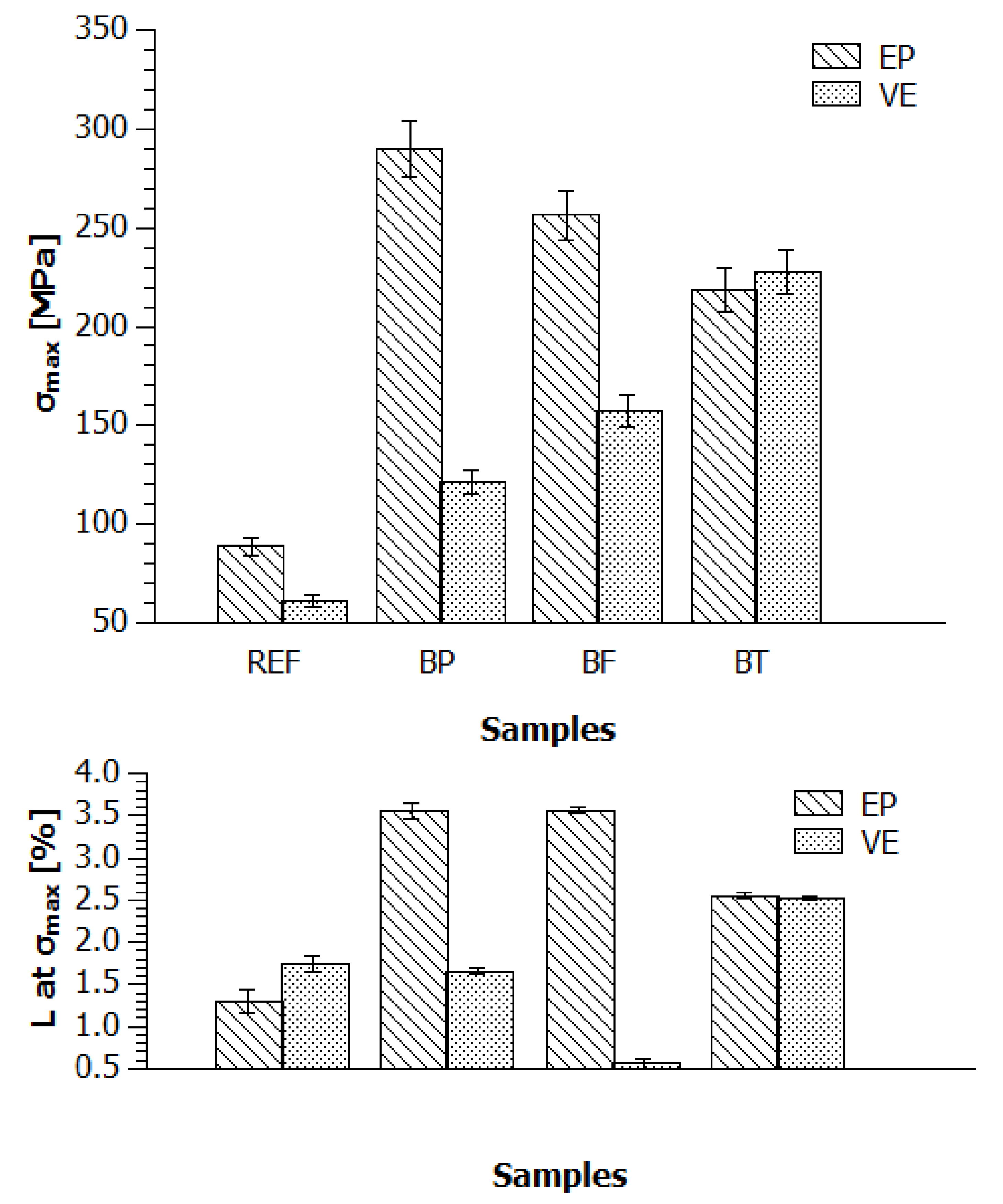
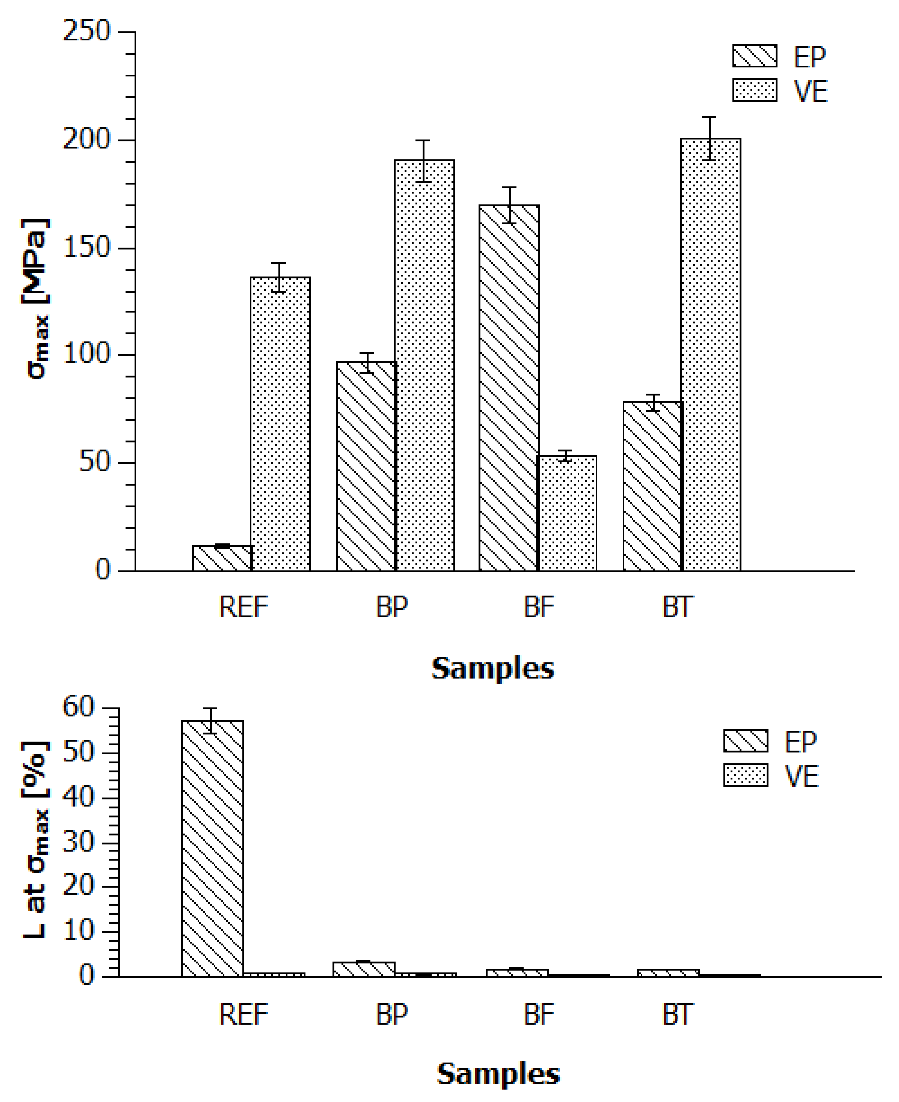
4.1.1. Static Tensile Strength

Figure 3 shows the relation between σmax and the corresponding elongation at the maximum stress point (L at σmax) for the epoxy (EP) and vinylester (VE) composites reinforced with basalt powder (BP), basalt fibre (BF) and basalt textile (BT) for measurements taken at 25 °C.
While stretching a polymeric material, even at room temperature, local temperature spikes by even 20 °C may occur due to some molecular processes of reorganisation and reorientation of the structure. An effect of that may be, for example, mechanical twinning of lattice crystals. The smaller the inclusion particles in the polymeric alloy, the higher the diversity of the samples turns out to be, since smaller particles have a tendency to lump into larger aggregates. Nevertheless, adding such fillers into the highly crystalline matrix results in a lower maximum stress point. It is concluded that despite keeping a constant ratio of unstretched chains to stretched chains in the test, limiting segment motions by introducing reinforcement during the so-called “necking” phenomenon not only reduces the elongation degree, but also flattens the maximum stresses.
The maximum tensile force for the materials based on epoxy resin, as tested at a temperature of 25 °C, was 435 MPa in the case of the reference fittings (Figure 3). The lowest value was recorded for the modifications with basalt powder and fibre, which may be a consequence of weak adhesion of fibre to resin and hence cause easier tensile deformation.
The maximum tensile force in the case of vinylester samples was 235 MPa for the composition modified with basalt fibre (BF). The modification of VE resin with textile did not lead to a drastic improvement of σmax. In this case, the least favourable addition was basalt powder which reduced the maximum tensile force by 45% in the EP matrix and by 38% in the VE matrix. The best tensile strength at 25 °C among the materials studied here was observed for the epoxy resin modified with basalt textile, yet the σmax values of the reference materials (REF) had not been surpassed. As expected, the tensile deformation values at the σmax point were decreasing (for both types of polymeric materials) with an increasing influence on the filling orientation in the matrix. Therefore, the greater the influence on the additive/filler orientation in some resin layer, the lesser the elongation of the composite material. Unfortunately, this trend was not reflected in the σmax values.
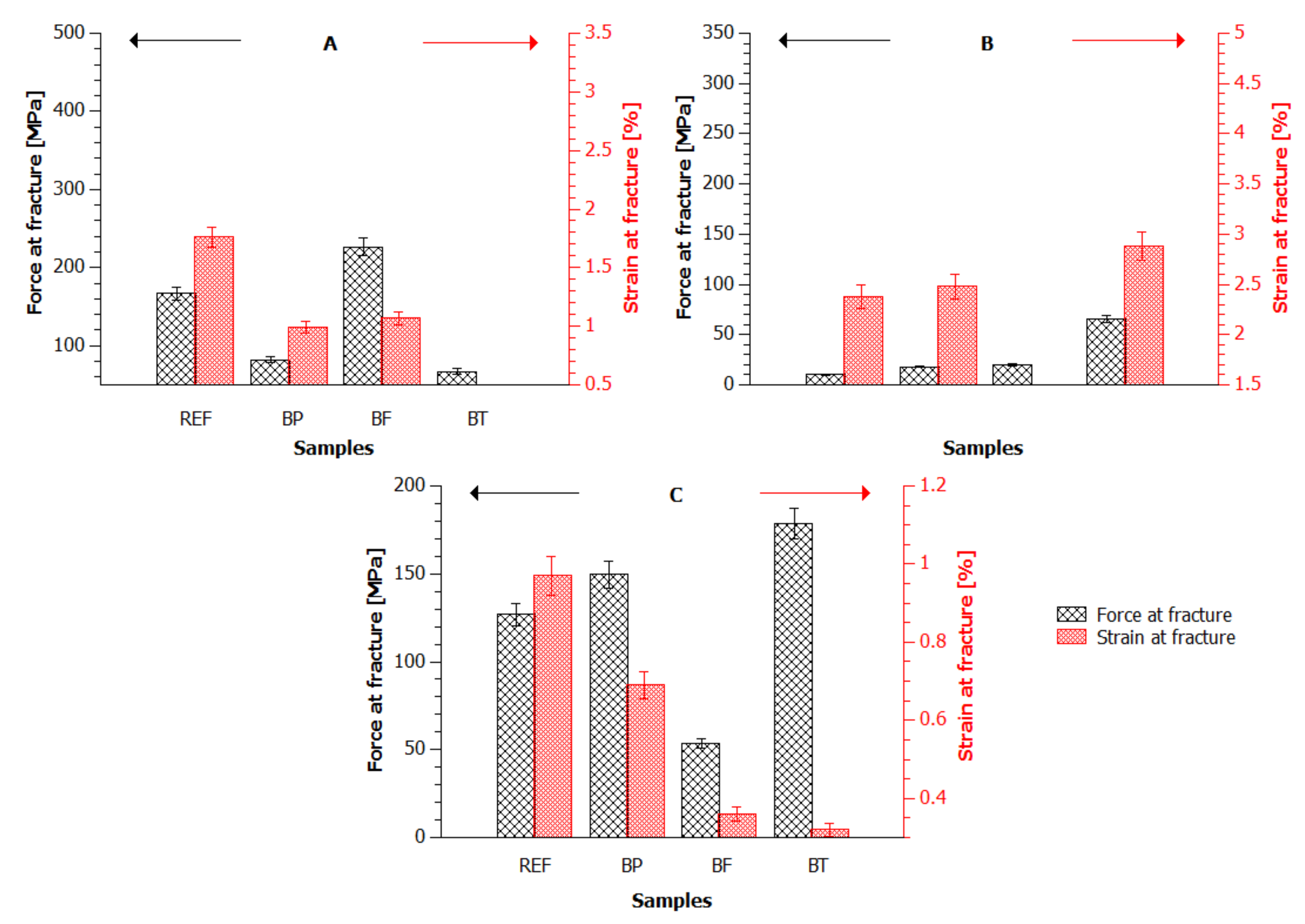
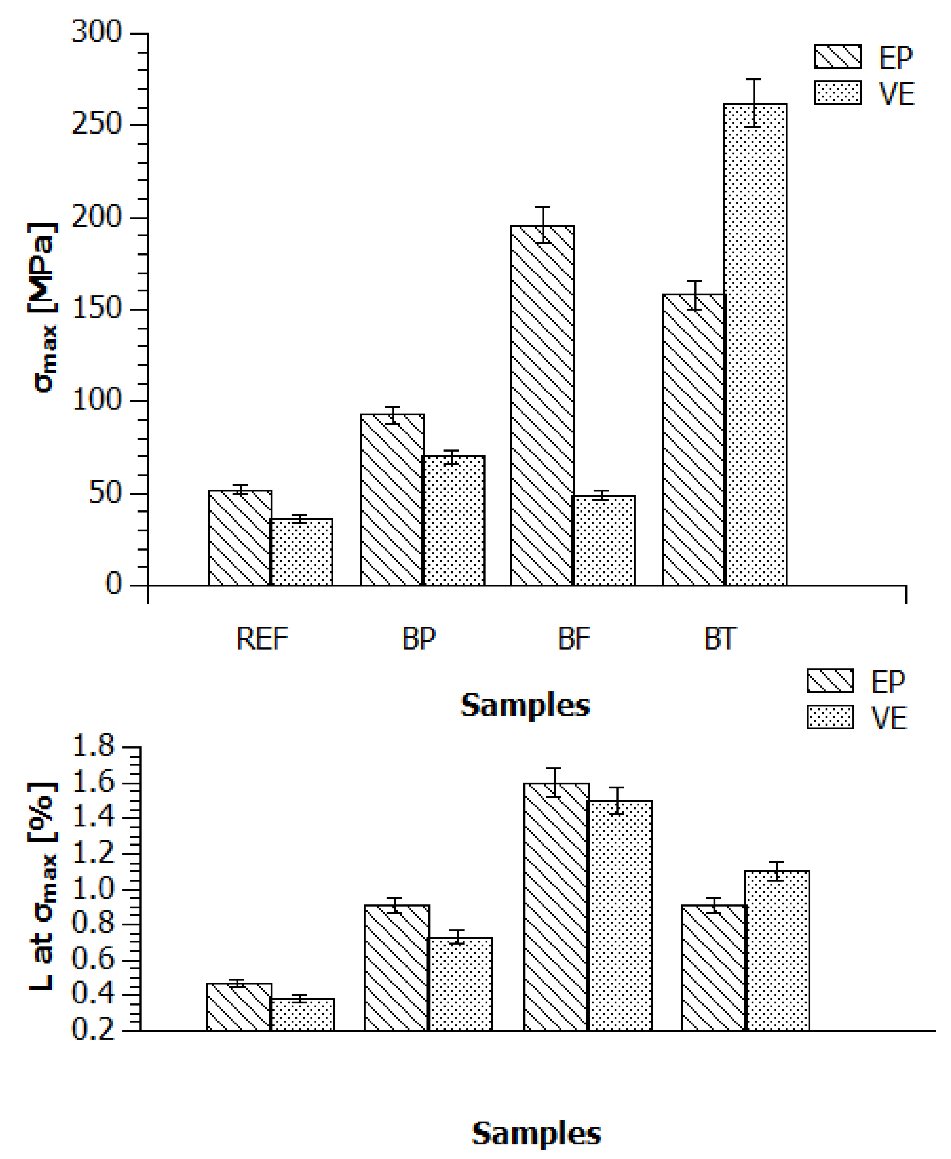
Resin compositions were also tested at temperatures −20 °C and 80 °C. The results of static tensile strength tests at −20 °C reveal that the maximum tensile force (290 MPa) was reached for composition EP/BP (Figure 4). It had been expected that at temperatures below 0 °C the mechanical strength would depend mostly on the strength of the reinforcement itself. Here, the physical and chemical properties of the polymeric matrix and its affinity to the reinforcement played the main role. In both cases, any reinforcement improved the strength properties of the composite with respect to the reference sample. However, only in composite VE, an increase in σmax was observed—VE < VE/BP < VE/BF < VE/BT. In contrast, the EP compositions exhibited the opposite tendency—EP < EP/BP > EP/BF > EP > BT. Worth noticing is the fact that both EP and VE compositions had practically similar σmax values at 20 °C. The elongation of the materials at negative temperatures could have been affected by the affinity of the filling to the matrix, which might have been different in different sample points depending on the varying degree of the additive distribution within the polymer volume. This argument finds confirmation in very similar results for the BT-strengthened compositions at negative temperatures.
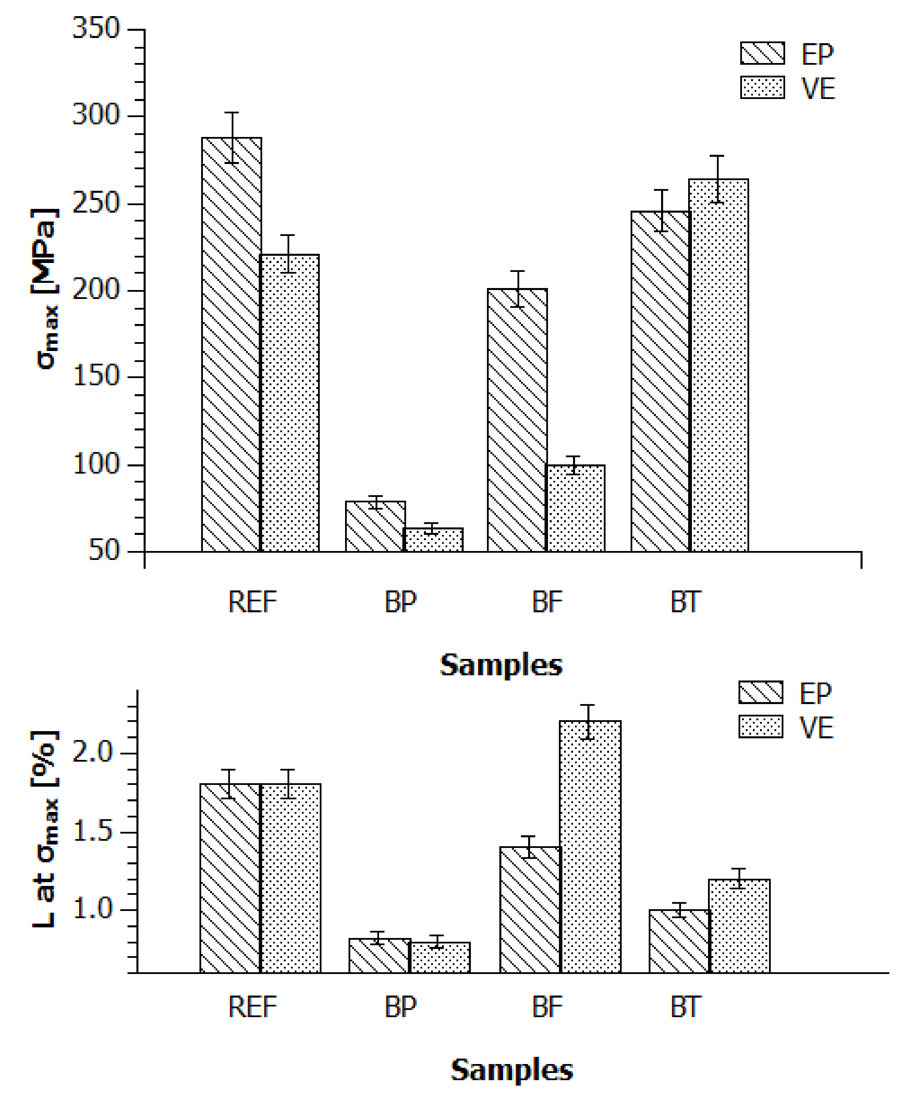
The results presented in Figure 5 confirm high strength parameters of vinylester resin (VE) modified with basalt textile (BT). At a temperature of 80 °C the composites with both epoxy and vinylester resin exhibited a highly elastic or viscoelastic state with clearly dominant viscous properties. This is important since the elasticity moduli for plastics and polymeric materials in the highly elastic state are typically a few orders of magnitude lower than in the forced-elasticity state.
Samples EP/BF, VE/BP and VE/BT were the only samples that preserved their mechanical properties at a higher temperature, which confirms a huge role of matching the reinforcement with a proper matrix. The maximum strength of sample EP/BF of around 180 MPa corresponds to a high elastic state, which may prevent these composites from applications in building constructions exposed to high ambient temperatures. In turn, vinylester materials had better properties at a high temperature. Despite maintaining good strength parameters, the elongation at the σmax point underwent quite a dramatic change. The EP and VE composites became quite stiff and resistant to tensile deformation, which may suggest extra cross-linking of the system at an elevated temperature and an increase in the composition stiffness.
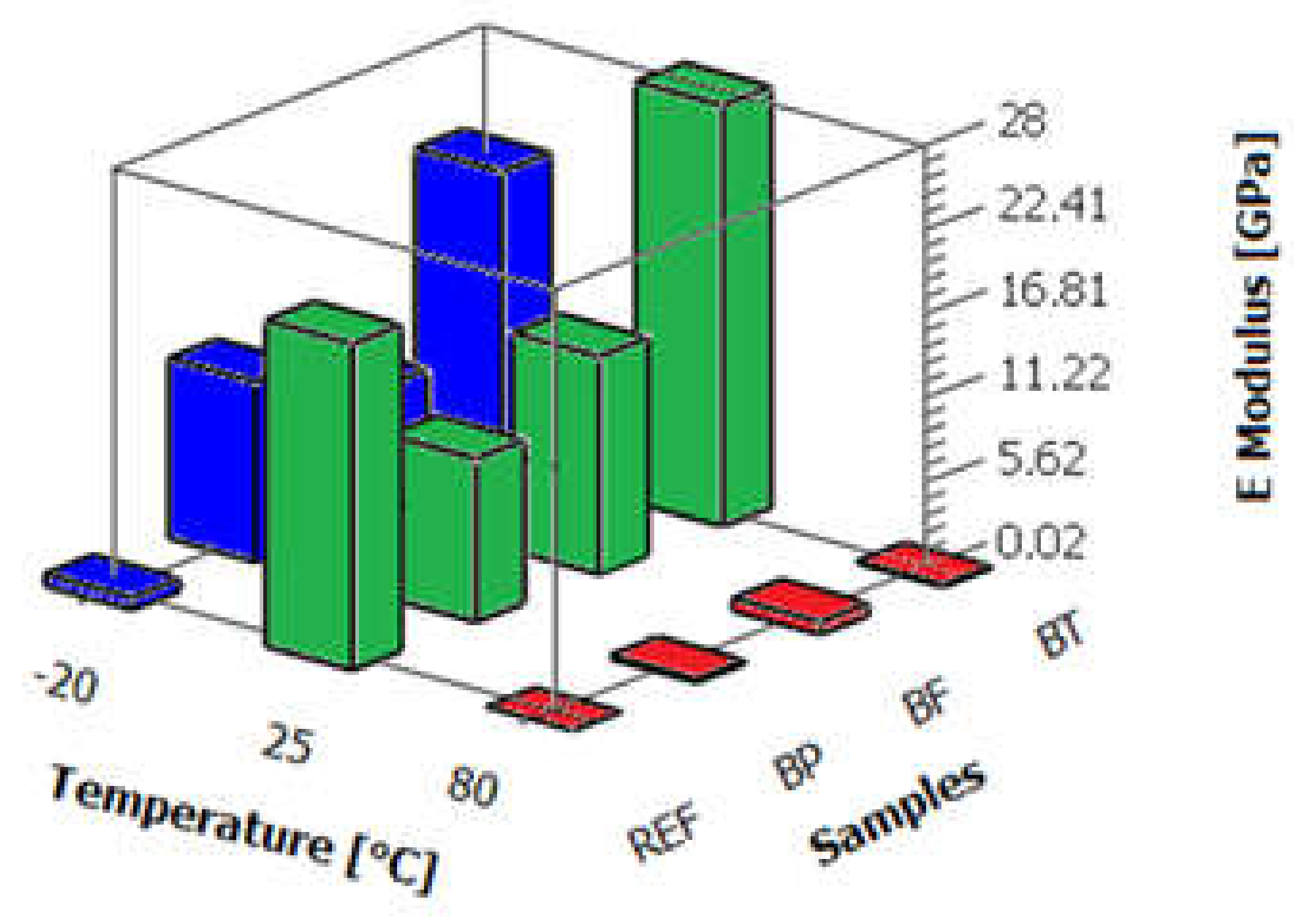
Young’s E modulus (Figure 6) for individual compositions based on epoxy resin reinforcement in the form of basalt fibre—chopped or in the form of textile—at a temperature of 25 °C exceeded multiple times the moduli of the reference samples and those strengthened with basalt powder. The highest modulus was observed for the materials modified with basal textile (~21 GPa). This result suggests that the fibres situated within the resin were very well dampened (fibres supersaturated with resin) and gave the material properties of construction plastics. It should be noted, however, that the elasticity modulus is measured in the initial stage when the sample is still subject to elastic interactions. Reinforcement with fibre oriented both orthotropically in plane and isotropically in space can give an effect of substantial improvement of the mechanical resistance to tension, but this effect is only temporary within the range of weak tensile forces exerted on the composite. This may come as a result of better adhesion of powder to resin or a good strength of the powder itself at that temperature.
The moduli recorded at −20 °C did not exceed 5 GPa in any of the samples tested. At low temperatures, the differences between the results were negligible. In turn, at an elevated temperature, surprisingly, only the EP/BF sample preserved its strength parameters. One may conclude that at a short elongation samples EP and EP/BP, especially in the temperature range 25–80 °C, are particularly prone to deformation in contrast to the fibre-enriched samples.
In the case of Young’s moduli for the vinylester resin-based materials, one may notice that the highest values reached in the experiment were almost three times higher than those observed for the epoxy compositions; the highest value was obtained for the textile-modified (VE/BT) fittings and was 88 MPa at 25 °C.
The distribution trend of the moduli for these materials was very similar to that seen for the epoxy samples. What is worth noticing, though, is the fact that the materials reinforced with powder did not differ from the reference samples in terms of the ratio of the critical stress difference to the corresponding deformations (Figure 7 and Figure 8). What the samples had in common was their similar behaviour pattern within the range of weak forces.
In the case of the series marked in blue in Figure 9, the highest module of ~36 GPa was measured for the VE/BF fitting. The experiment produced atypical results in the case of the other materials, for which the low modulus values may correspond to, among other things, errors of measurements associated with sample contraction or slip in the apparatus clamps. The addition of basalt powder (VE/BP) led to a slight increase in modulus E.
In turn, for samples VE/BF it is possible to see a decrease in the elasticity modulus value only at 25 °C, which again may be connected to weak fibre-to-resin adhesion. In general, all samples containing chopped fibres (BF) may yield barely reproducible results, highly dependent on the method and degree of their homogenisation in the resin. The results show that the composites produced by casting, regardless of the anchorage type, exhibit unstable properties at higher temperatures. Some samples, especially the epoxy ones, reach a highly elastic state at 80 °C. However, in contrast to what was expected, this is not an effect of incomplete material cross-linking, but an intrinsic property of resins (including epoxy resins), which undergo quite rapid plasticisation at an elevated temperature (up to 100 °C).

4.1.2. Static Bending Strength

In Figure 10, a relation is presented of σmax and the corresponding elongation (L at σmax) in the bending strength test for the composites EP and VE reinforced with basalt powder (BP), basalt fibre (BF) and basalt textile (BT) for measurements at 25 °C.
The results indicate, as in Section 4.1.1, that at room temperature reinforcing with basalt powder has a negative effect on the resistance to static bending. Meanwhile, basalt textile provided the resins with the highest σmax value among all the samples that had been reinforced. Both unfortunate and surprising, the result of the reference sample was not outperformed. The amount of fillers (more than 10%) might have been too high and led to a reduction in strength properties since they did not propagate the stresses acting upon them and merely constituted foreign inclusions. The best properties were observed for the materials containing basalt textile. In this case, there were no considerable differences between the epoxy and vinylester resins. Nevertheless, samples VE/BT and EP/BT did not exhibit the greatest elongation degree at σmax. The σmax results at 25 °C are in line with literature reports for materials strengthened with chopped fibre and powder fillers [16,17,18,19,20]. In theoretical considerations described in the literature, the worst strength properties have been seen for composites containing chopped or ground fibre and fibre mats providing the reinforced plastics with both spatial and in-plane isotropy [21,22,23,24,25].
Similarly to the analysis presented for the vinylester compositions at room temperature, decreasing the sample temperature to below 0 °C allowed us not only to preserve the strength properties of the textile-reinforced compositions, but also to slightly improve them, while the error bar values were at a comparable level (Figure 11). Thus, using two in-plane orthotropic textile layers made it possible to preserve the mechanical properties under relatively rigorous measurement conditions. Such an effect was not observed in the case of the powder (BP) or chopped fibre (BF) fillings. This study proved that as far as epoxy resins are concerned the properties of the composites are determined mainly by the filling, and in the case of the vinylester resins, the opposite, by the matrix constituting the dominant composition part.
Raising the ambient temperature to 80 °C during a static bending test trial gave the materials highly elastic properties, with entropic elasticity becoming a dominant feature. Such an elasticity type is associated with much greater deformations exceeding even 100%. The curves showing the relation between the stress and deformation of the material had a non-linear character. The dominant role was mainly played by effects connected to entropic elasticity and viscoelasticity.
The strength results (Figure 12) from the bending tests of epoxy samples (EP) and vinylester samples (VE) at a higher temperature were different. Clearly, the filler type affected the mechanical properties of the epoxy resins, whereas it did not lead to any substantial changes in the case of the vinylester compositions. It is possible to assume that at high temperatures in both matrix types the spatially isotropic filling can definitely be applied as long as the load exerted on the material acts at an elevated temperature.
In the case of the bending strength of the vinylester (VE) composites, one may notice that the filler additives did not have a substantial influence on the strength properties. It is argued here that the application of an additive in the form of fibre, mat or basalt powder does not have a strong impact on the composite strength at an elevated temperature.
The results shown in Figure 13 indicate that the epoxy composites had high Young’s E modulus values at 25 °C. Noticeable is the fact that the composites with unoriented chopped fibres and the composites with powder exhibited very similar modulus values, which was not reflected in the mechanical strength. In the case of the composites with chopped fibre, the filling is oriented parallel, transversely and at an angle α with respect to the load axis. It is worth mentioning that during the bending tests, on one side the material shrank in the direction surface of the cross-section centre, while it slightly stretched on the other side from the centre of the cross section outwards. When the orientation of fibres is perpendicular to the load axis, there is a phenomenon of polymer matrix overload between the transverse fibres. Therefore, in this case, the deformation of the whole composite occurs at the expense of the resin present between the transverse fibres. As a result, the fibres oriented transversely to the force acting upon the sample play a role of foreign inclusions that do not propagate stresses and the composite with a dominant fraction of such fibres is characterised by a lower strength, sometimes even lower than the strength of the reference resin. Such a situation is visible in Figure 10, where the strength of the epoxy composites with chopped fibre and powder turns out to be lower than that of the reference sample. The best properties were observed for the samples containing basalt textile, for which E was 22 GPa.
It should be noticed that in reinforcement with orthotropic textiles the folding of the surface layers depends mostly on the weave type, its density and area density. The basalt textile used in this experiment was a roving type textile with a twill weave, which substantially reduced its surface folding. As a result, under a load parallel to the warp and in the weave nodes, where fibres are oriented transversely, both fibre straightening and tilting in opposite directions could have taken place up to an extent.
Freezing the resin compositions down to a temperature of −20 °C (Figure 13) gave the materials a glassy-brittle physical state where the dominant quality was elasticity, also known as energetic elasticity, given the nature of the molecular processes involved. That is why the curves being monitored during the measurements followed Hooke’s law with a linear relation between specific components of the stress–strain tensor. In the cases observed, an additional reinforcement of the epoxy materials with powder, textile and chopped fibre gave the compositions very high stiffness and the stress increased fast with respect to the material deformation. The mechanical strength doubled as a result of basalt powder application in comparison to the reference sample. The use of a system of fibres oriented isotropically in space allowed us to obtain the highest average values of the fracture stress and thus the bending strength as well. However, as the average values of the fracture stress increased, the standard deviations increased too.
In the tests under a temperature of 80 °C (Figure 13), the highest values of the bending modulus were reached by the materials filled with basalt fibre. However, the results dispersion was very high, which may have been caused by, as mentioned before, the difficulty to obtain reproducible fittings. As can be seen in the figure below, material EP/BT had definitely worse properties in comparison to its performance at room and negative temperatures. What is interesting, Young’s modulus was negligible for the reference materials.
The bending modulus of the modified vinylester resin is presented in Figure 14. Similar to the epoxy resin, at a temperature of 25 °C, the highest value of 18 GPa was observed for the fittings with an addition of basalt textile. A negligible bending modulus was recorded for materials VE/BF. Moreover, a decrease in the modulus was seen for the basalt powder-modified resin.
Filling the vinylester resin with basalt powder particles did not influence the maximum stress value as compared to the reference sample. Nevertheless, the moduli in the initial measurement stage, where the fitting was subjected to elastic deformation forces, were different by about 5000 MPa.
However, reinforcing with basalt mats may not be an efficient solution in elements performing under high temperatures, which is due to a large volume of the vinylester resin between border layers (fabrics). Such a portion of vinylester resin chemically hardened at high temperatures may lose some of the unreacted components, which, while volatilizing, create microcracks/micropores in the composite structure, which then become sample deformation and damage hotbeds in a fitting under a heavy load. The worst situation at high temperatures, though, was observed for the composites reinforced with the non-axially oriented fibres. An increase in the composite temperature leads to a decrease in its viscosity by more intense motions of some polymer chains. Such motions may cause small but quite significant shifts of the reinforcing fibres with respect to the acting load.
Figure 14 presents also the bending modulus for the vinylester composites in the case of measurements taken at 80 °C. The modulus is the highest—16 GPa—for the fittings modified with basalt powder, which is a very high value taking into account the fact that for the best epoxy (EP/BF) sample the modulus was 750 MPa.
Fibre orientation perpendicular to the force and fibre elasticity growth at an elevated temperature could have been among the main causes of the worst measurement results. Chopped fibres under a high temperature might have acted as not only a physical obstacle hindering the deformation of the material, but also as a heat conductor within the sample, leading to its partial degradation and micro-damage to the material structure.

4.1.3. Toughness Tests via Charpy Method

Toughness tests were carried out at 25 °C; five trials per composite type. The trials were conducted in order to check if upon impact there is visually unnoticeable structure delamination weakening the construction and de facto constituting places where further damage may develop, e.g., under moist conditions and subsequent freezing spells at negative temperatures. That is why it is becoming essential to produce composites of high impact resistance and early detection of such damage is important for safe exploitation of building constructions. Every sample experienced fracture upon impact. The failure phenomenon was dependent not only on the impact energy, but also the impactor shape. The speed of the shock wave propagation in the construction material played an important role in the process.
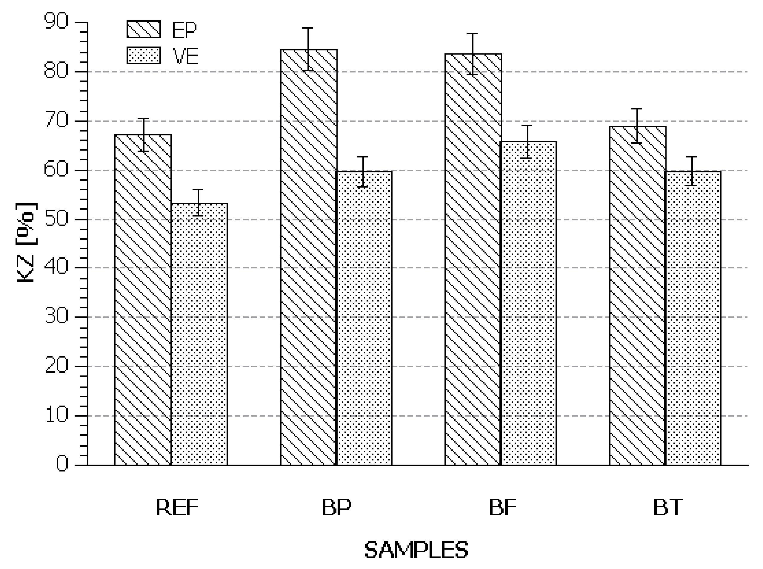
The work needed to tear apart a construction composite depends on the length of fibres, as at the sample fracture time the fibres come out of the sample instead of breaking. Conclusions based on Figure 15 are that the composites modified with fabric (EP/BT and VE/BT) were characterised by the lowest relative toughness values. This suggests that the energy at the fracture moment was a sum of the energy used for the matrix–fibre separation, which meant the destruction of the interface adhesion, the energy used for overcoming friction and pulling the separated fibres out of the matrix and also the energy needed for the crack propagation across the polymeric matrix itself. It is deduced that if the fibres had undergone stretching, the impact energy would have been much greater because the energy used for fibre tensile deformation during impact trials typically exceeds the other energy components.
The highest values of relative toughness were recorded for the chopped fibre-modified composites. However, worth underlining is the fact that in order to achieve much better impact strength of chopped fibre-reinforced composites, one would need to use fibre with a length equal to the so-called critical length of fibre with poor adhesion to the polymeric matrix.
When analysing the results obtained for the resin composites strengthened with chopped fibre (EP/BF and VE/BF), it should be highlighted that impact-induced fracture for such composites was dependent mostly on the content of the fibres, their resistance to tensile deformation, the polymer–fibre interactions and the ductility of the resins. The fracture of the composites containing chopped fibres proceeded in relation to two factors: delamination and fracture of long fibres. The observations and analysis results show that in the first impact destruction phase, there must have been deformations and cracks in the resin. Nevertheless, the final results show that the textile was characterised by a much higher adhesion to the epoxy resin than to the vinylester resin. Next, cracking involved fibres, their sections were broken off and pulled out from the resin. The last stage, like in the case of the textile-modified (BT) composites, was sample destruction. The higher relative toughness values suggest, though, a better ability to absorb energy by the chopped fibres than by basalt textile, which means that the fibres must have been characterised by a lower value of the elasticity modulus than the textile.
The best toughness results were obtained for the epoxy composite strengthened with basalt powder (EP/BP). It turns out that filling with fine particles to a high degree allows not only good adhesion to the polymeric matrix, but most of all better dispersion within the matrix, which was a problem in the case of long and chopped fibres.
For the materials based on vinylester resin, the best toughness was observed for the samples produced with an addition of chopped fibre (VE/BF) because the KZ value in that case exceeded 60%. The epoxy materials with an addition of powder (EP/BP) and chopped fibre (EP/BF) were characterised by values of more than 80%.

4.2. Functional Properties

For the purpose of indirect evaluation of the uniformity of the material obtained, the hardness of all the composites was determined for both sides of the material. In this way, it was possible to acquire information if the reinforcement applied can have an influence on the properties of samples locally, in some direction or within all the composite. The first measurements pointed towards good hardness of the epoxy resin materials.
In Figure 16, it can be seen that the best properties were found for the samples obtained using 30% of the filler in the form of basalt powder, which may be a result of the fact that, despite the moderate hardness of the basalt powder, its value is comparable to that of steel. However, the other side of the components had significantly worse properties. This effect may have been caused by sedimentation of the powder filler during the resin cross-linking process, which in consequence led to formation of a concentrated filler layer on one side of the material. Slightly lower hardness, up to 95 N/mm2, was found for the samples with an addition of basalt fibre. The use of double-sided reinforcement with non-oriented basalt fibres gave materials with similar properties on both sides—possibly as a result of a uniform fibre distribution in the composite. A modification of the epoxy resin with 20% by mass of basalt textiles caused a decrease in the hardness on both sample sides. The cause of this fitting behaviour may be associated with the fact that the fibres have a different area density of particles, spatial compression degree and hardness lower than that of powder. Thus, the high content of fibres in the composite determined such properties of the material.
The hardness of the composites obtained from vinylester resin was comparable to the hardness of the epoxy resin-based composites. The materials enriched with basalt powder and textile had similar hardness values (Figure 16). In this case, there were no substantial differences between the two composite sides, suggesting better reproducibility of the materials.
Worth noticing is the fact that the error bars in Figure 17 are a little larger than the ones presented in Figure 16. This situation confirms also worse reproducibility of the results when using the vinylester resin. This effect may be related to the density of the compositions (resin + hardener + reinforcing filling) at the time of fitting formation and their changes during cross-linking. The density of the vinylester mixes was lower than the density of the epoxy mixes, which could have facilitated the fibre and powder particle motions within the material when the mixing forces had already ceased.
Friction is one the most common phenomena affecting construction materials and it has a negative impact on their structures. An analysis of Figure 18 reveals that the lowest abrasion was found for the basalt powder-reinforced composites. In consequence, a 30% reinforcement with basalt powder allowed us to produce a construction material with low abrasion reaching 180 cm3/m and hardness at a level of 120 MPa, when using both epoxy resin and vinylester resin. It can be concluded that the use of basalt textile does not change the epoxy resin predisposition to abrasion and, in the case of vinylester resin, it makes it slightly worse. In turn, the use of chopped fibre leads to an opposite effect on both resins, i.e., it reduces the abrasion of the epoxy resin and increases it in the vinylester resin. An explanation of this effect may be a different dampening degree of the basalt textile with an area density of 235 g/mm2 by different resins; the better it is, the higher the abrasion, because the textile is completely soaked with resin and it is the hardened layer and not the textile that becomes the abrasion surface.

4.3. Tests in Close-to-Real Conditions

4.3.1. Designing Anchors to Fasten Building Facades

In the course of the research on the optimal resin composition for the anchorage production, a new original anchor shape intended for the production of composite materials has been designed [26,27]. The anchor shape was designed aiming at topology optimisation using the Optistruct software-based algorithms as an openwork profile with an X-type grate (Figure 19). Given the environmental interactions (UV, precipitation, temperature changes, etc.), the outer anchor part was designed as a stainless-steel insert, whereas the composite part was designed in the inner wall zone coated with thermal insulation layers made of mineral wool. The rear part of the anchor has a strongly reduced cross section in the fixing zone in the wall construction base and was adapted for embedment in glue [28,29] in openings in the construction base made of concrete or full brick. The anchor shapes were originally supposed to replace stone masonry anchors from a flat bar with 20 × 4 mm cross-section dimensions and were designed to safely propagate load by a 25 kg panel fixed on an anchor of a 200 mm projection. According to [30], the design criterion for the acceptable vertical anchorage bend was assumed to be 1 mm.

4.3.2. Long-Term Studies of Prototype Anchors

The short-time strength of a polymeric construction is a very general indicator of the material quality and is insufficient for the constructor to make the right choice and carry out construction design calculations. In reality, a construction is subject to long-term loads and very often also live loads of a cyclic nature. Under such conditions, the strength properties of construction composites are different than in the case of short-lived and individual loads. There are deformations caused by creeping and the material damage takes place at lower stresses. The application potential of the composites in the production of building wall cladding anchors was tested by producing anchor prototypes from epoxy resin filled with basalt powder (EP/BP). In the anchor production (Figure 19 and Figure 20), the simplest technology was used to prepare anchor castings made at room temperature and under the atmospheric pressure in silicon moulds. After casting, the anchors were in the mould for 24 h to facilitate cross-linking in the material and next they were cured under atmospheric conditions.
The studies on long-term fixing were carried out within the project entitled “Insulation anchors for fastening heavy building elevation cladding” as part of the competition TRL+ and with the company “Innovation incubator +” of the non-competitive project “Supporting scientific research management and commercialization of B+R work results in scientific institutions and companies” realised within the Smart Growth Operational Programme, 2014–2020.
The anchors were tested in natural conditions on the premises of the campus of Cracow University of Technology from 11 June 2018 to 24 September 2018 (106 days). The anchors were fixed in a brick wall using epoxy resin-based glue [26]. The experiment involved remote measurement of displacement, anchor temperature changes and deformations on the top and bottom anchor surfaces. The measurements were carried out using an automated data collection system with a remote access measurement platform. During the first experiment day, measurements were taken every minute and later every 15 min. On the site, four granite panels were installed and supported by eight prototype anchors. Every panel weighed about 23.5 kg and was supported by two composite anchors (at the bottom panel edge) and stabilised by two steel anchors (Figure 20).
Monitoring focused on dislocations of each composite anchor and deformation changes of one of the two anchors supporting each panel. Displacement measurements were carried out using vibrating wire strain gauges NEOSTRAIN GEOCON 4422, while deformation changes were recorded using NEOSTRAIN GEOCON 4150 gauges allowing continuous reading of the anchor surface temperature (Figure 20). The results of the anchor bending measurements are shown in Figure 21, whereas examples of anchor surface deformations are presented in Figure 22 and Figure 23.
In the experiment, the composite anchors were subjected to continuous load—mainly due to the granite panel own weight, variable environmental loads in the form of wind pushing/sucking, and variable temperature loads. The stresses in the anchors did not exceed 25% of the short-term strength of the composite material.
As a result of the sustained load, the anchors bent initially by about 0.50 mm. The bending arrow was variably increasing during the test. In the first phase, lasting about 10 h, the bending arrow reached an average value of 1 mm (increase by 100%), in the next 24 h it rose by 10% up to 1.1 mm, and at the end of the study after 105 days it was 2.59 mm. Such a substantial increase in the bending arrow during the experiment was caused by rheological processes taking place in the composite material of the anchor connected to the loading time and temperature load. During the measurements, despite shadowing of the composite anchors situated under the cladding panels, the temperatures recorded on the anchor surface were in the range from 8.4 to 34.5 °C. The temperature changes had a strong influence on the deformations, and, in consequence, on anchor bending. Daily temperature amplitudes generated a sinusoidal character of deformation changes contributing to intensification of anchor bending. Nevertheless, the most visible increases in the anchor bending arrow were seen in colder periods. For example, between the 10th and 11th measurement day, a greater bend growth of 0.18 mm was observed at a daily temperature amplitude of about 15 °C.
The cumulative increase in the average daily temperature of the anchor over 100 days was 10 °C and led to a total displacement of 1.5 mm. Night-time cooling of the anchors mostly caused bursts of the top and bottom deformations. Such a cyclic amplitude resulted in gradual yielding of the material under the load. Depending on the deformation conditions, the magnitude of the changes of the internal energy and entropy may differ, since below the glass-transition temperature polymeric chains limited sterically by particles exhibit very little activity. The cause of this situation may be found in the production process of resin compositions where in the processing stage the component present in the mixture in a lesser quantity produces spherical domains in the matrix. Such a shape of the dispersed phase is energetically privileged as it offers a minimum internal energy in the system. Under deformation related to mould casting flow with narrow channels, such domains change shape into ellipsoids and produce stresses in the direction normal to the casting direction of the resin composition in the mould. Limited motion between the thin walls in the anchor project (Figure 19) might have also had an influence on the deformation of domains in the panel (just at the surface) and fibre direction within the X-type narrow channels. What is more, the dispersion process was inhibited by surface tension forces and the domains within the flow field might have undergone sinusoidal deformations under the interface forces, creating, after cross-linking, a bimodal composite structure that was unnoticeable during the laboratory mechanical tests described in Section 4.1.1, Section 4.1.2, Section 4.1.3 If there were some changes caused by sedimentation forces within the cross section 2–2 during the several-hour-long cross-linking process (Figure 19), the homogenisation of the dispersed phase was disturbed. Thus, the share of the dispersed phase in the top anchor surface was lower than in the bottom surface, leading to a change in the composite morphological stability and its susceptibility to deformation under static bending forces in varying temperature conditions (Figure 22 and Figure 23).
The plots presented in Figure 22 and Figure 23 show that the temperature change by 5 °C caused deformation of the top and bottom anchor surface by max 100 με. In turn, the temperature change by 10 °C caused deformation of the top anchor surface by max 400 με and the bottom anchor surface by about 300 με. The results may reflect not only the bimodal composite structure, but also the material tendency for spontaneous creeping at decreasing temperature. The character of the visible deformation changes over time depends mostly on the temperature, load acting time and most of all the viscoelastic properties of the main component. Moreover, it depends on the adhesion of the additive to this component and its dispersion degree, and thus the composite structure and anisotropy.
A typical drawback in epoxy resin application is its crystallisation. What is most important, the crystallisation risk increases with a decreasing temperature and is a random phenomenon difficult to predict during the composite design stage:
-
Temperature > 12 °C: very low risk;
-
Temperature > 5–< 12 °C: high risk;
-
Temperature < 5 °C: very high risk.
An additional presence of even a single, often invisible, crystal, dirt or particle may trigger resin nucleation. Crystallisation is a function of temperature so the probability that it will occur in a resin always increases when the temperature decreases.
Cyclic temperature changes of the EP/BP composition, especially in the 5—12 °C range, probably affected the crystallisation degree within local powder reinforcement. Thus, crystallisation took place more intensively around a larger concentration of solid particles there, whereas in lower aggregation areas it was almost absent. Such a behaviour was reflected in the deformation changes monitored for both the top and bottom surface.

5. Conclusions

This work presents the differences between the mechanical properties of EP composites and VE composites reinforced with BP, BF and BT. From the point of view of the resistance of the composite materials to short-time static load, the best and most stable materials under varying temperature conditions were as follows: EP/BT > VE/BT > EP/BP > VE/BP > EP/BF > VE/BF.
While producing composites EP and VE strengthened with basalt fibre (BF), it was observed that there were problems with the distribution and orientation of the fibres in the polymeric matrix, in contrast to the powder-strengthened compositions. Indeed, chopped fibres exhibit a high bulk density and a tendency to stick to each other causing problems in production through various methods known in plastics processing. Chaotic fibre orientation, which was supposed to be an advantage of the compositions, turns out to be a serious technical issue, especially while filling narrow construction channels of standard test materials. While test samples had a simple shape, forming BF-enriched compositions may be problematic and make it hard to obtain reproducible results. Meanwhile, producing composites containing basalt powder (BP) does not limit the constructor in terms of the formation method and shape. However, some problems related to sedimentation of solid reinforcing particles may occur in resin cross-linking.
We have also presented a concept of a new anchor type to fasten building facades produced in 90% out of a composite material. As far as the form and accessibility of the laboratory formation method are concerned, we chose the EP/BP composite for long-term research.
Based on the studies described in this paper, it is possible to conclude that the composite material used, given the changes of the stiffness parameters, does not meet the requirements [30], allowing application in construction elements under prolonged load. The results of the tests with loads of short and long duration show that the material can be used in constructions with short-lived loads. For instance, in ventilated facade constructions, it can serve as a material for anchors bearing wind-induced loads given the transitory character of this phenomenon.
Further research by our team will be aimed at designing a new anchor construction for BT-reinforced materials and carrying out comparative studies in reference to the results presented in this article.

Author Contributions

Conceptualisation, T.M.M. and A.B.; methodology, T.M.M. and A.B.; software, T.M.M.; validation, T.M.M. and A.B.; formal analysis, T.M.M. and A.B.; investigation, T.M.M. and A.B.; resources, A.B.; data curation, T.M.M. and A.B.; writing—original draft preparation, T.M.M. and K.P.; writing—review and editing, T.M.M. and A.B.; visualisation, T.M.M. and A.B.; supervision, K.P.; project administration, A.B.; funding acquisition, A.B. All authors have read and agreed to the published version of the manuscript.

Funding

This research was funded by Smart Growth Operational Programme 2014–2020, grant number Innovation incubator + Insulation anchors for fastening heavy building elevation cladding.

Conflicts of Interest

The authors declare no conflict of interest. The funders had no role in the design of the study; in the collection, analyses, or interpretation of data; in the writing of the manuscript, or in the decision to publish the results.

Appendix A

Table A1. Appendix A contains details and data supplemental to Figure 8.
SamplesTemperature (°C)
−202580
REF1.092 ± 0.0012.378 ± 0.0010.057 ± 0.001E-Modulus (GPa)
BP4.847 ± 0.0011.963 ± 0.0013.736 ± 0.001
BF2.425 ± 0.00113.305 ± 0.00316.089 ± 0.003
BT1.552 ± 0.00120.634 ± 0.0052.286 ± 0.001
Table A2. Appendix A contains details and data supplemental to Figure 9.
SamplesTemperature (°C)
−202580
REF0.717 ± 0.0016.223 ± 0.0022.177 ± 0.001E-Modulus (GPa)
BP6.472 ± 0.00210.653 ± 0.0023.857 ± 0.001
BF40.964 ± 0.0051.529 ± 0.00130.433 ± 0.005
BT0.820 ± 0.00188.001 ± 0.01049.637 ± 0.005

Appendix B

Table A3. Appendix A contains details and data supplemental to Figure 13.
SamplesTemperature (°C)
−202580
REF0.86 ± 0.0121.7 ± 0.10.026 ± 0.001E-Modulus (GPa)
BP12.00 ± 0.0510.9 ± 0.10.252 ± 0.001
BF8.39 ± 0.0514.5 ± 0.10.872 ± 0.001
BT19.60 ± 0.0728.0 ± 0.10.144 ± 0.001
Table A4. Appendix A contains details and data supplemental to Figure 14.
SamplesTemperature (°C)
−202580
REF2.85 ± 0.0118.00 ± 0.0312.3 ± 0.1E-Modulus (GPa)
BP13.40 ± 0.028.61 ± 0.0118.4 ± 0.1
BF10.43 ± 0.023.01 ± 0.013.2 ± 0.1
BT26.40 ± 0.0421.09 ± 0,0414.6 ± 0.1

References

  1. Zhang, R.; He, R.; Zhou, W.; Wang, Y.; Fang, D. Design and fabrication of porous ZrO2/(ZrO2 + Ni) sandwich ceramics with low thermal conductivity and high strength. Mater. Des. 2014, 62, 1–6. [Google Scholar] [CrossRef]
  2. Zhou, W.; Zhang, R.; Ai, S.; He, R.; Pei, Y.; Fang, D. Load distribution in threads of porous metal–ceramic functionally graded composite joints subjected to thermomechanical loading. Compos. Struct. 2015, 134, 680–688. [Google Scholar] [CrossRef] [Green Version]
  3. Zhou, W.; Ai, S.; Chen, M.; Zhang, R.; He, R.; Pei, Y.; Fang, D. Preparation and thermodynamic analysis of the porous ZrO2/(ZrO2 + Ni) functionally graded bolted joint. Compos. Part B Eng. 2015, 82, 13–22. [Google Scholar] [CrossRef]
  4. Zhou, W.; Zhang, R.; Fang, D. Design and analysis of the porous ZrO2/(ZrO2+Ni) ceramic joint with load bearing–heat insulation integration. Ceram. Int. 2016, 42, 1416–1424. [Google Scholar] [CrossRef] [Green Version]
  5. Tsekmes, I.A.; Kochetov, R.; Morshuis, P.H.F.; Smit, J.J. Thermal conductivity of polymeric composites: A review. In Proceedings of the 2013 IEEE International Conference on Solid Dielectrics (ICSD), Bologna, Italy, 30 June–4 July 2013; pp. 678–681. [Google Scholar]
  6. Klemens, P.G.; Williams, R.K. Thermal conductivity of metals and alloys. Int. Met. Rev. 1986, 31, 197–215. [Google Scholar] [CrossRef]
  7. Militky, J.; Kovacic, V. Ultimate mechanical properties of basalt filaments. Text. Res. J. 1996, 66, 225–229. [Google Scholar] [CrossRef]
  8. Sergeev, V.P.; Chuvashov, Y.N.; Galushchak, O.V. Basalt fibers—A reinforcing filler for composites. Powder Metall. Met. Ceram. 1994, 33, 555–557. [Google Scholar] [CrossRef]
  9. Bednár, M.; Hájek, M. Hitzeschutztextilien aus neuartigen Basalt-Filamentgarnen. Tech. Text. 2000, 43, 252–254. [Google Scholar]
  10. Zhao, X.; Wang, X.; Wu, Z.; Wu, J. Experimental study on effect of resin matrix in basalt fiber reinforced polymer composites under static and fatigue loading. Constr. Build. Mater. 2020, 242, 118121. [Google Scholar] [CrossRef]
  11. Wang, X.; Peng, Z.; Wu, Z.; Sun, S. High-performance composite bridge deck with prestressed basalt fiberreinforced polymer shell and concrete. Eng. Struct. 2019, 201, 109852. [Google Scholar] [CrossRef]
  12. Dhand, V.; Mittal, G.; Rhee, K.Y.; Hui, D. A short review on basalt fiber reinforced polymer composites. Compos. Part B Eng. 2015, 73, 166–180. [Google Scholar] [CrossRef]
  13. Liu, Q.; Shaw, M.T.; Parnas, R.S.; McDonnell, A.-M. Investigation of basalt fiber composite mechanical properties for applications in transportation. Polym. Compos. 2006, 27, 41–48. [Google Scholar] [CrossRef]
  14. Matveeva, I.G.; Lebedev, M.P. Polymer Composite Materials Based on Basalt. Theor. Found. Chem. Eng. 2018, 52, 670–672. [Google Scholar] [CrossRef]
  15. Byrdy, A.; Kołaczkowski, M. Environmental impacts on the strength parameters of mineral-acrylic (PMMA/ATH) facade panels. Int. J. Polym. Sci. 2015, 2015, 134714. [Google Scholar] [CrossRef] [Green Version]
  16. Scalici, T.; Pitarresi, G.; Badagliacco, D.; Fiore, V.; Valenza, A. Mechanical properties of basalt fiber reinforced composites manufactured with different vacuum assisted impregnation techniques. Compos. Part B Eng. 2016, 104, 35–43. [Google Scholar] [CrossRef]
  17. Plappert, D.; Ganzenmüller, G.C.; May, M.; Beisel, S. Mechanical properties of a unidirectional basalt-fiber/epoxy composite. J. Compos. Sci. 2020, 4, 101. [Google Scholar] [CrossRef]
  18. Abdi, A.; Eslami-Farsani, R.; Khosravi, H. Evaluating the mechanical behavior of basalt fibers/epoxy composites containing surface-modified CaCO3. Nanopart. Fibers Polym. 2018, 19, 635–640. [Google Scholar] [CrossRef]
  19. Mahesh Babu, S.; Venkateswara Rao, M. Effect of basalt powder on mechanical properties and dynamic mechanical thermal analysis of hybrid epoxy composites reinforced with glass fiber. J. Chin. Adv. Mater. Soc. 2018, 6, 311–328. [Google Scholar] [CrossRef]
  20. Matykiewicz, D.; Barczewski, M.; Michałowski, S. Basalt powder as an eco-friendly filler for epoxy composites: Thermal and thermo-mechanical properties assessment. Compos. Part B Eng. 2019, 164, 272–279. [Google Scholar] [CrossRef]
  21. Bakare, F.O.; Ramamoorthy, S.K.; Åkesson, D.; Skrifvars, M. Thermomechanical properties of bio-based composites made from a lactic acid thermoset resin and flax and flax/basalt fibre reinforcements. Compos. Part A Appl. Sci. Manuf. 2016, 83, 176–184. [Google Scholar] [CrossRef]
  22. España, J.M.; Samper, M.D.; Fages, E.; Sánchez-Nácher, L.; Balart, R. Investigation of the effect of different silane coupling agents on mechanical performance of basalt fiber composite laminates with biobased epoxy matrices. Polym. Compos. 2013, 34, 376–381. [Google Scholar] [CrossRef]
  23. Jamali, N.; Rezvani, A.; Khosravi, H.; Tohidlou, E. On the mechanical behavior of basalt fiber/epoxy composites filled with silanized graphene oxide nanoplatelets. Polym. Compistes 2018, 39, E2472–E2482. [Google Scholar] [CrossRef]
  24. Li, X.; Li, G.; Su, X.; Wang, Z. Synergistic reinforcement of epoxy/basalt fiber composites with dimensionally different nanoparticles. Polym. Eng. Sci. 2019, 59, 730–735. [Google Scholar] [CrossRef]
  25. Jamali, N.; Khosravi, H.; Rezvani, A.; Tohidlou, E. Mechanical properties of multiscale graphene oxide/basalt fiber/epoxy. Compos. Fibers Polym. 2019, 20, 138–146. [Google Scholar] [CrossRef]
  26. Byrdy, A.; Majka, T.M.; Pielichowski, K. Anchor for Fixing Facade Cladding of Buildings. Polish Patent Application No. P.428541, Cracow University of Technology, PK1671, 31 December 2018. [Google Scholar]
  27. Byrdy, A.; Majka, T.M.; Pielichowski, K. Anchor for Fixing Facade Cladding of Buildings. Polish Patent Application No. P.428542, Cracow University of Technology, PK1671, 31 December 2018. [Google Scholar]
  28. Byrdy, A.; Majka, T.M.; Pielichowski, K.; Zeman, I.; Lewicka, M. Construction adhesive for steel and concrete. Polish Patent Application No. P.433064, Cracow University of Technology, PK1753, 26 February 2020. [Google Scholar]
  29. Byrdy, A.; Majka, T.M.; Pielichowski, K.; Zeman, I.; Lewicka, M. Construction Adhesive for Steel and Concrete. Polish Patent Application No. P.433065, Cracow University of Technology, PK1754, 26 February 2020. [Google Scholar]
  30. EOTA. ETAG 034 Guideline for European Technical Approval of Kits for External Wall Claddings. Part II: Cladding Kits Comprising Cladding Components, Associated Fixings, Subframe and Possible Insulation Layer; European Organisation for Technical Approvals: Brussels, Belgium, 2012. [Google Scholar]
Figure 1. Example of typical fastening system of stone panels using stainless steel anchors: 1. elevation panel, 2. steel anchor, 3. thermal insulation, 4. load-bearing wall.
Applsci 10 06839 g001
Figure 2. Overview photo of the example samples: (A) the vinylester resin/powder and (B) epoxy resin/basalt composites.
Applsci 10 06839 g002
Figure 3. Relation between σmax and corresponding elongation at maximum stress point (L at σmax) for composites EP and VE reinforced with basalt powder (BP), basalt fibre (BF) and basalt textile (BT) based on the measurements taken at 25 °C.
Applsci 10 06839 g003
Figure 4. Relation between σmax and corresponding tensile deformation at maximum stress point (L at σmax) for composites EP and VE reinforced with basalt powder (BP), basalt fibre (BF) and basalt textile (BT) based on the measurements at −20 °C.
Applsci 10 06839 g004
Figure 5. Relation between σmax and corresponding tensile deformation at maximum stress point (L at σmax) for composites EP and VE reinforced with basalt powder (BP), basalt fibre (BF) and basalt. textile (BT) based on the measurements at 80 °C.
Applsci 10 06839 g005
Figure 6. Young’s E modulus versus temperature for sample EP (REF) and composites EP reinforced with basalt powder (BP), basalt fibre (BF) and basalt textile (BT) (Table A1).
Applsci 10 06839 g006
Figure 7. Force at fracture (axis Y1—black) and strain at fracture (axis Y2—red) in relation to sample EP (REF) and composites EP reinforced with basalt powder (BP), basalt fibre (BF) and basalt textile (BT) based on the measurements at a temperature of: (A) 25 °C, (B) −20 °C, (C) 80 °C.
Applsci 10 06839 g007
Figure 8. Force at fracture (axis Y1—black) and strain at fracture (axis Y2—red) in relation to sample VE (REF) and composites VE reinforced with basalt powder (BP), basalt fibre (BF) and basalt textile (BT) based on the measurements at a temperature of: (A) 25 °C, (B) −20 °C, (C) 80 °C.
Applsci 10 06839 g008
Figure 9. Young’s E modulus versus temperature for sample VE (REF) and composites VE reinforced with basalt powder (BP), basalt fibre (BF) and basalt textile (BT) (Table A2).
Applsci 10 06839 g009
Figure 10. Relation of σmax and corresponding elongation (L at σmax) in bending strength test for composites EP and VE reinforced with basalt powder (BP), basalt fibre (BF) and basalt textile (BT) for measurements at 25 °C.
Applsci 10 06839 g010
Figure 11. Relation between σmax and corresponding elongation (L at σmax) in bending strength test for composites EP and VE reinforced with basalt powder (BP), basalt fibre (BF) and basalt textile (BT) for measurements at −20 °C.
Applsci 10 06839 g011
Figure 12. Diagrams of σmax and corresponding elongation (L at σmax) in bending strength test for composites EP and VE reinforced with basalt powder (BP), basalt fibre (BF) and basalt textile (BT) for measurements carried out at 80 °C.
Applsci 10 06839 g012
Figure 13. Young’s E modulus vs. temperature for sample EP (REF) and composites EP reinforced with basalt powder (BP), basalt fibre (BF) and basalt textile (BT) (Table A3).
Applsci 10 06839 g013
Figure 14. Relation of Young’s modulus E and temperature for VE (REF) sample and VE composites reinforced with basalt powder (BP), basalt fibre (BF) and basalt textile (BT) (Table A4).
Applsci 10 06839 g014
Figure 15. Relative toughness KZ of composite materials at 25°C.
Applsci 10 06839 g015
Figure 16. Hardness of EP (REF) sample and EP composites reinforced with basalt powder (BP), basalt fibre (BF) and basalt textile (BT).
Applsci 10 06839 g016
Figure 17. Hardness of VE (REF) sample and VE composites reinforced with basalt powder (BP), basalt fibre (BF) and basalt textile (BT).
Applsci 10 06839 g017
Figure 18. Abrasion of EP and VE composites reinforced with basalt powder (BP), basalt fibre (BF) and basalt textile (BT).
Applsci 10 06839 g018
Figure 19. Design of anchor for fastening building facades.
Applsci 10 06839 g019
Figure 20. Experimental site for anchorage tests with measuring equipment prepared for hanging elevation panels: (1) load-bearing wall, (2) composite anchor, (3) measuring equipment.
Applsci 10 06839 g020
Figure 21. Bending changes in composite anchors taking into account temperature changes at their surfaces.
Applsci 10 06839 g021
Figure 22. Example record of top anchor surface deformation changes taking into account temperature variation.
Applsci 10 06839 g022
Figure 23. Example record of bottom anchor surface deformation changes taking into account temperature variation.
Applsci 10 06839 g023
Table 1. Basalt powder composition.
ComponentContent (%)ComponentContent (%)
SiO244.32MgO10.01
Al2O312.87P2O50.45
CaO9.99K2O0.91
Fe2O311.51Na2O2.85
Table 2. Designations of composite samples used in Results and Discussion section.
Base Polymer TypeFiller
Basalt PowderBasalt FibreBasalt Textile
Vinylester resinVE/BPVE/BFVE/BTDesignation used in article
Epoxy resinEP/BPEP/BFEP/BT

