Abstract
The Risley prism system offers advantages such as compact structure and excellent dynamic performance, making it suitable for installation on static and motion platforms for target acquisition, aiming, and tracking. This paper presents a strapdown line-of-sight (LOS) stabilization method for the Risley prism system on motion platforms. The method establishes the coordinate transformation between the Risley prism and the motion platform. Real-time platform attitude angles from an inertial measurement unit (IMU) are used to compute the direction cosine matrix, which, combined with the coordinate transformation, determines the target’s actual guided position in the Risley prism’s coordinate. The Risley prism’s rotational angles are then calculated based on the target’s actual guided position to ensure LOS stability and capture the target. After LOS stabilization, an image-based closed-loop tracking cascade control system that integrates a Risley prism and a fast steering mirror with a single image detector (IBCLTCR-F), is used to enable fast and high-precision target tracking. Experimental results demonstrate that the proposed method achieves disturbance rejection of −32.8 dB, −28.8 dB, and −17.3 dB for platform disturbances at 0.05 Hz, 0.2 Hz, and 0.5 Hz, respectively. Furthermore, compared to the Risley prism system, the IBCLTCR-F system improves the dynamic response capability of target tracking in the nonlinear region by a factor of 10 and reduces the tracking error by 70%.
1. Introduction
Electro-optical imaging and tracking devices, such as gimbals and reflective steering mirrors, can be mounted on motion platforms (aircraft, vehicles, ships, etc.) for beam control and target acquisition, aiming, and tracking [1,2,3,4]. Compared with traditional static platforms, electro-optical imaging tracking systems mounted on motion platforms are susceptible to platform-induced disturbances, resulting in LOS jitter, degraded beam pointing accuracy, and reduced target tracking accuracy [5]. LOS stabilization methods for electro-optical imaging and tracking systems on motion platforms can be categorized into direct and indirect stabilization [6]. Direct LOS stabilization involves mounting the IMU directly on the LOS axis of the system (e.g., the pitch axis of a gimbal). The IMU detects the LOS deviation and feeds it back into the system to form a closed-loop control, compensating for LOS motion and achieving stabilization. The principle of direct stabilization is illustrated in Figure 1.

Figure 1.
Direct LOS stabilization.
Indirect LOS stabilization, also known as strapdown stabilization, involves mounting the IMU on the motion platform to measure the platform’s attitude variations in inertial space. The LOS deviation is determined by integrating the platform’s attitude variations with the positional information of the electro-optical system. This information is then fed back into the system within a closed-loop control framework to compensate for LOS motion. The principle of strapdown stabilization is illustrated in Figure 2.

Figure 2.
Indirect LOS stabilization.
The Risley prism system consists of two coaxially aligned prisms. By adjusting the rotational angles of these prisms, the deflection angle of the refracted beam can be controlled. Using this principle, the Risley prism system can alter both the beam direction and the LOS orientation. The operational principle of beam deflection achieved through the Risley prism system is depicted in Figure 3. The system exhibits several notable advantages, including a compact structure, superior dynamic performance, and the capability to achieve large-aperture beam deflection over wide angular ranges. These attributes render it highly competitive compared to conventional electro-optical imaging and tracking devices, particularly in applications requiring lightweight and conformal designs for deployment on motion platforms [7,8,9]. In Figure 3, the red line represents the beam direction and the LOS orientation, and are apex angles of prism1 and prism 2, and are rotation angles of prism1 and prism 2, is azimuth angle of the refracted beam, and is pitch angle of the refracted beam. In the coordinate system of the Risley prism system, the Z-axis serves as the rotational axis, with prisms 1 and 2 rotating within the plane. The LOS direction does not lie within the same plane as the plane of prism rotation, which prevents the direct installation of the IMU on the Risley prism system for measuring variations in the LOS direction. Therefore, the IMU should be mounted on the motion platform to infer LOS changes indirectly.
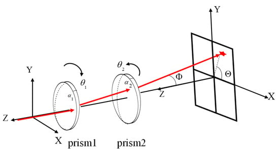
Figure 3.
The beam deflection model of the Risley prism system. The red star indicates the deflected position of the incident light beam after passing through the Risley prism. The red arrows represent the beam path.
Current research on the Risley prism system primarily focuses on model analysis, scanning, and target tracking on static platforms. The model analysis of the Risley prism system has been well-developed. Zhou et al. explored the complete analytical solutions to both the forward and inverse problems of the Risley prism system using first-order paraxial approximation and non-paraxial ray tracing methods [10,11]. Li developed and validated a two-step method aimed at enhancing the precision of the inverse analytical solution for the Risley prism system. This method significantly improves the beam-pointing precision of the Risley prism system under complex operational conditions [12]. To resolve the blind spot problem in the Risley prism system, Li AH et al. developed a theoretical framework for the three-element Risley prism system. They formulated both forward and inverse analytical solutions for this model and performed quantitative analyses to determine the critical conditions for eliminating the blind spot [13]. Yuan et al. introduced an analytical inverse solution method for the achromatic Risley prism system based on Fourier series fitting, aiming to improve the accuracy of iterative inverse calculation methods [14]. These solution models provide a theoretical foundation for target acquisition using the Risley prism system.
The Risley prism is extensively utilized in contemporary scanning applications, with implementations across both static and motion platforms. Its applications span various fields, including biomedical engineering, military applications, and lidar systems. Duncan proposed a chromatic aberration-corrected Risley prism system for infrared countermeasures [15]. Tang developed a near-infrared single-photon LiDAR system based on a Risley prism scanner [16]. Huang introduced a collaborative correction method for field-of-view distortion and dispersion in a Risley prism imaging system used in biomimetic human-eye imaging [17].
Recent studies have expanded the application of the Risley prism system to target tracking. Scholars such as Li AH, Zhou Y, and Li JY have advanced diverse image-based closed-loop tracking methodologies for the Risley prism system, aiming to resolve the coupling challenge between image detector feedback and prism rotation angles [18,19,20]. To improve the tracking and scanning accuracy of the Risley prism system, researchers have proposed the cascaded rotation Risley-prism pairs and the composite axis system that combines the Risley prism with a fast steering mirror (FSM) [21,22,23,24]. Wang et al. [23] investigated the coupling relationship between the optical axis of the Risley prism system and the motion of the optical base on a motion platform by employing the velocity loop in the servo control framework. Their study successfully achieved the stabilization of the optical axis of the Risley prism system, laying a theoretical foundation for LOS stabilization studies on motion platforms. However, the research primarily emphasized the design of target tracking controllers and composite axis control strategies, while providing limited analysis of the system’s disturbance rejection and LOS stabilization performance under dynamic platform motion. To date, most investigations into target tracking using the Risley prism system have been confined to static platforms, with limited exploration of its performance and applicability on motion platforms.
In our team’s previous work, we addressed the coupling problem between the miss distance on the image detector and the prism’s rotation angle using a rotation matrix method, enabling image-based closed-loop target tracking for the Risley prism system [20]. To solve the nonlinear issues in target tracking with the Risley prism, we proposed a multivariable decoupling and variable-gain control method to achieve smooth tracking of targets in different field-of-view regions [25]. We then introduced a cascaded control system with a single detector combining the Risley prism and fast steering mirror, providing a decoupling method for coarse and fine control inputs to achieve fast and high-precision target tracking [24]. In our previous work, the focus was primarily on static platforms, leaving the challenges associated with motion platforms unaddressed. However, motion platforms significantly expand the application scope in target acquisition, aiming, and tracking. Consequently, the stabilization of LOS and the development of target tracking technologies for the Risley prism system on motion platforms remain critical challenges that require urgent resolution.
This paper introduces a novel strapdown LOS stabilization method for the Risley prism system on motion platforms, which is based on the position loop of the servo control. Upon achieving LOS stabilization, the IBCLTCR-F system is employed to enable fast and high-precision target tracking on the motion platform. First, the transformation relationship between the motion platform coordinate system and the Risley prism system coordinate system is established. Then, the attitude angle changes in the motion platform are measured in real-time using the IMU, and the direction cosine matrix is calculated using the direction cosine matrix method. The actual guidance position of the target in the Risley prism coordinate system under platform motion is subsequently determined. The prism rotation angles are computed to capture the target and achieve LOS stabilization. Finally, the IBCLTCR-F system is used for image-based closed-loop target tracking. Compared to existing research on LOS stabilization and target tracking using the Risley prism system on motion platforms, this paper establishes a coupling model between platform motion and the Risley prism system through comprehensive theoretical analysis. This model allows for the direct calculation of the compensatory rotation angle of Risley prism required to offset the LOS shift induced by platform motion, thereby achieving LOS stabilization. Furthermore, the IBCLTCR-F system is applied to the motion platform in this paper, further enhancing the target tracking capability of the Risley prism system during platform motion.
The structure of this paper is organized as follows: Section 2 presents an analysis of LOS stabilization for the Risley prism system on a motion platform. Section 3 provides a detailed explanation of the working principles of LOS stabilization and the IBCLTCR-F system on a motion platform. Section 4 presents experimental validation.
2. Strapdown LOS Stabilization Algorithm for the Risley Prism System
The proposed model of the Risley prism system on the motion platform is depicted in Figure 4. In this model, a light source simulates the target, while a six-degree-of-freedom (6-DOF) platform emulates the motion platform. An IMU installed on the motion platform measures its angular variations in inertial space in real-time. The Risley prism system is implemented as an achromatic Risley prism, and the model, along with the beam deflection calculation formulas, can be referenced in the relevant literature [26].
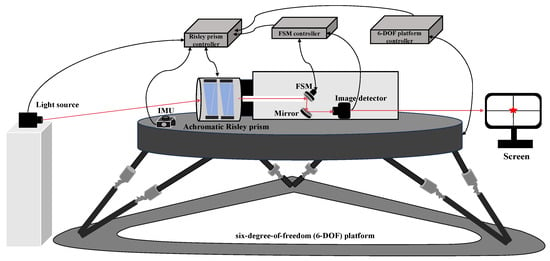
Figure 4.
Model of the Risley prism system on the motion platform.
2.1. Coordinate System Transformation Relationship
In this study, it is assumed that the Risley prism system is rigidly mounted on the motion platform, with the motion of the platform directly transmitted to the Risley prism system. The origin of the Risley prism’s rectangular coordinate system coincides with that of the motion platform’s rectangular coordinate system. The Z-axis is the rotation axis, the Y-axis represents the azimuth axis, and the X-axis represents the pitch axis. The axes form a right-handed Cartesian coordinate system. In the present study, the effect of the roll angle of the motion platform is temporarily disregarded. The coordinate systems of the Risley prism system and the motion platform are illustrated in Figure 5.
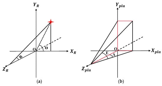
Figure 5.
Coordinate system definitions. (a) Coordinate system of the Risley prism system. (b) Coordinate system of the motion platform.
In the Risley prism coordinate system , represents the target pitch angle, and represents the target azimuth angle. In the motion platform coordinate system, denotes the variation in the platform’s azimuth axis, and denotes the variation in the platform’s pitch axis. The transformation relationship between the Risley prism coordinate system and the motion platform coordinate system is shown in Figure 6.
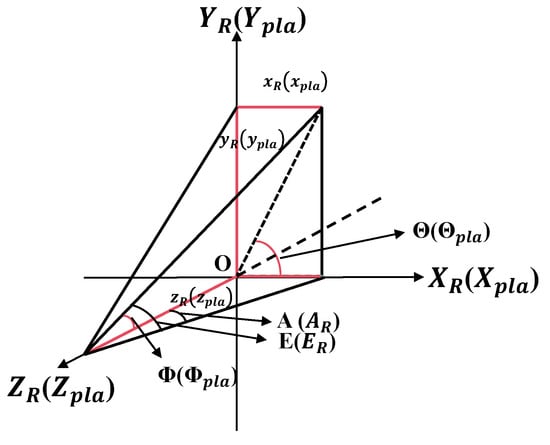
Figure 6.
Transformation relationship between the Risley prism system coordinate system and the motion platform coordinate system.
By referring to Figure 6, the target in the Risley prism’s polar coordinate system can be transformed into the corresponding values in the motion platform’s Cartesian coordinate system, as well as into the values in the motion platform’s polar coordinate system. The rotation axis is treated as a unit vector.
Similarly, the variations of the azimuth and pitch axes caused by platform motion can be transformed into the corresponding values in the Risley prism system’s Cartesian coordinate system, as well as into the values in the Risley prism system’s polar coordinate system.
2.2. Direction Cosine Matrix
The are measured using the IMU installed on the motion platform. The rectangular coordinate system of the motion platform first rotates angle around the azimuth axis, yielding the azimuth direction rotation matrix and the rotated coordinate system . Then, the rectangular coordinate system rotate the rotation angle around the pitch axis to obtain the pitch direction rotation matrix and rotated coordinate system . The direction cosine matrix (DCM) is obtained by multiplying the azimuth rotation matrix and the pitch rotation matrix . The coordinate system rotation relationship of the motion platform is shown in Figure 7.
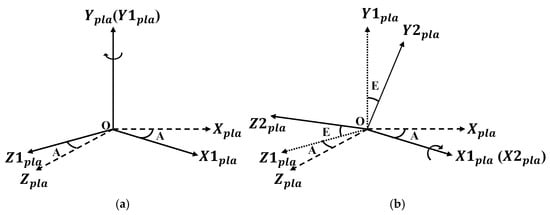
Figure 7.
Rotation relationships of the motion platform coordinate axes. (a) Rotation of the motion platform around the azimuth axis. (b) Rotation of the motion platform around the pitch axis.
2.3. Calculation of the Actual Target Guidance Position
In the Risley prism system, an initial guidance position of target can be transformed into the original guidance position of target value in the motion platform Cartesian coordinate system using (1). Multiplying this value by the direction cosine matrix yields the target value in the Cartesian coordinate system after the motion of the motion platform.
Based on Figure 6, the target value is transformed into the Risley prism’s polar coordinate system, resulting in the actual guidance position of target under the motion of the motion platform.
The target represents the actual guidance position of the target within the Risley prism system after accounting for the motion of the platform. The Risley prism inverse solution method [12] is subsequently employed to calculate the rotation angles required to align the system’s LOS with the target. This process enables target acquisition and stabilizes imaging on the image detector, thereby achieving LOS stabilization for the system.
3. Principles of LOS Stabilization and Target Tracking for the Risley Prism on the Motion Platform
The schematic block diagram illustrating the principle of LOS stabilization and target tracking for the Risley prism system on the motion platform is provided in Figure 8, and the corresponding workflow is depicted in Figure 9.

Figure 8.
Block diagram of the operating principle for the Risley prism system on the motion platform.
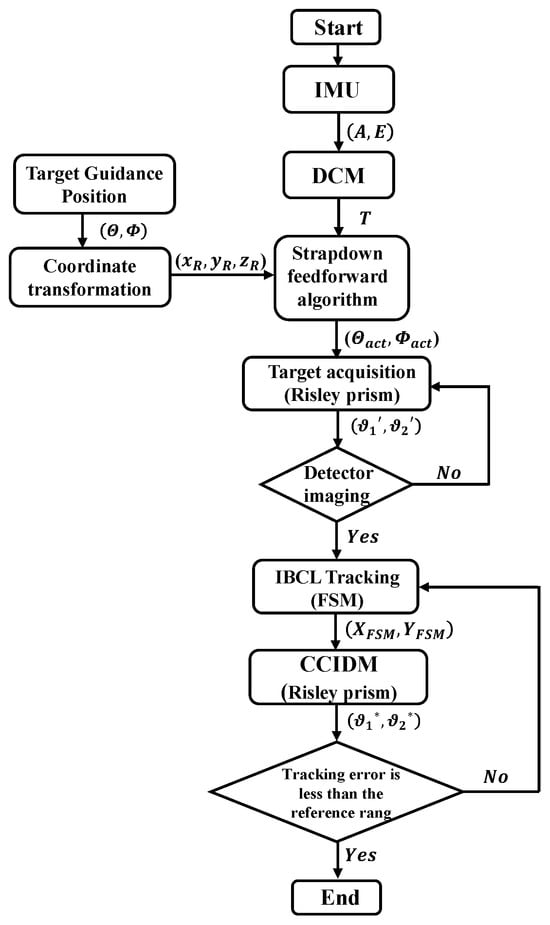
Figure 9.
Workflow diagram of the LOS stabilization and target tracking of the Risley prism on the motion platform.
Firstly, as the motion platform moves, the IMU measures its angular variations in inertial space and computes the corresponding direction cosine matrix. Secondly, using the coordinate system transformation relationships, the original guidance position of the target in the polar coordinate system of the Risley prism is transformed into the corresponding values in the Cartesian coordinate system of the motion platform. Thirdly, using the strapdown LOS stabilization algorithm, the actual guidance position of the target in the Cartesian coordinate system of the motion platform is calculated. The position of the target is then transformed back into the actual guidance position of the target in the polar coordinate system of the Risley prism. Finally, based on the , the rotation angles of the Risley prisms are calculated.
These four steps collectively achieve LOS stabilization of the Risley prism system under platform motion, ensuring that the target is successfully captured and positioned within the image detector’s field of view.
When the target enters the image detector’s field of view, IBCL tracking is initiated. First, the miss distance of image detector serves as the input for the FSM, and the FSM deflection angles are calculated to reduce the miss distance. Next, in the IBCLTCR-F system, the cascade control input decoupling method (CCIDM) [24] utilizes real-time FSM deflection angle feedback from its angle sensor as input to the Risley prism system during IBCL tracking. Finally, the rotation matrix error decoupling method [20] computes the Risley prism rotation angles , compensating for FSM deflection and ensuring that FSM deflection remains within operational limits. The miss distance on the image detector, representing the tracking error, is evaluated to determine whether it falls within the reference range. If the tracking error is within the range, the target tracking task is considered completed. Otherwise, if the error exceeds the range, the deflection angles of the FSM, and the rotation angles of the Risley prism are recalculated based on the miss distance. These three steps enable fast and high-precision target tracking in the Risley prism system on the motion platform.
4. Experiment
4.1. Disturbance Rejection Capability Analysis of the Risley Prism System
A frequency response analyzer generates a sine wave excitation signal with a 1°amplitude and a frequency range of 0.1–500 Hz, applied as input excitation for the Risley prism system. The analyzer’s two receiving channels collect both the excitation signal and the feedback signal from the Risley prism system’s encoder. From these signals, the frequency response curve of the system is obtained, and the fitted curve is used to derive the system’s servo transfer function. The frequency response curves are shown in Figure 10.
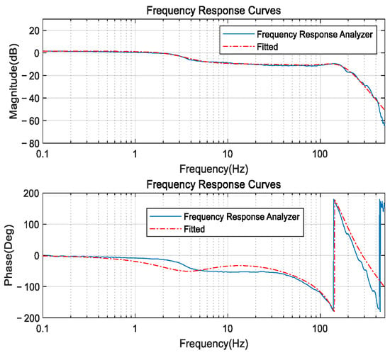
Figure 10.
Frequency response curves.
The servo transfer function of the Risley prism system is obtained by fitting the curve, as shown in the following equation.
The servo controller for the Risley prism system is designed based on the servo transfer function , as shown below.
The disturbance rejection simulation model of the Risley prism system is constructed based on (13) and (14), as shown in Figure 11.

Figure 11.
The disturbance rejection simulation model.
In this simulation model, In1 represents the desired input information of the Risley prism system on the motion platform, while Out denotes the output information of the Risley prism system on the motion platform. In2 serves as the disturbance input. The as the servo controller. The Fun 1 in Figure 11 corresponds to the strapdown LOS stabilization algorithm described in Section 2. The output of Fun 1 provides the rotation angle that compensates for the platform motion in the Risley prism system. In the absence of Fun 1, the rotation of the Risley prism system is solely determined by the rotation angle calculated from the original target guidance position. In such cases, platform motion will directly affect the LOS variation. With the inclusion of Fun 1, the rotation of the Risley prism is a combination of the rotation angle derived from the original target guidance position and the additional rotation angle due to the platform motion. The sum of these two components corresponds to in Figure 9, which helps mitigate the impact of platform attitude changes on the LOS. The simulation model calculates the Bode plot between In2 and Out, allowing for an analysis of the Risley prism system’s disturbance rejection capability at various frequencies. Figure 12 and Table 1 present the disturbance rejection Bode plot and the system’s disturbance rejection performance at different frequencies, respectively.
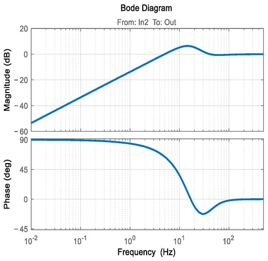
Figure 12.
Disturbance rejection Bode plot.

Table 1.
Disturbance rejection capability of the Risley prism.
4.2. LOS Stabilization Experiment of the Risley Prism System on the Motion Platform
Figure 13 shows the experimental platform of the Risley prism system on the motion Platform. The experimental platform consists of a light source, a gimbal-mounted Meade telescope, an achromatic Risley prism, a 6-DOF platform, an IMU, and a detection system. The field of view of the achromatic Risley prism is . The 6-DOF platform simulates the motion platform and is controlled by computer software to move in both azimuth and pitch directions. The IMU, mounted on the 6-DOF platform, measures and calculates the real-time attitude variations in azimuth and pitch. In the experimental platform, the IMU adopts an optical fiber gyroscope, featuring a zero bias stability better than 0.05°/h, a maximum input rate of ±600°/s, a data update rate of 1000 Hz, and a random walk coefficient below 0.002°/. The attitude variation in the motion platform is obtained by integrating the angular velocity measured by the optical fiber gyroscope. To reduce the cumulative error caused by the zero drift characteristic of the optical fiber gyroscope during the integration process, a zero bias calibration was performed prior to the experiments.
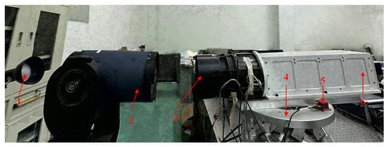
Figure 13.
Experimental platform. 1. Light source. 2. Gimbal-mounted Meade telescope. 3. Achromatic Risley prism. 4. 6-DOF platform. 5. IMU. 6. Detection system.
The target is generated by a combination of the light source and a gimbal-mounted Meade telescope. The light source passes through the gimbal-mounted Meade telescope, and by adjusting the azimuth and pitch axes of the gimbal-mounted Meade telescope, the outgoing light source position is changed to obtain different target locations. The target, after refraction through the achromatic Risley prism, is processed by the detection system and imaged on the image detector. The image detector has a field of view of 480 arcsec, a pixel of , and a sampling frequency of 50 Hz.
A static target is specified with an azimuth angle of 44.913° and a pitch angle of 1.257° in the polar coordinate system of the Risley prism. The target’s position within the system’s field of view is illustrated in the Figure 14. The field of view segmentation for the Risley prism system follows the methodology outlined in this paper [25].
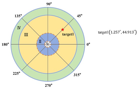
Figure 14.
Position of the static guided target1.
The 6-DOF platform is operated using computer-controlled software to execute sinusoidal trajectories in the azimuth direction and cosine trajectories in the pitch direction, each at three distinct frequencies. The motion trajectories corresponding to these three sets of movements are defined as follows.
The IMU is used to measure the real-time motion data of the 6-DOF platform in the azimuth and pitch directions during the above three sets of movements. The results are shown in the figure below.
The calculations based on Figure 15 and Figure 16 show that the maximum and minimum motion variations in the azimuth and pitch directions of the six-degree-of-freedom platform trajectories within one cycle are 74.2″ and 68.2″, respectively. These values are in close agreement with the set trajectory amplitude of 72″, thereby confirming the accuracy of the measurements.

Figure 15.
Azimuth angle changes in the 6-DOF platform. (a) First set. (b) Second set. (c) Third set.

Figure 16.
Pitch angle changes in the 6-DOF platform. (a) First set. (b) Second set. (c) Third set.
The actual guidance position of the target for the 6-DOF platform under three different motion trajectories is calculated using (11) and (12) from the LOS stabilization algorithm. A comparison of the target’s original and actual guidance positions, as shown in Figure 17 and Figure 18, is presented below.

Figure 17.
Comparison of the original and actual target guidance azimuth angles in the polar coordinate system of the Risley prism under three different 6-DOF platform motion trajectories. (a) First set. (b) Second set. (c) Third set.

Figure 18.
Comparison of the original and actual target guidance pitch angles in the polar coordinate system of the Risley prism under three different 6-DOF platform motion trajectories. (a) First set. (b) Second set. (c) Third set.
The Risley prism system is employed to capture and track the target. Figure 19 records the miss distance on the image detector during the target capture and tracking processes under three different 6-DOF platform motion trajectories, with and without the LOS stabilization algorithm. Phase I illustrates the variation in miss distance during the target acquisition process using the Risley prism, while Phase II represents the miss distance changes during the IBCL target tracking process. The miss distance is calculated using the following formula.
where is the miss distance along the X-axis of the image detector, and is the miss distance along the Y-axis of the image detector.

Figure 19.
Comparison of miss distance of the image detector with and without LOS stabilization algorithm under three different 6-DOF platform motion trajectories. (a) First set. (b) Second set. (c) Third set.
As shown in Figure 19, the application of the LOS stabilization algorithm during 6-DOF platform motion substantially mitigates the miss distance of the image detector during target acquisition, demonstrating the algorithm’s efficacy in achieving effective LOS stabilization. Furthermore, during the IBCL tracking process, the use of the LOS stabilization algorithm significantly reduces the tracking error.
The following will provide a detailed analysis of the disturbance rejection capability and target tracking performance of the Risley prism system on the motion platform after applying the LOS stabilization algorithm. To analyze the disturbance rejection capability of the Risley prism system on the motion platform, we conducted time-domain and frequency-domain analyses of the miss distance variation and the motion variation in the 6-DOF platform during the target acquisition process using the LOS stabilization algorithm. Figure 20 presents the time-domain and frequency-domain plots for these parameters under three distinct 6-DOF platform motion trajectories. Table 2 summarizes the disturbance rejection capability of the Risley prism system under three different frequency 6-DOF platform motion trajectories using the LOS stabilization algorithm.

Figure 20.
Time-domain and frequency-domain plots under three different 6-DOF platform motion trajectories. (a) First set. (b) Second set. (c) Third set.

Table 2.
Disturbance rejection capability.
As shown in Figure 20 and Table 2, the disturbance rejection capability of the Risley prism system on the motion platform using the LOS stabilization algorithm aligns closely with the simulation analysis in Table 1, demonstrating the feasibility of the proposed LOS stabilization algorithm.
The IBCL tracking of the target was performed under three different 6-DOF platform motion trajectories, both with and without the LOS stabilization algorithm. A comparison of the steady-state tracking errors is shown in Figure 21.

Figure 21.
The steady-state tracking errors under three different 6-DOF platform motion trajectories. (a) First set. (b) Second set. (c) Third set.
Table 3 presents the root mean square (RMS) values of the steady-state tracking errors for the IBCL tracking of the target, performed with three different 6-DOF platform motion trajectories, both with and without the LOS stabilization algorithm.

Table 3.
Tracking errors.
As shown in Figure 21 and Table 3, for 6-DOF platform motion at frequencies of 0.05 Hz, 0.2 Hz, and 0.5 Hz, the IBCL tracking error of the Risley prism system using the LOS stabilization algorithm was reduced by 90.7%, 88.4%, and 82.2%, respectively. This significantly enhanced the target tracking capability of the Risley prism system on the motion platform.
4.3. Fast and High-Precision Target Tracking Experiment of the Risley Prism System on the Motion Platform
The experimental platform for fast and high-precision target tracking of the Risley prism system on the motion platform requires modifying the detection system based on the setup in Figure 13, transforming it into the fine control system described in reference [24]. This experimental platform represents the IBCLTCR-F system mounted on the motion platform. In the experiment, the pitch and azimuth angles of two guided targets are provided: target 2 and target 3 The positions of these two targets within the field of view of the Risley prism are shown in the Figure 22.
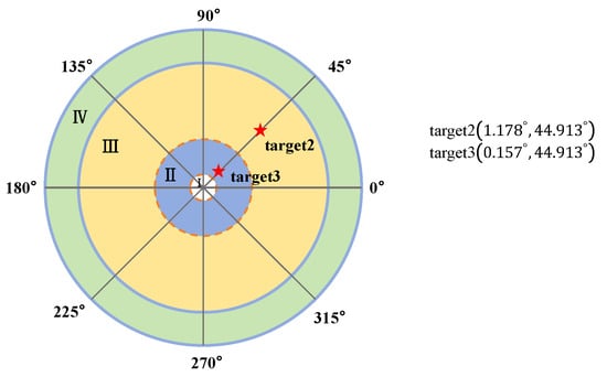
Figure 22.
Positions of the static guided target 2 and target 3.
Target 2 is located in a region of the field of view where the nonlinear effects of the Risley prism have a minimal impact on dynamic tracking performance, whereas target 3 is situated in a region where these nonlinear effects significantly influence dynamic tracking performance [25].
The 6-DOF platform was controlled via computer software to operate along the first set of motion trajectories. After successfully capturing the target and stabilizing the image on the image detector using the LOS stabilization algorithm, the Risley prism system and the IBCLTCR-F system were used to perform IBCL tracking on target 2 and target 3, respectively. During this process, the miss distance on the image detector was recorded, as shown in the following figure.
Table 4 and Table 5 present the dynamic response time and steady-state tracking error during the IBCL tracking of target 2 and target 3 using the Risley prism system on the motion platform. Additionally, they provide the dynamic response time and steady-state tracking error for the IBCL tracking of the same targets using the IBCLTCR-F system.

Table 4.
Dynamic response time.

Table 5.
Steady-state tracking error.
From Figure 23, Table 4 and Table 5, it can be observed that on the motion platform, the IBCLTCR-F system significantly enhances IBCL tracking performance after LOS stabilization. Specifically, the dynamic response capability of the IBCLTCR-F system is more than five times greater than that of the Risley prism system, while the steady-state tracking error is reduced by 30%. For targets within regions of significant nonlinearity, the dynamic response capability of the IBCLTCR-F system exceeds that of the Risley prism by more than ten times, with the tracking error reduced by 70%. Experimental results demonstrate that the IBCLTCR-F system achieves fast and high-precision target tracking on a moving platform.
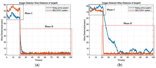
Figure 23.
Image detector miss distance. (a) Target 2. (b) Target 3.
Furthermore, we conducted capture and tracking experiments on a moving target. The 6-DOF platform was controlled via computer software to follow a trajectory. The motions of the 6-DOF platform in the azimuth and pitch directions, measured in real-time by the IMU, are shown in Figure 24.
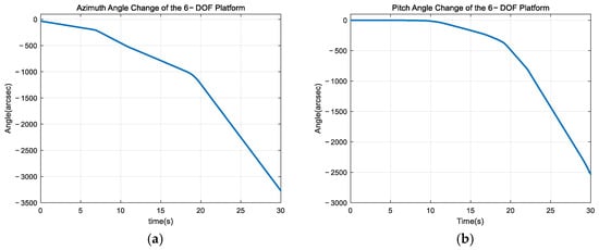
Figure 24.
Motions of the 6-DOF platform in the azimuth and pitch directions. (a) Azimuth direction. (b) Pitch direction.
Meanwhile, the Gimbal-mounted Meade telescope was controlled to follow a trajectory, generating the original guidance trajectory of moving target 4. The actual guidance trajectory of target 4 was then calculated using the strapdown LOS stabilization algorithm. A comparison between these two trajectories is shown in Figure 25.
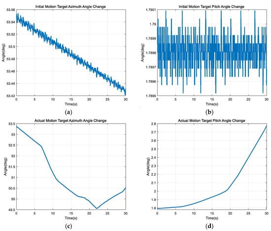
Figure 25.
Guidance trajectory of target 4. (a) Initial guidance azimuth angle. (b) Initial guidance pitch angle. (c) Actual guidance azimuth angle. (d) Actual guidance pitch angle.
Figure 26 illustrates the miss distance on the image detector during IBCL tracking of target 4 using the IBCLTCR-F system after LOS stabilization and target acquisition. Without the LOS stabilization algorithm, target 4 could not be reliably acquired on the image detector, making it impossible to record the miss distance.
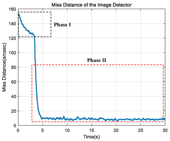
Figure 26.
Miss distance on the image detector during the acquisition and tracking of target 4.
As shown in Figure 26, when the target and motion platform follow random trajectories, the strapdown stabilization algorithm ensures LOS stability. Subsequently, the IBCLTCR-F system successfully tracks the target. This demonstrates the feasibility of the proposed LOS stabilization algorithm and IBCLTCR-F system on the motion platform.
5. Conclusions
In this paper, a method for LOS stabilization and high-precision target tracking using a Risley prism system on the motion platform is proposed, based on prior research. First, the coordinate systems of the Risley prism system and the motion platform are defined, and their transformation relationship is established. This allows for the calculation of the target’s position in both the Risley prism and motion platform coordinate systems. Second, IMU is used to measure and calculate the changes in the motion platform’s azimuth and pitch angles, from which the direction cosine matrix is derived. The actual target guidance position after platform movement is calculated using the direction cosine matrix, followed by the computation of the rotation angle for the Risley prism system to stabilize the LOS and capture the target image on the image detector. Finally, the IBCLTCR-F system is applied to the motion platform. Once LOS stabilization is achieved and the target is successfully captured on the detector, the IBCLTCR-F system is used for fast and high-precise image-based closed-loop tracking of the target. This study expands the application scenarios of electro-optical imaging and tracking systems based on the Risley prism.
When the motion frequency of the platform is excessively high, the bandwidth limitation of the Risley prism system hinders its ability to effectively suppress the impact of the platform’s attitude variations on the line-of-sight, resulting in a decline in target tracking accuracy. To further enhance the system’s line-of-sight stability in high-frequency dynamic environments, future research may consider integrating a composite axis system, combining the Risley prism with other high dynamic response actuators to achieve improved line-of-sight stability and enhance the system’s target tracking performance on complex motion platforms.
Author Contributions
Conceptualization, J.L. and H.X. (Huayang Xia); methodology, J.L., H.X. (Huayang Xia) and Y.X.; software, H.X. (Huayang Xia) and J.L.; validation, H.X. (Huayang Xia), H.X. (Hongfeng Xia) and L.Y.; formal analysis, H.X. (Huayang Xia); investigation, H.X. (Huayang Xia) and J.L.; resources, J.L., H.M. and Y.L.; data curation, H.X. (Huayang Xia), W.Y. and P.W.; writing—original draft preparation, H.X. (Huayang Xia); writing—review and editing H.X. (Huayang Xia) and J.L.; visualization, H.X. (Huayang Xia); supervision, J.L.; project administration, J.L. All authors have read and agreed to the published version of the manuscript.
Funding
This research received no external funding.
Data Availability Statement
Data are contained within the article.
Conflicts of Interest
The authors declare no conflict of interest.
References
- Ricks, T.P.; Burton, M.M.; Cruger, W.; Reynolds, R. Stabilized electro-optical airborne instrumentation platform (SEAIP). Proc. SPIE Int. Soc. Opt. Eng. 2004, 5268, 202–209. [Google Scholar]
- Lu, P.G.; Shou, S.J. High accuracy tracking technology and its application in ship-borne electro-optical system. J. Appl. Opt. 2006, 27, 1002–2082. [Google Scholar]
- Xu, T.; Li, B.; Liu, T.; Xue, L.T.; Chen, T. Initial calibration of tracking turntable for vehicle-borne opto-electronic tracking system. Opt. Precis. Eng. 2013, 21, 782–789. [Google Scholar]
- Song, J.; Sun, G.; Zhou, D.; Huimin, C. Line-of-sight stabilization techniques for mirror electro-optical platform. Infrared Laser Eng. 2015, 44, 1904–1911. [Google Scholar]
- Li, X.; He, M.; Tuo, W.; Wang, T.; Han, J.; Wang, X. Review on inertial reference unit applied to photoelectric tracking and pointing system of moving platform. Opt. Precis. Eng. 2024, 32, 401–421. [Google Scholar] [CrossRef]
- Kennedy, P.J.; Kennedy, R.L. Direct versus indirect line of sight (LOS) stabilization. Ieee Trans. Control Syst. Technol. 2003, 11, 3–15. [Google Scholar] [CrossRef]
- Marshall, G.F. Risley Prism scan patterns. In Conference on Optical Scanning—Design and Application; SPIE: Denver, CO, USA, 1999; pp. 74–86. [Google Scholar]
- Ostaszewski, M.; Harford, S.; Doughty, N.; Hoffman, C.; Sanchez, M.; Gutow, D.; Pierce, R. Risley Prism Beam Pointer. In Conference on Free-Space Laser Communications VI; SPIE: San Diego, CA, USA, 2006. [Google Scholar]
- Fan, D.P.; Zhou, Y.; Lu, Y.F.; Hei, M.; Xiong, F.T.; Li, K. Overview of beam steering technology based on rotational double prisms. Chin. Opt. 2013, 6, 136–150. [Google Scholar]
- Zhou, Y.; Lu, Y.; Hei, M.; Xiong, F.R.; Li, K.; Fan, D.P. Analytic solution of optical beam steering based on rotational double prisms. Opt. Precis. Eng. 2013, 21, 1373–1379. [Google Scholar] [CrossRef]
- Zhou, Y.; Lu, Y.; Hei, M.; Xiong, F.R.; Li, K.; Fan, D.P. Analytical Inverse Solutions for Rotational Double Prism Beam Steering. Opt. Precis. Eng. 2013, 21, 1693–1700. [Google Scholar] [CrossRef]
- Li, Y.J. Closed form analytical inverse solutions for Risley-prism-based beam steering systems in different configurations. Appl. Opt. 2011, 50, 4302–4309. [Google Scholar] [CrossRef]
- Li, A.H.; Liu, X.S.; Sun, W.S. Forward and inverse solutions for three-element Risley prism beam scanners. Opt. Express 2017, 25, 7677–7688. [Google Scholar] [CrossRef] [PubMed]
- Yuan, L.Z.; Li, J.Y.; Huang, Y.M.; Wen, P.; Shi, J.; Xia, H.; Ma, R. Analytical inverse solution of a rotational achromatic Risley prism based on Fourier series fitting. Precis. Eng. J. Int. Soc. Precis. Eng. Nanotechnol. 2023, 80, 20–29. [Google Scholar] [CrossRef]
- Duncan, B.D.; Bos, P.J.; Sergan, V. Wide-angle achromatic prism beam steering for infrared countermeasure applications. Opt. Eng. 2003, 42, 1038–1047. [Google Scholar]
- Tan, C.S.; Kong, W.; Huang, G.H.; Jia, S.; Liu, Q.; Han, Q.; Hou, J.; Xue, R.; Yu, S.; Shu, R. Development of a near-infrared single-photon 3D imaging LiDAR based on 64x64 InGaAs/InP array detector and Risley-prism scanner. Opt. Express 2024, 32, 7426–7447. [Google Scholar] [CrossRef]
- Huang, F.; Huang, D.H.; Yang, S.M.; Wang, P. Cooperative correction method for distortion and dispersion of deflected field of view in Risley-prism bionic-human-eye imaging systems. Opt. Express 2024, 32, 5444–5459. [Google Scholar] [CrossRef]
- Zhou, Y.; Chen, Y.; Sun, L.P.; Hu, F.; Wang, Z.; Fan, S. Analysis on key issues of boresight adjustment in imaging tracking based on Risley prisms. Opt. Eng. 2020, 59, 123104. [Google Scholar] [CrossRef]
- Li, A.H.; Zhao, Z.S.; Liu, X.S.; Deng, Z. Risley-prism-based tracking model for fast locating a target using imaging feedback. Opt. Express 2020, 28, 5378–5392. [Google Scholar] [CrossRef]
- Li, J.; Yuan, L.; Xia, H.; Huang, Y.; Ma, R.; Shi, J.; Wen, P.; Peng, C. Rotation matrix error-decoupling methods for Risley prism closed-loop tracking. Precis. Eng. J. Int. Soc. Precis. Eng. Nanotechnol. 2022, 76, 66–74. [Google Scholar] [CrossRef]
- Li, A.H.; Sun, W.S.; Liu, X.S.; Gong, W. Laser coarse-fine coupling tracking by cascaded rotation Risley-prism pairs. Appl. Opt. 2018, 57, 3873–3880. [Google Scholar] [CrossRef]
- Ma, X.G.; Zhang, W.B.; Tao, Y. Research on Real-Time Precision Control Technology of Composite Axis of Risley Double Prisms and FSM. Machinery 2022, 49, 22–31. (In Chinese) [Google Scholar]
- Wang, J.; Song, Y.; Liu, Y.; Zhang, J. Beam Compound Tracking Control Technology Based on Rotating Double Prism. Acta Photonica Sin. 2023, 52, 0211005. [Google Scholar]
- Xia, H.Y.; Xia, Y.X.; Yuan, L.Z.; Wen, P.; Zhang, W.; Ding, K.; Fan, Y.; Ma, H.; Li, J. Fast and high-precision tracking technology for image-based closed-loop cascaded control system with a Risley prism and fast steering mirror. Opt. Express 2024, 32, 8555–8571. [Google Scholar] [CrossRef] [PubMed]
- Xia, H.; Li, J.; Xia, Y.; Yuan, L.; Zhang, W.; Ma, H.; Wen, P. Multivariable Decoupling and Nonlinear Correction Method for Image-Based Closed-Loop Tracking of the Risley Prisms System. Micromachines 2022, 13, 2096. [Google Scholar] [CrossRef] [PubMed]
- Li, J.; Chen, K.; Peng, Q.; Wang, Z.; Jiang, Y.; Fu, C.; Ren, G. Improvement of pointing accuracy for Risley prisms by parameter identification. Appl. Opt. 2017, 56, 7358–7366. [Google Scholar] [CrossRef]
Disclaimer/Publisher’s Note: The statements, opinions and data contained in all publications are solely those of the individual author(s) and contributor(s) and not of MDPI and/or the editor(s). MDPI and/or the editor(s) disclaim responsibility for any injury to people or property resulting from any ideas, methods, instructions or products referred to in the content. |
© 2025 by the authors. Licensee MDPI, Basel, Switzerland. This article is an open access article distributed under the terms and conditions of the Creative Commons Attribution (CC BY) license (https://creativecommons.org/licenses/by/4.0/).