Article

Analysis and Optimization Design of a Brushless Power Feedback PM Adjustable Speed Drive with Bilayer Wound Rotor

1
School of Electrical Engineering, Southeast University, Nanjing 210096, China
2
Industrial Center, Nanjing Institute of Technology, Nanjing 211167, China
*
Author to whom correspondence should be addressed.
Actuators 2025, 14(5), 241; https://doi.org/10.3390/act14050241 (registering DOI)
Submission received: 3 April 2025 / Revised: 5 May 2025 / Accepted: 10 May 2025 / Published: 12 May 2025
(This article belongs to the Section High Torque/Power Density Actuators)

Abstract

:
A novel brushless power feedback permanent magnet adjustable speed drive (BLPF-PMASD) is developed for the energy-saving of a large power electrical machine drive system in this paper. It can transfer the slip power between the input and output shafts to a stator and then transmit it back to the power grid, achieving higher drive efficiency and stability. First, the topology feature, operation principle, and power feedback mechanism of the proposed drive are clearly illustrated. Second, a multi-objective optimization design method suitable for all working conditions is proposed to provide an effective design means for this type of adjustable speed drive with power feedback. Finally, the electromagnetic performance of the optimized drive is analyzed by using the finite element method (FEM) to demonstrate the effectiveness and superiority of the proposed drive.

1. Introduction

High-power fan and pump loads are widely used in energy-intensive industries, such as power generation, metallurgy, steel production, coal processing, cement manufacturing, and chemical production [1]. Usually, these loads are driven directly by alternating current (AC) induction motors, operating at an almost constant speed. However, the flows of pumps and fans often require flow adjustment to meet the varying demands of industrial applications [2]. Traditionally, flow regulation relies on the use of throttle valves, which function by altering the resistance within the flow passage. While this approach is able to adjust flows, it cannot effectively reduce the output power of the prime mover, leading to significant energy losses. Consequently, it is urgent to develop some energy-saving speed regulation technologies that can control the input speed of fans and pumps with high efficiency. The new technologies should be able to precisely regulate flow while minimizing the energy consumption of the prime mover.
Currently, two mainstream energy-saving speed regulation solutions in industrial systems are variable frequency drives (VFDs) and adjustable speed drives (ASDs), respectively [3]. However, VSDs face inherent limitations and significant technical challenges when used in large-capacity high-voltage motor drive systems. First, they inevitably introduce harmonic pollution into the power grid, which becomes particularly severe at high capacities. This issue adversely affects the operation of other electronic equipment and necessitates the deployment of harmonic mitigation devices [4,5]. Second, due to the relatively low reliability, high-voltage VSDs will frequently have operational failures, causing production interruptions and leading to substantial economic losses that outweigh the energy savings. Although many users recognize the ability of VFDs to achieve speed control and energy savings, they still remain hesitant to adopt VFDs due to the associated technical and operational challenges [6].
With the continuous advancements of the performance of permanent magnet (PM) materials, PM adjustable speed drive (PMASD) technology for energy-saving applications has garnered significant interest from researchers [7,8,9]. This technology leverages high-performance rare-earth PM materials to generate a magnetic field and manipulates this field by adjusting the gap between the rotating PMs and the metal conductor that produces eddy currents, thus achieving adjustable load speed and energy conservation [10,11,12]. Since there is no mechanical connection between the prime mover and the load, PMASD eliminates the transmission of load vibrations and issues related to shaft misalignment, significantly enhancing system reliability and reducing maintenance costs. It is worth mentioning that this technology does not introduce any harmonic pollution into the power grid. At present, various types of PMASD systems have been developed and are running in industrial production [13,14,15,16,17,18,19,20,21]. However, the slip power between the input and output terminals of PMASD is converted into eddy current losses within the conducting rotor and dissipated into the surrounding environment in the form of heat, categorizing it as a slip power consumption type. The efficiency of the drive is theoretically expressed as 1 s (s is the slip rate, and 0 < s < 1 ), and it decreases linearly as the slip increases. To mitigate this issue, a power feedback PMASD (PF-PMASD) was proposed in [22], which feeds the slip power back to the power grid through brushes and slip rings. This approach reduces conductor heating and improves the overall efficiency of the drive, and simultaneously alleviates the burden of lowering the ambient temperature. Nevertheless, the use of brushes and slip rings limits its applicability to certain scenarios and increases maintenance costs, so a reliable brushless design scheme is desperately needed.
In this paper, a brushless power feedback PM adjustable speed drive (BLPF-PMASD) with a double-layer wound rotor is developed, which is very suitable for the energy-saving transformation of fan and pump loads in industrial enterprises. The topology feature, operation principle, and power feedback mechanism of the proposed drive are intuitively illustrated. A multi-condition optimization design method is proposed to achieve the optimal design solution of this kind of drive. The electromagnetic characteristics of the optimized drive are analyzed by the finite element method (FEM), which demonstrates that it has higher efficiency and better speed adjustment performance.

2. Machine Topology, Operating Principle, and Power Feedback Mechanism

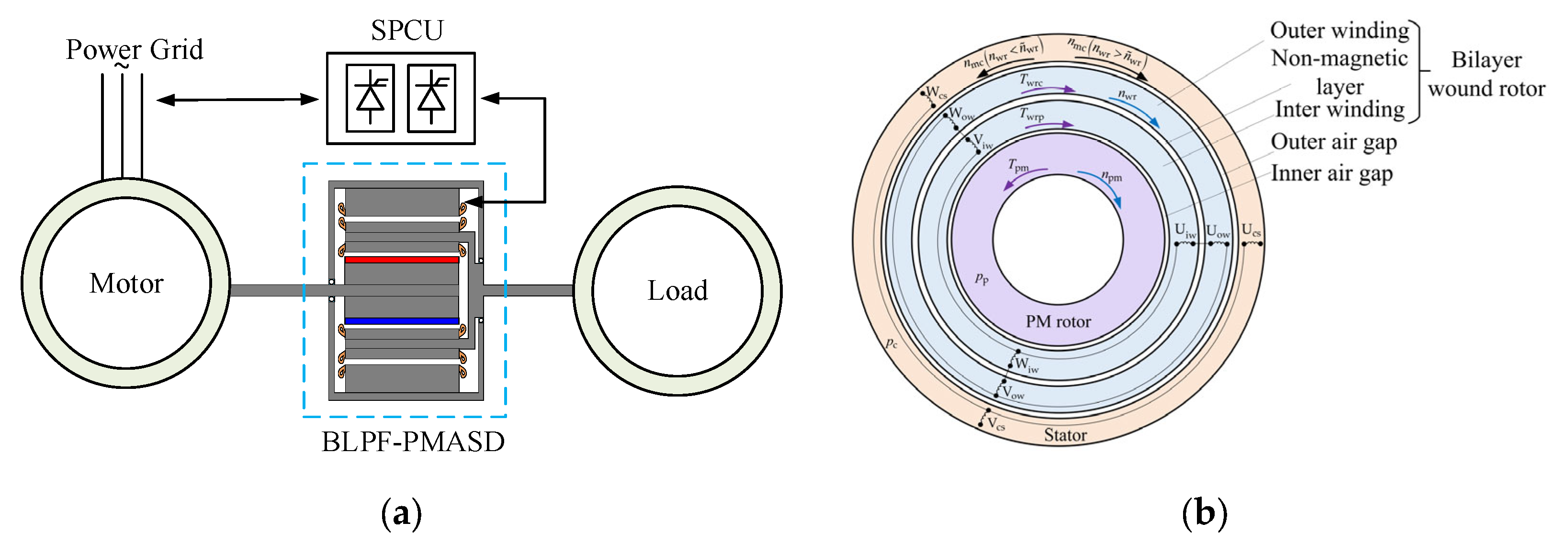
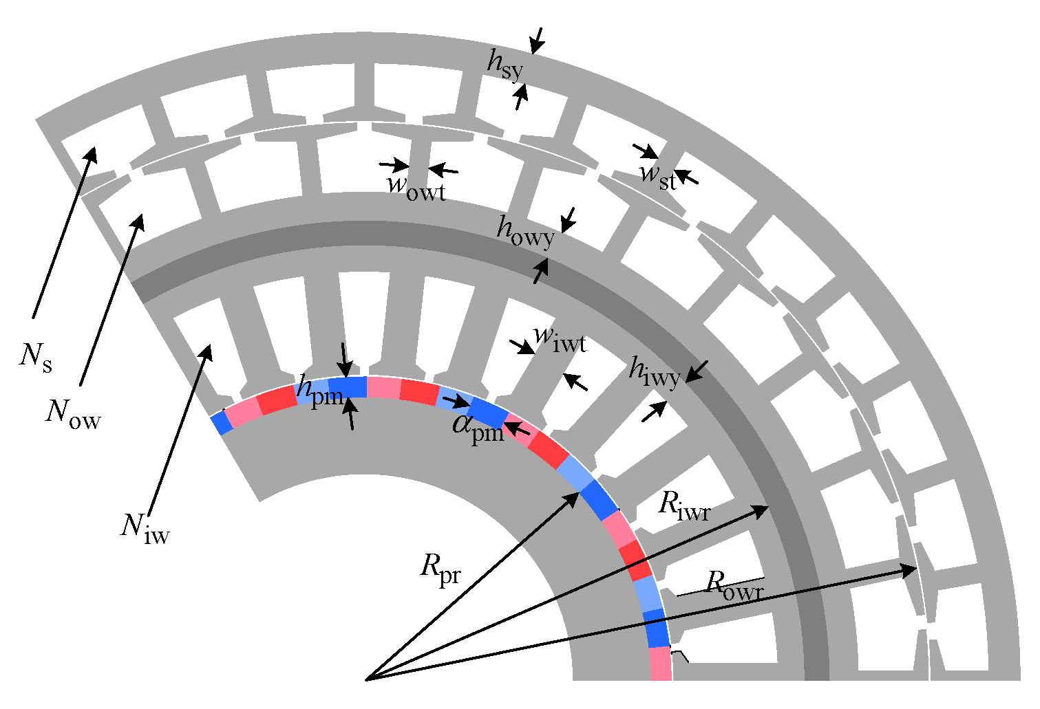
2.1. Machine Topology

The topology and winding configuration of the proposed BLPF-PMASD in this study are shown in Figure 1. The drive serves as a connecting device between the primary mover (usually a high-power induction motor) and the load, which is responsible for transmitting mechanical power and regulating load speed. It comprises three main components: a PM rotor, a dual-layer wound rotor, and a stator, as shown in Figure 1a. The PM rotor is directly connected to the primary mover to operate at an approximately constant speed, which is determined by the characteristics of the induction motor. The dual-layer wound rotor features two distinct sets of windings with different pole pair numbers, one inside the other, referred to as the inner winding and the outer winding, respectively. The magnetic circuits of the two sets of windings, namely the inner winding and the outer winding, are fixed on a steel non-magnetic cylinder, which is connected to the output shaft. The inner winding, in conjunction with the PM rotor, forms a power subsystem, which is responsible for generating the main electromagnetic torque. Meanwhile, the outer winding and the stator together constitute a control subsystem, which is responsible for adjusting the output speed of the load and converting the slip power into electrical power. The stator winding is connected to a slip power control unit (SPCU), which is used to regulate the output speed and torque of the wound rotor by controlling the frequency and amplitude of the stator winding current. The capacity of the SPCU accounts for only 20–30% of the rated power of the drive, offering significant advantages in terms of reduced cost and enhanced reliability compared with traditional VFD with full rated power. The inner winding and outer winding are connected in a negative phase sequence so that their magnetic fields rotate in the opposite direction, as illustrated in Figure 1b. This configuration, compared with the positive phase sequence connection, offers advantages of higher output torque and a wider speed regulation range.

2.2. Operating Principle of Speed Regulation

To clearly explain the operating principle and the power feedback mechanism of the proposed drive, the directions of the following physical quantities are specified:
(1)
The rotation direction of the PM rotor is defined as the positive direction;
(2)
The reference direction for the current at the stator’s electrical terminal is from the external circuit into the stator winding;
(3)
The electrical power at the stator’s electrical terminal is considered positive when it is input to the drive and negative when it is output from the drive.
The prime mover, usually an asynchronous motor, drives the PM rotor to rotate at an approximately constant speed, forming a rotating magnetic field with the speed of n pm . If the power subsystem generates a constant torque, the relationship between the current frequency f Iwr of the current in the inner winding and the rotational speed n wr of the wound rotor is expressed as follows:
f Iwr = p p n pm n wr 60
where p p is the pole-pair number of the power subsystem. The power subsystem provides a torque T wrp to the wound rotor, which is determined by the magnetic flux density of the inner air gap and the current of the inner winding.
The inner winding and outer winding are connected in series with a negative phase sequence, the currents of which have the same magnitude and frequency. The currents in the outer winding synergistically generate a rotating magnetic field in the outer layer of the wound rotor, the rotational speed of which can be expressed as follows:
n mc = 60   f Iwr p c + n wr = p c + p p n wr p p n pm p c
where p c is the pole-pair number of the control subsystem; the negative sign indicates that the rotating direction of the magnetic field in the outer air gap is opposite to that of the wound rotor.
When a three-phase symmetric current is injected into the stator winding, a rotating magnetic field is generated, which is required to rotate at the same speed as the rotating magnetic field of the outer winding to produce a stable torque. The relationship between the frequency of the stator winding current f c and the rotational speed of the wound rotor can be obtained as follows:
f c = p c n mc 60 = ± p p + p c 60 n wr f p
where f p is the alternating frequency of the PM rotor magnetic field, f p = p p n pm / 60   ; the positive and negative signs indicate the different phase sequences of the stator winding current. Especially, when f c = 0 , that is, the stator winding is fed by a direct current, the corresponding mechanical speed of the wound rotor is termed as natural synchronous speed:
n ˜ wr = 60   f p p p + p c
The speeds greater than n ˜ wr are defined as super-natural synchronous speeds, and vice versa as sub-natural synchronous speeds. By setting an appropriate stator winding current phase to ensure that the torque T wrc provided by the control subsystem to the wound rotor aligns in the direction of the torque T wrp supplied by the power subsystem. The power flow exhibits different characteristics at sub-natural synchronous speeds, synchronous speed, and super-natural synchronous speeds. This will be further analyzed later.
When a three-phase symmetric current flows through the stator winding, the magnetic field generated by the current interacts with the magnetic field generated by the outer winding of the wound rotor in the outer air gap. This interaction alters both the magnitude and phase of the magnetic field in the outer air gap, subsequently changing the induced electromotive force and currents in the outer winding of the wound rotor. In addition to the excitation component I ˙ m , the outer winding current I ˙ owr also include a load component I ˙ sload that compensates for the stator magnetomotive force as follows:
I ˙ owr = I ˙ m + I ˙ sload
The magnetomotive force generated by I ˙ sload is equal in magnitude but opposite in direction to that produced by the stator windings’ current, ensuring that the main magnetic flux in the outer air gap remains essentially unchanged. Therefore, adjusting the magnitude and phase of the stator windings’ current can indirectly influence the magnitude and phase of the currents in the outer and inner windings of the wound rotor, thereby modifying the torque output on the output shaft.
To illustrate the speed regulation process of the designed drive more clearly, its dynamic model is established in this study. The detailed derivation is presented in Appendix A, in which the output torque is given by the following:
T wr = T wrp + T wrc = 1.5   p p i rq ψ f + 1.5   p p i rd i rq L rd L rq + 1.5   p c L mc i sq i rd + i sd i rq
where i rq , i rd , i sd and i sq are the d and q-axes currents of the wound rotor and stator, respectively; L rd and L rq are the d and q-axis inductances of the wound rotor, respectively; L mc is the mutual inductance between the outer winding and the stator winding.
It can be seen from Equation (6) that the output torque of the drive is determined by both the stator current and the wound rotor current. The stator current is controlled by the SPCU, and according to Equation (A6), the wound rotor current is regulated by the stator current.
The mechanical motion equation of the designed drive is given by the following:
J d ω wr d t = T wr T L
where J is the combined inertia moment of the drive and the load; ω wr is the angular velocity of the wound rotor; T L is the load torque.
Equations (6) and (7) demonstrate that the output torque of the drive can be controlled via the stator current, thereby enabling output speed adjustment of the drive. For instance, when a reduction in load speed is required, the current in the inner winding can be indirectly decreased by adjusting the magnitude of the stator winding current, thereby reducing the output torque. Under transient conditions, with the load torque temporarily remaining constant, the load speed will decrease. Because the torque of the pump or fan load is proportional to the square of the load speed, the load torque decreases gradually with the reduction of the load speed. The frequency of the stator windings’ current should be synchronously adjusted based on the output speed. When the output torque of the drive equilibrates with the load torque, the load speed will stabilize at a new steady state. The speed adjustment process relies on the current in the stator winding, eliminating the need for complex mechanical structures and facilitating more precise and stable speed control.

2.3. Mechanism of Power Feedback

In this section, the power feedback mechanism of the proposed BLPF-PMASD will be clearly elucidated by analyzing its power flow direction. To facilitate analysis, the core loss of the drive is disregarded.
The mechanical power P mep generated by the power subsystem and the slip power P sp transmitted to the wound rotor through the inner air gap are as follows:
P mep = T wrp 2 π 60 n wr = 1 s p T wrp 2 π 60 n pm = 1 s p P p P sp = P p P mep = s p P p
where P p is the input mechanical power from the prime mover; s p is the slip ratio between the PM rotor and the wound rotor.
The power transmitted through the SPCU to the stator winding is as follows:
P spcu = T wrc 2 π 60 n mc + P Cus
where P Cus is the copper loss of the stator winding. The mechanical power P mec provided by the stator winding to the wound rotor and the slip power P sc transferred to the outer winding through the outer air gap are as follows:
P mec = T wrc 2 π 60 n wr = 1 s c P spcu P Cus P sc = T wrc 2 π 60 n mc n wr = s c P spcu P Cus
where s c is the slip of control subsystem, and s c = n mc n wr / n mc .
Therefore, the power balance equation for the wound rotor is as follows:
P sc + P sp = P Cur
where P Cur is the total copper loss of the inner and outer windings on the wound rotor.
Substituting (8) and (11) into (10), we have the following:
P spcu = 1 / s c P sp P Cur P Cus P mec = 1 1 / s c P sp P Cur
It is noteworthy that during normal operation, the copper losses in the two sets of three-phase windings on the wound rotor are relatively small compared to the slip power of the power subsystem, leading to the condition P sp P Cur > 0 .
The power flow direction of the proposed drive is illustrated in Figure 2. At sub-natural synchronous speed, s c > 1 , the slip power P sp of the power subsystem is primarily divided into three components: a smaller portion is dissipated as copper losses ( P Cur and P Cus ) in the windings of the wound rotor and the stator, another portion is converted into mechanical power output P mec , and the remaining excess is fed back to the power grid through the SPCU as electrical power P spcu . At natural synchronous speed, s c , the magnetic field of the outer air gap remains stationary with respect to the stator, while a fixed magnetic field is established by supplying direct current to the stator winding. At this stage, the slip power P sp from the power subsystem is converted into mechanical power P mec and the copper losses P Cur of the inner and outer windings of the wound rotor. Additionally, the SPCU is responsible for supplying the electric power required to compensate for the copper loss P Cus in the stator winding. At super-natural synchronous speed, s c < 0 , the stator winding absorbs some electric power from the power grid through the SPCU. The drive converts both the power P spcu from the power grid and the slip power P sp of the power subsystem into the mechanical power P mec output to the load.
By selecting an optimal pole pair combination for the power and control subsystems, the natural synchronous speed of the drive is configured to achieve an appropriate value for efficient operation. At sub-natural synchronous speed, the power subsystem exhibits an elevated slip rate. The slip power is effectively converted into the mechanical power output of the wound rotor, and the electrical power is fed back to the grid, thereby significantly improving the drive’s overall efficiency. At super-synchronous speed, the electrical power from the external circuit and the slip power of the power subsystem are simultaneously transformed into mechanical output of the wound rotor. This configuration effectively satisfies the high torque demands of wind and pump loads during high-speed operation, while achieving enhanced efficiency by fully utilizing the available slip power.
It is worth noting that if the inner and outer windings are connected in the positive phase sequence, the magnetic field generated by the outer winding rotates synchronously with the wound rotor. Under this configuration, it can be determined that, for all operating conditions, the slip of the control subsystem satisfies the relationship 0 < s c < 1 . According to Equation (12), it can be deduced that P mec < 0 and P spcu < 0 . This indicates that, at all output speeds, the direction of the torque generated by the control subsystem is opposite to the rotational direction of the wound rotor, i.e., the control subsystem generates a braking torque. Under the same configuration, the output torque of the drive with the inner and outer windings connected in negative phase sequence is greater than that achieved with the positive phase sequence connection. In addition, at the same output speed, the stator winding current frequency and terminal voltage of the drive with the inner and outer windings connected in negative phase sequence are lower than those of the drive with these windings connected in the positive phase sequence. Therefore, under identical SPCU configurations, the speed regulation range attainable with the former is greater than that of the latter.

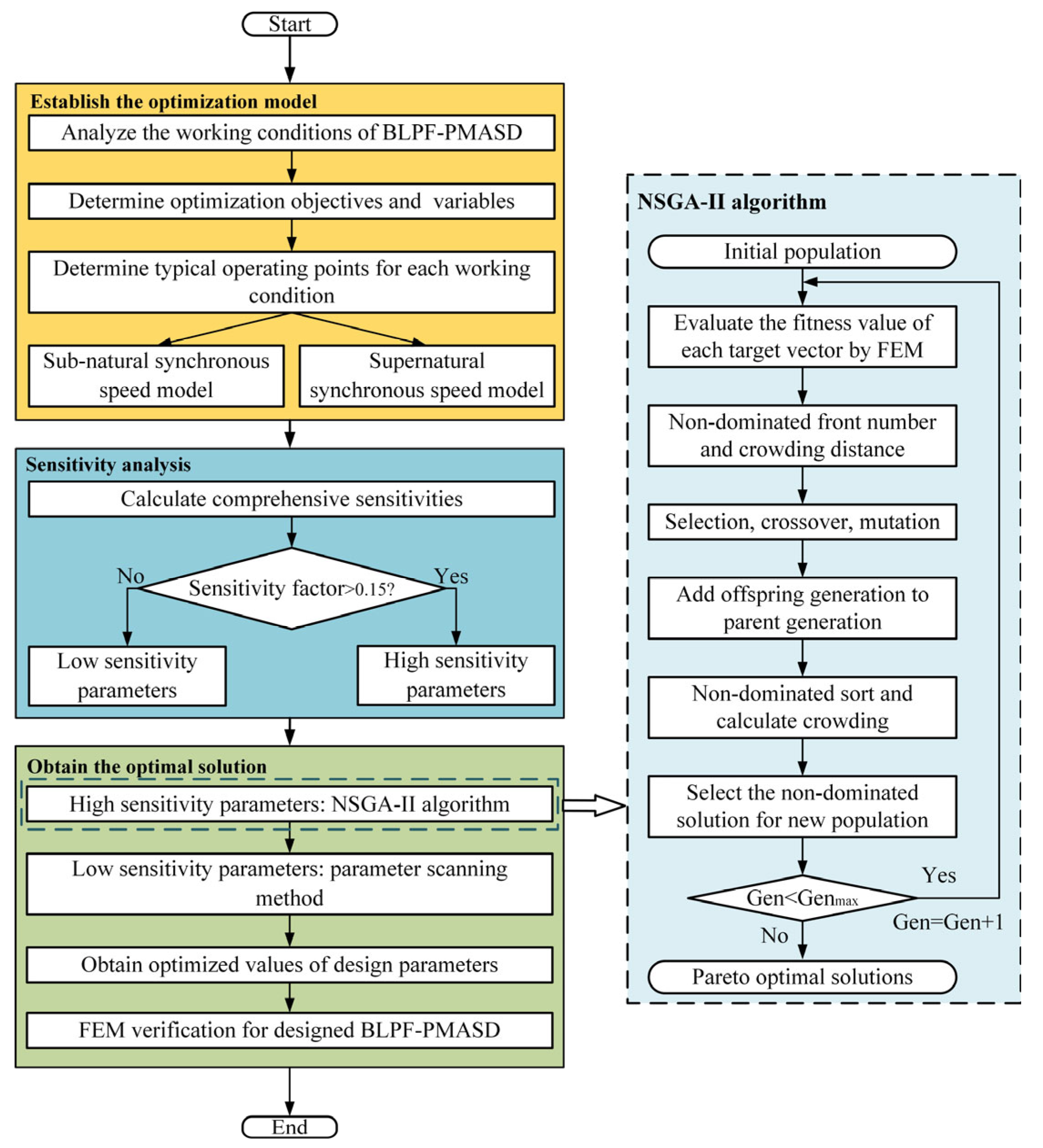
3. Multi-Working Conditions Optimization Design Method

Based on the above analysis, there are three markedly different working conditions for the proposed BLPF-PMASD. Among these, the natural synchronous speed is a specific rotational speed. In practical applications, however, the drive predominantly operates either below the natural synchronous speed, i.e., sub-natural synchronous speed range, or above it, i.e., super-natural synchronous speed range. To guarantee optimal performance in varying conditions, a multi-working conditions optimization design method is proposed. In this section, the detailed procedure of the proposed optimization method is explained by using a commonly employed industrial drive as an illustrative example, as depicted in Figure 3a. The basic parameters and technical specifications of the drive are summarized in Table 1. In order to enhance the drive system’s performance, the PM rotor employs a Halbach PM array. This configuration has the potential to generate stronger magnetic forces compared to conventional PM arrays, owing to their inherent self-shielding properties, thereby enhancing the utilization efficiency of PM materials. Due to the large number of pole pairs in the power subsystem, the inner winding adopts a fractional slot concentrated winding with shorter winding ends, which can reduce copper loss and improve efficiency. In contrast, the control subsystem has a relatively small number of pole pairs, and distributed windings are employed for both the stator and the outer winding to reduce the air-gap magnetic field harmonics in the control subsystem. The winding configuration of the inner and outer windings of the wound rotor is illustrated in Figure 3b. The inner and outer windings are connected in negative phase sequence; that is, phases U, V, and W of the inner winding are connected to phases U, W, and V of the outer winding, respectively.
The flowchart of the proposed optimization method is presented in Figure 4. Initially, representative working points are selected to reflect different working conditions. Specifically, 900 rpm and 1350 rpm are chosen as the representative working points for sub-natural synchronous speed and super-natural synchronous speed conditions, respectively. In practical applications, the working conditions of fan and pump loads can be analyzed to identify the most commonly used working point for establishing a corresponding model. Subsequently, the FEM models are established for the selected working points. After determining the optimization variables and objectives, a sensitivity analysis is conducted to highlight key parameter variables. For high-sensitivity variables, the NSGA-II algorithm is applied to achieve the optimal design scheme, while for low-sensitivity variables, a parameter scanning method is employed to determine their optimal values [23].

3.1. Determination of Variables and Objectives

Figure 5 depicts the primary design parameters of the proposed BLPF-PMASD, consisting of 14 optimization variables. Thereinto, Niwr, Nowr, and Nos represent the series turns per phase of inner, outer, and stator windings, respectively. The initial values and optimization ranges for all variables are listed in Table 2.
For a practical drive, efficiency and output torque performance are crucial evaluation metrics. Therefore, this study selects efficiency, average torque, and torque ripple as the optimization objectives. Additionally, to prevent potential issues caused by excessive temperature, the current densities of the windings are constrained in reasonable ranges. The optimization functions are defined as follows:
Function : y 1 x i = max η ¯ y 2 x i = max T ¯ ave y 3 x i = min T ¯ rip s . t   J c iw J cmax iw J c ow J cmax ow h iw h ˜ iw h ow h ˜ ow h os h ˜ os x i L x i x i U
where J c iw and J c ow represent the current densities of the inner and outer windings; J cmax iw and J cmax ow represent the maximum allowable current densities for the corresponding windings; x i L and x i U are the lower and upper limits of corresponding optimized variables; h iw , h ow and h os represent the slot depths for the inner, outer, and stator windings, calculated based on the design parameters; h ˜ iw , h ˜ ow and h ˜ os represent the given minimum slot depths for the three windings; this constraint helps address conflicts between optimization parameters and prevents the generation of infeasible solutions; η ¯ , T ¯ ave , and T ¯ rip are the weighted averages of the corresponding performance results, as follows:
η ¯ = λ sub η sub + λ sup η sup T ¯ ave = λ sub T ave sub + λ sup T ave sup T ¯ rip = λ sub T rip sub + λ sup T rip sup
where λ sub and λ sup are the weight factors for the different working conditions, respectively; η sub , η sup , T ave sub , T ave sup , T rip sub and T rip sup are the efficiencies, output average torque, and torque ripple of the drive at representative working points for sub-natural synchronous speed and super-natural synchronous speed conditions, respectively.
In this study, two FEM models were established for representative working points under both sub-natural synchronous speed and super-natural synchronous speed conditions. The electromagnetic performance of the drive was evaluated by using the FEM method, from which the output average torque, torque ripple, and efficiency were subsequently determined.
The torque ripple can be expressed as follows:
T rip = T t max T t min T avg × 100 %
where T t max and T t min denote the maximum and minimum torque values within the simulation period, respectively.
The efficiency is calculated based on the copper loss, iron loss, eddy current loss, and average torque obtained from the FEM. The calculation formulas for the drive efficiency under the two typical operating conditions, i.e., sub-natural synchronous speed and super-natural synchronous speed conditions, are as follows:
η sub = T pm _ avg sub ω pm P Cu sub P Core sub P pm sub T pm _ avg sub ω pm × 100 % η sup = T avg sup ω wr sup T avg sup ω wr sup + P Cu sup + P Core sup + P pm sup × 100 %
where T pm _ avg sub represents the average torque of the PM rotor at representative working point in sub-natural synchronous speed conditions; ω pm denotes the angular velocity of the PM rotor. P Cu sub , P Cu sup , P Core sub , P Core sup , P pm sub and P pm sup are copper loss, iron loss, and eddy current loss of the drive at representative working points for sub-natural synchronous speed and super-natural synchronous speed conditions, respectively; ω wr sup is the angular velocity of the wound rotor at representative working point in super-natural synchronous speed conditions.

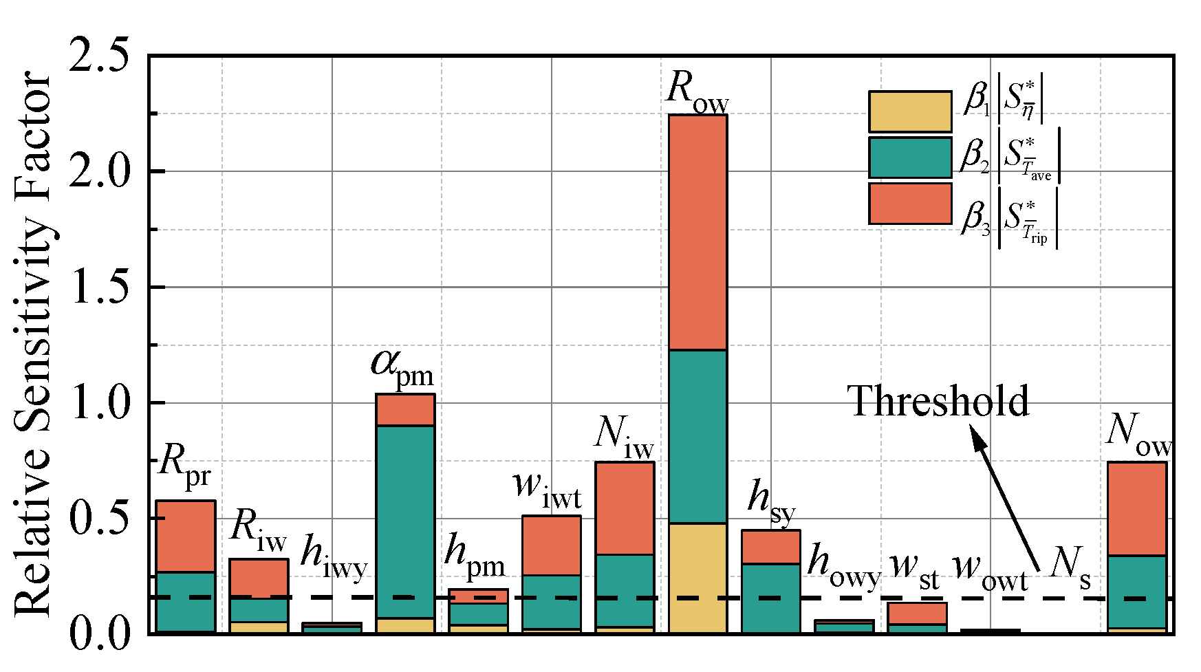
3.2. Sensitivity Analysis

Excessive variables can result in problems such as high computational complexity and difficulty in convergence. To address this, a sensitivity analysis is conducted on the variables to assess their significance. Parameters with low sensitivity are removed from the optimization set to reduce computational resource demands [24]. In order to compare the sensitivities of optimization parameters with different units, this study employs a relative sensitivity factor to evaluate the sensitivity of a single objective function with respect to a certain parameter [25]:
S x i = f x x i x = x 0 x i f x 0 = f x 0 ± x i f x 0 f x 0 / x i x 0
where x 0 is the initial value of the variable to be optimized. In multi-objective scenarios, some weight factors are introduced to comprehensively evaluate the sensitivities of design parameters across all objectives. The comprehensive relative sensitivity factor can be expressed as follows:
S com x i = β 1 S η ¯ x i + β 2 S T ¯ ave x i + β 3 S T ¯ rip x i
where S η ¯ x i , S T ¯ ave x i and S T ¯ rip x i represent the relative sensitivity factors of efficiency, average torque, and torque ripple, respectively; β 1 , β 2 and β 3 are the corresponding sensitive factor weights, satisfying β 1 + β 2 + β 3 = 1 . The weight factors are set to 0.4, 0.4, and 0.2, respectively. The sensitivity analysis results are illustrated in Figure 6. A threshold value of 0.15 is established for the comprehensive sensitivity factor, serving as the criterion for variable classification. Variables with sensitivity factors exceeding this threshold are identified as high-sensitivity parameters, whereas those below the threshold are categorized as low-sensitivity parameters.

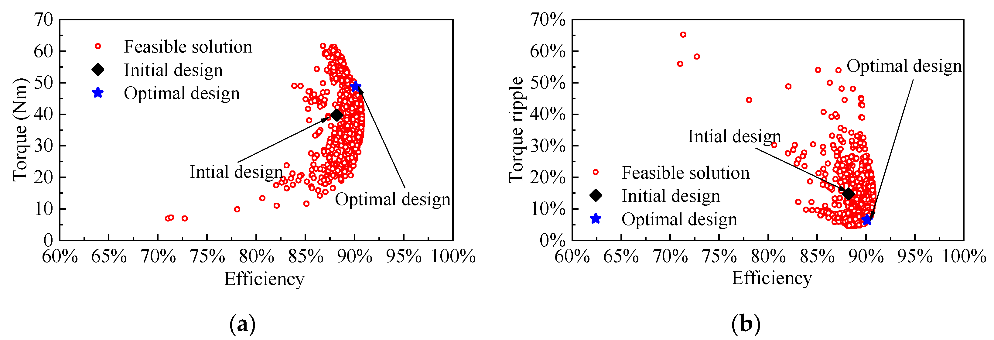
3.3. Optimization Results

In this study, the NSGA-II algorithm is utilized to optimize the drive. For the optimization configuration, the population size is set to 50, the maximum number of iterations is 50, the crossover probability is 0.9, and the mutation ratio of the DNA string is 0.05. The optimization results are shown in Figure 7. The Pareto set contains numerous and widely distributed solutions for the three optimization objectives, making it challenging to identify the optimal design solution solely based on the Pareto set. To address this issue, an objective evaluation index is established to objectively select the optimal design solution, taking into account the degree of emphasis placed on different objectives [26]. The evaluation index is defined as follows:
ξ = β 1 max y 1 y 1 j range y 1 + β 2 max y 2 y 2 j range y 2 + β 3 y 3 j min y 3 range y 3
where y 1 j , y 2 j , and y 3 j are the values of the objective functions in the Pareto set; max ( y ) and min ( y ) are the maximum and minimum values of the corresponding objective function in the Pareto set, respectively. A smaller evaluation index of a design scheme indicates better comprehensive performance. Hence, the design scheme with the minimum evaluation index is selected.
Table 3 presents a comparison of the electromagnetic performance between the initial design and the final optimal design schemes. As can be seen, the average torque, torque ripple, and efficiency of the final optimal design scheme are all superior to those of the initial design scheme. In addition, three other design points from the Pareto solution set are selected for comparison with the final optimal design scheme. Although these three design points outperform the final optimal design scheme in certain individual performance metrics, their overall performance is inferior to that of the final optimal design scheme.
After optimizing the high-sensitivity parameters using the NSGA-II algorithm, a parameter scanning is performed on the low-sensitivity parameters to determine the optimal values for all parameters. This scanning process is performed sequentially, following the descending order of the comprehensive sensitivity levels of the design variables. Each variable is optimized individually to identify its corresponding optimal value. The specific parameters of the optimal scheme are tabulated in Table 4.

4. Machine Performance Analysis

In this section, based on the FEM, some key electromagnetic characteristics of the optimal BLPF-PMASD are evaluated in detail to demonstrate the effectiveness and reasonability of the investigated drive.

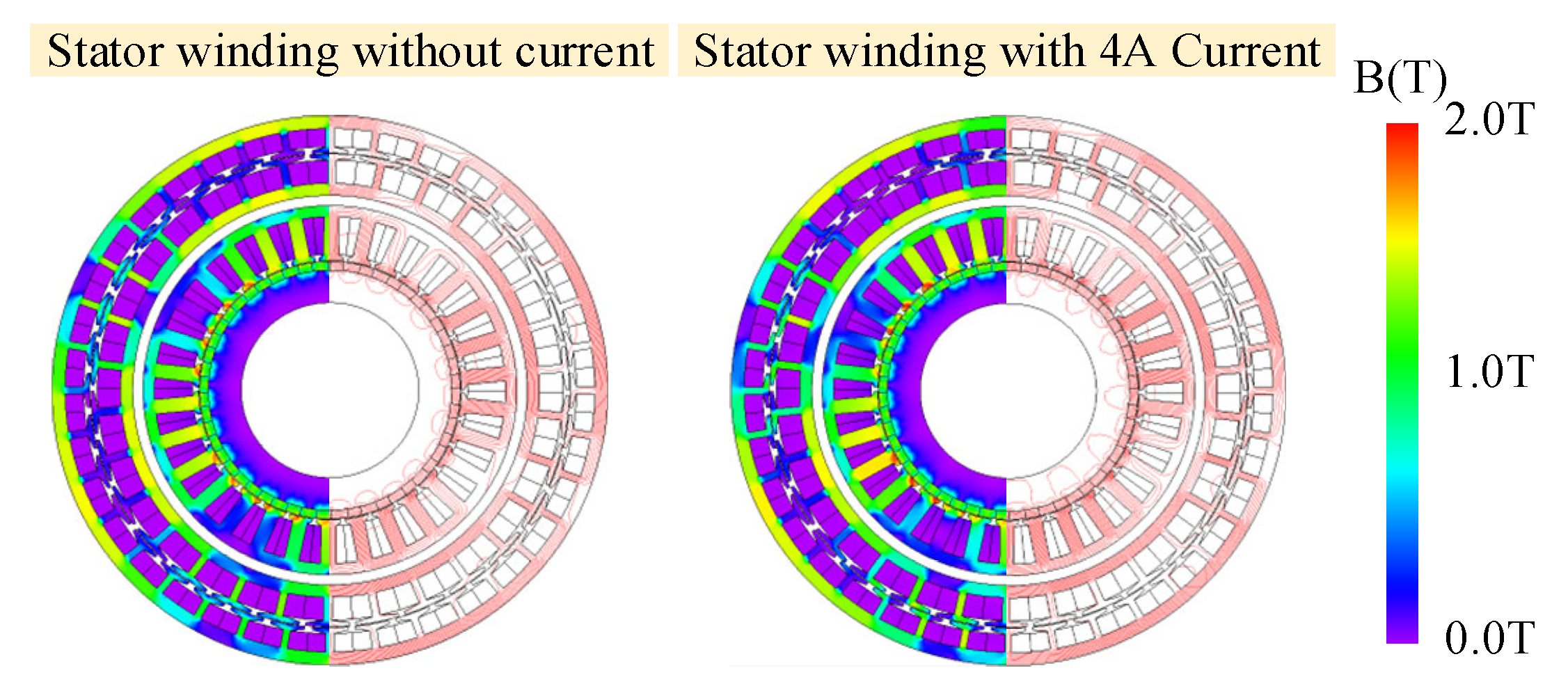
4.1. Magnetic Field Analysis

Taking a working condition with an output speed of 900 rpm as an example, the magnetic field distribution of the optimal drive is analyzed and compared under two scenarios: without current and with a 4A current in the stator winding. The corresponding results are respectively illustrated in Figure 8 and Figure 9. It can be observed that the magnetic field distributions of the drive undergo changes before and after the stator winding current is applied; however, these changes are relatively minor. This is because, after the stator winding current is applied, a load component that compensates for the stator magnetomotive force in the outer winding, thereby maintaining the main magnetic flux in the outer air gap essentially unchanged. In the power subsystem, the phase and amplitude of the inner winding current are altered after the stator winding current is applied. However, the magnetomotive force generated by the electric excitation in the inner winding remains relatively weak compared with that produced by the Halbach PM array. Consequently, the synthetic magnetic field in the inner air gap undergoes only minor variations. Unlike conventional drives, which adjust speed by varying the air gap magnetic flux density through changing the distance between the PM rotor and the conductor rotor, the proposed drive achieves speed regulation primarily by altering the magnitude and phase of the current in the stator winding.

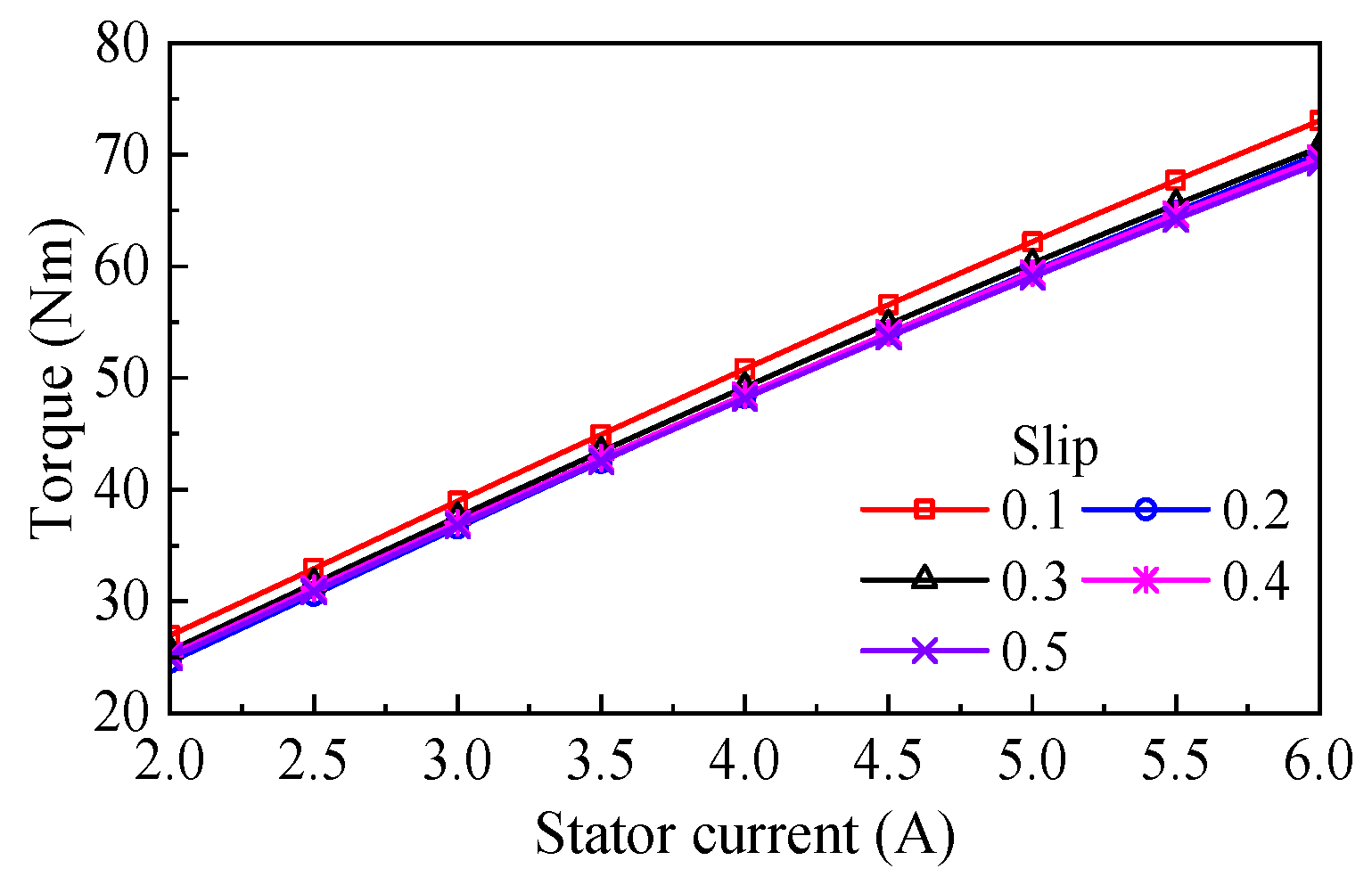
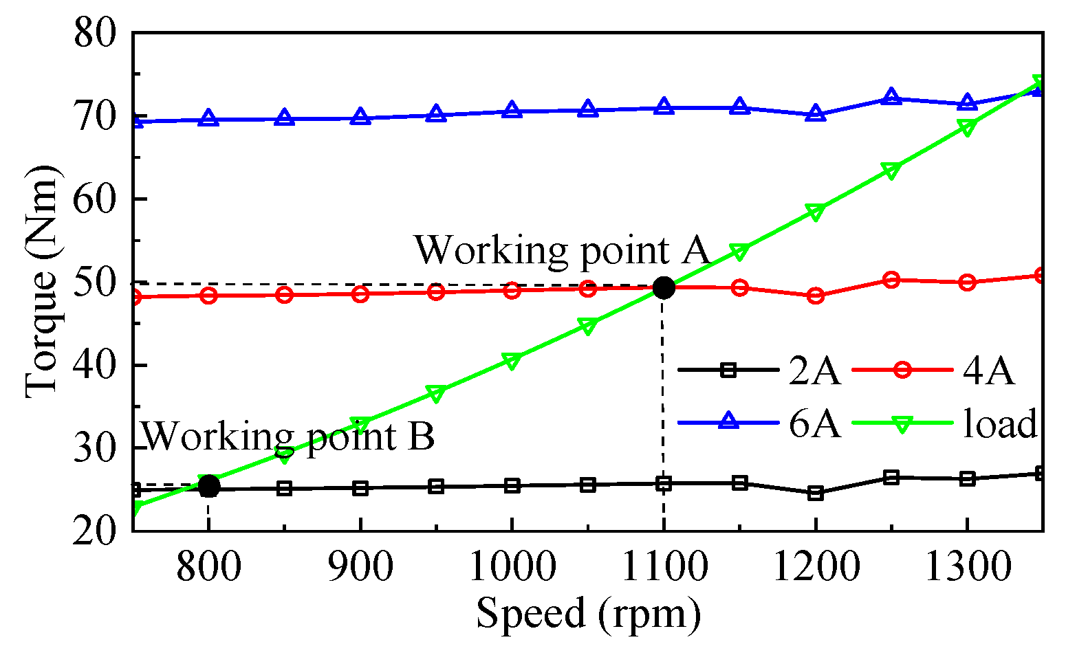
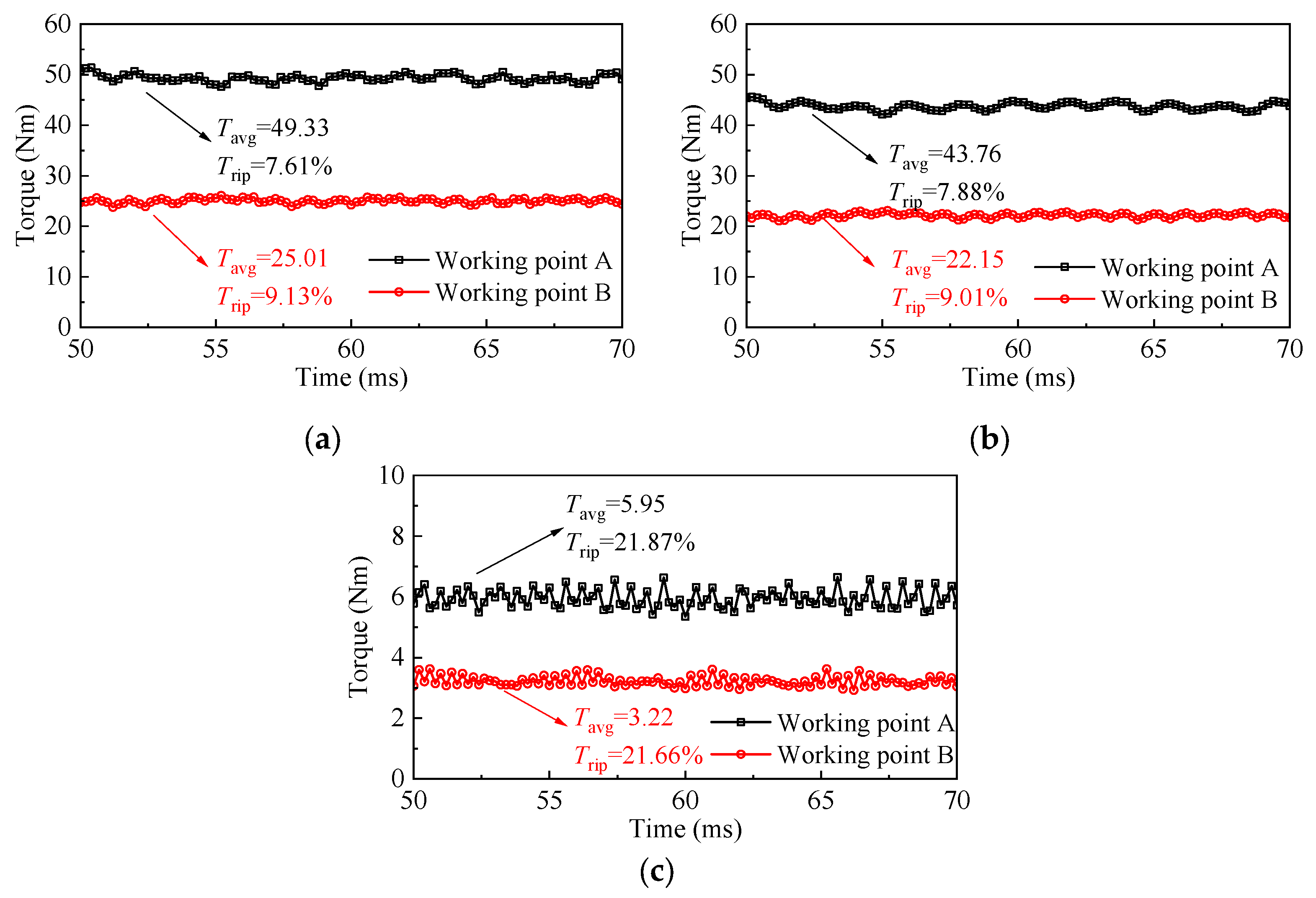
4.2. Torque Characteristics Analysis

The relationship between the torque and stator current (T-I characteristic) of the drive under different slip conditions is depicted in Figure 10. As the stator winding current increases, the output torque proportionally rises, with the slip exerting only a negligible influence on the torque output. This phenomenon can be attributed to the drive, which indirectly regulates the inner winding current by adjusting the stator winding current, thereby altering the torque output. Its weak dependence on the slip rate further enhances the drive’s stability during speed adjustment.
Figure 11 illustrates the speed adjustment characteristic curve of the drive. For fan and pump-type loads, their torques decrease steadily in a quadratic relationship as the load speed decreases. Assuming that the drive is operating at working point A, when the stator current of the drive is adjusted from 4A to 2A, the drive’s torque decreases from T A to T B , while the load torque temporarily remains stable at T A . The load torque exceeds the drive’s output torque, leading to a decrease in the load speed and a concurrent decrease in the load torque. As the output speed of the drive varies, the frequency of the stator winding current should be adjusted synchronously in accordance with the relationship defined in Equation (3). When the load speed drops to n B , the output torque of the drive equals the load torque, and the system reaches a new steady state. At this new operating point, the output power of the prime mover is also significantly reduced, achieving the purpose of speed adjustment and energy saving. If the drive receives an acceleration command, it can simply adjust the amplitude and frequency of the stator winding current to achieve the desired speed.
Figure 12a presents the output torque waveforms of the drive at working point A (800 rpm) and B (1100 rpm) in Figure 11. The results demonstrate that the torque ripples at both working points are below 10%, meeting the operational requirements for most fan and pump loads. Figure 12b and 12c display the torque waveforms of the power subsystem and the control subsystem, respectively. It can be observed that both subsystems contribute to the output torque simultaneously, with the power sub-system providing a greater torque contribution compared with the control subsystem. This is because the mechanical power of the control subsystem is derived from the conversion of a portion of the slip power by the power subsystem. Furthermore, the torque ripple in the control subsystem is relatively large. This is due to the magnetic field in the outer air gap being generated by both the stator winding and the outer winding, which introduces a significant number of harmonics. Nevertheless, since the torque produced by the control subsystem is relatively small, its impact on the overall output torque of the drive is minimal.

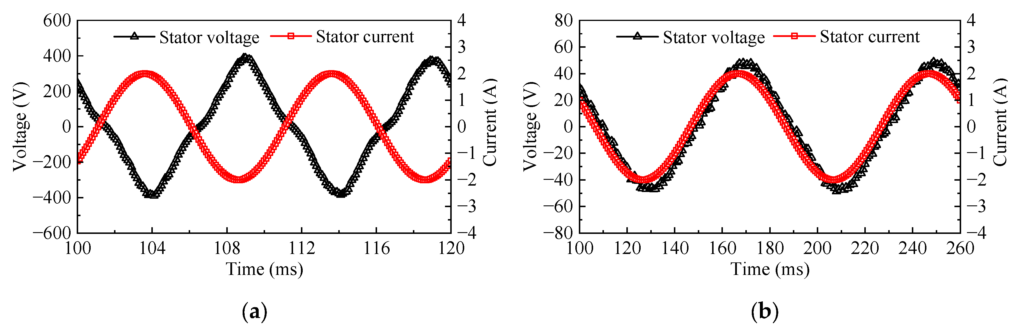
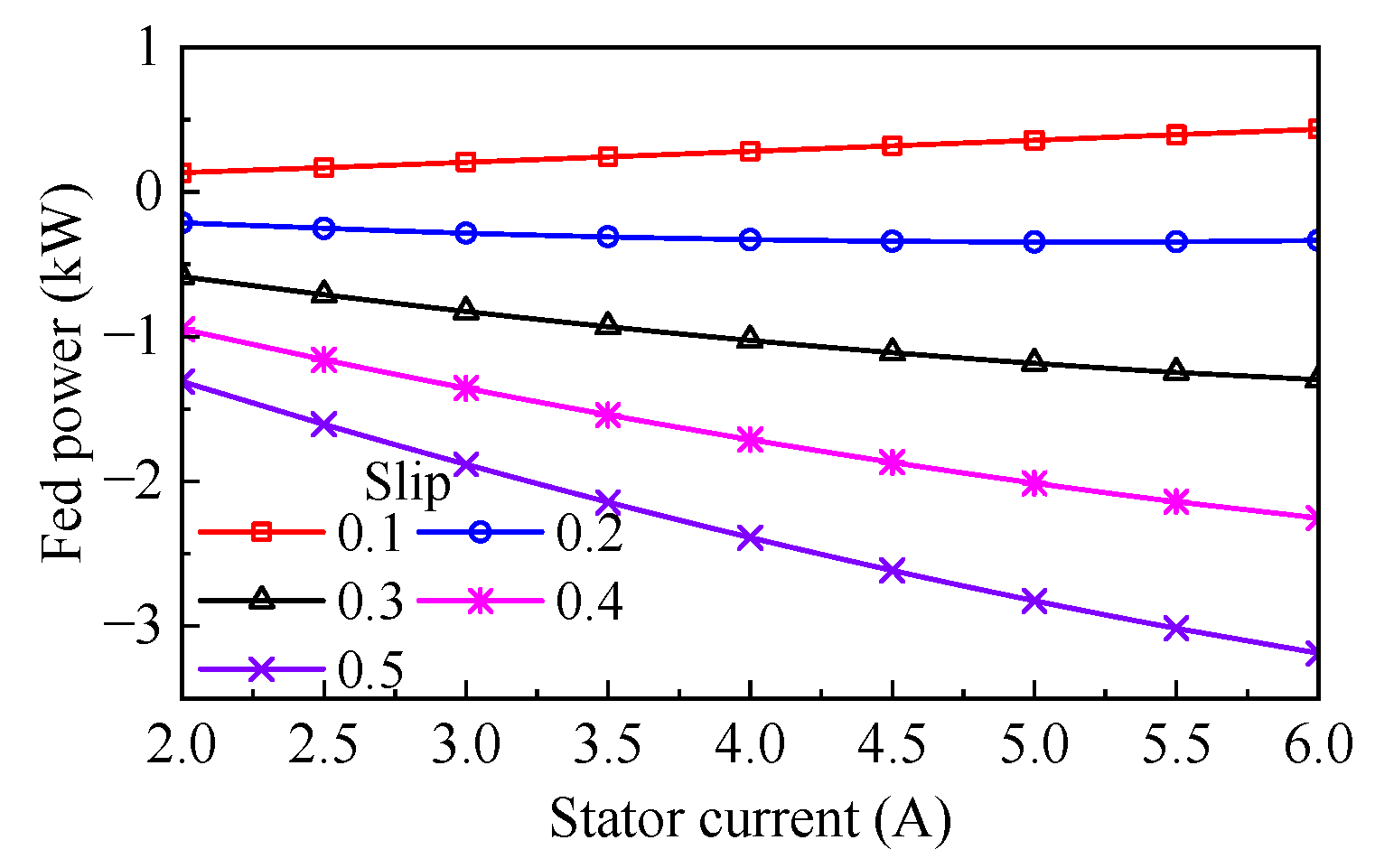
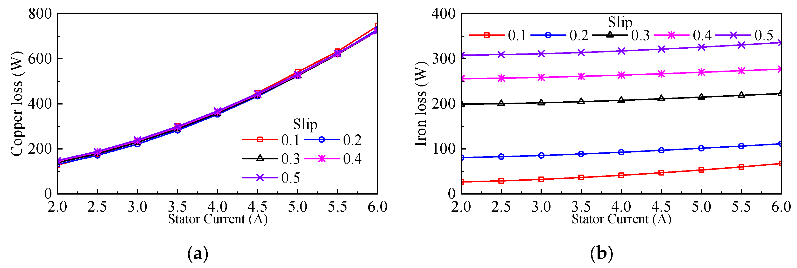
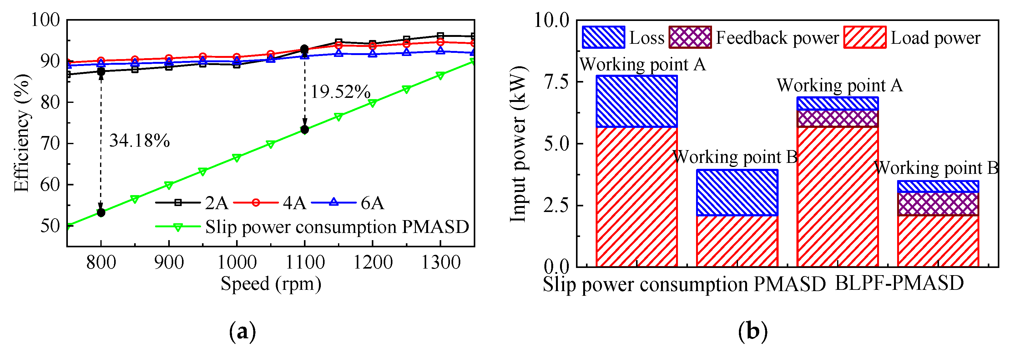
4.3. Power Flow and Efficiency Analysis

Figure 13 presents the voltage and current waveforms of the stator winding under sub-natural synchronous speed conditions (900 rpm) and super-natural synchronous speed conditions (1350 rpm). At sub-natural synchronous speeds, the phases of the voltage and current are reversed, indicating that the drive delivers power outward. Conversely, under super-natural synchronous speed conditions, the phases of the voltage and current are aligned, demonstrating that the drive absorbs electric power from the external circuit, i.e., the power grid. These results are consistent with the theoretical analysis.
Figure 14 illustrates the feedback power variation with respect to the current amplitude of the stator winding of the drive under different slip rates. It can be observed that the power feedback from the drive gradually diminishes as the slip ratio decreases. When operating above the natural synchronous speed, the drive absorbs electric power from the SPCU.
The curves of the copper and iron losses via the stator winding current of the drive under different slips are shown in Figure 15. It can be observed that the copper loss of the drive increases with the rise of the stator winding current and exhibits minimal correlation with the slip. Conversely, the iron loss of the drive increases as the slip rises, and the stator winding current has little effect on it.
Figure 16a presents an efficiency comparison between the proposed power feedback type drive and the conventional slip power dissipative one. [8]. The results show that the efficiencies of the designed drive under all working conditions are above 85%, far higher than traditional ones. Figure 16b illustrates the input powers of the two compared drives at working point A (800 rpm) and B (1100 rpm), marked in Figure 11. When driving the same mechanical load, the proposed drive demonstrates reduced input power requirements compared to conventional slip power consumption, PMASD, and possesses the capability to feedback most of the slip power into the grid, thereby reducing power losses and improving overall system efficiency. These findings confirm that the proposed drive can achieve the goal of energy conservation by adjusting the speed of the load with a higher efficiency.

5. Conclusions

In this paper, a BLPF-PMASD is proposed for achieving speed adjustment and energy-saving in the fan and pump transmission system, and optimized by using a multi-working conditions optimization design method. The main conclusions are summarized as follows:
(1)
By analyzing the magnetic field interactions and power flows between the main units, the speed regulation principle and power feedback mechanism of the drive are theoretically elucidated.
(2)
A multi-working conditions optimization method is proposed for the electro-magnetic design of the drive. The effectiveness of the optimization method was validated by comparing the electromagnetic performance of the initial and the optimal design schemes. The results indicate that, through optimization, the average torque is increased by 22.62%, the torque ripple is reduced by 56.11%, and the efficiency is improved by 2.17%.
(3)
The electromagnetic performance of the designed drive was validated through FEM. The results demonstrate that the proposed drive enables precise adjustment of the output speed and exhibits the advantages of low torque ripple and high efficiency, maintaining an efficiency greater than 85% under all operating conditions.
In future research, we will focus on developing an accurate thermal model for the BLPF-PMASD, analyzing the temperature field distribution under different operating conditions, and proposing appropriate cooling strategies.

Author Contributions

Conceptualization, X.Z. and H.L.; methodology, X.Z.; software, Y.L.; validation, X.Z., H.L. and Y.L.; formal analysis, J.W.; data curation, H.L.; writing—original draft preparation, X.Z. and Y.L.; writing—review and editing, H.L., J.W. and Q.W.; supervision, H.L.; funding acquisition, H.L. and Y.L. All authors have read and agreed to the published version of the manuscript.

Funding

This work was supported in part by the National Natural Science Foundation of China under Projects 52377040 and 52107048.

Data Availability Statement

The data presented in this study are available on request from the corresponding author.

Conflicts of Interest

The authors declare no conflicts of interest. The funders had no role in the design of this study, in the collection, analysis, or interpretation of data, in the writing of the manuscript, or in the decision to publish the results.

Abbreviations

The following abbreviations are used in this manuscript:
ACAlternating current
VFDsVariable frequency drives
ASDsAdjustable speed drives
PMPermanent magnet
PMASDPermanent magnet adjustable speed drive
PF-PMASDPower feedback permanent magnet adjustable speed drive
BLPF-PMASDBrushless power feedback permanent magnet adjustable speed drive
FEMFinite element method
SPCUSlip power control unit

Appendix A

The designed BLPF-PMASD can be regarded as a cascade of a PM synchronous generator (power subsystem) and a wound rotor induction machine (control subsystem). Firstly, dynamic models for both subsystems are established, and subsequently, the overall model of the drive is constructed based on their electrical interconnections.
The voltage equation of the power subsystem in the d-q frame is formulated as follows:
u rd p u rq p = R r p + s L rd p ω r p L rq p ω r p L rd p R r p + s L rq p i rd p i rq p + ω r p ψ f 0 1
where u rd p , u rq p , i rd p and i rq p are the inner winding voltages and currents of the d and q-axes, respectively; R r p is the phase resistance of the inner winding; s is the differential operator, s = d / d t ; L rd p and L rq p are the inner winding inductances of the d and q-axes, respectively; ψ f is the PM flux linkage of the PM rotor; ω r p the electrical angular velocity of the magnetic field produced by the inner winding, ω r p = p p ω pm ω wr , wherein ω pm and ω wr are the mechanical angular velocities of the PM rotor and the wound rotor, respectively.
The torque provided by the power subsystem to the wound rotor is given by the following:
T wrp = 1.5   p p ψ f i rq p + 1.5   p p i rd p i rq p L rd p L rq p
The voltage equation of the control subsystem in the d-q frame is formulated as follows:
u sd u sq u rd c u rq c = R s + s L s ω c L s s L mc ω c L mc ω c L s R s + s L s ω c L mc s L mc s L mc ω r c L mc R r c + s L r c ω r c L r c ω r c L mc s L mc ω r c L r c R r c + s L r c i sd i sq i rd c i rq c
where u sd , u sq , u rd c and u rq c are the stator and outer winding voltages of the d and q-axes, respectively; i sd , i sq , i rd c and i rq c are the stator and outer winding currents of the d and q-axes, respectively; R s and R r c and are the phase resistance of the stator and outer winding, respectively; L s and L r c are the self-inductances of the stator winding and the outer winding, respectively; L mc the mutual inductance between the stator winding and the outer winding; ω r c and ω c are the electrical angular velocity of the magnetic field produced by the outer winding and stator winding, ω r c = p p ω wr ω pm , ω c = p p + p c ω wr p p ω pm .
The torque provided by the control subsystem to the wound rotor is given by the following:
T wrc = 1.5   p c L ms i sq i rd c i sd i rq c
The inner and the outer winding are connected in a negative phase sequence, resulting in the following relationship between voltage and current:
u rd = u rd p = u rd c u rq = u rq p = u rq c i rd = i rd p = i rd c i rq = i rq p = i rq c
Accordingly, the voltage equation of the drive can be expressed as follows:
u sd u sq 0 0 = R s + s L s ω c L s s L mc ω c L mc ω c L s R s + s L s ω c L mc s L mc s L mc ω r p L mc R r + s L rd ω r p L rq ω r p L mc s L mc ω r p L rd R r + s L rq i sd i sq i rd i rq + ω r p ψ f 0 0 0 1
where R r is the total resistance of the wound rotor, R r = R r p + R r c ; L rd and L rq are the total d-axis and q-axis inductances of the wound rotor, respectively, L rd = L r c + L rd p , L rq = L r c + L rq p .
The total output torque of the drive is as follows:
T wr = T wrp + T wrc = 1.5   p p i rq ψ f + 1.5   p p i rd i rq L rd L rq + 1.5   p c L mc i sq i rd + i sd i rq
The mechanical motion equation of the designed drive is given by the following:
J d ω wr d t = T wr T L
where J is the combined inertia moment of the drive and the load; ω wr is the angular velocity of the wound rotor; T L is the load torque.

References

  1. Ferreira, F.J.T.E.; Fong, J.A.C.; Almeida, A.T.d. Ecoanalysis of Variable-Speed Drives for Flow Regulation in Pumping Systems. IEEE Trans. Ind. Electron. 2011, 58, 2117–2125. [Google Scholar] [CrossRef]
  2. Wang, F.; Stelson, K.A. An Efficient Fan Drive System Based on a Novel Hydraulic Transmission. IEEE/ASME Trans. Mechatron. 2015, 20, 2234–2241. [Google Scholar] [CrossRef]
  3. Saxena, J.; Choudhury, B.K.; Agra, K.M. Innovations in Variable Frequency Drives and its Implication in Reducing Carbon Footprint. In Encyclopedia of Renewable and Sustainable Materials; Hashmi, S., Choudhury, I.A., Eds.; Elsevier: Oxford, UK, 2020; pp. 534–544. [Google Scholar] [CrossRef]
  4. Giannoutsos, S.V.; Manias, S.N. A Systematic Power-Quality Assessment and Harmonic Filter Design Methodology for Variable-Frequency Drive Application in Marine Vessels. IEEE Trans. Ind. Appl. 2015, 51, 1909–1919. [Google Scholar] [CrossRef]
  5. Nassif, A.B. Assessing the Impact of Harmonics and Interharmonics of Top and Mudpump Variable Frequency Drives in Drilling Rigs. IEEE Trans. Ind. Appl. 2019, 55, 5574–5583. [Google Scholar] [CrossRef]
  6. Moradi, A.; Zare, F.; Kumar, D.; Yaghoobi, J.; Sharma, R.; Kroese, D. Current Harmonics Generated by Multiple Adjustable-Speed Drives in Distribution Networks in the Frequency Range of 2–9 kHz. IEEE Trans. Ind. Appl. 2022, 58, 4744–4757. [Google Scholar] [CrossRef]
  7. Alshammari, S.; Lazari, P.; Atallah, K. Comparison of Eddy Current Coupling Topologies for High Efficiency Mechanical Power Transmission. IEEE Trans. Energy Convers. 2023, 38, 982–992. [Google Scholar] [CrossRef]
  8. Wang, J.; Zhu, J. A Simple Method for Performance Prediction of Permanent Magnet Eddy Current Couplings Using a New Magnetic Equivalent Circuit Model. IEEE Trans. Ind. Electron. 2018, 65, 2487–2495. [Google Scholar] [CrossRef]
  9. Wang, J.X.; Wang, D.Z.; Wang, S.H.; Tong, T.L.; Sun, L.S.; Li, W.H.; Kong, D.S.; Hua, Z.; Sun, G.F. A Review of Recent Developments in Permanent Magnet Eddy Current Couplers Technology. Actuators 2023, 12, 277. [Google Scholar] [CrossRef]
  10. Bronzeri, R.B.; Chabu, I.E. Concept Validation of an Automotive Variable Flow Water Pump With an Eddy Current Magnetic Coupling. IEEE Trans. Transp. Electrif. 2021, 7, 2939–2950. [Google Scholar] [CrossRef]
  11. Lubin, T.; Rezzoug, A. 3-D Analytical Model for Axial-Flux Eddy-Current Couplings and Brakes Under Steady-State Conditions. IEEE Trans. Magn. 2015, 51, 8203712. [Google Scholar] [CrossRef]
  12. Atallah, K.; Wang, J. A Brushless Permanent Magnet Machine With Integrated Differential. IEEE Trans. Magn. 2011, 47, 4246–4249. [Google Scholar] [CrossRef]
  13. Li, Y.; Lin, H.; Yang, H. A Novel Squirrel-Cage Rotor Permanent Magnet Adjustable Speed Drive With a Non-Rotary Mechanical Flux Adjuster. IEEE Trans. Energy Convers. 2021, 36, 1036–1044. [Google Scholar] [CrossRef]
  14. Wang, J. A Generic 3-D Analytical Model of Permanent Magnet Eddy-Current Couplings Using a Magnetic Vector Potential Formulation. IEEE Trans. Ind. Electron. 2022, 69, 663–672. [Google Scholar] [CrossRef]
  15. Aberoomand, V.; Mirsalim, M.; Fesharakifard, R. Design Optimization of Double-Sided Permanent-Magnet Axial Eddy-Current Couplers for Use in Dynamic Applications. IEEE Trans. Energy Convers. 2019, 34, 909–920. [Google Scholar] [CrossRef]
  16. Xikang, C.; Wei, L.; Yang, Z.; Sitong, L.; Weiqi, L. A Concise Transmitted Torque Calculation Method for Pre-Design of Axial Permanent Magnetic Coupler. IEEE Trans. Energy Convers. 2020, 35, 938–947. [Google Scholar] [CrossRef]
  17. Jin, P.; Tian, Y.; Lu, Y.; Guo, Y.; Lei, G.; Zhu, J. 3-D Analytical Magnetic Field Analysis of the Eddy Current Coupling With Halbach Magnets. IEEE Trans. Magn. 2020, 56, 7501904. [Google Scholar] [CrossRef]
  18. Kong, D.S.; Wang, D.Z.; Ni, Y.L.; Song, K.L.; Qi, Y.F.; Li, Y.M. Analytical Analysis of a Novel Flux Adjustable Permanent Magnet Eddy Current Coupling with Double-Sided Conductor. Actuators 2023, 12, 105. [Google Scholar] [CrossRef]
  19. Wang, D.Z.; Niu, B.W.; Pan, P.Y.; Sun, G.F. Multi-Objective Optimization Design of Permanent Magnet Eddy Current Coupler Based on SCG-BP Neural Network Modeling and the ONDX-NSGA-II Algorithm. Actuators 2023, 12, 367. [Google Scholar] [CrossRef]
  20. Wang, J.X.; Wang, D.Z.; Wang, S.H.; Li, W.H. Modeling of Permanent Magnet Eddy-Current Coupler Based on Unsupervised Physics-Informed Radial-Based Function Neural Networks. IEEE Trans. Magn. 2025, 61, 4900210. [Google Scholar] [CrossRef]
  21. Wu, Y.L.; Wang, X.C.; Jiang, H.R.; Li, W.H.; Zhang, X.J.; Zhang, D.; Zhou, D.F.; Zhang, G.M. Study on Magnetic Coupler With Clutch Function Based on Magnetization and Demagnetization Properties of Superconducting Bulks. IEEE Trans. Appl. Supercond. 2025, 35, 6800405. [Google Scholar] [CrossRef]
  22. Li, Y.; Lin, H.; Huang, H.; Chen, C.; Yang, H. Analysis and Performance Evaluation of an Efficient Power-Fed Permanent Magnet Adjustable Speed Drive. IEEE Trans. Ind. Electron. 2019, 66, 784–794. [Google Scholar] [CrossRef]
  23. Zhu, X.; Fan, D.; Mo, L.; Chen, Y.; Quan, L. Multiobjective Optimization Design of a Double-Rotor Flux-Switching Permanent Magnet Machine Considering Multimode Operation. IEEE Trans. Ind. Electron. 2019, 66, 641–653. [Google Scholar] [CrossRef]
  24. Meng, Y.; Fang, S.; Pan, Z.; Liu, W.; Qin, L. Machine Learning Technique Based Multi-Level Optimization Design of a Dual-Stator Flux Modulated Machine With Dual-PM Excitation. IEEE Trans. Transp. Electrif. 2023, 9, 2606–2617. [Google Scholar] [CrossRef]
  25. Zang, B.; Chen, Y. Multiobjective Optimization and Multiphysics Design of a 5 MW High-Speed IPMSM Used in FESS Based on NSGA-II. IEEE Trans. Energy Convers. 2023, 38, 813–824. [Google Scholar] [CrossRef]
  26. Wang, C.; Zhang, Z.; Han, J. Multiobjective Optimization of High Power Density Outer Rotor PM Starter Generator Considering Electromagnetic and Temperature Characteristics. IEEE Trans. Ind. Electron. 2024, 71, 8339–8350. [Google Scholar] [CrossRef]
Figure 1. Topology and winding configuration of BLPF-PMASD: (a) Topology and (b) winding configuration.
Actuators 14 00241 g001
Figure 2. Power flow of the BLPF-PMASD.
Actuators 14 00241 g002
Figure 3. Structural model of BLPF-PMASD: (a) Section views and 3-D models, and (b) winding configurations of wound rotor.
Actuators 14 00241 g003
Figure 4. Multi-working conditions optimization design flowchart.
Actuators 14 00241 g004
Figure 5. Parametric model of BLPF-PMASD.
Actuators 14 00241 g005
Figure 6. Result of the sensitivity analysis.
Actuators 14 00241 g006
Figure 7. Optimization results: (a) Efficiency against torque and (b) efficiency against torque ripple.
Actuators 14 00241 g007
Figure 8. Magnetic field distribution of BLPF-PMASD.
Actuators 14 00241 g008
Figure 9. Air gap flux densities of BLPF-PMASD: (a) Inner air gap and (b) outer air gap.
Actuators 14 00241 g009
Figure 10. T-I characteristic under different slips.
Actuators 14 00241 g010
Figure 11. Speed adjustment characteristics.
Actuators 14 00241 g011
Figure 12. Torque waveforms: (a) Total output torque, (b) torque generated by the power subsystem, and (c) torque generated by the control subsystem.
Actuators 14 00241 g012
Figure 13. Stator current and voltage: (a) 900 rpm and (b) 1350 rpm.
Actuators 14 00241 g013
Figure 14. Fed power of the drive under different slips.
Actuators 14 00241 g014
Figure 15. Losses of the drive under different slips: (a) Copper loss, and (b) iron loss.
Actuators 14 00241 g015
Figure 16. Power characteristics: (a) Efficiency, and (b) input power.
Actuators 14 00241 g016
Table 1. Technical requirements and basic parameters of the drive.
ItemValue
Rated load power10 kW
Driving speed of the prime mover1500 rpm
Range of slip adjustment0.1–0.5
Stator outer radius135 mm
Active axis length90 mm
Power subsystem pole pairs13
Control subsystem pole pairs2
Natural synchronous speed1300 rpm
Number of stator slots/pitch36/8
Number of inter wound rotor slots/pitch30/1
Number of outer wound rotor slots/pitch30/6
Table 2. Initial values and ranges of design variables.
VariableInitialRangeVariableInitialRange
Rpr (mm)5040–70Row (mm)110100–120
Riw (mm)8575–100hsy (mm)64–8
hiwy (mm)64–8howy (mm)64–8
αpm (deg)95–11wst (mm)42–6
hpm (mm)42–6wowt (mm)42–6
wiwt (mm)64–8Ns300120–480
Niw300150–450Now250150–350
Table 3. Electromagnetic performance comparison.
ItemInitial
Design
Pareto
Point 1
Pareto
Point 2
Pareto
Point 3
Optimal
Design
Torque (Nm)39.7349.5947.8539.4848.72
Torque ripple (%)14.787.575.5113.216.49
Efficiency (%)88.2089.8189.9390.7690.11
Evaluation index ( ξ )0.2460.1170.1210.1910.114
Table 4. Optimal values of design variables.
VariableValueVariableValueVariableValue
Rpr (mm)59.0wiwt (mm)7.1wowt (mm)3.8
Riw (mm)90.7Row (mm)116.1Ns300
hiwy (mm)5.5hsy (mm)6.4Now200
αpm (deg)6.4howy (mm)6.0Niw390
hpm (mm)4.2wst (mm)3.5
Disclaimer/Publisher’s Note: The statements, opinions and data contained in all publications are solely those of the individual author(s) and contributor(s) and not of MDPI and/or the editor(s). MDPI and/or the editor(s) disclaim responsibility for any injury to people or property resulting from any ideas, methods, instructions or products referred to in the content.

