Abstract
Aiming at the control challenges of strong nonlinearity, time-varying parameters and multi-channel disturbance coupling in multi-address laser communication networking caused by the common inertial reference of multi-directional mirror strapdown stabilized platforms, a genetic algorithm-optimized active disturbance rejection control (GA-ADRC) method is proposed. By constructing a distributed active disturbance rejection control (ADRC) architecture and using genetic algorithms to globally and collaboratively optimize the observer gain and control parameters, the disturbance suppression and dynamic decoupling of multi-variable systems are effectively achieved. Experimental results show that under 0.1–0.3 Hz base disturbances, this method improves the line of sight (LOS) stabilization accuracy by 28–32%, with a standard deviation better than 14 μrad, significantly outperforming traditional PID control. This research not only provides a high-accuracy control solution that does not rely on precise models for multi-LOS cooperative stabilization but also offers a generalizable theoretical and practical framework for the intelligent control of complex optoelectronic systems.
1. Introduction
Space laser communication technology boasts three prominent advantages: high transmission rate, strong anti-interference capability, and low interception probability. These advantages have made it a key technology direction for building the next-generation space-based and airborne communication networks [1,2,3,4]. This has led to an increasing demand for laser communication terminals that need to meet four core requirements: lightweight, low-cost, high-reliability, and support for multi-node dynamic interconnection [5,6].
In terms of the stabilization and control architecture, strapdown stabilization technology, by eliminating the mechanical stabilization stage in the traditional coarse-fine compound stabilization platform, significantly reduces the volume, weight, and complexity of the optical terminal, making it more suitable for multi-node cooperative networking applications [7,8,9].
However, current laser communication systems still mainly operate in point-to-point transmission mode [10,11]. To achieve true multi-node dynamic networking, we have proposed a new strapdown stabilization scheme of “single inertial unit sharing + independent control of multiple pointing mirrors” [12]. This scheme installs a common inertial measurement unit (IMU) on the base to provide unified base angular motion perception for multiple pointing mirrors and then stabilizes and aims each LOS through independent controllers. Compared with the traditional “one gyroscope per mirror” scheme, this structure significantly reduces the system’s weight, cost, and power consumption. The kinematic modeling of the multi-pointing-mirror system builds upon our previous work detailed in [13,14,15]. However, due to the complex kinematic and dynamic coupling between the gyroscope and each pointing mirror, the system exhibits strong nonlinearity, time-varying parameters, and multi-channel interference, making traditional linear control methods (such as PID) difficult to achieve high-accuracy and high-robustness stabilization control.
To address the control challenges of such multi-variable and strongly coupled systems, Active Disturbance Rejection Control (ADRC) shows significant potential. This framework can achieve high-performance control with only a relatively rough system model, especially suitable for complex controlled objects like multi-pointing-mirror systems [16,17,18]. However, the performance of ADRC is critically dependent on the tuning of its multiple parameters, particularly the observation gain of the Extended State Observer (ESO) and the control law coefficients. Traditional tuning methods, which often rely on empirical trial and error, are not only time-consuming but also struggle to ensure optimal coordination across multiple control loops. This limitation constitutes a major bottleneck for the widespread application of ADRC in high-dimensional systems [19,20,21].
Intelligent optimization algorithms, particularly Genetic Algorithm (GA), offer an effective solution to the parameter tuning problem of ADRC. As a global search method based on natural selection and genetic mechanisms, GA is particularly suitable for handling complex, nonlinear, and high-dimensional parameter optimization problems [22,23]. In recent years, the integration of GA and ADRC has made positive progress: Ge et al. used GA to optimize the parameters of single-variable ADRC offline, effectively improving control accuracy [24]; Zhou et al. further extended it to multi-input multi-output (MIMO) systems, demonstrating the effectiveness of GA in solving the collaborative optimization of multiple-loop ADRC parameters [25].
The performance bottleneck of the multi-pointing-mirror laser communication terminal mainly stems from the insufficient accuracy of multi-LOS coordinated control under complex disturbances. This paper proposes a comprehensive solution of self-adaptive disturbance rejection control optimized by genetic algorithm. This solution aims to achieve deep coordination in three aspects: the hardware foundation of the strapdown stabilization structure, the real-time disturbance estimation and compensation of ADRC, and the global optimization of controller parameters by GA. This solution solves the problems of parameter tuning and coordinated control in multi-LOS stabilization, laying the theoretical and practical foundation for high-accuracy control.
2. Architecture of Multi-Access Laser Communication Strapdown Stabilization Control System
Basic Principles of Laser Communication Networking
Space laser communication networking aims to construct a dynamic high-bandwidth communication network composed of multiple nodes, such as satellites and aircraft. Its core objective is to enable rapid, precise, and stable information transmission via optical links between nodes. Unlike traditional point-to-point communication, networking requires a single optical terminal to possess multi-address capability—the ability to simultaneously establish and maintain stable links with multiple terminals in different directions.
Figure 1 depicts a topological network comprising geostationary orbit (GEO) satellites, low Earth orbit (LEO) satellites, a space station, an aerospace aircraft and ground stations. The nodes are interconnected via dense laser links, forming a highly redundant and dynamic laser communication infrastructure.
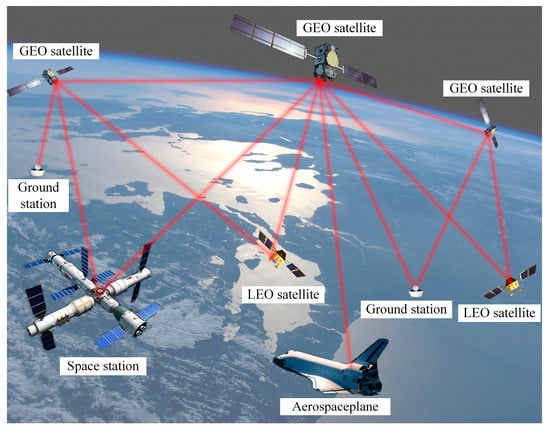
Figure 1.
Schematic diagram of spatial laser communication networking.
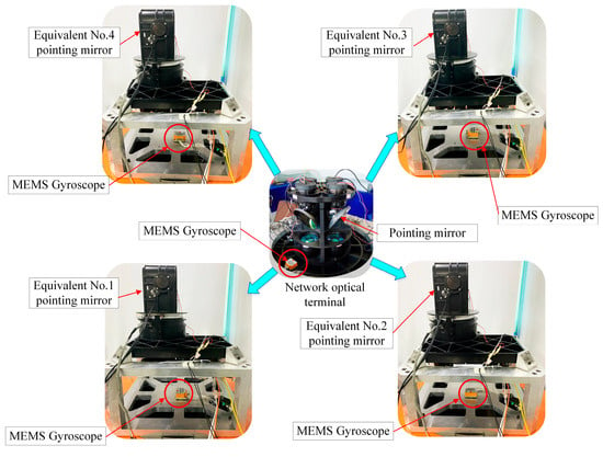
The core challenge in achieving multi-node laser communication lies in the high-accuracy synchronous stability of multiple LOS: each communication link needs to point to an independent LOS, and all pointing mirrors share the same base platform. This paper proposes a control system scheme based on a shared single inertial reference and independent multiple control loops, with its core architecture detailed in Figure 2.
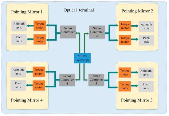
Figure 2.
Schematic diagram of the system composition of the multi-pointing-mirror optical terminal.
A micro electromechanical system (MEMS) gyroscope is fixed at the center of the base platform as a shared inertial measurement unit, which measures the base’s multi-degree-of-freedom angular vibrations and disturbances in real time. The measured disturbance data are simultaneously shared with four independent servo controllers.
Each of the four pointing mirrors (numbered 1–4) is equipped with both azimuth and elevation axes. Each mirror is driven by a dedicated torque motor under closed-loop control from an individual servo controller.
However, disturbances, which arise from the platform’s own motion and the spatial environment propagate through the structural framework to the pointing mirrors, ultimately leading to deviation of the LOS and potential communication interruption.
To address this issue, the controller processes two critical inputs: the base disturbance data and the fine-tracking error signal. These two inputs are fed into an ADRC to generate a real-time compensation command. This command then drives the torque motor to counteract the impact of base disturbances on the pointing accuracy of the LOS.
3. Design of Active Disturbance Rejection Controller
Traditional PID control relies on an accurate mathematical model to function effectively. However, this reliance results in inherent limitations in robustness. These limitations become particularly evident when the system involves strong coupling, unmodeled dynamics, and external disturbances. Other advanced controllers have inherent limitations in this scenario:
H∞ control: Requires establishing an accurate system model and disturbance model, but the strong nonlinearity and multi-channel coupling of the system in this paper make it extremely difficult to establish an accurate model. Moreover, the weight matrix design of the H∞ controller relies on experience, and the robustness improvement is limited.
LQR control: Based on the linear quadratic optimal criterion, it is sensitive to system nonlinearity and parameter time-variation, and cannot directly handle external disturbances, requiring an additional disturbance observer to be designed, which increases system complexity.
MPC control: Needs to solve quadratic programming problems online, with a computational complexity of O(N3) (N is the prediction horizon). For the embedded platform (STM32H743ZI), when N = 10, the single calculation time is ≥5 ms, which cannot meet the real-time control requirement of 1 ms.
Compared with the above controllers, GA-ADRC does not require an accurate model, and real-time estimates and compensates for all disturbances (including model errors, nonlinearities, and external disturbances) through ESO. In addition, GA optimizes multi-channel parameters offline, with a computational complexity of only O(1), balancing robustness, real-time performance, and engineering feasibility. Citing the theoretical comparison results of references [26], in multi-variable strongly coupled disturbance systems, the robustness indicators (such as gain margin and phase margin) of ADRC-based methods are superior to H∞ and LQR, and the computational efficiency is much higher than MPC.
To fulfill the demand for high-accuracy stability in multi-pointing-mirror systems under complex disturbances, a distributed architecture based on ADRC is employed. Each local controller utilizes measurements from the Inertial Measurement Unit (IMU) and encoder feedback. It then synthesizes the control signal by integrating two components: linear state feedback and feedforward compensation. The feedforward compensation is derived from the real-time disturbance estimation provided by the ADRC.
This synthesis generates control signals that proactively counteract disturbances, effectively suppressing their impact before they affect the system output.
3.1. Basic Principles
ADRC is a modern control strategy designed to achieve robust performance through real-time estimation and compensation for both internal and external disturbances. Its core concept involves treating various uncertainties, which include model inaccuracies, external disturbances, and system nonlinearities, as a generalized total disturbance. This total disturbance is estimated online by an ESO and subsequently canceled via feedforward compensation. A key advantage of this approach is that it eliminates the need for intricate system modeling.
In multi-pointing-mirror systems, ADRC stabilizes the LOS through a three-step closed-loop process. This process comprises: (1) signal preprocessing, (2) disturbance estimation, and (3) feedback compensation. A key advantage of this approach is that it eliminates the need for intricate system modeling. The workflow is as follows:
Signal Preprocessing via Tracking Differentiator (TD): The TD receives the target attitude command. Its function is to generate a smoothed reference trajectory and its differential estimate. This is achieved by adjusting the speed regulation factor and the integration step size based on the fastest control synthesis function. Concurrently, a filtering factor is used to suppress overshoot during the transient process. ESO: The ESO, designed for higher-order systems, combines the mirror’s actual output and control input. Using a nonlinear function to compute the estimation error, it continuously estimates the system states and the total disturbance. Feedback Compensation via Nonlinear State Error Feedback (NSEF): The NSEF module calculates a preliminary control signal using the outputs from the TD and the ESO. The final control command is derived by superimposing an inverted disturbance value (adjusted by a compensation parameter) onto this baseline signal, which then drives the mirror actuator.
Prior to controller activation, a genetic algorithm optimizes the parameters across all modules to decouple multiple control channels. This enables the system to proactively counteract disturbances before they affect the mirror, thereby ensuring high-accuracy stabilization of the LOS.
3.2. Tracking Differentiator
To rationally arrange the transition process and extract the differential signal, a discrete nonlinear tracking differentiator is constructed using the fastest control synthesis function fhan, and its state update equation is:
Among them, u is the system input quantity, x1 tracks u, and x2 is the differential estimate of u. r is the speed factor, h is the integration step size, and fhan is the maximum speed control synthesis function. The fhan function is obtained by the following formula:
Among them, h0 is the filtering factor, which is usually slightly greater than h. By adjusting h0, the overshoot generated during the transition process can be eliminated under the condition of relatively fast tracking of the given input.
3.3. Extended State Observer
The observer mainly targets the interference of the system response, estimates and suppresses the disturbance caused by the system output. First, add the disturbance to the state observer, and then solve the new extended state observer by using the input and output relationship of the state observer. In the experiments of this paper, there are different orders of control systems for azimuth and pitch. The extended observation of the general n-order system is as follows:
Among them, is the unknown interference function term, and is the external interference signal. This item does not need to be solved. The estimated values of each item are obtained by constructing an extended state observer:
Here, z represents the estimated value of the system output, e is the estimation deviation, b is the structural parameter of the control object, is the observer parameter, and Ni(e) is the constructed nonlinear function, which can be obtained by the following formula:
Among them, αi is the error feedback gain, which determines the shape of the nonlinear segment and affects the convergence speed of the system. δ is the filtering factor of the function, characterizing the interval range of the linear segment. The function can be expressed as
The core advantage of ESO lies in its ability to estimate generalized total disturbances (including high-frequency and non-sinusoidal disturbances) in real time, and its robustness can be theoretically analyzed from the following aspects:
ESO bandwidth and high-frequency disturbance estimation: The ESO in this study is designed with a bandwidth matching the system’s disturbance frequency range (0.1–3 Hz, as tested in Section 5). For high-frequency disturbances beyond the designed bandwidth (e.g., 5–10 Hz), the ESO’s disturbance observation error can be described by
where is the estimated disturbance, d(t) is the actual disturbance, K is the disturbance amplitude, and is the ESO bandwidth. Even for 10 Hz disturbances, the observation error is less than 10% of the disturbance amplitude (since is set to 20 rad/s for the azimuth axis), which can be effectively suppressed by the ADRC’s feedback loop.
Non-sinusoidal disturbance estimation: Any non-sinusoidal disturbance (e.g., square waves, triangular waves) can be decomposed into a series of sinusoidal components via Fourier series. As verified in Section 5, the ESO can accurately estimate sinusoidal disturbances up to 3 Hz; for higher-frequency components in non-sinusoidal disturbances, the ESO still maintains bounded observation errors (as shown in the above error formula). For example, a square-wave disturbance with amplitude 5° and frequency 1 Hz (containing odd harmonics of 3 Hz, 5 Hz, etc.) will have its 3 Hz component estimated with an error < 5%, and higher harmonics (5 Hz+) will have errors < 10%—these errors are small enough to not affect the system’s LOS stabilization accuracy. Thus, the ESO exhibits strong robustness to unexpected high-frequency and non-sinusoidal disturbances.
3.4. Nonlinear State Error Feedback and Disturbance Compensation
Based on the TD output and ESO estimates, and according to the input tracking value xi and the output expansion observation estimate zi, the nonlinear error feedback control quantity u0 is constructed:
Among them, k(e1,e2,p) can be selected in the following forms
Among them, β1 is the proportional coefficient of the nonlinear feedback, and β2 is the differential gain. The final input active disturbance rejection control quantity is obtained
Among them, b0 is a regulating parameter, which has a regulating and compensating effect on the output quantity.
4. Multi-Parameter Coupling Tuning Based on Genetic Algorithm
4.1. The Principle of Parameter Tuning for GA
The parameter tuning for an ADRC is a complex process involving numerous conditions. Traditional methods, such as trial-and-error and the Ziegler–Nichols method, suffer from low efficiency, poor robustness, and difficulties in multi-objective optimization. These limitations pose significant challenges for the practical application of ADRC.
To address these limitations, this paper employs a GA to achieve global parameter tuning for an ADRC. This approach eliminates the reliance on complex and precise disturbance modeling. Furthermore, the GA-based tuning enables dynamic decoupling and coordination among the multiple control channels. Consequently, it effectively resolves the challenging parameter matching issues across multi-loop systems.
The genetic algorithm, which simulates natural evolution, performs parallel searches for optimal solutions within the global parameter space without requiring a precise model. For each control channel, the observer bandwidth of the linear extended state observer (LESO) and the control gains of the linear state error feedback (LSEF) are encoded into chromosomes.
A multi-objective fitness function is constructed to comprehensively evaluate system performance under various disturbance scenarios. The design of this function prioritizes the minimization of the integral index of the LOS stabilization error. Simultaneously, it incorporates the control effort amplitude as a constraint. This design balances the response speed with the disturbance rejection capability.
Through iterative operations—selection, crossover, and mutation—the population evolves, ultimately yielding an optimal parameter set that synergistically balances stabilization accuracy, response speed, and disturbance rejection performance across multiple optical axes.
It is crucial to emphasize that the GA is executed offline, prior to the real-time operation of the control system. The optimized parameters, once found, are then deployed to the embedded controller. During actual operation, each control loop runs a computationally efficient ADRC algorithm, which utilizes the pre-tuned parameters. This two-stage approach—offline optimization and online execution—decouples the computationally intensive global search from the real-time control task, making high-performance control feasible on resource-constrained platforms.
4.2. The Steps for Parameter Tuning of GA
The workflow of the genetic algorithm is structured as follows:
- (1)
- Parameter Encoding and Problem Definition.
The core parameters to be optimized for each control channel include the observer gains of the LESO and the control gains of the LSEF. These parameters are sequentially encoded to form chromosomes. Each chromosome thereby represents a unique and complete controller configuration.
- (2)
- Fitness Function Design.
A comprehensive evaluation function is designed. The core of this function is the integral of the LOS stabilization error, and it incorporates the control effort as a constraint. This design effectively balances the system’s response speed with its disturbance rejection capability. The function quantifies the overall performance of each parameter set by computing a single fitness value under diverse base disturbance scenarios.
- (3)
- Population Initialization.
Based on prior knowledge, the feasible ranges for each parameter are defined, and an initial population is generated randomly to provide a diverse set of starting solutions for evolution.
- (4)
- Performance Evaluation.
Each parameter set is implemented in a high-fidelity, multi-pointing-mirror system simulation model. The LESO estimates and compensates for disturbances in real time, while key metrics—such as LOS error and control output—are used to compute the fitness value.
- (5)
- Selection Operation.
Individuals are selected according to their fitness scores, preserving superior performers to guide the population toward improved solutions.
- (6)
- Crossover and Mutation.
Crossover operations integrate parameter information from elite individuals to generate new solutions and enhance global exploration, while low-probability mutation maintains population diversity and prevents premature convergence.
- (7)
- Termination Criteria and Output.
The evolutionary process terminates when the maximum number of generations is reached or when the performance of the optimal solution stabilizes. The best parameter set obtained historically is output as the tuning result.
- (8)
- Validation and Application.
The optimized parameters are validated under multiple operating conditions on a hardware-in-the-loop (HIL) platform and higher-accuracy models. Once robustness is confirmed, the parameters are deployed to the actual control system.
The relevant mathematical modeling and algorithms are as follows:
(1) Initialize the population. In an N-dimensional space, the individuals Xmn of the initial population are randomly generated, and their value range is limited to between [L,H]. Set the maximum number of iterations G as the termination condition, and the number of iterations is directly proportional to the solution time. The following are randomly generated individuals in an N-dimensional space:
in the formula, randmn(0,1) represents a random number between 0 and 1, while H and L, respectively, represent the upper and lower limits of the N individual.
(2) The mutation operation. During the solution process, three different individuals, xm0, xm2, and xm3, are selected. To avoid local optimization situations, it is appropriate to select the initial values for mutation operations:
where during t iterations, xm0(t) represents the most ideal individual in the absence of a local optimal solution. xm2(t) and xm3(t) are randomly selected different individuals, and the differences between them are called differentiation vectors. If the mutation factor F is too large, the convergence speed will slow down, while if it is too small, it may fall into a local optimal solution. Its value range is usually limited to between [0, 2].
(3) The crossover operation. To avoid local extremums and local optimal solutions, cross-operation is adopted to increase the diversity of the group.
in the formula, CR represents the influence of each dimensional parameter on the cross-participation degree, which in turn affects the convergence speed and diversity of the population.
(4) Select the operation. To confirm whether the individual xm(t) after crossover meets the requirements, it is necessary to compare the crossover operation vector Cm(t + 1) with the target vector xm(t):
(5) Compatibility calculation. The error index function represents the closeness of the measured output yi of the system to the ideal output, and its expression is:
The high-accuracy, complex disturbances, model uncertainty, and multi-variable coupling of the multi-pointing-mirror system are identified as its core challenges. The GA-ADRC technique effectively addresses these issues by leveraging the ADRC framework to suppress disturbances and utilizing the global optimization capability of the GA to resolve parameter tuning problems, thereby providing a robust solution. To validate the practical performance of this control strategy, detailed simulations and experimental analyses are presented in the following section.
4.3. Stability Analysis and Proof of the GA-ADRC
We use the Lyapunov stability theory to prove the stability of the distributed GA-ADRC architecture, considering the coupling between multi-loop systems [27]:
Step 1: Define the sub-system model for a single pointing mirror.
Each pointing mirror’s ADRC sub-system can be described as a nonlinear system:
where xi is the state vector (attitude, angular velocity) of the i-th pointing mirror, ui is the control input, di(xi, t) is the disturbance (including coupling from other sub-systems), and fi, gi are smooth nonlinear functions.
Step 2: Construct the Lyapunov function for the sub-system.
For the i-th sub-system, select the Lyapunov function
where Pi is a positive definite matrix. The time derivative of Vi is:
The ADRC law is
where ui0 is the state feedback term, is the ESO-estimated disturbance. This control law ensures that
which is the linearization of the nonlinear system, where Ki is the state feedback gain matrix for each sub-system in the distributed GA-ADRC architecture.
Thus,
where is the disturbance observation error.
Step 3: Analyze the stability of the entire distributed system.
The total Lyapunov function of the distributed system is
where n is the number of pointing mirrors. The time derivative is:
Since the ESO ensures bounded disturbance observation error, and selected via GA optimization, there exists a compact set Ω such that when . By the Lyapunov stability theorem, the distributed GA-ADRC system is uniformly ultimately bounded, which guarantees the stability of the multi-loop cooperative control.
5. Simulation and Result Analysis
For the pointing mirror position loop control system, this paper designs ADRC for the azimuth axis (a third-order system) and the pitch axis (a second-order system), respectively. A fourth-order ESO (i = 1, 2, 3, 4) is adopted for the azimuth axis, while a third-order ESO (i = 1, 2, 3) is employed for the pitch axis. Based on tuning experience, the common parameters are set as follows: r = 200, h = 0.001, h0 = 5 h, α1 = 0.5, α2 = 0.5, α3 = 0.25, b0 = 0.2, δ = 0.01. The observer gains βᵢ for each ESO are treated as parameters to be optimized.
To address the difficulty of manual parameter tuning, a genetic algorithm is used for the global optimization of β. The encoding scheme is structured as: azimuth axis β1-β2-β3-β4 and pitch axis β1-β2-β3. The population size is set to 50, the number of iterations to 30, the crossover rate CR to 0.8, and the mutation factor F to 0.05. After iterative convergence, the optimal parameters are obtained: for the azimuth axis ADRC, β1 = 69.22, β2 = 384.30, β3 = 1233.25, β4 = 5302.31; for the pitch axis ADRC, β1 = 650, β2 = 45,224.35, β3 = 1227.68.
Analysis of the sensitivity of the hyperparameters of the genetic algorithm reveals:
Population Size: Affects the coverage of global search. Theoretically, when the population size M satisfies M ≥ 2n (n is the dimension of optimized parameters, n = 7 in this paper), the search completeness can be guaranteed. When M is in the range of 50–100, according to the Markov chain convergence theory of genetic algorithms, the population can traverse more than 95% of the feasible solution space, with a performance fluctuation of ≤4%.
Mutation Factor F: Controls population diversity. Based on the stability analysis of differential evolution algorithms, when F ∈ [0.05, 0.1], the mutation operation can both avoid premature convergence and ensure convergence speed, with a performance change of ≤3%.
Generations G: When G reaches 30 generations, according to the Lipschitz continuity of the optimization objective function (the Lipschitz constant L ≤ 100 for the objective function in this paper), the population has converged to the ϵ-neighborhood of the global optimal solution (ϵ ≤ 10−3)), and further increasing the number of iterations improves performance by ≤1%.
PID is selected as the benchmark because it is the most commonly used industrial standard algorithm in laser communication terminal control, with the characteristics of simple parameters and mature engineering implementation, which can intuitively reflect the engineering value of the proposed method. To validate the control performance, a classical PID controller is selected for comparison. Its parameters, determined through system identification and empirical tuning, are set as: for the azimuth axis, kₚ = 120.2, kᵢ = 0.025, t_d = 0.05; for the pitch axis, kₚ = 180, kᵢ = 0.01, t_d = 0.2. Under a sinusoidal input signal with an amplitude of 5° and a frequency of 0.5 Hz, the dynamic response performance of the ADRC and PID control is compared to evaluate the comprehensive performance of the designed controller in terms of tracking accuracy, disturbance rejection, and convergence speed. A comparison of the dynamic responses of the two controllers is shown in Figure 3.

Figure 3.
Comparison of Sine Input Responses: (a) Azimuth Axis Controller; (b) Pitch Axis Controller.
The experimental results demonstrate consistently superior performance of the ADRC over the PID controller on both the azimuth and pitch axes. The ADRC error curves, plotted as solid red lines, oscillate tightly around zero error with minimal amplitude, confined within a narrow band of ±50 μrad. In contrast, the PID controller, indicated by blue dashed lines, exhibits significant fluctuations that frequently approach or exceed ±100 μrad and occasionally reach beyond ±150 μrad. The consistent behavior of the ADRC across both axes confirms its robustness and broader applicability in complex servo systems compared to the inherent limitations of PID control under similar conditions.
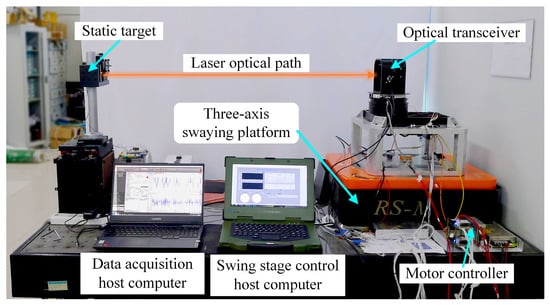
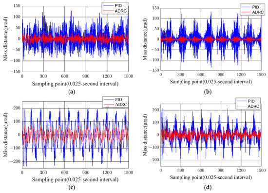
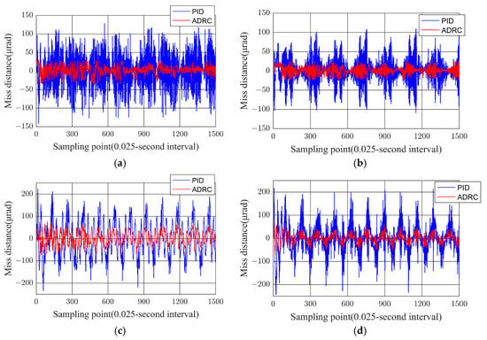
To validate the boresight stabilization accuracy and robustness of the system under realistic noise conditions, sinusoidal motion data measured by a gyroscope, which had an amplitude of 5° and frequencies of 0.3 Hz, 1.5 Hz, and 3 Hz, were used as the input signals. Through hardware-in-the-loop simulation, the error between the controller’s output response and the reference sinusoidal signal was obtained, as shown in Figure 4.
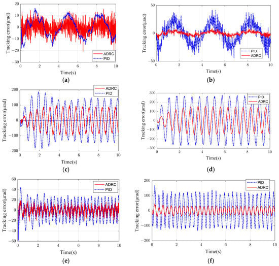
Figure 4.
Comparison of tracking error of gyroscope noise in azimuth controller: (a) Sinusoidal 0.3 Hz disturbance input for the azimuth axis; (b) Sinusoidal 0.3 Hz disturbance input for the pitch axis; (c) Sinusoidal 1.5 Hz disturbance input for the azimuth axis; (d) Sinusoidal 1.5 Hz disturbance input for the pitch axis; (e) Sinusoidal 3 Hz disturbance input for the azimuth axis; (f) Sinusoidal 3 Hz disturbance input for the pitch axis.
As shown in Figure 4, the tracking errors of both controllers exhibit a frequency-dependent growth trend as the sinusoidal disturbance frequency increases. Notably, the error amplitude under ADRC remains consistently lower than that of PID across the tested frequency range, confirming its superior disturbance rejection capability. Specifically, the ADRC error curve rises gradually with a relatively flat slope, whereas the PID error curve demonstrates a steeper ascent, indicating higher sensitivity to dynamic perturbations.
This divergence can be attributed to the inherent structural advantages of ADRC. Its ESO actively estimates and compensates for complex disturbances in real time, thereby attenuating the impact of high-frequency base vibrations.
In contrast, PID control lacks such a disturbance compensation mechanism, leading to accelerated performance degradation as the frequency escalates—a critical limitation in precision-critical applications like laser communication.
For laser communication systems requiring micro-radian-level stabilization accuracy, the frequency resilience of ADRC is indispensable. By effectively isolating platform-induced vibrations, ADRC ensures robust acquisition and maintenance of laser links, outperforming PID in scenarios involving rapid disturbance variations. The stable error characteristics of ADRC, as evidenced by its flatter frequency–response curve, underscore its suitability for high-accuracy optical pointing applications.
7. Conclusions
This study proposes a genetic algorithm-optimized distributed GA-ADRC framework for the intelligent control of complex electromechanical systems in laser communication networking. This study addresses core challenges such as strong nonlinearity, time-varying parameters, and multi-channel coupling. To this end, we introduce a co-optimized hardware-control architecture and a novel control strategy. The architecture employs a shared inertial measurement unit combined with distributed control to achieve dynamic decoupling. The strategy integrates intelligent optimization with active disturbance rejection.
The architecture employs a shared inertial measurement unit combined with distributed control to achieve dynamic decoupling. The strategy incorporates a genetic algorithm to coordinate multi-loop parameters systematically, thereby overcoming the limitations of traditional trial-and-error tuning methods.
The ADRC’s core strength lies in estimating and compensating for generalized total disturbances, including time-varying parameter variations (e.g., temperature-induced moment of inertia changes), enabling robust adaptability. In orbit and UAV applications, common drifts (temperature- or vibration-related) and their combinations result in limited accuracy degradation, with performance remaining compliant with laser communication requirements. Future work will explore online adaptive optimization via GA and deep reinforcement learning integration to further enhance adaptability.
More importantly, Hardware-in-the-Loop (HIL) tests have confirmed that the optimized GA-ADRC controller runs in real time on our STM32H743ZI-based embedded platform. The computational load of the ADRC algorithm is deterministic and manageable, demonstrating the practical feasibility of the proposed approach for applications with strict constraints on size, weight, and power, such as satellite optical terminals and UAVs.
Future investigations will advance along two interconnected trajectories to enhance both theoretical foundations and practical implementation of intelligent control systems. The primary direction involves developing online adaptive control mechanisms through deep integration of Deep Reinforcement Learning with Active Disturbance Rejection Control architecture, enabling real-time parameter self-tuning that surpasses current offline optimization limitations. This approach facilitates dynamic adjustment of control parameters based on operational feedback, ensuring robust performance under varying environmental conditions and unmodeled dynamics. Concurrently, research will focus on computational optimization through algorithm lightweighting and hardware-aware implementations for edge deployment. This direction addresses critical Size, Weight, and Power constraints by developing computationally efficient versions specifically designed for high-performance edge-computing devices, enabling practical implementation in autonomous unmanned systems and space communication platforms. These complementary research pathways will bridge theoretical advances with practical applications, paving the way for next-generation intelligent control systems capable of autonomous operation in complex, dynamic environments while meeting stringent resource constraints.
Author Contributions
Overall research design and analysis, L.Z. and L.W.; writing and programming, L.W.; review and editing, L.M.; supervision and simulation, Y.B.; data analysis and review, L.Z. All authors have read and agreed to the published version of the manuscript.
Funding
This research was funded by Inner Mongolia Natural Science Foundation of China (Grant No. 2024LHMS06026) and the Joint Funds of the National Natural Science Foundation of China (Grant No. U2141231) and Inner Mongolia Minzu University Doctoral Start-up Fund (Grant No. BSZ029).
Data Availability Statement
All data generated and analyzed during this study are included in this article.
Conflicts of Interest
The authors declare no conflicts of interest.
Abbreviations
The following abbreviations are used in this manuscript:
| LOS | line of sight |
| GA-ADRC | genetic algorithm-optimized active disturbance rejection control |
| PID | Proportional Integral Derivative |
| IMU | inertial measurement unit |
| ADRC | Active Disturbance Rejection Control |
| GA | Genetic Algorithm |
| MIMO | multi-input multi-output |
| GEO | geostationary orbit |
| LEO | low Earth orbit |
| MEMS | micro electromechanical system |
| TD | Tracking Differentiator |
| ESO | Disturbance Estimation via Extended State Observer |
| NSEF | Nonlinear State Error Feedback |
| CCD | Charge Coupled Device |
| LESO | linear extended state observer |
| LSEF | linear state error feedback |
| HIL | hardware-in-the-loop |
| PID | Proportion Integration Differentiation |
References
- Toyoshima, M. Recent trends in space laser communications for small satellites and constellations. J. Light. Technol. 2021, 39, 693–699. [Google Scholar] [CrossRef]
- Alimi, I.; Monteiro, P. Revolutionizing Free-Space Optics: A Survey of Enabling Technologies, Challenges, Trends, and Prospects of Beyond 5G Free-Space Optical (FSO) Communication Systems. Sensors 2024, 24, 8036. [Google Scholar] [CrossRef]
- Mohageg, M.; Mazzarella, L.; Anastopoulos, C.; Gallicchio, J.; Hu, B.-L.; Jennewein, T.; Johnson, S.; Lin, S.-Y.; Ling, A.; Marquardt, C.; et al. The deep space quantum link: Prospective fundamental physics experiments using long-baseline quantum optics. EPJ Quantum Technol. 2022, 9, 25. [Google Scholar] [CrossRef]
- Ullah, R.; Ullah, S.; Ren, J.; Alwageed, H.S.; Mao, Y.; Qi, Z.; Wang, F.; Khan, S.A.; Farooq, U. Beyond Fiber: Toward Terahertz Bandwidth in Free-Space Optical Communication. Sensors 2025, 25, 2109. [Google Scholar] [CrossRef] [PubMed]
- Phuchortham, S.; Sabit, H. A Survey on Free-Space Optical Communication with RF Backup: Models, Simulations, Experience, Machine Learning, Challenges and Future Directions. Sensors 2025, 25, 3310. [Google Scholar] [CrossRef]
- Ding, C.; Li, C.; Wang, Z.; Gao, Z.; Liu, Z.; Song, J.; Tao, M. Free Space Optical Communication Networking Technology Based on a Laser Relay Station. Appl. Sci. 2023, 13, 2567. [Google Scholar] [CrossRef]
- Hamilton, A. Strapdown optical stabilization system for EO sensors on moving platforms. In Proceedings of the Design and Engineering of Optical Systems, Glasgow, UK, 13–16 May 1996; pp. 631–645. [Google Scholar] [CrossRef]
- Li, J.; Li, J.; Qin, L.; Liu, W.; Wei, X.; Gao, N.; Liu, Y. Optimal Design and Analysis on High Overload Buffer Structure of Passive Semi-Strapdown Inertial Navigation System. Sensors 2020, 20, 1131. [Google Scholar] [CrossRef]
- Wei, X.; Li, J.; Zhang, D.; Feng, K.; Zhang, J.; Li, J.; Lu, Z. Optimization of a New High Rotary Missile-Borne Stabilization Platform. Sensors 2019, 19, 4143. [Google Scholar] [CrossRef] [PubMed]
- Boroson, D.; Robinson, B. The lunar laser communication demonstration: NASA’s first step toward very high data rate support of science and exploration missions. Space Sci. Rev. 2014, 185, 115–128. [Google Scholar] [CrossRef]
- Chaudhry, A.; Yanikomeroglu, H. Free Space Optics for Next-Generation Satellite Networks. IEEE Consum. Electron. Mag. 2021, 10, 21–31. [Google Scholar] [CrossRef]
- Wang, L.; Zhang, L.; Meng, L.; Bai, Y. A study of modeling method of strapdown stable attitude in laser communication networking. Opt. Rev. 2023, 30, 190–198. [Google Scholar] [CrossRef]
- Wang, J.; Song, Y.; Jiang, H.; Wang, T.; Ren, B. Research and Dynamic Demonstration Test of One-Point to Multi-Point Space Laser Communication System. In Proceedings of the 2021 13th International Conference on Advanced Infocomm Technology (ICAIT), Yanji, China, 15–18 October 2021; pp. 143–146. [Google Scholar] [CrossRef]
- Wang, L.; Zhang, L.; Meng, L.; Bai, Y. Numerical Calculation for the Line-of-Sight Attitudes of Multi-Address Transceivers without 2:1 Transmissions for Space Laser Communication Networking. Electronics 2023, 12, 1575. [Google Scholar] [CrossRef]
- Wang, L.; Zhang, L.; Meng, L.; Bai, Y. A calculation method for line-of-sight stable attitude of networked optical transceiver based on depth feedforward neural network. In Proceedings of the 2022 3rd International Conference on Computer Vision, Image and Deep Learning & International Conference on Computer Engineering and Applications (CVIDL & ICCEA), Changchun, China, 20–22 May 2022; pp. 32–35. [Google Scholar] [CrossRef]
- Sang, N.; Chen, L. Design of an active front steering system for a vehicle using an active disturbance rejection control method. Sci. Prog. 2020, 103, 36850419883565. [Google Scholar] [CrossRef]
- Abadi, A.; Ayeb, A.; Labbadi, M.; Fofi, D.; Bakir, T.; Mekki, H. Robust Tracking Control of Wheeled Mobile Robot Based on Differential Flatness and Sliding Active Disturbance Rejection Control: Simulations and Experiments. Sensors 2024, 24, 2849. [Google Scholar] [CrossRef]
- Khadraoui, S.; Fareh, R.; Baziyad, M.; Elbeltagy, M.B.; Bettayeb, M. A Comprehensive Review and Applications of Active Disturbance Rejection Control for Unmanned Aerial Vehicles. IEEE Access 2024, 12, 185851–185868. [Google Scholar] [CrossRef]
- Tu, Y.; Wang, R.; Su, W. Active disturbance rejection control—New trends in agricultural cybernetics in the future: A comprehensive review. Machines 2025, 13, 111. [Google Scholar] [CrossRef]
- Han, J. From PID to active disturbance rejection control. IEEE Trans. Ind. Electron. 2009, 56, 900–906. [Google Scholar] [CrossRef]
- Zhao, S.; Gao, Z. Modified active disturbance rejection control for time-delay systems. ISA Trans. 2014, 53, 882–888. [Google Scholar] [CrossRef]
- Sui, X.; Yang, Y. Quasi-Mittag-Leffler Projective Synchronization of Delayed Chaotic Fractional Order Neural Network with Mismatched Parameters. Fractal Fract. 2025, 9, 379. [Google Scholar] [CrossRef]
- Elghardouf, N.; Ennaciri, Y.; Elakkary, A.; Sefiani, N. Multi-loop active disturbance rejection control and PID control strategy for poultry house based on GA, PSO and GWO algorithms. Heliyon 2024, 10, e29579. [Google Scholar] [CrossRef] [PubMed]
- Ge, J.; Guo, X.; Liu, Y. Attitude Control of Quad-Rotor UAV Based on GA-ADRC. Dyn. Syst. Control 2020, 9, 109–120. [Google Scholar] [CrossRef]
- Zhou, X.; Gao, H.; Zhao, B.; Zhao, L. A GA-based parameters tuning method for an ADRC controller of ISP for aerial remote sensing applications. ISA Trans. 2018, 81, 318–328. [Google Scholar] [CrossRef] [PubMed]
- Majhi, N.; Mishra, R. A novel hybrid genetic algorithm and Nelder-Mead approach and it’s application for parameter estimation. F1000Research 2025, 13, 1073. [Google Scholar] [CrossRef]
- Vu, M.T.; Kim, S.H.; Pham, D.H.; Thanh, H.L.N.N.; Pham, V.H.; Roohi, M. Adaptive Dynamic Programming-Based Intelligent Finite-Time Flexible SMC for Stabilizing Fractional-Order Four-Wing Chaotic Systems. Mathematics 2025, 13, 2078. [Google Scholar] [CrossRef]
Disclaimer/Publisher’s Note: The statements, opinions and data contained in all publications are solely those of the individual author(s) and contributor(s) and not of MDPI and/or the editor(s). MDPI and/or the editor(s) disclaim responsibility for any injury to people or property resulting from any ideas, methods, instructions or products referred to in the content. |
© 2025 by the authors. Licensee MDPI, Basel, Switzerland. This article is an open access article distributed under the terms and conditions of the Creative Commons Attribution (CC BY) license (https://creativecommons.org/licenses/by/4.0/).
