Abstract
This paper presents a composite control strategy for gearless coal mill to improve the disturbance immunity under low-speed variable operating conditions. First, the gearless coal mill encounters power supply voltage fluctuations, mechanical failures, or ambient temperature changes during operation. These situations can cause the system to suffer from the problem of insufficient control accuracy of the rotational speed. Therefore, a non-singular fast terminal sliding mode control strategy is proposed to improve the speed response. Then, to address the problem of load perturbation caused by different coal quality, this paper designs the extended state observer. Feed-forward compensation of the perturbation is performed to improve the robustness. Finally, due to the parameter mismatch problem caused by heat in operations that take a long time, this paper proposes a sliding-mode-based deadbeat predictive current control. The strategy possesses the fast dynamic response of deadbeat predictive current control while retaining the strong robustness of sliding mode control. Lyapunov proved the stability of the proposed control strategy. The experimental results verified that the proposed control strategy had better control performance.
1. Introduction
As a modern grinding machine, the gearless coal mill plays a crucial role in thermal power generation and other heavy industries. Its efficient operation relies on the powerful performance of its internal drive motor [1]. Therefore, the stability of the drive motors inside gearless coal mill needs to be improved. Nowadays, permanent magnet synchronous motor (PMSM) has been widely adopted in coal mills due to its simple structure, high efficiency, and high power factor [2,3]. However, the different coal qualities can cause the motor to operate under variable load conditions, which leads to excessive speed overshoot and poor dynamic performance. In addition, the mismatch of motor model parameters also occurs because the coal mill often operates at high temperatures, which affects the robustness of the system current [4]. Therefore, it is of great theoretical significance and application value to research control methods with strong robustness and high dynamic performance for the gearless coal mill system under variable load perturbation and model parameter mismatch. For example, the driving device of mining scraper conveyor used in a coal mining face is a typical low-speed and high-torque motor drive system, it is shown in Figure 1.
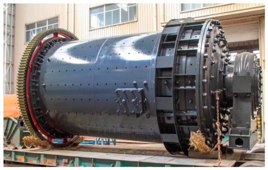
Figure 1.
Gearless coal mill.
In order to overcome the problems arising from the use of traditional PI control strategies for gearless coal mill, such as large overshoot, poor robustness in the face of disturbances, and so on, many researchers have proposed a variety of nonlinear control schemes. These include adaptive control, fuzzy control, neural network control, sliding mode control (SMC), etc. Adaptive control can encounter changes in system parameters or the presence of external perturbations, which can maintain the system from significant effects through online learning and self-adjustment mechanisms. The disadvantage is that changing the control performance indicators based on the information received makes running slower. The time required for online identification and correction is long, meaning that fast motor control cannot be achieved [5,6]. Fuzzy control can efficiently deal with uncertainty and nonlinear problems. Intelligent and flexible control of complex systems is achieved by imitating natural human thinking. However, due to the fuzzy processing of the information, the control accuracy decreases. Meanwhile, this control makes it difficult to eliminate the steady-state error, so it is not possible to achieve accurate control of the motor [7,8]. Neural network control can self-learn, optimize, and quickly find the optimal solution. The disadvantage is that its calculation process is too complicated. Most of the current research results are only given in the form of a simulation. In practical engineering applications, the control algorithms do not give good results compared to others [9,10]. SMC has the advantages of fast response, insensitivity to parameter changes and disturbances, and simple physical implementation. It is more suitable for industrial use than other control strategies [11]. However, the traditional SMC has a fundamental limitation: the convergence speed and stability cannot be balanced [12,13]. Therefore, many scholars have proposed to solve this problem by ameliorating the reaching law. In [14], a terminal sliding mode is applied to give better zero convergence of the state variables, and there is robust to model errors as well as external disturbances. In [15], a sliding mode surface consisting of differential and integral fractional order is designed. The speed tracking accuracy and interference suppression of the conventional SMC are enhanced. In [16], in order to enhance the reaching speed and chattering suppression ability, this paper proposes an SMC method based on a novel sliding mode reaching law (NSMRL). In [17], a nonlinear integral sliding mode surface is designed by introducing sign and fractional error integration. This achieves finite time convergence of the velocity tracking error and the integration error.
In complex industrial environments, gearless coal mills face diverse and unpredictable disturbance sources. If only relying on traditional control algorithms, it is difficult to meet the requirements of high accuracy and robustness. It is necessary to add feed-forward compensation to the controller to improve the anti-disturbance performance. It is worth noting that the quality of the feed-forward compensation is directly affected by the observer. Therefore, the theory of the disturbance observer has received increased attention in recent years. In [18], a simple adaptive current perturbation observer is proposed to estimate the time-varying and high-bandwidth characteristics. In [19], in order to further improve the SMC immunity, a second-order non-singular terminal sliding mode observer is designed to estimate the load perturbation and suppress the chattering. In [20], a super-twisted sliding mode speed controller with a disturbance observer is proposed for the PMSM time-varying disturbance problem. Although all of these methods are beneficial for enhancing the robustness and anti-disturbance ability, there are still some problems, such as a too-complex mathematical model, difficult parameter adjustment, and singularities during the simulation process.
On the other hand, the advancement of FOC has led to a significant focus on deadbeat predictive current control (DPCC) in recent years due to its simple control process, ease of implementation, and exceptional dynamic performance [21]. However, the DPCC methodology also needs to propose solutions to the problem of model parameter mismatch or parameter uncertainty. One of the methods is to utilize disturbance observation or error compensation measures, such as the observer [22], integral compensation, and feed-forward compensation [23]. In [24], a disturbance observer with a novel sliding mode reaching law is proposed based on DPCC. The controller can simultaneously estimate the perturbations due to current and parameter mismatch. In [25], a composite sliding mode disturbance observer (SMDO) is proposed to improve the deadbeat prediction controller. This method can estimate the disturbances in the case of mismatched motor parameters. In [26], a novel Luenberger observer is designed to estimate disturbances and mismatches in the d-q axis current loop. Furthermore, another approach is to enhance the precision of the motor model parameters, such as the introduction of parameter identification methods. In [27], a novel PI combined DPCC controller with weights determined online by a fuzzy algorithm is employed. However, this method also affects the dynamic performance of the DPCC. In [28], to address the impact of motor parameter mismatch on the system, a new online accuracy verification method of the parameter identification results is proposed to determine the error estimation level. Ref. [27] proposed robust model predictive control (MPC) for permanent magnet synchronous motors by taking into account the effect of disturbance. A structure cascading extended Kalman filter (EKF) and linear extended state observer (LESO) are used to estimate the position of the motor without using encoders. Therefore, it is essential to design a relatively simple control method to achieve the improvement in DPCC parameter robustness.
To address the above issues, this paper proposes a composite controller including a non-singular fast terminal sliding mode speed controller (NFTSMC), an extended state observer (ESO), and a sliding-mode-based deadbeat predictive current controller. The controller mainly improves the stability, robustness, and rapidity of the gearless coal mill. The main contributions are clarified as follows. (1) The gearless coal mill model considering parameter uncertainty and external disturbances is established. (2) The NFTSM speed controller is proposed to improve the accuracy of the gearless coal mill system in controlling the rotational speed. ESO enhances the rotational speed robustness through estimating unknown perturbations and feed-forward compensation. (3) The sliding-mode-based deadbeat predictive current controller is proposed to overcome the model parameter mismatch. The method effectively improves the robustness of the current loop, and the system maintains good dynamic performance as well as steady-state performance.
2. Mathematical Model of PMSM
The PMSM system for gearless coal mill drives has many complex characteristics, such as high order, nonlinearity, multivariate coupling, and large rotational inertia. These characteristics greatly increase the difficulty of modeling the gearless coal mill. First, the working process of the coal mill involves multiple physical and chemical changes, such as coal crushing, grinding, drying, etc. These complex nonlinear relationships make it difficult to describe the dynamic model of the coal mill accurately. Secondly, the coal mill system requires a larger moment of inertia than other motor systems, which can exacerbate the coupling relationship between multiple variables such as rotational speed, load, power consumption, etc. This makes it more difficult to accurately express the relationship between these variables when establishing a mathematical model. Meanwhile, a larger moment of inertia also increases the model’s sensitivity to other parameters. Finally, factors such as the operating conditions of the coal mill and coal quality may change over time. For example, parameters such as coal hardness and humidity may vary with mining locations and seasons. These variations can affect the operating performance of the coal mill, meaning that the accuracy of the model suffers [29,30].
For analysis, some basic assumptions are made before the mathematical model is developed: (1) The motor stator current is a symmetrical three-phase sinusoidal current. (2) Neglecting the higher harmonics, the windings are symmetrically distributed in three phases. (3) Core saturation, eddy current, and hysteresis losses are excluded in the motor. (4) The effect of frequency change and temperature increase on parameters such as winding resistance is not taken into account.
The stator windings of a three-phase PMSM are spatially symmetrical to each other. The voltage equation for a three-phase surface-mounted PMSM in the d-q coordinate system is established as follows:
where and are the d-q axis components of the stator voltage; and are the d-q axis components of the stator current; R is the resistance of the stator; is the permanent magnet magnetic chain; and are the d-q axis inductance components; and is the electrical angular speed.
The electromagnetic torque equation for PMSM is as follows:
where is the number of magnetic pole pairs. For the surface-mounted PMSM , the electromagnetic torque equation can be transformed into the following:
The mechanical equation of motion for PMSM is as follows:
where is the mechanical angular velocity; J is the moment of inertia; B is the damping factor; is the electromagnetic torque; and is the load torque.
If the vector control in control scheme, by substituting (3) into (4), we obtain the following:
3. Design of Speed Loop
3.1. Non-Singular Terminal Sliding Mode Controller
The sliding mode motion is unaffected by changes in system parameters and external disturbances. Therefore, the SMC can increase the system robustness compared with the general controller. However, the complex and variable working conditions of gearless coal mill should be considered. If only applying the traditional sliding mode surface to the control system, the system suffers from large speed overshoot and slow speed tracking. Therefore, the non-singular sliding mode surface is used to replace the traditional one. Non-singular sliding mode surfaces can be constructed to avoid singularities, ensuring that the control signal is finite and continuous in all states. Using this method can alleviate the inherent chattering problem when the system enters the sliding mode stage. This can also accelerate the response speed and enhance the robustness and stability.
The state variables of the PMSM system are defined as follows:
where is the reference mechanical angular velocity; ωm is the actual mechanical angular velocity.
The rate of change in error is as follows:
According to (7), the following expression can be obtained:
To obtain a better performance, an NTFSMC surface is chosen. The sliding mode surface function is defined as follows:
where x1, x2 are system state variables; ; ; m, n are positive odd numbers; and . x1, x2 have no negative exponential terms. Therefore, the sliding mode surface-based velocity controller avoids the singularity problem.
When , the rate of change in the velocity error is as follows:
According to the above equation, when the system error moves to the sliding mode surface, the convergence rate is mainly affected by the exponential term . When the state variable is close to the sliding mode surface, the convergence speed is mainly affected by the linear term x1. The combination of the two ensures that the error converges quickly at different convergence stages.
Derivation of (9) yields the following:
Then, substituting (8) into (11) yields the following:
Let , iq=u; taking a conventional exponential reaching law, the expression for the reference current in the q-axis is given by the following (12):
where μ is the SMC switching gain.
To verify the stability of the designed controller, the Lyapunov function is selected ; then,
From (14), the designed control system is stable.
3.2. Extended State Observer
The inherent chattering vibration in the slip mode control system was improved by designing a non-singular sliding mode surface. However, gearless coal mill is subject to uncertain load disturbances due to fluctuations in coal quality and other factors. Only adjusting the controller amplitude to suppress the load perturbation will reduce the speed robustness. In order to reduce the impact of load disturbances on the system, the ESO is used to observe the load disturbances in real time. The observed values are fed back to the speed controller. This process reduces the speed and torque chattering.
First, rewrite (5) as follows:
where ; are the integrated perturbations, and the second-order nonlinear ESO is designed as follows:
where fal () is a classical nonlinear function expressed as follows:
where z1 denotes velocity estimation; z2 denotes perturbation estimation; e1=z1-ωe; x is the filtering factor; and λ0, λ1 are the ESO filtering coefficients. The observed load torque values are added to the speed controller to improve the resistance to load disturbances.
4. Design of Current Loop
Considering that gearless coal mills are often subject to high temperatures, the conventional PI-controlled current loop is unable to meet the stable operation of the system. To address the above issues, a deadbeat predictive current controller is designed in the current loop. Since, in the traditional DPCC method, the reference voltage is directly derived from the voltage in Equation (1), the system performance will change when there are model parameter mismatches.
When parameter mismatch is considered, the voltage equation of the PMSM can be rewritten as follows:
where fd and fq denote the perturbations caused by the mismatch of motor parameters, which can be characterized as follows:
where ∆R, ∆L, and ∆φf are the changes in resistance, inductance, and magnetic chain.
From (18) and (19), the reference voltage is obtained directly from the voltage equation. This leads to voltage errors in the d-q axis. Therefore, a sliding mode-based deadbeat predictive current controller is proposed, which can effectively suppress the negative impact of parameter mismatch. Simultaneously, the current prediction is used to compensate for the one-step delay caused by digital control. The formula is as follows:
where id (k+1) and iq (k+1) denote the one-step delay compensation currents in the d-q axis. Id (k) and iq (k) denote the measured currents. ud (k) and uq (k) denote the measured voltages.
Then, based on the voltage (1) and the principle of DPCC, the voltage reference can be predicted to be the following:
First, the current error is selected as the surface of the sliding mode, which has the following expression:
where and denote the reference currents on the d-q axis.
The proposed sliding mode current control function consists of two components, and usmc; they satisfy the following expressions:
In (23), the is identical to the conventional expression (25) for deadbeat predictive current control. usmcdq is designed as follows:
Then, by substituting the exponential convergence law into (24), we obtain the following:
The d-q axis voltage obtained from (23) is converted to α-β axis voltage by coordinate transformation. It is used as the input of space vector pulse width modulation (SVPWM).
Stability analysis: To ensure the stability of the proposed controller under parameter mismatch conditions, the following conditions and must be satisfied.
On the d-axis, according to (22), the can be expressed as follows:
Next, because of (26), it is possible to obtain the following:
Then, by substituting the proposed control function (23) into (27), we obtain the following:
Thus, the d-axis stability condition can be represented as follows:
Under the condition of satisfying Equation (30), when , it is necessary to satisfy the following expression:
where . On the other hand, in the case of , the following expression needs to be satisfied:
By combining (30) and (31), the following conclusions can be drawn:
When there is parameter mismatch, the d-axis controller parameters ε and k should comply with the requirements of relation (32) to ensure controller stability.
In the same way, in the q-axis, relation (33) also needs to be fulfilled to keep the stability of the q-axis controller.
Among other things, .
Therefore, with the proposed sliding mode current control function , the control performance deterioration caused by model parameter mismatch can be effectively suppressed. The input of this controller is the d-q axis current error value. The output is the predicted voltage value, which is used as the input of SVPWM.
5. Experimental Verification
To verify the effectiveness of the proposed control strategy, experimental validation is carried out on the PMSM platform, as shown in Figure 2. The experimental measurements are exported and displayed in MATLAB. The parameters of the PMSM experimental platform are shown in Table 1. In this section, three comparison experiments are conducted (in which the proposed method involves the dual closed-loop PI control and SMC-DPCC methods). The block diagram of the vector control principle of the PMSM is shown in Figure 3. The speed control is used as the outer loop, and the current control is used as the inner loop. The ESO observes the load changes and compensates them to the speed controller. The parameters of the NFTSM controller are α = 5000; β = 5000; p = 65; q = 61; m = 15; n = 11; η = 10; μ = 8. The parameters of sliding-model-based deadbeat predictive current control are ε = 2; k = 400, the motor’s rated speed is 300 rpm, and the rated load is 50 N.m.
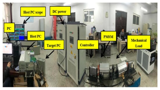
Figure 2.
Experimental platform based on Xpc-Target.

Table 1.
PMSM parameters.
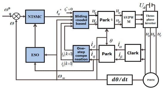
Figure 3.
Block diagram of the proposed control strategy.
5.1. Performance Analysis of External Disturbance Under Step Condition
In Figure 4, PMSM is started at 50 rpm under no load conditions. The speed is increased to 100 rpm at 0.3 s and 150 rpm at 0.6 s. Figure 4 shows that the overshoots of the dual PI, SMC-DPCC, and the proposed method are 55 rpm, 65 rpm, and 0 rpm. The arrival times are 0.2 s, 0.25 s, and 0.075 s. Due to the design of non-singular sliding mode surfaces in the method proposed in this paper, the rotor speed quickly tracks the reference speed without overshoot. When the rotor speed is 100 rpm, the steady-state errors are 7 rpm, 4.5 rpm, and 0.0008 rpm. Since the PI control is affected by perturbations, the integral action is not effective in reducing the steady-state error. The speed curve under SMC is smoother and the stability is improved, but the speed overshoot increases, and the speed cannot reach the given speed quickly. Since the speed pulsation is minimized under the control proposed in this paper, the method has a good control effect. In addition, the system can realize no overshoot and a fast response.
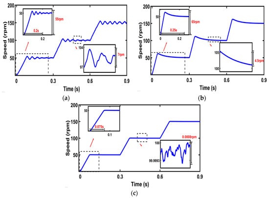
Figure 4.
Speed diagrams for the three control strategies. (a) Rotational speed of dual PI; (b) rotational speed of SMC-DPCC; (c) rotational speed of the proposed method.
5.2. Performance Analysis of Change Disturbance Under Step Condition
Figure 5 shows that the PMSM starts at 100 rpm under the load perturbation every 0.3 s to simulate the motor variable load operation. The rotor speed and q-axis current under different control strategies are as follows: In Figure 5a–c, when the load torque suddenly changes from 0 N*m to 50 N*m in 0.3 s, the reduction speeds of PI, SMC-DPCC, and the proposed method are 2.5 rpm, 18 rpm, and 0.7 rpm, respectively. For the dual PI and the method proposed in this paper, the times to go back to 100 rpm are 0.1 s and 0.23 s, respectively, and the SMC-DPCC cannot return to the given speed quickly. When the system is under load torque of 50 N*m, the steady-state errors of dual PI, SMC-DPCC, and the proposed method are 2.3 rpm, 0.3 rpm, and 0.004 rpm. It can be seen that the system under dual PI control has a large fluctuation in system speed when it is frequently subjected to disturbances. The system under SMC-DPCC experiences a large speed change when it is subjected to disturbances, but it can keep the operation in a smooth state. When the system under the control of the method in this paper is subjected to disturbances, the disturbance observer can reduce the impact of disturbances, quickly compensate, and improve the robustness.
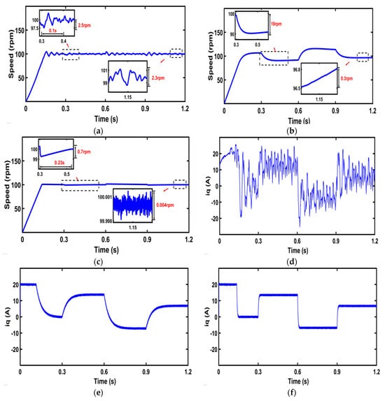
Figure 5.
Comparative analysis of rotational speed and q-axis current curve under different control strategies under variable load. (a) Rotational speed of dual PI; (b) rotational speed of SMC-DPCC; (c) rotational speed of the proposed method; (d) q-axis current of dual PI; (e) q-axis current of SMC-DPCC; (f) q-axis current of the proposed method.
In Figure 5d–f, the comparative analysis of the q-axis current under different control strategies during mismatch perturbation is shown. When the system is subjected to a load disturbance, the dual PI control strategy produces huge fluctuations in the q-axis current. Since the q-axis currents under the control of the proposed method remain smooth and their fluctuations are minimized, this can suppress the effects of load fluctuations.
When the PMSM is started at 100 rpm under the load torque of 50 N*m., the d-axis current and q-axis current of the PMSM under different control strategies are shown in Figure 6. In Figure 6a–c, the steady-state errors of the d-axis current are 6.5 A, 1.65 A, and 1.6 A for the dual PI, SMC-DPCC, and the proposed method. The steady-state errors of the q-axis current are 8 A, 1.6 A, and 1.5 A. From the figure, it can be seen that the d-axis currents and q-axis currents under the dual PI control strategy have larger steady-state errors. The q-axis currents under the SMC-DPCC strategy take a longer amount of time to reach steady-state.
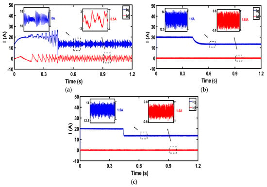
Figure 6.
Comparative analysis of d-axis current curves and q-axis current curves with low-speed and high-torque. (a) d-q axis current of dual PI; (b) d-q axis current of SMC-DPCC; (c) d-q axis current of the proposed method.
5.3. Performance Analysis of Internal Parameter Perturbation Under Step Condition
In Figure 7a–c, when the resistance in the model is twice the actual resistance, the steady-state errors of the d-axis current are 6.5 A, 1.7 A, and 1.6 A for the dual PI, SMC-DPCC, and the proposed method. Those of the q-axis current are 7.5 A, 1.6 A, and 1.5 A, respectively. The current value of the d-axis current steady-state error has changed under the dual PI control strategy. The current value of the d-axis current steady-state error has changed under the SMC-DPCC strategy. However, there is no significant change in the currents when using the method outlined in this paper.
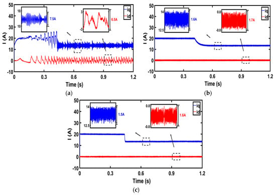
Figure 7.
Comparative analysis of d-axis current curves and q-axis current curves with different resistance parameters. (a) d-q axis current of dual PI; (b) d-q axis current of SMC-DPCC; (c) d-q axis current of the proposed method.
In Figure 8a–c, when the inductance in the model is twice the actual inductance, for the dual PI, SMC-DPCC, and the proposed methods, the steady-state errors of the d-axis current are 3.5A, 0.8A, and 0.8A, respectively, and those of the q-axis current are also 3.5A, 0.8A, and 0.8A, respectively. All three control strategies had a variation in the current values. The maximum value of the variation was in the steady-state error in the d-axis current and q-axis under the dual PI control strategy, whereas the motor under the method of this paper has the minimum variation in the d-axis current and q-axis current.
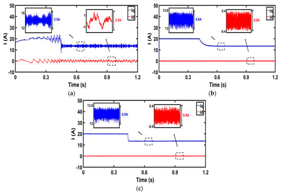
Figure 8.
Comparative analysis of d-axis current curves and q-axis current curves with different inductance parameters. (a) d-q axis current of dual PI; (b) d-q axis current of SMC-DPCC; (c) d-q axis current of the proposed method.
6. Conclusions
In this paper, the system is designed to address the problems encountered in the working condition of gearless coal mill. Firstly, uncertain perturbations can occur in the motor due to the quality of the coal. The system can suffer from poor performance due to prolonged operation under variable load conditions. To solve these issues, an NFTSMC strategy is adopted in the speed loop to reduce the convergence time of the rotational speed. Meanwhile, the load change value of the system is observed and compensated in real time by introducing an ESO. This well solves the problem of large speed fluctuations and poor robustness of the system during operation. Secondly, in the gearless coal mill, the mismatch of model parameters due to heat or vibration deteriorates the system performance. To address this, a sliding-model-based deadbeat current controller is used in the current loop. Finally, the proposed method is experimentally verified with the dual PI control strategy and the SMC-DPCC strategy. The experimental results show the effectiveness of the control strategy.
Author Contributions
Conceptualization and methodology, Q.W.; software, M.Z.; validation, Q.W. and M.Z.; resources, M.Z.; writing—original draft preparation, Q.W. and M.Z.; writing—review and editing, Q.W. and C.J. All authors have read and agreed to the published version of the manuscript.
Funding
This research was funded by Jilin Provincial Scientific and Technological Development Program under Grant 20230201116GX.
Institutional Review Board Statement
Not applicable.
Informed Consent Statement
Not applicable.
Data Availability Statement
The original contributions presented in this study are included in the article. Further inquiries can be directed to the corresponding author(s).
Conflicts of Interest
Author Mingduo Zhang was employed by Datang Jilin Power Generation Co., Ltd. The remaining authors declare that the research was conducted in the absence of any commercial or financial relationships that could be construed as a potential conflict of interest.
References
- Agrawal, V.; Panigrahi, B.K.; Subbarao, P.M.V. Intelligent decision support system for detection and root cause analysis of faults in coal mills. IEEE Trans. FuzzySyst. 2016, 25, 934–944. [Google Scholar] [CrossRef]
- Wang, G.; Valla, M.; Solsona, J. Position sensorless permanent magnet synchronous machine drives—A review. IEEE Trans. Ind. Electron. 2019, 67, 5830–5842. [Google Scholar] [CrossRef]
- Zhang, X.; Wang, Z. Simple robust model predictive current control for PMSM drives without flux-linkage parameter. IEEE Trans. Ind. Electron. 2022, 70, 3515–3524. [Google Scholar] [CrossRef]
- Xu, P.L.; Zhu, Z.Q. Novel carrier signal injection method using zero-sequence voltage for sensorless control of PMSM drives. IEEE Trans. Ind. Electron. 2015, 63, 2053–2061. [Google Scholar] [CrossRef]
- Nguyen, A.T.; Rafaq, M.S.; Choi, H.H.; Jung, J.W. A model reference adaptive control based speed controller for a surface-mounted permanent magnet synchronous motor drive. IEEE Trans. Ind. Electron. 2018, 65, 9399–9409. [Google Scholar] [CrossRef]
- Reed, D.M.; Sun, J.; Hofmann, H.F. Simultaneous identification and adaptive torque control of permanent magnet synchronous machines. IEEE Trans. Control. Syst. Technol. 2016, 25, 1372–1383. [Google Scholar] [CrossRef]
- Vadivel, R.; Joo, Y.H. Reliable fuzzy H∞ control for permanent magnet synchronous motor against stochastic actuator faults. IEEE Trans. Syst. Man Cybern. Syst. 2019, 51, 2232–2245. [Google Scholar] [CrossRef]
- Yu, R.; Chen, Y.H.; Ding, S.; Yu, T.; Huang, J. Robust control design for fuzzy mechanical systems: A two-player Nash game approach. IEEE Trans. Syst. Man Cybern. Syst. 2022, 52, 6569–6581. [Google Scholar] [CrossRef]
- Skowron, M.; Orlowska-Kowalska, T.; Kowalski, C.T. Detection of permanent magnet damage of PMSM drive based on direct analysis of the stator phase currents using convolutional neural network. IEEE Trans. Ind. Electron. 2022, 69, 13665–13675. [Google Scholar] [CrossRef]
- Sun, X.; Chen, L.; Jiang, H.; Yang, Z.; Chen, J.; Zhang, W. High-performance control for a bearingless permanent-magnet synchronous motor using neural network inverse scheme plus internal model controllers. IEEE Trans. Ind. Electron. 2016, 63, 3479–3488. [Google Scholar] [CrossRef]
- Yin, Z.; Gong, L.; Du, C.; Liu, J.; Zhong, Y. Integrated position and speed loops under sliding-mode control optimized by differential evolution algorithm for PMSM drives. IEEE Trans. Power Electron. 2019, 34, 8994–9005. [Google Scholar] [CrossRef]
- Young, K.D.; Utkin, V.I.; Ozguner, U. A control engineer’s guide to sliding mode control. IEEE Trans. Control. Syst. Technol. 1999, 7, 328–342. [Google Scholar] [CrossRef]
- Sun, C.; Dong, X.; Wang, M.; Li, J. Sliding mode control of electro-hydraulic position servo system based on adaptive reaching law. Appl. Sci. 2022, 12, 6897. [Google Scholar] [CrossRef]
- Haghighatnia, S. A novel conformable fractional-order Terminal Sliding Mode Controller for a class of uncertain nonlinear systems. IETE J. Res. 2023, 69, 438–446. [Google Scholar] [CrossRef]
- Zaihidee, F.M.; Mekhilef, S.; Mubin, M. Application of fractional order sliding mode control for speed control of permanent magnet synchronous motor. IEEE Access 2019, 7, 101765–101774. [Google Scholar] [CrossRef]
- Wang, Y.; Feng, Y.; Zhang, X.; Liang, J. A new reaching law for antidisturbance sliding-mode control of PMSM speed regulation system. IEEE Trans. Power Electron. 2019, 35, 4117–4126. [Google Scholar] [CrossRef]
- Li, T.; Zhao, Y.; Hou, L. Adaptive sliding mode control with disturbance observer for speed regulation system of permanent magnet synchronous motor. IEEE Access 2023, 11, 17021–17030. [Google Scholar] [CrossRef]
- Mohamed, Y.A.R.I. Design and implementation of a robust current-control scheme for a PMSM vector drive with a simple adaptive disturbance observer. IEEE Trans. Ind. Electron. 2007, 54, 1981–1988. [Google Scholar] [CrossRef]
- Lu, E.; Li, W.; Yang, X.; Liu, Y. Anti-disturbance speed control of low-speed high-torque PMSM based on second-order non-singular terminal sliding mode load observer. ISA Trans. 2019, 88, 142–152. [Google Scholar] [CrossRef]
- Wang, W.; Lin, H.; Yang, H.; Liu, W.; Lyu, S. Second-order sliding mode-based direct torque control of variable-flux memory machine. IEEE Access 2020, 8, 34981–34992. [Google Scholar] [CrossRef]
- Liu, J.; Li, H.; Deng, Y. Torque ripple minimization of PMSM based on robust ILC via adaptive sliding mode control. IEEE Trans. Power Electron. 2017, 33, 3655–3671. [Google Scholar] [CrossRef]
- Ke, D.; Wang, F.; Yu, X.; Davari, S.A.; Kennel, R. Predictive error model-based enhanced observer for PMSM deadbeat control systems. IEEE Trans. Ind. Electron. 2023, 71, 2242–2252. [Google Scholar] [CrossRef]
- Song, Y.; Liu, Z.; Li, Y.C.; Li, K.J.; Guo, Z.; Huang, Z. A Fast-Response PV Simulator Based on Improved Deadbeat Predictive Current Control. IEEE J. Emerg. Sel. Top. Power Electron. 2024, 12, 2152–2162. [Google Scholar] [CrossRef]
- Zhang, X.; Hou, B.; Mei, Y. Deadbeat predictive current control of permanent-magnet synchronous motors with stator current and disturbance observer. IEEE Trans. Power Electron. 2016, 32, 3818–3834. [Google Scholar] [CrossRef]
- Sun, X.; Cao, J.; Lei, G.; Guo, Y.; Zhu, J. A robust deadbeat predictive controller with delay compensation based on composite sliding-mode observer for PMSMs. IEEE Trans. Power Electron. 2021, 36, 10742–10752. [Google Scholar] [CrossRef]
- He, L.; Wang, F.; Wang, J.; Rodríguez, J. Zynq implemented Luenberger disturbance observer based predictive control scheme for PMSM drives. IEEE Trans. Power Electron. 2019, 35, 1770–1778. [Google Scholar] [CrossRef]
- Wang, Z.; Yu, A.; Li, X.; Zhang, G.; Xia, C. A novel current predictive control based on fuzzy algorithm for PMSM. IEEE J. Emerg. Sel. Top. Power Electron. 2019, 7, 990–1001. [Google Scholar] [CrossRef]
- Wang, Y.; Liao, W.; Huang, S.; Zhang, J.; Yang, M.; Li, C.; Huang, S. A robust DPCC for IPMSM based on a full parameter identification method. IEEE Trans. Ind. Electron. 2022, 70, 7695–7705. [Google Scholar] [CrossRef]
- Xu, R.; Shen, X.; Lin, X.; Liu, Z.; Xu, D.; Liu, J. Robust Model Predictive Control of Position Sensorless Driven IPMSM Based on Cascaded EKF-LESO. IEEE Trans. Transp. Electrif. 2025, 11, 8824–8832. [Google Scholar] [CrossRef]
- Mercorelli, P. A Discrete-Time Fractional Order PI Controller for a Three Phase Synchronous Motor Using an Optimal Loop Shaping Approach. In Proceedings of the Theory and Applications of Non-integer Order Systems: 8th Conference on Non-integer Order Calculus and Its Applications, Zakopane, Poland, 28 August 2016; pp. 477–487. [Google Scholar]
Disclaimer/Publisher’s Note: The statements, opinions and data contained in all publications are solely those of the individual author(s) and contributor(s) and not of MDPI and/or the editor(s). MDPI and/or the editor(s) disclaim responsibility for any injury to people or property resulting from any ideas, methods, instructions or products referred to in the content. |
© 2025 by the authors. Licensee MDPI, Basel, Switzerland. This article is an open access article distributed under the terms and conditions of the Creative Commons Attribution (CC BY) license (https://creativecommons.org/licenses/by/4.0/).