Abstract
The effective bending stiffness formula for cross-sections of timber–concrete composite (TCC) beams was derived under semi-sinusoidal loading condition in Eurocode 5; however, this formula does not account for the non-uniform distribution of bending stiffness along the span. This limitation prevents it from characterizing the mechanical behavior under real loading conditions, which could potentially compromise the safety and serviceability of the structural design. To investigate the distribution pattern of bending stiffness, differential segment analysis was conducted, incorporating interfacial slip effects. A governing differential equation for curvature was established, and the resulting curvature distribution was used to compute deflections by means of the conjugate beam method. The results demonstrate that the bending stiffness distribution depends critically on shear connector arrangement and loading conditions. Under third-point loading, the bending stiffness monotonically decreases from the mid-span to the load application points and increases toward the supports. Under uniform loads, bending stiffness peaks at the mid-span and declines gradually toward the supports. Reducing shear connector spacing enhances composite action while amplifying bending stiffness non-uniformity. Experimental validation confirms that both the conjugate beam method (using analytical curvature solutions) and the simplified approach in Eurocode 5 achieve 99% average accuracy in predicting the mid-span deflection of TCC beams. In addition, careful attention must be paid to the deflection values at loading points, particularly when the loading position is close to the supports.
1. Introduction
The timber–concrete composite (TCC) beam is a hybrid structural element formed by mechanically connecting a timber member to a reinforced concrete slab through shear connectors, resulting in synergistic load transfer via composite action [1,2]. In TCC beams, concrete primarily resists compressive stresses induced by flexural loading, while timber resists tensile stresses, maximizing the utilization of both materials’ mechanical properties. Shear connectors are critical for longitudinal shear transfer at the timber–concrete interface, ensuring full or partial composite action depending on connector’s shear stiffness and spacing. Compared to conventional timber floors, TCC floors exhibit superior structural performance, including substantially increased load-bearing capacity and bending stiffness [3,4,5,6], enhanced vibration comfort [7], as well as improved fire resistance and acoustic insulation [8,9,10]. Against the backdrop of global low-carbon building initiatives, TCC technology has emerged as a core research focus in civil engineering, with recent studies concentrating on material selection, connector system optimization, structural behavior analysis, and performance prediction model refinement.
The performance and sustainability of TCC beams are fundamentally determined by material selection. For timber components, engineered wood products such as glued laminated timber (glulam), laminated veneer lumber (LVL) and cross-laminated timber (CLT) have largely replaced solid wood due to their stable mechanical properties and environmental benefits [1]. Beyond traditional timber, engineered bamboo, characterized by its fast growth and high specific strength, is increasingly favored as a sustainable alternative material [11,12]. On the concrete side, lightweight concrete is prioritized to reduce the structural self-weight of TCC beams [2,11,13].
So far, researchers have proposed different types of shear connectors for TCC beams and experimentally evaluated their shear performance. Based on shear stiffness, dowel-type connectors such as screws, nails and glued-in rebars can be classified as flexible connectors [14,15], while notched connectors, steel plates, steel shapes, etc., can be classified as rigid connectors [16,17]. Although dowel-type connectors exhibit lower shear strength and stiffness than rigid connectors like notched connectors, they tend to provide greater ductility and offer advantages in construction cost and speed [1,14].
To investigate the mechanical behavior of TCC beams, extensive bending tests have been conducted. Material properties and the degree of composite action—governed by connector type and spacing—have been proven to significantly influence the load-carrying capacity and bending stiffness of TCC beams [4,5,6,11,12,13,14,15,16,18,19,20,21]. Considering the pronounced effects of timber creep, shrinkage, and swelling, as well as concrete shrinkage and creep, the long-term deformation of TCC beams cannot be neglected. Several long-term loading tests have been conducted, and the results indicate that the long-term deformation of TCC beams is closely related to the material properties, the degree of composite action, and environmental conditions [2,19,22].
However, dedicated design codes for TCC beams are currently unavailable. Eurocode 5 Part II [23] provides only basic provisions for timber–concrete shear connectors. Composite beams with flexible connectors are classified as partial composite action members that require consideration of interfacial slip in design. In 1956, Möhler [24] derived an approximate formula for the effective bending stiffness of timber–timber composite beams under linear elastic assumptions, which was later termed the “γ-method” and adopted in Annex B of Eurocode 5 [25]. Ceccotti [26] proposed extending this method to the linear elastic analysis of TCC beams. Notably, the γ-method was developed specifically for semi-sinusoidal loading conditions and does not account for the non-uniform distribution of bending stiffness along the beam span. This limitation prevents it from characterizing the mechanical behavior under real loading conditions, which could potentially compromise the safety and serviceability of the structural design.
At present, there have been no investigations into the non-uniform distribution of bending stiffness in TCC beams. The existing calculation method also neglects the impact of non-uniform stiffness on deflection analysis. In this study, force analysis was performed on a differential segment of a TCC beam. By incorporating interfacial slip effects, a governing differential equation for curvature was established. Subsequently, the variation characteristics of cross-sectional bending stiffness along the span were investigated based on the analytical solution. Furthermore, based on the obtained curvature distribution, deflections of TCC beams were quantified by means of the conjugate beam method. Finally, the proposed analytical method and the γ-method were compared and validated against existing experimental data.
2. Linear Elastic Analysis of TCC Beams
2.1. Basic Assumptions
The analytical model for TCC beams under linear elastic conditions is predicated on the following assumptions:
- Both timber and concrete obey Hooke’s law within their elastic limits:
- 2.
- Consistent with the Euler–Bernoulli hypothesis, plane sections remain plane and perpendicular to neutral axis. Uplift at the timber–concrete interface is neglected, enforcing identical curvature κ in both components. The moment–curvature relationship is as follows:
- 3.
- Shear connectors are uniformly distributed along the span and remain linearly elastic, such that the interfacial shear flow τ and slip s satisfy the constitutive relation:
2.2. Force Analysis and Governing Equation Derivation
The geometric parameters for the cross-section of TCC beams under analysis are shown in Figure 1. A differential segment of the TCC beams is selected for force analysis, as depicted in Figure 2.
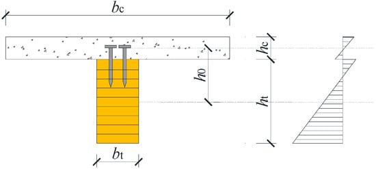
Figure 1.
Cross-section and stress distribution of TCC beams.
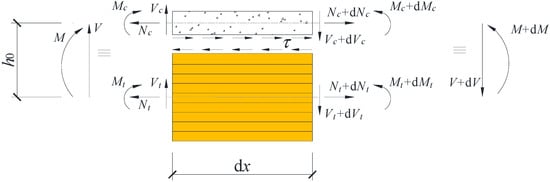
Figure 2.
Force analysis on a differential segment of TCC beams.
Geometric compatibility requires that the interfacial slip s equals the difference in axial displacements of the centroids minus the relative displacement caused by sectional rotation:
where ut and uc denote the axial displacements of the timber and concrete centroids, h0 denotes the distance between centroids, and θ denotes the section rotation.
Differentiating Equation (5) with respect to the longitudinal coordinate x and substituting the kinematic relation yields the slip gradient:
where εt and εc denote the axial strain of the timber and concrete centroids, respectively, derived from the constitutive laws (Equations (1) and (2)) and axial force definitions:
where A is the cross-sectional area.
Substituting Equation (7) into Equation (6) provides the compatibility equation linking slip gradient, axial forces, and curvature:
Utilizing the axial force equilibrium (Equation (9)) and noting that represents the distance between the centroids (), the total moment expression (Equation (11)) simplifies to
Applying the shear connection constitutive relation (Equation (4)) to the shear flow equilibrium (Equation (10)) and differentiating once with respect to x yields
Substituting the compatibility relation for ds/dx (Equation (8)) and axial force equilibrium (Equation (9)) into Equation (13) gives the governing equation for the timber axial force:
The curvature κ can be expressed in terms of the total moment M and the timber axial force Nt by combining the component moment–curvature relations (Equation (3)) with the total moment expression (Equation (12)):
The governing differential equation for curvature κ is derived by differentiating Equation (15) twice with respect to x:
Substituting the expression for from Equation (14) and the expression for from Equation (15) into Equation (16), followed by rearrangement, yields
where , , and . Parameters and are the bending stiffnesses of TCC beam sections corresponding to no and full composite action, respectively.
2.3. Analytical Solution of Differential Equation
The governing differential equation for curvature (Equation (17)) can be analytically solved based on actual loading and boundary conditions. This study employs third-point loading and uniformly distributed loading (UDL) to replicate fundamental physical actions in timber–concrete composite floors. Third-point loading simulates concentrated forces from secondary beam reactions at critical sections, capturing load transfer mechanisms under conditions dominated by point loads, while UDL models combined permanent dead loads and sustained service loads, characterizing distributed effects from self-weight and service requirements.
2.3.1. Third-Point Loading Condition
As illustrated in Figure 3a, a TCC beam of span l is subjected to two symmetric point loads P at third points. Due to symmetry, we analyze the right half (0 ≤ x ≤ l/2). The bending moment distribution is piecewise linear:
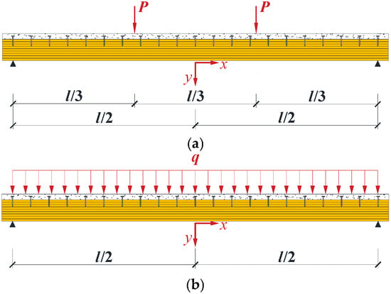
Figure 3.
Computational schemes of TCC beams under different loading conditions: (a) third-point loading condition; (b) uniformly distributed loading condition.
Substituting Equation (18) into Equation (17) yields two coupled ODEs:
The homogeneous + particular solutions to Equation (19) yield
Four conditions determine integration constants
- Mid-span symmetry ;
- Support moment release ;
- Curvature continuity ;
- Shear flow continuity (Take the first derivative of Equation (15) and substitute the shear flow () continuity condition to obtain).
The integration constants are solved as follows:
2.3.2. Uniformly Distributed Loading Condition
As illustrated in Figure 3b, a TCC beam with a span of l is subjected to a uniformly distributed load q. Due to symmetry, only the right half-span (0 ≤ x ≤ l/2) is analyzed. The bending moment distribution is as follows:
Substituting Equation (22) into Equation (17) yields the following ODE:
The homogeneous + particular solution to Equation (23) yields
Two conditions determine integration constants
- Mid-span symmetry ;
- Support moment release .
The integration constants are solved as follows:
2.4. Deflection Calculation Using the Conjugate Beam Method
Given the analytical solution for curvature distribution in the TCC beam, the distribution equation of bending stiffness can be derived from Equation (26).
Although the deflection distribution could theoretically be obtained by double integration of the curvature function, the process involves complex analytical integration. Therefore, this study employs the conjugate beam method to compute beam deflections.
In the conjugate beam method, the curvature distribution κ(x) is treated as an equivalent distributed line load on a conjugate beam. The beam span l is divided into n equidistant intervals, and the curvature value at the midpoint xi of each interval is denoted as κ(xi), where i = 1, 2, …, n. Each κ(xi) is assumed to be uniformly distributed over the corresponding interval of the conjugate beam.
According to the conjugate beam principle, the bending moment at any cross-section of the conjugate beam under the above loading condition is equal to the deflection of the original beam at that cross-section.
It should be noted that increasing the number of intervals n improves the accuracy of the discrete load approximation, bringing it closer to the actual curvature distribution and thereby enhancing the precision of the deflection results.
3. Results and Discussion
Distribution of Bending Stiffness
The design parameters of TCC beam specimens GCCB1–3 from reference [27] were selected to calculate the bending stiffness under third-point loading and uniformly distributed loading (UDL), respectively. Specimens GCCB1–3 represent TCC beams with screw spacing of 100 mm, 250 mm, and 400 mm, respectively. The bending stiffness calculated from the analytical solution for curvature is presented in Figure 4a,b. It can be observed that due to interfacial slip, the bending stiffness of the TCC beam varies along the span. Under third-point loading, the bending stiffness decreases monotonically from the mid-span toward the load application points, and then increases monotonically from these points toward the supports. In contrast, under UDL, the stiffness reaches its maximum at the mid-span and gradually decreases toward the supports. Altering the spacing of shear connectors affects both the magnitude and the distribution pattern of the bending stiffness. As the connector spacing decreases—enhancing composite action—the non-uniformity of the bending stiffness distribution becomes more pronounced. However, the bending stiffness distribution under UDL is more uniform compared to that under third-point loading. Conclusively, the distribution of bending stiffness along the cross-section of the TCC beam depends not only on the arrangement of shear connectors but also significantly on the loading condition. This is because the internal force distribution in shear connectors varies along the span under different loading scenarios, ultimately leading to differing patterns in the bending stiffness distribution.
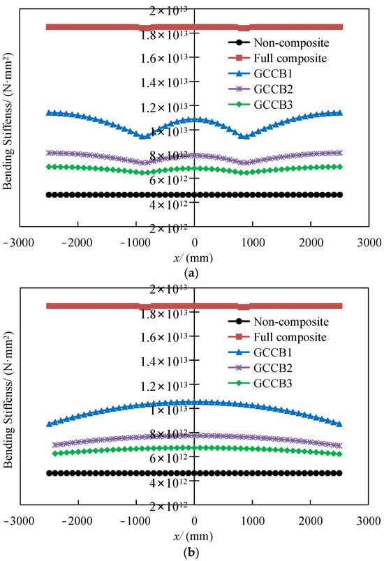
Figure 4.
Distribution of bending stiffness along the span of TCC beams: (a) third-point loading; (b) uniformly distributed loading.
Figure 5 compares the bending stiffness from the analytical solution proposed in this paper, the effective bending stiffness calculated according to Eurocode 5, and the equivalent bending stiffness back-calculated from experimentally measured mid-span deflections. The calculation employs the service load that induces l/250 mid-span deflection in the composite beam, corresponding to the serviceability limit state (SLS). It is evident that all experimental data fall within the range predicted by the present analytical method. Furthermore, the effective bending stiffness calculated according to Eurocode 5 shows acceptable agreement with the test results, with relative errors less than 4%.
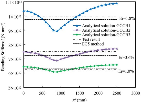
Figure 5.
Comparison between theoretical and experimental bending stiffness.
To further validate the accuracy of both the conjugate beam method—using analytical curvature solutions—and the simplified approach in Eurocode 5, mid-span deflections of the TCC beams at the serviceability limit state are computed and compared, as summarized in Table 1. The TCC beam specimens cited in references [27,28] were all subjected to third-point loading, which is the reason why they were selected. Theoretically, the conjugate beam method accounts for the variation in bending stiffness, whereas Eurocode 5 employs a single representative bending stiffness. The results show that both methods—whether based on the conjugate beam method applied to the analytical curvature distribution or the simplified approach in Eurocode 5—achieved 99% average accuracy in predicting the mid-span deflection of TCC beams. This indicates that although the Eurocode 5 formula was originally derived for semi-sinusoidal loading conditions, it remains sufficiently accurate for predicting the mid-span deflection under third-point loading conditions. The accuracy of theoretical prediction critically depends on the selected connector stiffness value. However, this study focuses on deflection behavior under the ULS, where connectors remain predominantly elastic. Based on experimental data from reference [27,28], the shear stiffness (kser) of connectors is determined for computational purposes. The observed close agreement between theoretical predictions and experimental results may be attributed to the relatively common conditions of the numerical example: concentrated loads were applied at locations moderately distant from supports and the bending stiffness at loading points from the calculation results was only 5–15% lower than at mid-span. Consequently, further research employing experimental testing or finite element analysis is recommended to rigorously evaluate the accuracy of the curvature-based conjugate beam method and the γ-method under extreme loading conditions.

Table 1.
Comparison between theoretical and experimental mid-span deflections of TCC beams.
By leveraging numerical computation tools such as MATLAB (R2024b), the conjugate beam method allows for precise determination of mid-span deflection under arbitrary loading conditions, with increasing accuracy achieved as the number of discretized segments (n) increases. However, from an engineering design perspective, the Eurocode 5 method offers a favorable balance between accuracy and practical simplicity, making it highly suitable for structural analysis and design applications.
It should be noted that, given the material properties and cross-sectional dimensions, the distribution of sectional stiffness in TCC beams is primarily determined by connector arrangement and loading conditions. Although the connector spacing (100–400 mm) in the provided examples (Table 1) covers the typical range used in practical engineering, when the loading point is much closer to the support than in these examples, the interface slip effect will induce significant stiffness reduction near the loading point. This extreme non-uniformity may lead to deflection at the loading point exceeding that at the mid-span. For practical design applications, deflection verification at loading points—particularly those positioned near supports—must be performed using either (a) the curvature-based conjugate beam method (implemented in this study using MATLAB), providing high-fidelity results for critical applications, or (b) conservative local stiffness reduction models based on the γ-method, though these require further parametric study for rigorous development. In addition, local deformation risks can be mitigated by densifying shear connectors within a specified range symmetrically around the loading point.
The analytical solution proposed in this paper relies on simply supported boundaries and symmetric loading. Its extensibility to continuous beams and asymmetric loading needs to be verified in future research.
4. Conclusions
- The distribution of bending stiffness in TCC beam sections depends not only on the arrangement of shear connectors but is also closely related to the loading conditions. Under third-point loading, the bending stiffness decreases monotonically from the mid-span toward the load application points and increases monotonically from the loading points toward the supports; under uniformly distributed loads, the bending stiffness reaches its maximum at the mid-span and gradually decreases toward the supports.
- As the spacing between shear connectors decreases, the degree of composite action increases, leading to a greater non-uniformity in the distribution of bending stiffness. However, under uniformly distributed loads, the stiffness distribution tends to be more uniform compared to that under third-point loading, indicating a more balanced structural response along the span.
- Comparison with experimental results demonstrates that both the conjugate beam method based on the analytical solution of curvature distribution and the simplified approach specified in Eurocode 5 can accurately predict the mid-span deflection of TCC beams, validating their applicability in practical engineering analysis and design. In addition, careful attention must be paid to the deflection values at loading points, particularly when the loading position is close to the supports.
Author Contributions
Conceptualization, Y.J. and X.H.; methodology, Y.J. and X.H.; validation, Y.J.; investigation, Y.J.; data curation, Y.J.; writing—original draft preparation, Y.J.; writing—review and editing, Y.J. and X.H.; visualization, Y.J.; supervision, X.H.; funding acquisition, Y.J. All authors have read and agreed to the published version of the manuscript.
Funding
This research was funded by the Natural Science Research of Jiangsu Higher Education Institutions of China (22KJD560006) and the Qinglan Project of Jiangsu Province of China.
Data Availability Statement
The data presented in this study are available on request from the corresponding author.
Conflicts of Interest
The authors declare no conflicts of interest.
Abbreviations
The following abbreviations are used in this manuscript:
| TCC | Timber–concrete composite |
| ULD | Uniformly distributed loading |
| Cov | Coefficient of variation |
References
- Yeoh, D.; Fragiacomo, M.; Franceschi, M.D.; Boon, K.H. State of the art on timber-concrete composite structures: Literature review. J. Struct. Eng. 2011, 137, 1085–1095. [Google Scholar] [CrossRef]
- Jiang, Y.; Hu, X.; Liu, Y.; Tao, L. Long-term performance of glulam-lightweight concrete composite beams with screw connections. Constr. Build. Mater. 2021, 310, 125227. [Google Scholar] [CrossRef]
- Mirdad, M.A.H.; Khan, R.; Chui, Y.H. Analytical Procedure for Timber-Concrete Composite (TCC) System with Mechanical Connectors. Buildings 2022, 12, 885. [Google Scholar] [CrossRef]
- Estévez-Cimadevila, J.; Martín-Gutiérrez, E.; Suárez-Riestra, F.; Otero-Chans, D.; Vázquez-Rodríguez, J.A. Timber-concrete composite structural flooring system. J. Build. Eng. 2022, 49, 104078. [Google Scholar] [CrossRef]
- Cvetković, R.; Ranković, S.; Mišulić, T.K.; Kukaras, D. Experimental analysis of mechanical behavior of timber-concrete composite beams with different connecting systems. Buildings 2023, 14, 79. [Google Scholar] [CrossRef]
- Otero-Chans, D.; Suárez-Riestra, F.; Martín-Gutiérre, E.; Estévez-Cimadevila, J. Experimental and numerical analysis of a full-scale timber-concrete-composite beam from simply supported to frame-connected. Eng. Struct. 2025, 327, 119624. [Google Scholar] [CrossRef]
- Kozarić, L.; Varju, Đ.; Purčar, M.V.; Bursać, S.; Čeh, A. Experimental investigations and numerical simulations of the vibrational performance of composite timber-lightweight concrete floor structures. Eng. Struct. 2022, 270, 114908. [Google Scholar] [CrossRef]
- Ogrin, A.; Hozjan, T. Fire resistance of timber-concrete composite slabs: A simplified method. Mater. Struct. 2020, 53, 106. [Google Scholar] [CrossRef]
- Zhang, X.; Hu, X.; Gong, H.; Zhang, J.; Lv, Z.; Hong, W. Experimental study on the impact sound insulation of cross laminated timber and timber-concrete composite floors. Appl. Acoust. 2020, 161, 107173. [Google Scholar] [CrossRef]
- Liu, J.; Fischer, E.C.; Barbosa, A.R.; Sinha, A. Experimental testing and numerical simulation of timber-concrete composite floors in fire. J. Struct. Eng. 2023, 149, 04023151. [Google Scholar] [CrossRef]
- Wang, Z.; Wei, Y.; Hu, Y.; Chen, S.; Zhao, K. An Investigation of the Flexural Performance of Bamboo-Concrete Composite Beams with Precast Light Concrete Slabs and Dowel Connectors. J. Build. Eng. 2021, 41, 102759. [Google Scholar] [CrossRef]
- Du, H.; Chen, B.; Chen, Z.; Wei, Y.; Hu, X. Study on flexural performance of glued laminated bamboo and timber-concrete composite beams. Constr. Build. Mater. 2025, 492, 142986. [Google Scholar] [CrossRef]
- Hu, Y.; Wei, Y.; Chen, S.; Yan, Y.; Zhang, W. Experimental Study on Timber–Lightweight Concrete Composite Beams with Ductile Bolt Connectors. Materials 2021, 14, 2632. [Google Scholar] [CrossRef] [PubMed]
- Khorsandnia, N.; Valipour, H.R.; Crews, K. Experimental and analytical investigation of short-term behaviour of LVL-concrete composite connections and beams. Constr. Build. Mater. 2012, 37, 229–238. [Google Scholar] [CrossRef]
- Fernandes, F.P.; Dias, A.A.; Neto, J.M. Experimental and numerical analysis on timber-concrete connections with glued reinforcing bars. Eng. Struct. 2023, 277, 115437. [Google Scholar] [CrossRef]
- Tao, H.; Shi, B.; Yang, H.; Wang, C.; Ling, X.; Xu, J. Experimental and finite element studies of prefabricated timber-concrete composite structures with glued perforated steel plate connections. Eng. Struct. 2022, 268, 114778. [Google Scholar] [CrossRef]
- Mirshekar, S.; Sadeghian, V. Evaluating the behavior of notched connections in timber-concrete composite beams. Structures 2025, 81, 110146. [Google Scholar] [CrossRef]
- Yan, Z.; Wei, Y.; Du, H.; Chen, J.; Ding, M.; Li, G. Experimental and theoretical study on flexural performance of reinforced bamboo-concrete composite beams. Eng. Struct. 2025, 325, 119503. [Google Scholar] [CrossRef]
- Fragiacomo, M. Experimental behaviour of a full-scale timber-concrete composite floor with mechanical connectors. Mater. Struct. 2012, 45, 1717–1735. [Google Scholar] [CrossRef]
- Augeard, E.; Michel, L.; Ferrier, E. Experimental and analytical study of the mechanical behavior of heterogeneous glulam-concrete beams and panels assembled by a specific treatment of wood. Constr. Build. Mater. 2018, 191, 812–825. [Google Scholar] [CrossRef]
- Negrão, J.H.J.O.; Maia de Oliveira, F.M.; Leitão de Oliveira, C.A.; Cachim, P.B. Glued composite timber-concrete beams. II: Analysis and tests of beam specimens. J. Struct. Eng. 2010, 136, 1246–1254. [Google Scholar] [CrossRef]
- Shi, B.; Zhou, X.; Tao, H.; Yang, H.; Wen, B. Long-term behavior of timber–concrete composite structures: A literature review on experimental and numerical investigations. Buildings 2024, 14, 1770. [Google Scholar] [CrossRef]
- EN 1995-2; Eurocode 5: Design of Timber Structures-Part 2: Bridge. CEN (European Committee for Standardization): Brussels, Belgium, 2005.
- Möhler, K. On the load carrying behavior of beams and columns of compound sections with flexible connections. Ph.D. Thesis, Karlsruhe Institute of Technology, Karlsruhe, Germany, 1956. [Google Scholar]
- EN 1995-1-1; Eurocode 5: Design of Timber Structures-Part 1.1: General Rules and Rules for Buildings. CEN (European Committee for Standardization): Brussels, Belgium, 2005.
- Ceccotti, A. Timber-concrete composite structures. In Timber Engineering STEP 2; Centrum Hout: Almere, The Netherlands, 1995; pp. E13/1–E13/12. [Google Scholar]
- Jiang, Y. Mechanical Behaviour and Design Methods of Glulam-Lightweight Concrete Composite Beams. Ph.D. Thesis, Nanjing Tech University, Nanjing, China, 2018. (In Chinese) [Google Scholar]
- Wang, Y. Study on Mechanical Performance of Timber Concrete Composite Beams. Master’s Thesis, Nanjing Tech University, Nanjing, China, 2012. (In Chinese) [Google Scholar]


Disclaimer/Publisher’s Note: The statements, opinions and data contained in all publications are solely those of the individual author(s) and contributor(s) and not of MDPI and/or the editor(s). MDPI and/or the editor(s) disclaim responsibility for any injury to people or property resulting from any ideas, methods, instructions or products referred to in the content. |
© 2026 by the authors. Licensee MDPI, Basel, Switzerland. This article is an open access article distributed under the terms and conditions of the Creative Commons Attribution (CC BY) license.