Abstract
U-shaped steel−concrete composite beams (USCCBs) have been widely used in civil engineering due to their numerous advantages, including high load-bearing capacity, high rigidity, good ductility, short construction periods, and compatibility with the development of prefabricated buildings. In particular, USCCBs have been increasingly applied to super high-rise buildings and extra-large span bridges. Over the past decade or so, many new types of shear connectors and structural forms for USCCBs have been developed. Meanwhile, significant progress has been achieved in research on the flexural, shear, torsional, and fire-resistance performance of USCCBs, the seismic behavior of beam−column joints, and the strengthening of concrete beams with U-shaped steel casings. Nevertheless, challenges and limitations remain in both experimental research and practical applications. This paper presents a systematic review of recent research advances in USCCBs. Existing problems, development prospects, and future research priorities are comprehensively summarized and discussed, with the aim of further promoting the development and engineering application of USCCBs.
1. Introduction
U-shaped steel−concrete composite beams (USCCBs) are novel structural components developed based on traditional steel−concrete composite beams. They consist of an externally U-shaped steel casing and a concrete or reinforced concrete (RC) beam enclosed within it, typically cast in situ together with the upper concrete slab. The two components are connected by shear connectors to form a composite beam with a T-shaped cross-section, as shown in Figure 1. On the one hand, the U-shaped steel casing serves as permanent formwork, thereby reducing formwork requirements during construction. Moreover, as the U-shaped steel participates in load bearing, the demand for reinforcing steel can be reduced. On the other hand, the concrete infill restrains inward buckling of the thin-walled U-shaped steel web, while the confinement provided by the U-shaped steel casing enhances the mechanical performance of the concrete. Previous studies showed that USCCBs exhibit numerous advantages, including high load-bearing capacity, high stiffness, excellent ductility, and good fire resistance, and they are regarded as one of the most recent advancements in steel−concrete composite beams [1]. Furthermore, USCCBs enable greater spans while mitigating issues such as excessive relative slip at the interface between concrete and steel plates, as well as insufficient lateral stability. Consequently, USCCBs have attracted extensive attention from researchers since their introduction.
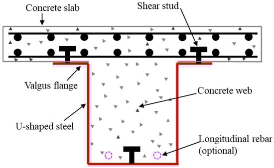
Figure 1.
Schematic of a U-shaped steel−concrete composite beam.
The design concept of USCCBs was first proposed by Oehlers et al. [2] in the early 1990s. Following subsequent refinements by other researchers, the current USCCB configuration was gradually established [3,4,5,6]. Generally speaking, U-shaped steel casings are fabricated using three methods, namely, cold forming, welding, and bolt fastening, as shown in Figure 2. Among these methods, cold forming provides superior structural integrity and is well-suited to industrial production. In contrast, welding and bolt fastening offer greater flexibility, allowing base and web plates of different thicknesses, steel grades, and geometries to be selected according to design requirements. However, thin-walled steel plates are prone to burn-through during welding or when welding shear connectors, and residual welding stresses may also be introduced. In comparison, bolt fastening facilitates on-site construction and better meets the requirements of the development of prefabricated buildings. In addition, bolts can enhance the connection at the steel−concrete interface, playing a role similar to that of shear studs. According to the configurations of the top flanges, U-shaped steel can be classified into two types: valgus flanges and varus flanges. Dong [7] found that varus flanges are more reasonable than valgus flanges, exhibiting superior performance in slip resistance and web stability. However, Wu et al. [8] indicated that valgus flanges are more favorable for concrete casting. Compared with varus flanges, valgus flanges increase the interface area between the concrete slab and the beam rib, thereby enhancing the longitudinal shear resistance of the composite beams. During the first two decades of research, extensive investigations were conducted on the flexural, shear, and torsional behaviors of USCCBs, as well as the seismic performance of beam−column joints, achieving substantial research progress [9,10,11,12,13,14]. Over the past decade, a variety of novel shear connectors and structural configurations for USCCBs have been proposed. Meanwhile, further advances have been achieved in beam−column joints and in the strengthening of RC beams with U-shaped steel casings. Despite these developments, challenges and limitations remain in both experimental studies and practical applications. To date, comprehensive review articles on the research advances in the development of USCCBs are still relatively scarce, which limits researchers’ ability to quickly grasp the current research status and emerging development trends in this field.
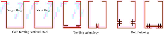
Figure 2.
Processing technologies of U-shaped steel.
In this context, this paper presents a comprehensive review and summary of the latest research findings on USCCBs over the past decade. The flexural and shear performance, types of shear connectors, beam−column joints of USCCBs, and the strengthening of RC beams using U-shaped steel casings are discussed in detail. In addition, issues related to fire resistance, torsional resistance of USCCBs, and local buckling of thin-walled U-shaped steel plates are systematically addressed. The purpose of this paper is not only to review the significant research achievements of USCCBs in the aforementioned fields, but more importantly, to summarize the challenges identified in existing experimental research and practical applications. These challenges primarily include the impact on the flexural performance of USCCBs after the application of high-strength materials, recycled concrete, and embossed steel or corrugated steel plates, the issue of local buckling in thin-walled U-shaped steel webs, and the optimization design of novel shear connectors and beam−column joints, as well as the promotion and application of the U-shaped steel strengthening technique in engineering projects. Finally, existing research gaps and unresolved problems are identified, and future research directions are proposed, with the aim of providing a useful reference for the further development and engineering application of USCCBs.
2. Mechanical Performance of USCCBs
As a typical flexural member, USCCBs are subjected to both bending moments and shear forces. Accordingly, the flexural behavior of normal sections and the shear behavior of inclined sections are the primary focuses of research. In certain applications, such as canopy beams and edge beams in frame structures, these members are also subjected to torsional actions. Additionally, thin-walled U-shaped steel webs are prone to local buckling under relatively high compressive stresses, and preventing local buckling from occurring prior to steel yielding remains an important research topic. In view of the aforementioned mechanical performances of USCCBs, this section reviews relevant research advances obtained over the past decade and discusses the fire-resistance performance of such composite beams.
2.1. Flexural Behavior
For conventional USCCBs, flexural tests indicated that when the U-shaped steel and concrete work effectively together under positive bending moments, they fail in flexure of the normal section. This failure mode is characterized by yielding of the U-shaped steel at mid-span and crushing of the top concrete slab, demonstrating excellent load-bearing capacity and ductility. In this case, the formula for calculating the bending capacity based on the simplified plastic theory has relatively high accuracy and is generally conservative [15]. Under negative bending moments, the U-shaped steel base plate and the infilled concrete are subjected to compression together. The infilled concrete provides out-of-plane restraint to the U-shaped steel base plate, thereby suppressing its local buckling. Conversely, the U-shaped steel also confines the infilled concrete. This mutual confinement further enhances the sectional flexural stiffness and load-bearing capacity of the USCCBs under negative bending moments [16]. Studies [17,18,19] showed that under negative bending moments and with full shear connection, USCCBs also experience flexural failure at the normal section. The damage is primarily characterized by tensile cracking of the concrete flanges, fully developed cracks at the mid-span, and local buckling of the U-shaped steel. Similarly, the formula for calculating the flexural capacity of USCCBs under negative bending moments, developed based on simplified plastic theory, also demonstrates high accuracy [20,21]. For the USCCBs formed by bolt fastening [22], their flexural behaviors depend largely on the buckling mode of the U-shaped steel base plates. In practical engineering, bolt spacing should be appropriately designed. Furthermore, studies showed that increasing the thickness of the U-shaped steel plate, the diameter of the longitudinal reinforcement within the concrete slab, or the diameter of the longitudinal reinforcement at the bottom of the RC beam can significantly enhance the ultimate flexural capacity of USCCBs under negative bending moments. Among these factors, the thickness of the U-shaped steel plate has the most pronounced effect [23,24].
Over the past decade, to better meet the construction requirements of super-tall buildings and long-span bridges, as well as to support the implementation of the dual-carbon strategy, the application of high-strength materials, prestressing technologies, and recycled concrete to USCCBs has emerged as a new direction of development.
2.1.1. Application of High-Strength Materials
In recent years, USCCBs have been increasingly applied in super-tall buildings, such as the Block F2-4 of Guangzhou Pearl River New Town [25] and the Crystal Tower in South Korea, and long-span bridges. To further enhance the mechanical performance of the composite beams while reducing their cross-sectional dimensions and the overall weight, some researchers proposed incorporating lightweight and high-strength construction materials in USCCBs. Cao et al. [26,27] combined the complementary advantages of high-strength steel and high-strength concrete to conduct research on the flexural behaviors of high-strength USCCBs. The results indicated that compared with conventional USCCBs, high-strength USCCBs can achieve an increase in the flexural capacity by over 60%. However, their ductility reduces as the strength of the U-shaped steel increases. Subsequently, Ren et al. [28] and Li et al. [29] further investigated the effects of cross-sectional dimensions and material strength, with particular emphasis on the ductility of high-strength USCCBs. Adopting moderately lower strength U-shaped steel in combination with higher-strength concrete was recommended, provided that the required load-bearing capacity was satisfied. Kim et al. [30] emphasized that when high-strength steel is used for the U-shaped steel, the potential reduction in ductility resulting from the increased steel strength must be carefully considered.
2.1.2. Application of Prestressing Technology
Prestressing technology can effectively control the crack width and deflection in concrete flexural members, fully utilize the mechanical properties of high-strength concrete and high-strength steel, and enhance the fatigue resistance of the components while offering good economic benefits. Consequently, some researchers proposed applying prestressing technology to USCCBs. Yu [31] conducted experimental tests on cold-formed U-shaped steel−concrete composite continuous beams with prestressed reinforcement. The research found that USCCBs underwent typical flexural failure under positive bending moments. Upon application of prestressing technology, both load-bearing capacity and stiffness were significantly enhanced. Conversely, under negative bending moments, cracking of the concrete slab occurred at an early stage. At failure, both the top and bottom flanges of the U-shaped steel yielded, while the web section only partially yielded, and the prestressed reinforcement remained in the elastic state throughout the loading process. Additionally, analytical formulas were established for predicting the load-bearing capacity, deformation, relative interface slip, and shear lag effects. Liu et al. [32] proposed an improved cold-formed U-shaped steel-constrained prestressed RC beam, drawing on the working principles of concrete-filled steel tubular (CFST) columns. This research revealed that this composite beam underwent flexural failure and that partial confinement of the concrete transformed the brittle failure of the concrete in the compression zone into ductile failure, thereby significantly enhancing ductility. Compared with conventional RC beams and prestressed concrete (PC) beams, the load-bearing capacity was increased from 5% to 10%.
2.1.3. Application of Recycled Concrete
Recycled concrete enables resource utilization of construction waste, reduces the extraction of natural sand and gravel, and brings about significant environmental benefits. In recent years, some studies explored the use of recycled concrete in USCCBs. Wu [33] and Ji [34] placed waste concrete blocks together with freshly mixed concrete within thin-walled U-shaped steel, and through mixing and vibration produced thin-walled U-shaped steel-recycled concrete composite beams. The results showed that when the replacement ratio of waste concrete blocks was between 25% and 40%, the load−deflection curves of the test specimens were very close to those of fully cast-in-situ concrete specimens. Moreover, the placement of longitudinal reinforcement at the beam bottom effectively reduced the slip at the steel−concrete interface and was more effective in enhancing both sectional stiffness and load-bearing capacity than increasing the steel plate thickness. Their study further revealed that, for a similar total steel usage, U-shaped steel-recycled concrete composite beams exhibited flexural capacity comparable to that of RC beams, along with superior overall performance. Dang [35] discovered that USCCBs made from recycled concrete are more prone to brittle failure than those made from conventional concrete. Increasing the strength of recycled concrete can simultaneously enhance the flexural capacity and ductility of the composite beams. However, as the replacement ratio of recycled aggregates increases, both the flexural capacity and ductility of the composite beams gradually decrease.
2.1.4. Application of Corrugated Steel and Embossed Steel Plate
In addition to the aforementioned research, researchers investigated the influence of using rectangular and trapezoidal corrugated steel as the U-shaped steel base plates, as well as the effect of the number of corrugations on the flexural performance of composite beams [36]. The results showed that compared with conventional USCCBs, the use of corrugated steel plates as base plates significantly enhances the load-bearing capacity. Furthermore, rectangular corrugated steel plates outperform trapezoidal ones, and an increase in the number of corrugations leads to higher load-bearing capacity. To address the reduction in flexural capacity caused by local buckling of thin-walled U-shaped steel plates and the poor manufacturability of corrugated steel plates, some researchers proposed replacing embossed steel plates with U-shaped webs [37]. The results indicated that all the specimens undergo flexural failure in general, with local deformation also observed in the embossed steel webs. The contribution of the embossed steel webs to bending resistance is significantly lower than that of the ordinary steel webs, yet the specimens using embossed steel webs exhibit superior ductility.
2.2. Shear Behavior
It is well known that the shear span ratio is a significant factor influencing the shear failure mode of composite beams. Yang et al. [38] revealed that specimens with shear span ratios of 0.9 and 1.1 all experienced diagonal compression failure. Zhao et al. [39] found that when the shear span ratio λ was 1, the specimen experienced diagonal compression failure, while when λ was 1.5, the specimen underwent shear-compression failure. Subsequently, Ding [40] conducted shear tests on U-shaped steel−concrete composite deep beams and found that although these beams exhibited better ductility than that of conventional USCCBs, diagonal compression failure still occurred. Moreover, the mechanical performance of the U-shaped steel could not be fully utilized under negative bending moments. Apart from the shear span ratio, the thickness of the U-shaped steel web, the width of the concrete slab, and the longitudinal reinforcement at the bottom of the RC beam, stirrups and shear studs also have significant effects on the shear behaviors of USCCBs. As the steel ratio increases, the shear resistance of USCCBs significantly improves. However, once the effective shear width is exceeded, further increasing the width of the concrete slab will actually reduce the ductility of the specimens. Welding shear studs to the U-shaped steel base plate only has a relatively minor influence on shear capacity, whereas welding shear studs to the U-shaped steel base plate or providing longitudinal reinforcement at the bottom of the concrete beams can effectively enhance the ductility of USCCBs.
At present, both Chinese and international standards adopt plastic theory to calculate the shear capacity of composite beams and conservatively neglect the beneficial contribution of the concrete slab. Lin [21] and Ding [40] respectively employed the superposition principle to express the shear capacity of USCCBs as the sum of the shear capacity of the U-shaped steel web and the infilled concrete. The calculation formula is shown in Equation (1):
where Vu represents the shear capacity of USCCB, Vcu is the shear capacity of the infilled concrete, and Vsu is the shear capacity of the U-shaped steel web. It is noteworthy that since the infilled concrete is encased by U-shaped steel, there is a certain confinement effect, which will enhance the shear strength of the infilled concrete to some extent. Equation (1) does not account for the composite action of the U-shaped steel and the infilled concrete. In addition, it is essential to ensure a good adhesion at the steel−concrete interface. Once the two parts separate, this formula will no longer be applicable, and the shear capacity will be significantly reduced. Tian [41] pointed out that when stirrups are provided, their contribution to shear resistance should be taken into account, as shown in Equation (2):
where Vsvu is the shear capacity of the stirrups. Furthermore, different types of shear connectors lead to different shear capacity calculation models. For web-embedded USCCBs proposed by Yang et al. [38], the shear capacity is contributed by the U-shaped steel web, the dowel action of the longitudinal reinforcement at the bottom of the RC beam, and the concrete, as shown in Equation (3):
Vu = Vcu + Vsu
Vu = Vcu + Vsu +Vsvu
Vu = Vc + Vsu +VD
Unlike Equations (1) and (2), Equation (3) accounts for the beneficial contribution of the concrete slab. Here, Vc is the sum of the shear capacity of the concrete flange and web, while VD denotes the shear capacity generated by the dowel action of the longitudinal reinforcement. Additionally, Equation (3) assumes that the U-shaped steel web does not undergo local buckling before yielding, and no relative slip occurs between the longitudinal reinforcement and the infilled concrete. For the rebar truss stiffened USCCB proposed by Zhao et al. [39], the shear capacity is jointly provided by the U-shaped steel web, the concrete web, the concrete flange, and the dowel action, as shown in Equation (4):
Vu = VCw + VCf +Vsu +VD
Here, the beneficial contribution of the concrete slab is also considered, but the shear capacity of the concrete flange VCf and that of the concrete web VCw are calculated separately. It should be noted that a reduction coefficient, influenced by shear connection degree, is introduced when calculating the shear capacity generated by the dowel action. For this type of USCCB, the value is usually taken as 0.6. Additionally, both Equations (3) and (4) neglect the contribution of reinforcement in the concrete slab.
2.3. Torsional Behavior
Research on the torsional behaviors of USCCBs remains relatively limited. When USCCBs are used in bridge engineering, torsional effects induced by transverse wind loads, vehicle sway, or eccentric loads from multiple traffic lanes cannot be neglected. Zhao et al. [42] transformed the open U-shaped steel section into an equivalent closed box-shaped section by welding a steel truss to the varus flange of the U-shaped steel. This configuration significantly enhanced the torsional stability of the U-shaped steel and its confinement effect on the infilled concrete. The results showed that the torsional failure of USCCBs was characterized either by the critical diagonal crack penetrating the concrete slab surface or by crushing of the concrete in the compression zone near the critical diagonal crack at the top (bottom) surface of the concrete slab. The cracking torque was approximately 31% to 44% of the ultimate torque. With an increase in the width and thickness of the concrete slab and the depth of the web plate, the elastic stiffness, cracking torque, and ultimate torque of USCCBs gradually increased. Moreover, calculation formulas for elastic stiffness, cracking torque, and ultimate torque were established. Turetta et al. [43] investigated the torsional instability of U-shaped steel beams without lateral supports during the construction stage (i.e., without concrete infill), which are prone to lateral torsional buckling. The behavior of the U-shaped steel web being distorted due to the self-weight of the concrete was specifically examined in their research. The results indicated that the self-tapping screws used for assembling U-shaped steel beams did not exhibit failure or significant deformation, whereas open U-shaped steel sections were susceptible to global instability due to lateral torsion. The use of the buckling design curve “b”, as recommended by EN 1993 [44] for the evaluation of torsional buckling moments, was found to be sufficiently conservative. Yang et al. [45] conducted experimental investigations into the torsional behaviors and failure modes of the web-embedded USCCBs. Their study found that the torsional failure was characterized by the concrete crushing between the critical cracks near the beam ends. However, the U-shaped steel web remained within the elastic range and retained a considerable reserve of deformation capacity. Moreover, the width of the concrete flange, the height of the concrete web, the thickness of the concrete slab, and the U-shaped steel web were identified as the main parameters influencing the torsional behaviors. In addition, Yang et al. [46] investigated the failure modes of web-embedded USCCBs subjected to combined bending and torsion and explored the effects of the bending moment-to-torque ratio, the thickness of the concrete flange, and the height of the concrete web on the bending−torsion performance.
2.4. Stability Analysis of U-Shaped Steel Web
In composite beams with a relatively small shear span ratio, the shear span regions are subjected to significant compressive stresses, particularly at the supports where the thin-walled U-shaped steel plates are prone to local buckling under compression. In addition, under negative bending moments, local buckling is also likely to occur. This will prevent the full utilization of material properties and lead to a reduction in the load-bearing capacity of USCCBs [47,48]. To prevent the occurrence of elastic buckling prior to steel yielding, some researchers conducted investigations into the local stability of thin-walled U-shaped steel plates. Ipe et al. [49] calculated the buckling stresses of the U-shaped steel webs, considering a web height-to-thickness ratio of 42.5 to ensure that the buckling stresses remained substantially higher than the yield stress. Consequently, local buckling of the steel plate occurred only after yielding of the U-shaped steel in all tested specimens. Zhou et al. [50] preliminarily proposed a recommended limit for the web height-to-thickness ratio (≤100) of U-shaped steel to prevent local buckling failure before the peak load was reached. However, this recommendation lacks rigorous theoretical justification and requires further investigation. Zhou et al. [51] suggested that the web height-to-thickness ratio limits for U-shaped steel can be determined according to the “GB 50017-2003 Code for design of steel structures” [52]. Shen [53] used the small deflection theory to investigate the limit value of the web height-to-thickness ratio for U-shaped steel. Cheng et al. [54] developed a formula for calculating the height-to-thickness ratio limit of U-shaped steel plates using linear regression methods. The research found that nonlinear interactions between the U-shaped steel web and flanges in the compressive zone significantly influence local stability. Therefore, the correlation between the web height-to-thickness ratio of the U-shaped steel and the width-to-thickness ratio of the flanges should be taken into account.
2.5. Fire-Resistant Performance
Owing to the heat absorption effect of the infilled concrete, the surface temperature of the U-shaped steel can be effectively reduced. As a result, the USCCBs demonstrate a marked fire resistance advantage over the conventional H-shaped steel−concrete composite beams [55]. Moreover, after the externally encased U-shaped steel reaches the fire resistance limit, the internal reinforcement can continue to carry the load, providing a relatively high level of structural safety reserve. Over the past decade, notable progress has been made on the fire-resistance performance of USCCBs under the ISO 834 standard fire condition [56]. Gao et al. [57,58] revealed that the load level, the thickness of the fireproof coating, and the height of the U-shaped steel section are the main factors influencing the fire-resistance performance of USCCBs. Ji [34] reported that ignoring the thermal resistance at the interface between the U-shaped steel and the infilled concrete leads to an underestimation of the temperature of the U-shaped steel during a fire and an overestimation of the fire resistance limit of USCCBs. Liu [59] found that the junction between the U-shaped steel base plate and web experiences higher temperature due to exposure to fire on two sides, and that applying fireproof coatings, reducing the load ratio, and incorporating fire-resistant reinforcement can significantly enhance the fire-resistance limit of USCCBs. Furthermore, the incorporation of fire-resistant reinforcement stabilizes the rate of deformation in USCCBs during the heating process. Gao et al. [60] comprehensively examined the effects of the thickness and thermal conductivity coefficient of the fireproof coating, and the thickness of the U-shaped steel plate, and proposed a temperature-based method for calculating the required thickness of fireproof coatings for USCCBs. Yang et al. [61] also found that applying fireproof coatings and providing longitudinal reinforcement at the bottom of concrete beams can significantly enhance the fire resistance of USCCBs. Among them, the fireproof coatings are more economical, but adequate bonding strength between the fireproof coating and the surface of the component must be ensured. Subsequently, the research team further investigated the influence of load ratio and shear connector type on fire-resistance performance [62] and established a formula for calculating the flexural capacity of USCCBs under standard temperature−rise curves.
3. Shear Connectors
For USCCBs, there are usually two potential weak surfaces, namely, the interface between the concrete flange slab and the web of the composite beam (referred to as flange−web interface) and the interface between the U-shaped steel (web and base plate) and the infilled concrete (referred to as steel−concrete interface) (Figure 3). Only when sufficient shear connection strength is ensured at both interfaces can the USCCBs function effectively as an integrated system and fully exploit its mechanical performance. For this purpose, researchers proposed various forms of shear connectors and conducted a series of related studies.
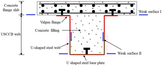
Figure 3.
Two weak surfaces of USCCB.
3.1. Traditional Shear Connectors
To enhance the connection at the flange−web interface and provide sufficient shear resistance and uplift resistance, traditional shear connectors mainly include welding angle steel, channel steel, and shear studs to the top flange of the U-shaped steel, or the use of transverse stirrups penetrating the flange−web interface. Alternatively, combinations of these shear connectors may be employed (Figure 4). To enhance the connection at the steel−concrete interface and prevent excessive bond slip between the two materials, angle steel or shear studs welded to the U-shaped steel web, together with shear studs welded to the U-shaped steel base plate, are typically employed [63].
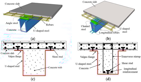
Figure 4.
Traditional shear connectors. (a) Weld angle steel to the valgus flange; (b) weld channel steel to the valgus flange; (c) weld shear studs to the valgus flange; (d) shear studs and transverse stirrups.
Research found that USCCBs incorporating shear connectors (without concrete flange slabs, featuring only steel−concrete interfaces) exhibit a 70.7% increase in shear capacity and a 137.4% improvement in ductility compared to those without shear connectors [49]. When transverse stirrups passing through the flange−web interface and welded to the U-shaped steel base plate are used as shear connectors [64], the composite beams demonstrate favorable mechanical performance. When employing a hybrid shear-resisting method, the use of transverse stirrups penetrating the flange−web interface can reduce the required number of shear studs. In addition, some researchers adopted a hybrid shear-resisting method of welding angle steel to the U-shaped steel web and welding shear studs to the valgus flange [65], thus achieving full shear connection.
Welding shear studs or channel steel to the top flange of U-shaped steel can both provide excellent shear resistance. However, welding a large number of shear studs is labor-intensive, while welding channel steel may impede the arrangement of longitudinal reinforcement in the concrete slab. To overcome these problems and in certain cases ensure the torsional performance of USCCBs, several researchers proposed the angle steel shear connector and obtained an authorized invention patent [66]. Experimental investigations [59,67] showed that the specimens exhibited brittle failure when the angle steel was welded to the U-shaped steel web, whereas they experienced ductile failure when the angle steel was welded to the top flange of the U-shaped steel. Compared with shear studs, angle steel connectors can significantly enhance the flexural performance of USCCBs while reducing construction costs. Some researchers also conducted push-out tests [68] to study the shear resistance and slip behavior of various shear connectors. They found that angle steel connectors welded to the U-shaped steel webs exhibited optimal mechanical performance, whilst also alleviating the congestion issues between the shear connectors and the longitudinal reinforcement within the concrete slab. Moreover, welding angle steel or shear studs to the U-shaped steel web, and embedding them in the concrete, can delay the local buckling of thin-walled steel plates to some extent, thereby enhancing the load-bearing capacity of the components. To reduce the welding process, some researchers have proposed using bolted angle steel instead of welded angle steel as connectors [69]. The results showed that bolted angle steel provides improved ductility, albeit with a slightly lower load-bearing capacity.
It should be noted that although corresponding standards were established for channel steel connectors and shear studs, no specific regulations have yet been made for angle steel connectors. Therefore, further research is needed. Furthermore, the influence of the shear connector spacing should not be overlooked. The research findings showed that as the shear connector spacing increased, both the sectional stiffness and load-bearing capacity of USCCBs decreased, and the failure mode may shift from flexure failure to longitudinal slip failure [8,37]. However, under conditions of full shear connection, a moderate increase in the shear connector spacing can be beneficial for improving the ductility of the specimens.
3.2. Novel Shear Connectors
In response to the shortcomings of traditional shear connectors and to facilitate the wide application of USCCBs, some novel shear connectors have emerged in recent years. Liu et al. [70] welded rebar trusses to the top flanges of the U-shaped steel as shear connectors (Figure 5a), while simultaneously welding shear studs to the U-shaped steel base plate. Moreover, an appropriate amount of longitudinal reinforcement was also provided, which significantly reduced the relative slip at the steel−concrete interface. Liu et al. [50,71] further introduced inverted U-shaped reinforcement to enhance the integrity of the flange−web interface (Figure 5b). They concluded that under this configuration, shear studs welded to the U-shaped steel base plate had a negligible influence on the flexural performance and thus could be omitted. Xu et al. [72] proposed to weld the bottom chord reinforcement of the widely used steel truss composite deck to the top flanges of the U-shaped steel as new shear connectors (Figure 5c). The results showed that specimens using only steel trusses as shear connectors cannot achieve full shear connection and additional appropriate shear studs can be incorporated to enhance the connection at the flange−web interface. Furthermore, Yang et al. [38,73] proposed a web-embedded USCCB (Figure 5d) to achieve full shear connection. The specific construction involves cutting evenly spaced dovetail-shaped grooves at the top of the U-shaped steel web. Then, these grooves were embedded into the concrete slab, forming a web-embedded shear connector with the transverse reinforcement at the bottom of the concrete slab.
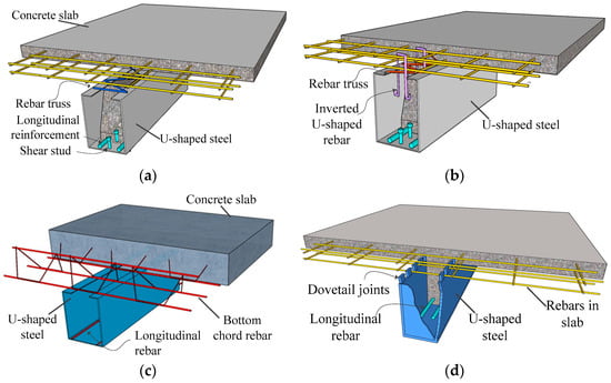
Figure 5.
Novel l shear connectors. (a) Weld rebar truss to varus flange; (b) rebar truss stiffened and inverted U-shaped rebar; (c) weld the bottom chord rebar to varus flange; (d) web-embedded shear connector.
In recent years, some researchers [23,36] proposed a similar treatment method using Perfobond rib connectors (Figure 6). Compared with varus or valgus flanges, straight-side U-shaped steel eliminates the need for a large number of welded shear studs or additional shear connectors. Making uniform perforations at the top of the U-shaped steel web to pass through the transverse reinforcement in the concrete slab enables composite action between the flange and the web. This approach overcomes the susceptibility of thin-walled steel plates to burn-through during welding and the practical difficulty of achieving 90° bending of the top flanges. Moreover, with approximately the same steel usage, it offers higher load-bearing capacity and initial stiffness.
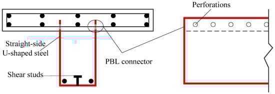
Figure 6.
Straight-side U-shaped steel-encased concrete composite beam.
To facilitate intuitive comparison and better serve engineering practice, the advantages and disadvantages of various traditional and novel shear connectors are summarized in Table 1. Furthermore, the primary classifications and specific construction details of USCCBs reported in the existing literature have been summarized in Table A1 in Appendix A.

Table 1.
Advantages and disadvantages of different types of shear connectors.
3.3. Influence of Shear Connection Strength
Previous studies [35,55,70,72] showed that if the shear connection strength at the weak surfaces is sufficient, the relative slip between the U-shaped steel and the concrete can be ignored at the ultimate limit state. In this case, the composite beam has a single neutral axis and undergoes typical flexural failure, which is known as a full shear connection. Conversely, if the shear connection strength at the weak interfaces is insufficient, longitudinal shear failure or vertical uplift failure may occur at the flange−web interface, while sliding failure may occur at the steel−concrete interface at the ultimate limit state. Under such conditions, the U-shaped steel and concrete cannot work well together, and the material properties cannot be fully utilized. Separate neutral axes develop in the steel and concrete components, and consequently, the flexural capacity was relatively low, which is termed partial shear connection.
It can be seen that the shear connection strength plays a decisive role in governing the failure mode and mechanical performance of USCCBs. As expected, the mechanical performance of USCCBs with full shear connection is markedly superior to that of USCCBs with partial shear connection. Nevertheless, to reduce construction complexity or control costs, a partial shear connection can also be adopted, provided that the required load-bearing capacity is satisfied. With reasonable design, such systems can also achieve high ductility [74]. Under a full shear connection, the flexural capacity of a cross-section can be evaluated based on the simplified plastic theory. In contrast, for partial shear connection, the determination of flexural resistance must explicitly account for the effects of sliding and shear capacity. In addition, for different types of shear connectors, researchers investigated the components contributing to the shear connection strength and the influencing factors and proposed reliable methods for calculating shear connection strength [71,75].
4. Seismic Performance of USCCB−Column Joints
Framework joints are subjected to the combined effects of axial force, bending moment, and shear force from columns, alongside shear force and bending moment from beams, resulting in highly complex stress states. Once joint failure occurs, the connected beams and columns may fail simultaneously, and post-failure repair is particularly difficult. Therefore, as the key force transfer component between beams and columns, joints must possess sufficient strength, stiffness, ductility, and energy-absorption capacity. To enable the application of USCCBs into frame structures to form structural systems, extensive research has been conducted on various types of beam−column joints over the past decade.
4.1. Joints Between USCCBs and RC Columns or H-Shaped Steel Columns
Kim et al. [65] tested the seismic performance of joints between USCCBs and RC columns and found that joint failure occurred at the beam-end support. Local compressive failure at the beam end could be prevented by increasing the thickness of the supporting steel plates or the edge distance of the bolts. Their study emphasized that the Z-shaped side plates and the U-shaped base plate must be connected via high-strength bolts to form a U-shaped steel, and that it is necessary to extend the length of the beam-end supports. Park et al. [76] proposed a joint system in which USCCBs were welded to the longitudinal reinforcement of the RC column using diagonal rebars and stirrups, followed by formwork installation and concrete casting. The research findings indicated that plastic hinges formed at the beam ends, with inter-story drift ratios exceeding 4%. The specimens demonstrated favorable energy-absorption capacity, exhibiting minimal shear slip and bond slip at joints. The seismic shear capacity exceeded the required shear demand. However, to prevent joint failure caused by concrete crushing, no axial force was applied at the top of the column, which differs from practical conditions and thus requires further investigation. Hwang et al. [77] proposed a type of joint for USCCBs and RC columns strengthened with externally encased angle steel. The research found that peak loads were reached at inter-story drift ratios of 2% to 3%. The specimens ultimately failed by tensile fracture following web buckling of the composite beams. The ultimate inter-story drift ratios were approximately 4% for interior column joints and 3% for exterior column joints. The seismic shear capacity of the joints is jointly provided by the U-shaped steel web, the infilled concrete, steel plate strips, and stirrups. It can reach 1.53 to 2.22 times the shear demand, thus preventing joint shear failure. Nevertheless, this study did not apply sufficiently large axial loads to the column, nor did it consider the influence of the axial load ratio, which limits its applicability to real structural conditions.
In addition, Lee et al. [78] optimized the design of joints between USCCBs to H-shaped columns. The critical limit states, such as weld fracture, local buckling, concrete crushing, and steel bar buckling, were successfully controlled. This design ensured that plastic hinges appeared at the top of the beam-end strengthening zone. Finally, failure occurred due to a low-cycle fatigue fracture at the U-shaped steel base plate. The fatigue cracking originated at the cold-formed corner of the U-shaped steel section, and the inter-story drift ratio exceeded 5%, which was much greater than the requirements specified in the AISC seismic design provisions [79].
4.2. Joints Between USCCBs and CFST Columns
Through bolt fastening or welding, USCCBs and square CFST columns can be connected to form framework joints. This achieves the combined application of the two structural components, allowing them to fully exert their respective mechanical performance. In recent years, various forms of USCCB−column joints have been proposed, and a series of studies have been carried out.
Gan et al. [80] tested the seismic performance of a novel through-type joint (also known as mortise-and-tenon joint) (Figure 7). The study revealed that the specimen damage was primarily characterized by out-of-plane deformation of the square steel tube and slight crushing of the concrete slab at its top surface. Final failure occurred due to the fracture of channel steel within the joint region. Due to a slip between the concrete and the channel steel within the joint region, the hysteretic curve exhibited a distinct pinching effect. However, the inter-story drift ratio at failure was as high as 5.9%, exceeding the requirements for frame design. The equivalent viscous damping coefficient also exceeded that of conventional RC beam−column joints. Subsequently, Xu et al. [81,82] and Gan et al. [83] independently carried out design optimizations for this through-type joint. Their studies found that the typical failure modes included the local buckling of U-shaped steel at the beam ends, crushing of the concrete slab, and fracture of channel steel within the joint region. Welding at the intersections of the two double-channel steels in the joint region was found to effectively restrict the inter-channel slip. Compared with the unwelded cases, both the load-bearing capacity and energy-absorption capacity were significantly improved, albeit at the expense of reduced deformation capacity. An increase in axial load ratio also helped to limit inter-channel slip and enhance the peak load of the specimens. Additionally, the seismic shear capacity of this connection joint calculated with reference to the ASCE design guidelines [84] was approximately 2.4 times its shear demand. However, since the construction of this connection joint is different from those considered in the ASCE design guidelines, further targeted investigations are required.
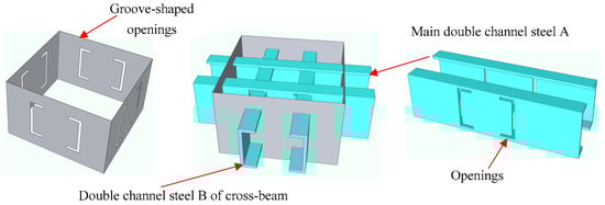
Figure 7.
A novel through-type joint (mortise-and-tenon joint).
In previous studies, the joints between square CFST columns and H-shaped steel beams are mainly classified into three types, namely, internal diaphragm, through diaphragm, and external diaphragm, based on the use of stiffeners [85,86,87]. Among these, the internal diaphragm type involves complex welding procedures and is unfavorable for concrete casting in the joint region. For the through diaphragm type, the diaphragm is typically required to protrude at least 25 mm beyond the steel tube to separate the heat-affected regions of adjacent welds, which will cause difficulties in component installation. For the external diaphragm type, the exposure of external diaphragms adversely affects the indoor usable space. In view of the structural characteristics of joints between USCCBs and square CFST columns, researchers proposed appropriate improvements to the above-mentioned three types of conventional joints. Lin et al. [88] proposed a part reinforcement-through with a diaphragm-through joint. The research found that the thickness of the concrete slab and the thickness of the U-shaped steel plate had significant impacts on the hysteretic behavior of the joints, while the longitudinal reinforcement ratio had a certain influence. Conversely, the thickness of the through diaphragm plate and the axial load ratio were found to have relatively small effects. Zhou et al. [89] refined the diaphragm-through joint by incorporating widened top flanges on the U-shaped steel near the joint region to prevent brittle failure. The research showed that the specimens failed due to tensile cracking at the weld joint of the U-shaped steel base plate and the diaphragm. The thickness of the U-shaped steel plate was identified as the most influential parameter governing the seismic performance, followed by the thickness of the diaphragm and the wall thickness of the steel tube. Xu and Cheng [90,91] studied the seismic performance of T-shaped internal diaphragm joints. The research revealed that the hysteretic characteristics of T-shaped internal diaphragm joints were comparable to those of traditional internal diaphragm joints. The introduction of H-shaped steel supports and stiffening plates at the connections was found to delay the fracture of the U-shaped steel base plate and enhance the ability of the joint to resist positive bending moments. Liu et al. [92] found that the ductility of the external diaphragm joints was superior to that of the internal diaphragm joints, while their seismic shear capacities were comparable. However, the internal diaphragm joints provided greater shear stiffness. Furthermore, specimens with well-compacted concrete in the joint core area exhibited flexural failure at the beam ends, whereas those with poorly compacted concrete in the joint core area experienced shear buckling failure of the steel tubes in the joint region. It is advisable to increase the thickness of the steel tube in the joint core area to enhance the ductility and energy-absorption capacity of the joints.
Overall, all the aforementioned types of joints, when properly designed, can satisfy the seismic deformation requirements. However, the mortise-and-tenon joints had a significant reduction in the shear stiffness of the joint region due to openings in the column wall. Under positive bending moments, the failure of various specimens usually manifested as tearing of the U-shaped steel along the welds in the cold-formed region at the lower part of the beam ends. It is therefore recommended that the cold-formed region of the U-shaped steel at the root of the composite beam be appropriately strengthened.
In addition to seismic performance, Jin et al. [93] conducted uniaxial static loading tests on the mortise-and-tenon joints. The research indicated that the shear capacity of the joints is contributed by three components, namely, the web of the double-channel steel, the web of the steel tube in the joint core area, and the diagonal concrete compression struts. Considering the reduction in the cross-sectional stiffness of the steel tube in the joint core area caused by the openings, it is recommended that compensatory rebars at the four inner corners of the column at the joints be provided. Zhang et al. [94] reported that the through-type joints satisfy the design requirements for concealed beams and columns, making them particularly suitable for beam−column joints with small cross sections in residential buildings. Heng et al. [95] found that under uniaxial static loading, joint failure was governed by buckling of the compressive flange of the column tube at the column end. Although the strong column and weak beam design principle was not achieved, the joints exhibited adequate stiffness and ductility. Based on the strut-and-tie model for concrete structures and the shear panel model for steel plates, a practical design method was proposed for this type of joint.
4.3. Joints Between USCCBs and Special-Shaped CFST Columns
The column limbs of special-shaped CFST columns are flush with the adjacent walls, which effectively eliminates protruding interior columns, increases usable indoor space, and meets the requirements of modern architectural design. In recent years, some researchers investigated the seismic performance of joints between USCCBs and special-shaped CFST columns. Xu et al. [96] applied through-type joints to T-shaped CFST columns and USCCBs. This type of joint was discussed in Section 4.2 (see Figure 7). The main technical procedure is summarized as follows. First, groove-shaped openings are cut at the corresponding positions on the three rectangular steel tubes, and the main double-channel steel A and round holes are drilled to allow the passage of reinforcing bars. The three rectangular steel tubes are then welded together to form a T-shaped composite steel tube column. Afterwards, the main double-channel steel A and double-channel steel B (of cross-beam) are inserted through the corresponding groove-shaped openings and welded to create a through-type joint. Finally, using the main double-channel steel A as the connecting piece, the U-shaped steel beam with an arc-cut end (to increase the length of the butt welds) is installed from bottom to top and connected to the main double-channel A by butt welding, with the connection end matching the arc-cut end. To ensure the effective transfer of internal forces, it is recommended that the thickness of the connecting double-channel steel be 1 to 2 mm greater than that of the U-shaped steel beam. Their research revealed that joint failure was characterized by the bulging of the steel tube at the joint, tearing of the connecting double-channel steel, and crushing of the concrete slab. These beam−column joints exhibited good ductility and energy-absorption capacity. Providing longitudinal reinforcement at the beam bottom passing through the panel zone or increasing the axial load ratio was found to enhance the bearing capacity and shear stiffness of the joint.
To address construction deficiencies associated with the external diaphragm and the adverse effects of the internal diaphragm on concrete casting, Cheng et al. [97] proposed a novel vertical stiffener joint between the T-shaped CFST columns and USCCBs. The T-shaped multi-cell CFST column is fabricated by welding a rectangular steel tube to two cold-formed U-shaped steel pieces, followed by concrete infilling. The USCCBs (varus flanges) are connected to the T-shaped CFST column using vertical stiffeners, with the width of the composite beam being equal to or close to that of the column limb. Specifically, the top and bottom flanges of the U-shaped steel are welded to the side plates of the column limbs through vertical stiffeners, and the negative moment reinforcement inside the composite beam is welded to the vertical stiffeners to transfer the beam-end moment. The U-shaped steel web is directly welded to the wall of the steel tube column to transfer the beam-end shear force. The research found that plastic hinges formed at the beam end at the junction between the vertical stiffener and the beam, while the bending deformation of the special-shaped CFST column and the shear deformation in the joint core region remained relatively small. The hysteretic curves exhibited a plump profile, demonstrating excellent energy-absorption capacity. Furthermore, to ensure that this type of joint satisfies rigid-joint requirements, it is suggested that the external height, internal height, thickness of the vertical stiffeners, and the connection length between the stiffeners and the composite beam flanges should not be less than 60%, 20%, 100%, and 150% of the width of the U-shaped steel beam, respectively.
Deng [98] proposed a type of joint between USCCBs and T-shaped CFST columns that employed side plate connections, which effectively overcomes the limitations associated with the narrow cavity that hinders the installation of internal diaphragms and the adverse effects of external diaphragms on the indoor architectural appearance. The construction of this joint is similar to that described in reference [97]. The primary difference lies in the fact that this joint is designed for USCCBs with valgus flanges. In this configuration, the side plate is only welded to the U-shaped steel web, the bottom flange (base plate), and the column limb, while the top flange of the U-shaped steel beam, at the end connected to the column, extends a certain distance to facilitate its connection with the column web. The results showed that, when properly designed, these joints with side plate connections failed through the formation of plastic hinges at the beam ends, accompanied by the buckling of the compression flange and tearing of the tension flange. To enhance the mechanical performance of the joint, it is recommended that the side plate height slightly exceeds that of the bottom flange of the U-shaped steel, provided that indoor space requirements are not compromised. This helps ensure that the welds in the joint region do not fall within the plastic deformation zone and the heat-affected zone. Furthermore, sufficient shear connectors should be installed at the joint region, and it is further recommended that the special-shaped steel tubes be fabricated as integral members.
In addition to the aforementioned beam−column joints, wall−beam joints in frame−shear wall structures also represent a potential weak link. Accordingly, some researchers studied the seismic performance of the joints between USCCBs and concrete-filled steel plate shear walls [99]. The research indicated that specimen failure was characterized by tensile tearing of U-shaped steel at the root of the USCCB, buckling of the U-shaped steel web, and fracturing of connections of the concrete flange slab and the steel plate shear wall. The load-bearing capacity and ductility of the structural components can be further enhanced by optimizing the connections between the slab reinforcement and the steel plate shear walls. Furthermore, some researchers conducted static loading tests on USCCB cross joints to investigate the mechanical performance of such beam-to-girder joints and the influencing factors [100,101].
5. RC Beams Strengthened with U-Shaped Steel Casings
The composite interaction between U-shaped steel casings and concrete beams significantly enhances the load-bearing capacity and ductility of the USCCBs, with the structural behavior analogous to that of FRP-reinforced RC beams. Inspired by this design concept, over the past decade, a number of researchers proposed strengthening techniques for beams strengthened with U-Shaped steel casings, achieving relatively satisfactory strengthening results.
Research by Lin et al. [102] revealed that when partially PC beams were strengthened using bonded U-shaped steel casings, the U-shaped steel effectively suppressed crack propagation, and the specimens exhibited typical flexural failure. Compared with unreinforced beams, the strengthened beams demonstrated a severalfold increase in flexural stiffness, yield load, and ultimate load. Additionally, initial damage had a certain influence on the yield load of the reinforced beams, but did not reduce their ultimate load capacity. Xu et al. [103,104] strengthened fire-damaged RC beams by externally applying thin-walled U-shaped steel plates and infilling non-shrinkage grouting material. This reinforcement technique effectively prevents debonding of the grouting material. By welding angle steel to the inner side of the U-shaped steel web and the top flange of the U-shaped steel to form an internal shear ring, a full shear connection between the strengthened components is achieved, thereby enabling effective composite action between the U-shaped steel casing and the concrete. The flexural failure of the reinforced beam is characterized by yielding of the thin-walled U-shaped steel base plate, yielding of the longitudinal reinforcement at the RC beam bottom, and crushing of the concrete in the compression zone. Notably, no slip was observed between the thin-walled U-shaped steel casing and the concrete during the failure process, nor was local buckling observed in the thin-walled U-shaped steel. Under shear loading, the strengthened beam exhibited pronounced local buckling of the thin-walled U-shaped steel web in the shear span, while the U-shaped steel base plate remained largely elastic, and crushing occurred in the upper compression zone of the concrete within the shear span. Compared with RC beams that were not fire-damaged, the flexural capacity and shear capacity of the strengthened beams could increase from 127.4% to 151.7% and 21.3 to 56.7%, respectively.
Generally, U-shaped steel strengthening techniques are classified into bonded strengthening, bolt anchoring, and composite anchoring based on the anchoring methods. Among them, bonded steel strengthening is prone to brittle debonding of the steel plates and long-term aging of the structural adhesive while bolt anchoring requires drilling holes that inevitably weaken the original beam cross-section and may reduce the strengthening efficiency due to the shear deformation of the bolts. In contrast, composite anchoring, where U-shaped steel casings are fixed to RC beams using high-strength bolts and structural adhesives with rebar adhesive injected into the bolt holes, can achieve better strengthening performance. In the context, researchers applied the U-shaped steel strengthening techniques (Figure 8a) to a practical engineering project [105], significantly enhancing the load-bearing capacity of frame beams, with minimal impact on the cross-sectional dimensions and external appearance of the components. After nearly two years of service, the reinforced beams exhibited no abnormal behaviors, demonstrating that the intended strengthening objectives were successfully achieved. Furthermore, a new method to strengthen RC beams with a U-shaped steel box was proposed (Figure 8b) [106], which could achieve rapid construction and great improvement in the flexural performance of RC beams. Compared with an unreinforced beam, the flexural capacity of the reinforced beams was enhanced from 5.2 to 7.6 times, while the secant stiffness was increased from 3.1 to 10.7 times. The test results showed that the failure started with yielding of the U-shaped steel base plate and ended with crushing of the concrete in the compression zone, accompanied by severe debonding and local buckling of the U-shaped steel web. Moreover, the initial loading level had little impact on the flexural performance of the reinforced beams. In contrast, as the thickness of the U-shaped steel base plate and the height of the steel box increased, the flexural performance of the reinforced beams significantly improved, with the effect of increasing the height of the steel box being more significant. Subsequently, the research team conducted constant-amplitude fatigue tests on strengthened beams [107], which demonstrated superior fatigue resistance of the U-shaped steel strengthening techniques for RC beams. The results indicated that fatigue failure of the strengthened beams was initiated with debonding and buckling of the U-shaped steel webs, followed by sudden rupture of the steel plates in the compression zone and crushing of the concrete. As the height of the steel box or the thickness of the base plate increased, the fatigue lives were substantially increased. It should be noted that in practical engineering applications, structural members are typically subjected to random variable-amplitude fatigue loads rather than constant-amplitude fatigue loads. Therefore, further investigations into the mechanical performance of the strengthened beams under a variable-amplitude fatigue load is necessary.
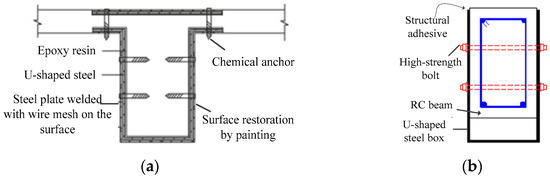
Figure 8.
RC beams strengthened with U-shaped steel casing. (a) Exterior-wrapping U-shaped steel plate [105]; (b) strengthened with U-shaped steel box.
In addition, Jin et al. [108,109] proposed a novel U-shaped steel and concrete composite strengthening technique that integrates the advantages of both bonded steel strengthening and steel plate−concrete composite strengthening. This technique has been successfully applied to the rehabilitation of over 50 prefabricated hollow core concrete slab bridges in China, achieving excellent strengthening outcomes. Subsequently, Jin et al. [110] conducted further experiments to analyze the flexural performance of RC beams with U-shaped steel and concrete composite strengthening. Testing results showed that the relative slip between the U-shaped steel and the concrete is minimal, enabling effective composite action between the strengthened system and the existing structure. Compared with un-strengthened beams, the cracking load of the strengthened beams increased by approximately 50%, while the ultimate load nearly doubled. Initial damage had a relatively small impact on the ultimate flexural capacity of the reinforced beams, but it significantly reduced the ductility. It is noteworthy that the longitudinal strengthening length of the steel plates has a significant impact on the sectional stiffness. Proper design of the strengthening length is therefore critical to prevent a shift in the failure mode from flexural failure to shear failure after strengthening. However, owing to the limited number of tested specimens, the effects of the thickness of U-shaped steel plates and bolt spacing require further investigation.
In summary, the U-shaped steel strengthening technology for RC beams is an emerging reinforcement technique, with strong effectiveness and broad application potential. This reinforcement technique was proposed and applied alongside the development of USCCBs. Essentially, the RC beam strengthened with a U-shaped steel casing can be regarded as a secondary composite USCCB. Techniques for extending the service life of USCCBs or enhancing their performance, as well as new technology USCCBs in the future, such as the anti-buckling design of U-shaped steel web, novel shear connectors, and beam−column joints, provide valuable guidance for the promotion and application of U-shaped steel strengthening technology for RC beams.
6. Research Gaps and Future Work
The literature review indicates that over the past decade or so, USCCBs have achieved substantial research advances in flexural, shear, torsional, and fire-resistance performance, and a variety of novel shear connectors have been successively proposed. In particular, significant research progress has been made in the seismic performance of beam−column joints and RC beams strengthened with U-shaped steel casings. Nevertheless, despite these developments, the research and practical application of USCCBs still face certain challenges and limitations, with notable gaps and deficiencies remaining in the existing body of knowledge. This section identifies the critical research gaps and outlines the principal future research directions, as shown in Figure 9.
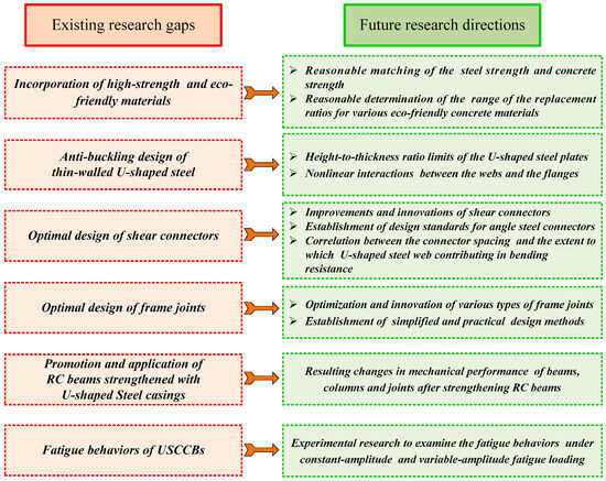
Figure 9.
Critical research gaps and future research directions.
6.1. Incorporation of High-Strength and Eco-Friendly Materials
Existing studies indicate that when U-shaped steel is fabricated from high-strength steel, the load-bearing capacity of the USCCBs can be significantly enhanced. However, their ductility is correspondingly reduced. Research on ensuring that USCCBs simultaneously achieve sufficient load-bearing capacity and satisfactory ductility remains limited. Future studies should therefore focus on the rational strength matching between high-strength steel and high-strength concrete. The incorporation of recycled concrete or other eco-friendly concrete materials into USCCBs by combining them with U-shaped steel offers significant environmental benefits. The replacement ratio of waste materials in recycled concrete is a critical parameter that influences the mechanical performance of the USCCBs, yet systematic investigations into its appropriate range are still lacking. It is thus necessary to further examine the effects of waste-material replacement ratios in eco-friendly concrete on the mechanical performance of USCCBs, and to determine a rational replacement range that enables their mechanical performance to be comparable to that of USCCBs cast with conventional concrete.
6.2. Anti-Buckling Design of Thin-Walled U-Shaped Steel
When subjected to relatively high compressive stresses, thin-walled U-shaped steel plates are prone to local buckling, which reduces the mechanical performance of the USCCBs. To prevent elastic buckling of the U-shaped steel plates from occurring prior to steel yielding, the height-to-thickness ratio limits of the U-shaped steel webs and the width-to-thickness ratio limits of the flanges should be properly designed. Existing studies on determining the height-to-thickness ratio of U-shaped steel webs are largely based on empirical statistics or by reference to relevant design codes, while theoretical investigations remain relatively limited. Therefore, further theoretical studies on the height-to-thickness ratio limits of U-shaped steel plates are warranted, and the nonlinear interactions between the webs and flanges should not be neglected.
6.3. Optimal Design of Shear Connectors
In existing studies, the design of angle steel connectors has largely been based on the provisions for channel steel connectors. No design codes provided explicit specifications for angle steel connectors, which may result in design inaccuracies, and this indicates the need for further systematic investigation and refinement. Further research should comprehensively consider both mechanical performance and construction efficiency to improve and innovate the shear connectors, with particular emphasis on the combined application of different types of shear connectors. Furthermore, the correlation between the connector spacing and the extent to which the U-shaped steel web contributes to bending resistance warrants further investigation.
6.4. Optimal Design of Frame Joints
Under strong seismic loading, beam−column joints often experience shear failure in the joint region rather than the intended formation of plastic hinges at the beam ends. At present, the failure mechanisms and mechanical performance of the joint core regions remain insufficiently understood. The joints between USCCBs and RC columns, steel columns, and CFST columns proposed in previous studies have relatively complex designs and vary significantly, and no systematic design methods have been established yet. Future research should focus on optimizing various types of joints and developing a simple and practical set of design guidelines to facilitate their implementation in practical engineering projects.
6.5. Promotion and Application of RC Beams Strengthened with U-Shaped Steel Casings
The U-shaped steel strengthening technique enables rapid and substantial enhancement of load-bearing capacity and stiffness of RC beams, with minimal changes to the member’s cross-sectional dimensions and relatively low self-weight, offering broad application prospects. Existing research predominantly focused on flexural and shear performance of strengthened beams, with relatively few studies examining the mechanical behaviors of joints after the strengthened beams are incorporated into frame structures. After RC beams are strengthened with U-shaped steel casings, it is likely to induce changes in the stiffness of the beams and columns, cause relocation of plastic hinges, and subsequently change the hysteretic behaviors of joints or reduce seismic shear capacity. Therefore, it is necessary to further reinforce beam−column joints after strengthening using U-shaped steel to form an integrated strengthened system and to conduct dedicated studies on this topic.
6.6. Fatigue Behaviors of USCCBs
To date, research on the fatigue behaviors of USCCBs remains very limited. When such components are employed in engineering structures, such as crane girders and highway or railway bridges that are subjected to long-term repetitive and cyclic dynamic loads, fatigue failure cannot be ignored. With the continuous increase in heavy loads and traffic volumes, fatigue-related issues in these structures have become increasingly prominent, making fatigue-resistant design indispensable.
7. Conclusions
This paper systematically reviews recent research achievements on USCCBs in the past decade or so. The review primarily covers the flexural performance of USCCBs, innovations and application of shear connectors, the seismic performance of beam−column joints, and the strengthening of RC beams using U-shaped steel casings. The current state of research on the shear, torsional, and fire-resistance performance of USCCBs is also summarized. Finally, the limitations and research gaps in existing studies are identified, and key directions for future research are outlined. Based on this literature review, it has been found that:
- (1)
- When U-shaped steel is fabricated from high-strength steel, an approximately matched concrete strength is required. Otherwise, the load-bearing capacity of the USCCB may increase significantly at the expense of insufficient ductility. When eco-friendly concrete is applied to USCCBs, it is crucial to determine a reasonable replacement ratio for recycled materials. This may enable their mechanical performance to be comparable to that of USCCBs cast with conventional concrete, thereby creating significant environmental and economic benefits.
- (2)
- Thin-walled U-shaped steel plates are prone to local buckling under high compressive stresses, which reduces the mechanical performance of the USCCBs. By fully considering the nonlinear interactions between the U-shaped steel web and flanges, and establishing rational limits for the height-to-thickness ratio (or width-to-thickness ratio), it is possible to effectively prevent premature buckling of thin-walled U-shaped steel plates and enhance the load-bearing capacity of USCCBs.
- (3)
- Shear connectors are pivotal for ensuring effective composite action between U-shaped steel and concrete. Under the condition of full shear connection, the composite beam has a single neutral axis and undergoes typical flexural failure. Under the condition of partial shear connection, separate neutral axes develop in the U-shaped steel and concrete components, and the material properties cannot be fully utilized, resulting in a relatively low flexural capacity. Accounting for the mechanical stability and the construction efficiency, existing shear connectors should therefore be improved and innovated, with particular emphasis on the combined use of different types of shear connectors.
- (4)
- At present, the failure mechanisms and mechanical performance of the joints between USCCBs and various types of frame columns remain insufficiently understood, and these joints are structurally complex and lack corresponding design standards. It is thus necessary to optimize and innovate these joints and to propose simplified and practical design methods.
- (5)
- The use of U-shaped steel to reinforce concrete beams shows great potential due to its excellent reinforcement effect and minimal impact on the self-weight and cross-sectional dimensions of the components. However, there is a lack of dedicated studies on the resulting changes in the mechanical performance of beams, columns, and joints after strengthening, which is not conducive to the widespread application of this technique.
- (6)
- Research on the fatigue performance of USCCBs remains relatively limited. The mechanical performance of USCCBs under constant-amplitude and variable-amplitude fatigue loading warrants further investigation.
Addressing the aforementioned issues in the existing studies will enable USCCBs to become lighter, stronger, and more environmentally sustainable. Such advancements will improve construction efficiency, facilitate full shear connection, prevent premature buckling of the thin-walled U-shaped steel plates, and allow the full exploitation of the mechanical properties of both materials. Furthermore, these developments will promote the wider application of USCCBs and RC beams strengthened with U-shaped steel casings in frame structures, ultimately forming integrated structural systems. In summary, the purpose of this review is to provide researchers with a comprehensive understanding of the current research status of USCCBs, to identify existing research gaps and future research priorities, and to further promote the development and practical application of USCCBs.
Author Contributions
Writing—original draft, Q.L.; conceptualization, Q.L. and F.Y.; investigation, Q.L. and F.Y.; writing—review and editing, Q.L.; methodology, Q.L.; visualization, W.H. and Q.L.; data curation, L.Z. and J.W.; funding acquisition, Q.L. and J.W. All authors have read and agreed to the published version of the manuscript.
Funding
This research was supported by the Key Research Project of Higher Education Institution in Henan Province (Grant No. 24A560025 and Grant No. 25A560002), and the International Science and Technology Cooperation Project of Henan Province (Grant No. 241111521200).
Data Availability Statement
The data that support the findings of this study are available from the corresponding author upon reasonable request.
Conflicts of Interest
Author Fangliang Yu was employed by the company Yellow River Engineering Consulting Co., Ltd. The remaining authors declare that the research was conducted in the absence of any commercial or financial relationships that could be construed as a potential conflict of interest.
Abbreviations
The following abbreviations are used in this manuscript:
| USCCBs | U-shaped steel−concrete composite beams |
| RC | Reinforced concrete |
| CFST | Concrete-filled steel tubular |
| PC | Prestressed concrete |
Appendix A
In order to provide a more comprehensive description of the main classifications and specific construction details of USCCBs in the existing literature, and to facilitate practical applications, the classification and typology of U-shaped composite beams are presented in Table A1, including different cross sections, shear connector types, the presence of stiffeners, etc.
Table A1.
Main classifications and specific construction details of USCCBs in the existing literature.
Table A1.
Main classifications and specific construction details of USCCBs in the existing literature.
| Cross Section | Shear Connector (FW) 1 | Shear Connector (SC) 2 | Stiffener | Forming Process | Reference |
|---|---|---|---|---|---|
| Varus Flange | Shear Studs | Shear Studs | / | Cold Forming & Welding | [5,10,11] |
| Shear Studs | / | No or Longitudinal Reinforcement | Cold Forming | [80,81,82,83,96,99] | |
| Shear Studs & Shear Reinforcement | Shear Studs | / | Cold Forming & Welding | [7] | |
| Shear Studs & Bottom Chord Rebar of Steel Truss Composite Deck | / | No or Longitudinal Reinforcement | Unknown | [72,93,94] | |
| / | Steel Rods | Stirrups & Longitudinal Reinforcement | Cold Forming | [9] | |
| / | No or Shear Studs | / | Cold Forming | [49] | |
| Rebar Truss | Shear Studs | Longitudinal Reinforcement | Cold Forming | [70] | |
| Rebar Truss & Inverted U-shaped Reinforcement | No or Shear Studs | Longitudinal Reinforcement | Cold Forming | [15,18,39,42,50,62,71,75,97,100] | |
| Channel Steel | / | / | Cold Forming | [19,20,54] | |
| Channel Steel | / | Longitudinal Reinforcement | Cold Forming | [61,62,90,91] | |
| Varus Flange & U-shaped Section with Lips | / | / | Longitudinal Reinforcement | Cold Forming & Welding | [6] |
| Shear Studs | / | / | Cold Forming & Welding | [76,78] | |
| Varus Flange & Profiled Sheet | Rebar Truss | / | Stirrups | Cold Forming | [2] |
| Valgus Flange | Square Bar; Angle Steel; Transverse Stirrups | / | Longitudinal Reinforcement | Unknown | [1] |
| Shear Studs | / | / | Cold Forming Or Cold Forming & Welding | [4,31,41,57,58,77] | |
| Shear Studs | / | Prestressed Longitudinal Reinforcement | Cold Forming | [31] | |
| Angle Steel | No or Shear studs | / | Welding | [16,35,66,67,68,92] | |
| / | Angle Steel | / | Welding | [67,68] | |
| Angle Steel | / | Longitudinal Reinforcement | Cold Forming | [33,34] | |
| Angle Steel & Transverse Stirrups | Shear Studs | Longitudinal Reinforcement | Unknown | [69] | |
| Angle Steel & Transverse Stirrups | / | Longitudinal Reinforcement | Cold Forming | [74,95] | |
| Shear Studs & Shear Reinforcement | Shear Studs | / | Cold Forming & Welding | [7,12,60] | |
| Shear Studs & Transverse Stirrups | Shear Studs | Longitudinal Reinforcement | Cold Forming & Welding | [8,26,27,28,29] | |
| Shear Studs & Transverse Stirrups | Angle Steel | No or Longitudinal Reinforcement | Welding | [59,98] | |
| Shear Studs | / | External Tendons | Unknown | [13] | |
| Shear Studs; Angle Steel | Shear Studs; Angle Steel | / | Welding | [48] | |
| Shear Studs; Angle Steel | Inner Diaphragm | / | Unknown | [14,50] | |
| Shear Studs | Inner Diaphragm | / | Unknown | [21] | |
| Shear Studs | Bolts or Shear Studs &Bolts | / | Bolt Fastening | [22,47] | |
| Shear Studs | Bolts | Longitudinal Reinforcement | Bolt Fastening | [30,65] | |
| Shear Reinforcement | / | / | Cold Forming | [64] | |
| / | Shear Studs | Prestressed & Conventional Longitudinal Reinforcement | Cold Forming | [32] | |
| / | Self-drilling Screws | / | Cold Forming & Self-drilling Screws | [43,55] | |
| / | Shear Studs & Inner Diaphragm | / | Unknown | [40] | |
| Valgus Flange & U-shaped Section with Lips | / | / | Longitudinal Reinforcement | Cold Forming & Welding | [6] |
| Shear Studs | Bolts | / | Bolt Fastening | [22] | |
| Shear Studs | Bolts | Longitudinal Reinforcement | Bolt Fastening | [30,65] | |
| Valgus Flange & Embossed Web | Angle Steel | / | / | Cold Forming & Welding | [37] |
| Dovetail-shaped Grooves at the Top of the U-shaped Steel Web | Web-embedded | No or Shear Studs | Longitudinal Reinforcement | Cold Forming & Laser cutting | [17,38,45,46,62,73] |
| Straight-side | Perfobond Rib Connector | Shear Studs | Longitudinal Reinforcement | Unknown | [23] |
| Transverse Stirrups | Shear Studs | Longitudinal Reinforcement | Cold Forming | [63] | |
| Varus Flange & Straight-side | Perfobond Rib Connector & Transverse Stirrups | Shear Studs | Longitudinal Reinforcement | Unknown | [24] |
| Straight-side & Corrugated Profiles (Base Plate) | Perfobond Rib Connector & Transverse Stirrups | Shear Studs | Longitudinal Reinforcement | Cold Forming & Welding | [36] |
1 FW denotes the flange−web interface. 2 SC denotes the steel−concrete interface.
References
- Keo, P.; Lepourry, C.; Somja, H.; Frank, P. Behavior of a New Shear Connector for U-Shaped Steel-Concrete Hybrid Beams. J. Constr. Steel Res. 2018, 145, 153–166. [Google Scholar] [CrossRef]
- Oehlers, D.J.; Wright, H.D.; Burnet, M.J. Flexural Strength of Profiled Beams. J. Struct. Eng. 1994, 120, 378–393. [Google Scholar] [CrossRef]
- Leskelä, M.V.; Inha, T.; Iso-Mustajärvi, P. A Concrete T-Section-Steel U-Section Composite Beam. In Proceedings of the Composite Construction in Steel and Concrete III (ASCE), Irsee, Germany, 9–14 June 1997; pp. 157–171. [Google Scholar]
- Nakamura, S.-I. Bending Behavior of Composite Girders with Cold Formed Steel U Section. J. Struct. Eng. 2002, 9, 1169–1176. [Google Scholar] [CrossRef]
- Xiao, H.; Li, A.Q.; Du, D.R. Experimental Study on Ultimate Flexural Capacity of Steel Encased Concrete Composite Beams. J. Southeast Univ. (Engl. Ed.) 2005, 21, 191–196. [Google Scholar]
- Zhang, Y.C.; Mao, X.Y.; Cao, B.Z. Experimental Study and Nonlinear Finite Element Analysis of Lightweight Steel-Concrete Composite Beams. J. Build. Struct. 2003, 24, 24–33. [Google Scholar] [CrossRef]
- Dong, K. Study on Design Method of the Steel Encased Concrete Composite Beams. Master’s Thesis, Ocean University of China, Qingdao, China, 2012. [Google Scholar]
- Wu, Z.Y.; Wang, R.P.; Luo, Y.F.; Li, W.X.; Huang, Q.L.; Ding, Y. Study on Flexural Behavior of Cold-Formed U-Shape Steel Encased Concrete Composite Beams. Struct. Eng. 2018, 34, 117–127. [Google Scholar]
- Hossain, K.M.A. Designing Thin-Walled Composite-Filled Beams. Proc. Inst. Civ. Eng. Struct. Build. 2005, 158, 267–278. [Google Scholar] [CrossRef]
- Chen, L.H.; Li, A.Q.; Lu, F.Y.; Lou, Y.; Li, P.B. Experimental study on joints of outer-plated steel-concretecomposite beam and reinforced concrete columns. China Civ. Eng. J. 2007, 40, 41–47. [Google Scholar] [CrossRef]
- Chen, L.H.; Li, A.Q.; Lu, F.Y.; Lou, Y.; Li, P.B. Experimental investigation on joints connecting outer-plated steel-concrete continuous composite beam and shaped-steel concrete column. J. Southeast Univ. (Natual Sci. Ed.) 2007, 37, 656–660. [Google Scholar]
- Shi, Q.Y.; Cai, J.L.; Chen, Q.Q.; Li, A.Q.; Qin, W.H. Torsional experimental and analysis on steel-encased concrete compostie beams. Eng. Mech. 2008, 25, 162–169. [Google Scholar]
- Zhang, N.; Fu, C.C. Experimental and theoretical studies on composite steel-concrete box beams with external tendons. Eng. Struct. 2009, 31, 275–283. [Google Scholar] [CrossRef]
- Zhou, X.J.; Zhang, T. Theoretical analysis of shearing capacity of U-section steel-encased concrete composite beams with the full connection design. Appl. Mech. Mater. 2011, 94, 958–961. [Google Scholar] [CrossRef]
- Guo, X. Research on Flexural Behavior of a Novel Cold-Formed U-Shaped Steel-Concrete Composite Beam. Master’s Thesis, Chongqing University, Chongqing, China, 2018. [Google Scholar]
- He, C. Study on Flexural Behavior of Composite Beams with U-Shaped Steel Section. Master’s Thesis, Harbin Institute of Technology, Harbin, China, 2014. [Google Scholar]
- Hu, S.W. Negative Bending Behavior of Web-Embedded U-Shaped Steel-Concrete Composite Beams. Master’s Thesis, Chongqing University, Chongqing, China, 2022. [Google Scholar]
- Zhao, Y.; Zhou, X.H.; Yang, Y.L.; Chen, Y.F.; Gurupackiam, S. Stiffness and Cracking Behavior of New U-Shaped Steel and Concrete Composite Beam under Negative Bending. J. Struct. Eng. 2020, 146, 04020046. [Google Scholar] [CrossRef]
- Wu, H.T. Analysis of Bearing Capacity and Crack Width in Negative Moment Zone of Externally Inverted U-Shaped Steel Concrete Composite Beams. Master’s Thesis, Chongqing Jiaotong University, Chongqing, China, 2024. [Google Scholar]
- Jiang, S.Y.; Wu, H.T.; Jiang, Z.K.; Zhao, Y.; Zhou, J.; Liu, X.G. Research on Bending Performance of Externally Inverted U-Shaped Steel Concrete Composite Beams in Negative Moment Zone. Struct. Eng. 2025, 41, 118–132. [Google Scholar]
- Lin, Y.; Zhou, X.J. Bearing capacity calculation of U-section steel-encased concrete composite beam. J. Shandong Jianzhu Univ. 2017, 32, 21–27. [Google Scholar]
- Kim, C.G.; Kim, H.S.; Lee, S.H. Experimental Investigation on Flexural Behavior of U-Shaped Steel-Concrete Composite Beams with Bolt Connections under a Negative Bending Moment. J. Struct. Eng. 2023, 149, 04023091. [Google Scholar] [CrossRef]
- Yan, Q.W.; Zhang, Z.; Yan, J.; Laflamme, S. Analysis of flexural capacity of a novel straight-side U-shaped steel-encased concrete composite beam. Eng. Struct. 2021, 242, 112447. [Google Scholar] [CrossRef]
- Yan, Q.W.; Zhang, Z. Analysis of normal section bending bearing capacity of inverted U-shaped Steel-encased concrete composite beam. J. Civ. Environ. Eng. 2020, 42, 81–94. [Google Scholar]
- Hu, B. Study on Mechanical Properties of the U Steel Encased Concrete Composite Beams. Master’s Thesis, Guangzhou University, Guangzhou, China, 2016. [Google Scholar]
- Cao, L.L.; Shi, Q.Y.; Wang, Z.; Ge, Y.T.; Li, A.Q. Bending Performance of High-Strength Steel-Encased Composite Beams. J. Southwest Jiaotong Univ. 2014, 49, 72–78. [Google Scholar] [CrossRef]
- Cao, L.L.; Li, Y.J.; Dhanasekar, M.; Lu, C.H. Experimental and Numerical Study on Flexural Performance of a Novel Steel-Encased Concrete Composite Beam. KSCE J. Civ. Eng. 2021, 25, 1837–1848. [Google Scholar] [CrossRef]
- Ren, G.Y.; Shi, Q.Y. Experimental study on flexural performance of high-strength steel-encased and high-strength concrete simply-supported composite beams. Build. Struct. 2015, 45, 39–43. [Google Scholar]
- Li, Y.J.; Shi, Q.Y.; Ren, G.Y.; Zhang, Z.C.; Li, Y.R.; Lu, F. Study on ductility of high-strength steel-encased composite beam. Build. Struct. 2017, 47, 94–99. [Google Scholar]
- Kim, S.B.; Cho, S.H.; Choi, Y.H.; Kim, S.S. An Experimental Study on Bending Performance of Hybrid Forming Composite Beam. Int. J. Steel Struct. 2017, 17, 1639–1649. [Google Scholar] [CrossRef]
- Yu, J.J. Theoretical Analysis and Experimental Research on Prestressed Composite Girders of Cold-Formed Steel U Sections and Concrete. Ph.D. Thesis, Northeastern University, Shenyang, China, 2015. [Google Scholar]
- Liu, J.P.; Chen, G.P.; Chen, Y.F.; Xu, T.X. Experimental study on the flexural behavior of cold-Formed U-shaped steel-encased confined prestressed RC beam. J. Constr. Steel Res. 2021, 182, 106656. [Google Scholar] [CrossRef]
- Wu, B.; Ji, M.M. Flexural tests on thin-walled U-shaped steel beams filled with demolished concrete blocks and fresh concrete. J. Build. Struct. 2014, 35, 246–254. [Google Scholar] [CrossRef]
- Ji, M.M. Study on Flexural and Fire Behaviors of U-Shaped Steel Beams Filled with Demolished Concrete Lumps and Fresh Concrete. Ph.D. Thesis, South China University of Technology, Guangzhou, China, 2018. [Google Scholar]
- Dang, X.Z. Study on Flexural Behavior of the Composite Beams with U-Shaped Steel Encased Recycled Concrete Section. Master’s Thesis, Chang’an University, Xi’an, China, 2018. [Google Scholar]
- Athira, V.; Prasad, R. Comparison of Structural Performance of U-Shaped Concrete Composite Beam having Steel Encasing with Corrugated Profiles. In SECON’22, Lecture Notes in Civil Engineering, Proceedings of the International Conference on Structural Engineering and Construction Management, Kerala, India, 7–9 June 2023; Spriger Nature: Berlin/Heidelberg, Germany, 2022; Volume 284, pp. 739–747. [Google Scholar] [CrossRef]
- Lee, J.S.; Haroon, M.; Kang, S.H.; Shin, K.J.; Lee, H.D. Flexural behavior of large-scale U-shaped steel-concrete infilled composite beams with flat and embossed webs. Structures 2023, 55, 1949–1959. [Google Scholar] [CrossRef]
- Yang, Y.L.; Sun, T.P.; Han, J.J. Study on Shear Behavior of Web-Embedded U-Shaped Steel-Concrete Composite Beam. Eng. Mech. 2022, 39, 120–136. [Google Scholar] [CrossRef]
- Zhao, Y.; Zhou, X.H.; Yang, Y.L.; Liu, J.P.; Chen, Y.F. Shear behavior of a novel cold-formed U-shaped steel and concrete composite beam. Eng. Struct. 2019, 200, 109745. [Google Scholar] [CrossRef]
- Ding, J.Y. Experimental Study on Shear Behavior of Composite Deep Beams with U-Shaped Steel and Concrete. Master’s Thesis, Changchun Institute of Technology, Changchun, China, 2022. [Google Scholar]
- Tian, F. Analysis of Mechanical Performance of U-Section Steel-Encased Concrete Composite Beams. Master’s Thesis, Harbin Engineering University, Harbin, China, 2014. [Google Scholar]
- Zhao, Y.; Zhou, X.H.; Yang, Y.L.; Liu, J.P.; Chen, Y.F. Torsional effects of a novel rebar stiffened cold-formed U-shaped steel-concrete composite beam system. Eng. Struct. 2020, 208, 109920. [Google Scholar] [CrossRef]
- Turetta, M.; Odenbreit, C.; Khelil, A.; Martin, P.-O. Investigations on the lateral-torsional buckling of an innovative U-shaped steel beam. Structures 2022, 44, 1328–1346. [Google Scholar] [CrossRef]
- EN1993-1-3; Eurocode 3: Design of Steel Structures, Part 1-3: General Rules—Supplementary Rules for Cold-Formed Members and Sheeting. European Committee for Standardization (CEN): Brussels, Belgium, 2007.
- Yang, Y.L.; Yang, Q.J.; Liu, Y.; Lu, G.Y.; Huang, X.D.; Chen, Y.F.; Yu, Y. Torsional performance of web-embedded U-shaped steel-concrete composite beams. Eng. Struct. 2025, 336, 120169. [Google Scholar] [CrossRef]
- Yang, Y.L.; Lu, G.Y.; Liu, Y.; Jiang, S.Y.; Chen, Y.F.; Yu, Y. Flexural-torsional performance of web-embedded U-shaped steel-concrete composite beams. Structures 2025, 75, 108744. [Google Scholar] [CrossRef]
- Kim, C.G.; Kim, H.S.; Lee, H.J. Flexural Capacity of Bolted U-Shaped Steel–Concrete Composite Beams under Monotonic and Cyclic Loading. J. Struct. Eng. 2023, 149, 04023168. [Google Scholar] [CrossRef]
- Eom, T.S.; Lim, J.J. Flexural Behavior of Noncompact and Slender Concrete-Filled U-Section Beams under Negative Bending. J. Struct. Eng. 2022, 148, 04022157. [Google Scholar] [CrossRef]
- Ipe, T.V.; Bai, S.H.; Vani, K.M.; Iqbal, M.M.Z. Flexural behavior of cold-formed steel concrete composite beams. Steel Compos. Struct. 2013, 14, 105–120. [Google Scholar] [CrossRef]
- Zhou, X.H.; Zhao, Y.; Liu, J.P.; Chen, Y.F.; Yang, Y.L. Bending experiment on a novel configuration of cold-formed U-shaped steel-concrete composite beams. Eng. Struct. 2019, 180, 124–133. [Google Scholar] [CrossRef]
- Zhou, X.J.; Lin, Y. Theoretical Research and Design Application of U-Section Steel-Encased Concrete Beam; Science Press: Beijing, China, 2016; pp. 210–218. [Google Scholar]
- GB50017-2003; Code for Design of Steel Structures. Ministry of Housing and Urban-Rural Development of the People’s Republic of China (MOHURD): Beijing, China, 2003.
- Shen, X. Study on Flexural Behavior of RC Beams Strengthened by U-Shaped Steel Plates as Box Structures. Ph.D. Thesis, Wuhan University, Wuhan, China, 2018. [Google Scholar]
- Cheng, R.; Yu, Y.L.; Zhang, J.Y.; Zhang, Q.F. Width-thickness ratio limit of outer steel plate of steel-concrete composite beam with U-section based on section classification. J. Civ. Environ. Eng. 2023, 47, 66–77. [Google Scholar]
- Turetta, M.; Odenbreit, C.; Khelil, A.; Martin, P.O. Investigation on the flexural behavior of an innovative U-shaped steel-concrete composite beam. Steel Compos. Struct. 2020, 34, 441–452. [Google Scholar] [CrossRef]
- GB/T 9978.1-2008; Fire-Resistance Tests—Elements of Building Construction—Part 1: General Requirements (ISO 834-1: 1999, MOD). Standardization Administration of the People’s Republic of China (SAC): Beijing, China, 2008.
- Gao, X.N.; Huang, W.H.; Zhu, H.M. Parametric Analysis of fire-resistant behavior of cold-formed thin-walled channel steel concrete beam. J. Build. Struct. 2012, 33, 133–140. [Google Scholar] [CrossRef]
- Gao, X.N.; Huang, W.H.; Zhu, H.M. Experimental research on cold-formed thin-walled channel steel concrete beam exposed to fire. J. Build. Struct. 2012, 33, 141–149. [Google Scholar] [CrossRef]
- Liu, Y. Flexural Behaviour and Fire Resistance of Composite Beams with U-Shaped Steel Girder and Angle Connectors. Ph.D. Thesis, Harbin Institute of Technology, Harbin, China, 2019. [Google Scholar]
- Gao, G.Y.; Dong, K.; Sun, K.J. Temperature Criterion-Based Fire Protection Design Method of U-Shaped Steel-Concrete Composite Beams. In Proceedings of the Technical Exchange Conference on Seismic Resistance of Engineering Structures, Kunming, China, 23–25 May 2024; Volume 1, pp. 186–193. [Google Scholar]
- Yang, W.Q.; Yang, Y.L.; Wang, G.J.; Liu, F.Q.; Chen, Y.F. Experimental research on fire performance of U-shaped steel-concrete composite beam under uniformly distributed loading. Thin-Walled Struct. 2023, 186, 110700. [Google Scholar] [CrossRef]
- Yang, W.Q.; Yang, Y.L.; Liu, F.Q.; Chen, Y.F. Fire experiment and fire design method of U-shaped steel-concrete composite beams. Adv. Struct. Eng. 2024, 27, 233–252. [Google Scholar] [CrossRef]
- Liu, Y.B. Steel-Concrete Cooperative Working Mechanism and Bearing Capacity Analysis of U-Shaped Semi Clad Composite Beam. Master’s Thesis, China University of Mining and Technology, Xuzhou, China, 2022. [Google Scholar]
- Li, W.H.; Zhao, F.H. Experimental Investigation and Nonlinear Finite Element Analysis of U-Shaped Steel-Concrete Composite Beam. Appl. Mech. Mater. 2012, 166, 477–481. [Google Scholar] [CrossRef]
- Kim, S.B.; Lee, E.T.; Kim, J.R.; Kim, S.S. Experimental Study on Bending Behavior and Seismic Performance of Hybrid Composite Beam with New Shape. Int. J. Steel Struct. 2016, 16, 477–488. [Google Scholar] [CrossRef]
- Ahn, T.S.; Kim, Y.J.; Dong, W.J.; Cha, S.R.; Kim, H.; Yong, C.J.; Jeon, G.S.; Dong, B.S.; Bae, J.H.; Jin, W.K. Steel Frame Structure Using U-Shaped Composite Beam. U.S. Patent US20130283721A1, 31 October 2013. [Google Scholar]
- Liu, Y.; Guo, L.H.; Qu, B.; Zhang, S.M. Experimental investigation on the flexural behavior of steel-concrete composite beams with U-shaped steel girders and angle connector. Eng. Struct. 2017, 131, 492–502. [Google Scholar] [CrossRef]
- Liu, Y.; Guo, L.H.; Shi, J.; Wang, J.F. Push-Out tests of shear connectors in U-shaped steel-concrete composite girder. Structures 2021, 31, 769–780. [Google Scholar] [CrossRef]
- Zeng, S. Semi-Precast U-Shaped Composite Beams Incorporating Recycled Lump Concrete Segments: Shear Behavior of Their Bolt-Connected Angle Connectors and Overall Flexural Response. Master’s Thesis, South China University of Technology, Guangzhou, China, 2024. [Google Scholar]
- Liu, J.P.; Zhao, Y.; Chen, Y.F.; Xu, S.Q.; Yang, Y.L. Flexural behavior of rebar truss stiffened cold-formed U-shaped steel-concrete composite beams. J. Constr. Steel Res. 2018, 150, 175–185. [Google Scholar] [CrossRef]
- Liu, J.P.; Zhao, Y.; Yang, Y.L.; Chen, Y.F. Bending Capacity and Elastic Stiffness for a Novel Configuration of Cold-Formed U-Shaped Steel-and-Concrete Composite Beams. J. Struct. Eng. 2019, 145, 04019106. [Google Scholar] [CrossRef]
- Xu, X.; Cheng, R.; Liu, J.C.; Cui, J.; Huang, Z.M. Flexural Behavior of U-Shaped Steel-Concrete Composite Beams with Steel-Bars Truss Deck in Different Shear Connectors. J. Hunan Univ. (Nat. Sci.) 2022, 49, 42–50. [Google Scholar] [CrossRef]
- Yang, Y.L.; Liu, Y.; Yang, Q.J.; Hu, S.W. Positive flexural behavior of web-embedded U-shaped steel-concrete beam. J. Build. Struct. 2023, 44, 166–181. [Google Scholar] [CrossRef]
- Lepourry-Nicollet, C.; Heng, P.; Somja, H.; Palas, F. Influence of partial shear connection on the behaviour of U-shaped steel concrete beams with L-shaped shear connectors. Eng. Struct. 2023, 278, 115360. [Google Scholar] [CrossRef]
- Zhao, Y.; Yang, Y.L.; Xu, S.Q.; Liu, J.P.; Chen, Y.F. Shear connection of reinforcement stiffened cold-formed U-shaped steel and concrete composite beam. Eng. Struct. 2020, 219, 110862. [Google Scholar] [CrossRef]
- Park, H.G.; Hwang, H.J.; Lee, C.H.; Park, C.H.; Lee, C.N. Cyclic loading test for concrete-filled U-shaped steel beam–RC column connections. Eng. Struct. 2012, 36, 325–336. [Google Scholar] [CrossRef]
- Hwang, H.J.; Eom, T.S.; Park, H.G.; Lee, S.H.; Kim, H.S. Cyclic Loading Test for Beam-Column Connections of Concrete-Filled U-Shaped Steel Beams and Concrete-Encased Steel Angle Columns. J. Struct. Eng. 2015, 141, 04015020. [Google Scholar] [CrossRef]
- Lee, C.H.; Park, H.G.; Park, C.H.; Hwang, H.J.; Lee, C.N.; Kim, H.S.; Kim, S.B. Cyclic Seismic Testing of Composite Concrete-Filled U-Shaped Steel Beam to H-Shaped Column Connections. J. Struct. Eng. 2013, 139, 360–378. [Google Scholar] [CrossRef]
- AISC 341-05; Seismic Provisions for Structural Steel Buildings. American Institute of Steel Construction (AISC): Chicago, IL, USA, 2005.
- Gan, D.; Feng, Y.; Cheng, R.; Zhou, X.H. Cyclic Tests of Concrete-Filled U-Shaped Steel Beam to Concrete-Filled Square Steel Tube Column Joints. In Proceedings of the Ninth International Conference on Advances in Steel Structures (ICASS), Hong Kong, China, 5–7 December 2018. [Google Scholar] [CrossRef]
- Xu, X.; Cheng, R.; Yang, P.; Liu, R.Q. Cyclic Loading Test for Concrete-Filled U-Shaped Steel Beam to Concrete-Filled Steel Tube Column Connections. Int. J. Steel Struct. 2020, 20, 1859–1870. [Google Scholar] [CrossRef]
- Xu, X.; Cheng, R.; Jiang, S.Y.; Yang, P.; Gan, D.; Cui, J. Experimental studies on seismic performance of square concrete-filled steel tubular column to U-shaped steel-concrete composite beam joints under cyclic loading. J. Build. Struct. 2021, 42, 83–90. [Google Scholar] [CrossRef]
- Gan, D.; Yan, F.; Yang, Z.Q.; Zhou, Z.; Cheng, R. Behavior of CFST Column to Concrete-Filled U-Shaped Steel Beam Joints with Slabs under Cyclic Loading. J. Struct. Eng. 2022, 148, 04021299. [Google Scholar] [CrossRef]
- ASCE Task Committee on Design Criteria for Composite Structures in Steel and Concrete. Guidelines for design of joints between steel beams and reinforced concrete columns. J. Struct. Eng. 1994, 120, 2330–2357. [Google Scholar] [CrossRef]
- Qin, Y.; Chen, Z.H.; Wang, X.D. Experimental investigation of new internal-diaphragm connections to CFT columns under cyclic loading. J. Constr. Steel Res. 2014, 98, 35–44. [Google Scholar] [CrossRef]
- Vulcu, C.; Stratan, A.; Ciutina, A.; Dubina, D. Beam-to-CFT High-Strength Joints with External Diaphragm. I: Design and Experimental Validation. J. Struct. Eng. 2017, 143, 04017001. [Google Scholar] [CrossRef]
- Yu, Y.J.; Nie, X.Z.; Zhang, C.; Ding, F.X.; Guo, W. Seismic behavior of bottom-flange-bolted type through-diaphragm connection considering the slab effect. Eng. Struct. 2021, 229, 111642. [Google Scholar] [CrossRef]
- Lin, Y.; Zhou, X.J.; Jiang, W.; Yao, Z.J. Analysis on hysteretic behavior of concrete-filled square steel tubular column to steel-encased concrete composite beam connections. China Civ. Eng. J. 2015, 48, 72–81. [Google Scholar] [CrossRef]
- Zhou, J.; Yang, F. Experimental on a diaphragm connection between U-shaped steel concrete composite beams and square steel tube concrete columns. J. Shanghai Univ. (Nat. Sci. Ed.) 2021, 27, 1128–1137. [Google Scholar]
- Xu, X.; Cheng, R.; Yang, P.; Zhang, J.D.; Liu, J.C. Experimental Study of U-Shaped Steel-Concrete Composite Beam to Square CFST Column Joints. J. Constr. Steel Res. 2022, 192, 107220. [Google Scholar] [CrossRef]
- Xu, X.; Cheng, R.; Yang, P.; Yu, Y.L. Experimental and numerical investigations on square CFST column to U-shaped steel-concrete composite beam joints with internal T-shaped diaphragms. J. Build. Eng. 2022, 60, 105172. [Google Scholar] [CrossRef]
- Liu, Y.; Guo, L.H.; Zhang, S.M. Cyclic loading tests of composite joints between concrete-filled square steel tubular column and composite beam with U-shaped steel girder. J. Build. Struct. 2018, 39, 131–140. [Google Scholar] [CrossRef]
- Jin, B.; Luo, B.L.; Shu, X.P.; He, R. Experimental study and theoretical analysis on mechanical properties of mortise-tenon joints in composite frames. J. Build. Struct. 2022, 43, 173–183. [Google Scholar] [CrossRef]
- Zhang, Z.H.; Mao, G.X.; He, R.; Xiao, A.L.; Liu, Z.L. Bearing Capacity of Composite Joints of U-shaped Steel Composite Beams and Concrete-filled Square Steel Tubular Columns Based on Channel Steel Connectio. J. Eng. Sci. Technol. Rev. 2021, 14, 40–52. [Google Scholar] [CrossRef]
- Heng, P.; Lepourry, C.; Somja, H.; Palas, F. Behaviour of a joint between a U-shaped steel-concrete beam and a concrete-filled steel tubular column. J. Constr. Steel Res. 2020, 175, 106322. [Google Scholar] [CrossRef]
- Xu, X.; Cheng, R.; Yang, P.; Gan, D.; Liu, R.Q.; Hu, C. Seismic performance of special-shaped concrete-filled steel tubular column to U-shaped concrete-filled steel beam joints under cyclic loading. J. Build. Struct. 2020, 41, 136–144. [Google Scholar] [CrossRef]
- Cheng, Y.; Yang, Y.L.; Liu, J.P.; Zhou, Q.P. Seismic behavior of T-shaped multi-cell CFST column to U-shaped steel-concrete composite beam joint. J. Build. Struct. 2023, 44, 94–106. [Google Scholar] [CrossRef]
- Deng, L.M. Seismic Performance of T-Shaped CFST Column to U-Shaped Steel-Concrete Composite Beam Joints. Master’s Thesis, Harbin Institute of Technology, Harbin, China, 2022. [Google Scholar]
- Yang, P.; Luo, J.; Cheng, R.; Yu, Y.H.; Xu, X. Experimental study on seismic performance of connection between U-shaped concrete-filled steel beam and concrete-filled steel plate shear wall. J. Build. Struct. 2021, 42, 109–116. [Google Scholar] [CrossRef]
- Hu, Z.Q.; He, R.; Wang, Y.K.; Lv, W.R.; Li, J.C. Experimental Study on Mechanical Performance of U-Shaped Steel-Encased Concrete Composite Beam-Girder Joints. Adv. Civ. Eng. 2021, 2021, 5580292. [Google Scholar] [CrossRef]
- Liu, C.; Sun, Y.K.; Yu, S.B.; Li, S.; Wang, P.J.; Chen, B.; Xing, D.J. Flexural study on U-shaped steel–concrete composite beam cross joints with L-shaped connection longitudinal transition components. Structures 2023, 58, 105464. [Google Scholar] [CrossRef]
- Lin, Y.D.; Xia, Z.H.; Huang, D.D.; Zong, Z.H. Experimental Study on Flexural Properties of Prestressed Concrete Beams Strengthened with U-shaped Steel Plates. J. China Railw. Soc. 2012, 34, 94–102. [Google Scholar] [CrossRef]
- Xu, Y.Y.; Zheng, S.Y.; Dong, Y.L.; Luo, Y. Mechanical performance of reinforced concrete beams after fire and strengthened with thin-walled U-shaped steel plate. J. Build. Struct. 2017, 38, 58–66. [Google Scholar] [CrossRef]
- Xu, Y.Y.; Zheng, S.Y.; Dong, Y.L.; Luo, Y. Numerical Simulation of Thin-Walled U-Shaped Steel Strengthened Fire Damaged Reinforced Concrete Beams. J. Basic Sci. Eng. 2020, 28, 366–375. [Google Scholar] [CrossRef]
- Zhou, C.L.; Sun, J.K.; Zeng, Z.R.; Liu, J. Studies on the RC Beam Strengthened by Using the Exterior-Wrapping U-Shaped Steel Plate and Its Application. Adv. Civ. Eng. 2019, 2019, 2396764. [Google Scholar] [CrossRef]
- Lin, Q.L.; Lu, Y.Y.; Tang, W.S.; Lei, D.S. Experimental study on flexural strengthening of reinforced concrete beams with U-shaped steel under secondary load. Adv. Struct. Eng. 2021, 24, 3759–3777. [Google Scholar] [CrossRef]
- Lin, Q.L.; Lu, Y.Y.; Hu, L.; Zhao, X.B. Experimental and Numerical Study on Fatigue Behavior of RC Beams Strengthened with U-Shaped Steel Casing. Int. J. Steel Struct. 2022, 22, 514–538. [Google Scholar] [CrossRef]
- Jin, H.; Xu, Y.; Zheng, Q.C.; Shao, G.T. Application of Shaped Steel and Concrete Composite Reinforcement Technique to Hollow Slab Bridge. Bridge Constr. 2017, 47, 114–118. [Google Scholar]
- Jin, H.; Jiang, H.W.; Jiang, R.N.; Zhan, H.Y.; Xu, Y. Strengthening Hollow Core Concrete Bridges with Deficient Transverse Hinge Joints with a Steel and Concrete Composite Anchorage System. Transp. Res. Rec. 2020, 2674, 68–78. [Google Scholar] [CrossRef]
- Jin, H.; Xu, Y.; Jiang, F.H.; Cheng, J.X. Bending Behavior Experiment of RC Beams with U-Shaped Steel and Concrete Composite Reinforcement. China J. Highw. Transp. 2020, 33, 206–214. [Google Scholar]


Disclaimer/Publisher’s Note: The statements, opinions and data contained in all publications are solely those of the individual author(s) and contributor(s) and not of MDPI and/or the editor(s). MDPI and/or the editor(s) disclaim responsibility for any injury to people or property resulting from any ideas, methods, instructions or products referred to in the content. |
© 2026 by the authors. Licensee MDPI, Basel, Switzerland. This article is an open access article distributed under the terms and conditions of the Creative Commons Attribution (CC BY) license.