Abstract
For ground with trapezoidal distributed subgrade reaction coefficients caused by natural sedimentation, a calculation model for pile(wall) deflection deformation under lateral loads was established. Based on the theory of power series solution of differential equations, a power series solution for pile(wall) deflection deformation that considers the trapezoidal distribution of lateral loads and subgrade reaction coefficients was proposed. The power series solution can be degraded into the traditional K-method and m-method formulas for calculating pile(wall) deflection deformation. The results show that when the number of calculation terms of the power series solution is taken as 20, the maximum relative truncation error of the horizontal displacement is 0.19%, and the calculation accuracy can meet the requirements of theoretical analysis and engineering calculation. For long pile(wall) with a converted depth greater than 5 m, it is suggested to calculate at 5 m. The analysis of engineering examples demonstrates the validity. The proposed power series calculation method solves the problem of pile(wall) deflection deformation with trapezoidal distributed subgrade reaction coefficients under lateral loads, which the traditional K-method and m-method cannot solve. Compared with the finite element method, the computational efficiency of the deterministic method is improved. Therefore, the proposed method can support the establishment of calculation methods for complex problems such as pile(wall) deflection deformation in multi-layered ground and anti-slide piles under local lateral loads.
1. Introduction
In the design and calculation of railways, bridges and underground projects, the calculation method of pile(wall) deflection deformation is related to the distribution form of the subgrade reaction coefficients [1,2,3]. Usually, methods such as the K-method of rectangular distributed subgrade reaction coefficients with depth and the m-method of triangular distributed subgrade reaction coefficients with depth are adopted [4], among which the m-method is the main one. In 1964, Hu [5] proposed a calculation method for the deep-buried elastic foundations of bridge piers and abutments based on the m-method. In 1974, in order to promote and apply the m-method in engineering design, the Bridge and Tunnel Group of the Design Team of Wuhan Railway Bureau [6] proposed a simplified calculation method for high and low pile foundations applicable to vertical piles based on the basic principles of the m-method; the corresponding calculation coefficients table was compiled, thus the computational efficiency and engineering practicality of the m-method were enhanced. In 1976, based on the m-method and considering different support conditions, Fan [7] provided a static calculation method for underground wall(column) deflection deformation under full-height rectangular and triangular lateral loads. The m-method was then extended and applied to the calculation of underground engineering structures. Later, many scholars discussed the application of the m-method [8,9]. As a simplified calculation method for the deflection deformation of pile(wall), the m-method is still widely used in structural design, and it is often used as a benchmark for verifying complex numerical models. In recent years, most of the research on the m-method focuses on correcting the subgrade reaction coefficients through advanced testing techniques [10,11,12,13], or exploring its applicability in complex strata and special working conditions [14,15,16,17].
The m-method is a calculation method for pile(wall) deflection deformation based on the simplified assumption of subgrade reaction coefficients. Its advantages are that the calculation process is simple and the engineering practicality is good. However, the limitation of the m-method lies in the assumption that the subgrade reaction coefficient at the ground level is zero, as shown in Figure 1a, which cannot fully reflect the trapezoidal distribution pattern of the subgrade reaction coefficients when there is a burial depth at the top of the pile(wall) or the pile(wall) is in cohesive soil. The traditional m-method can only calculate the deflection deformation and action effect of pile(wall) under triangular, rectangular loads distributed along the full height of the pile(wall), and is unable to solve problems under lateral local loads. In order to solve the problem of pile(wall) deflection deformation with non-zero subgrade reaction coefficient at the ground level, Wang [18] proposed the equivalent transformation calculation model. The calculation coefficients of the m-method were utilized, and the calculation coefficient table that was related to the equivalent transformation was added. Zhan [19] proposed the coordinate translation calculation method for converting the burial depth of the pile top, as shown in Figure 1b, and recompiled a table of 16 calculation coefficients that were independent of the calculation coefficients of the m-method. Both of these methods utilize the m-method to calculate the trapezoidal distributed subgrade reaction coefficients, but they are only applicable in the absence of lateral loads. They are unable to solve the problem of pile(wall) deflection deformation under complex lateral loads in engineering practice. Thus, the application of the m-method in projects such as anti-slide piles [20,21] and foundation pit support piles [22,23] are restricted, and it also cannot be extended to the calculation of pile(wall) deflection deformation in multi-layered ground.
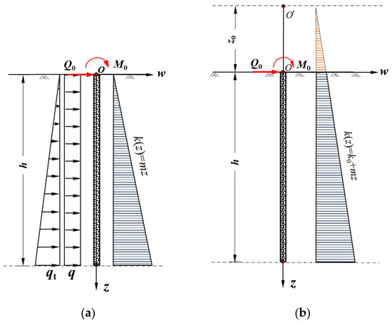
Figure 1.
Calculation models for pile(wall) deflection deformation: (a) The m-method and (b) the coordinate translation calculation method in reference [19].
The current m-method cannot solve the problem of pile(wall) deflection deformation considering the trapezoidal distribution of lateral loads and subgrade reaction coefficients. In response to the above issues, a calculation model of pile(wall) deflection deformation is established, which considers the trapezoidal distribution characteristic of the subgrade reaction coefficients varying with depth. Based on the power series solution theory of ordinary differential equations, the power series solution of pile(wall) deflection deformation, considering trapezoidal distributed lateral loads and subgrade reaction coefficients, is provided. The accuracy, convergence, and universality of this method have been verified. The concept of this method is clear, the calculation is simple, and the engineering applicability is good. It can be extended to the deflection deformation calculation of pile(wall) in multi-layered ground or in complex engineering conditions with local loads.
2. Static Calculation Method of Pile(Wall) Under Lateral Loads
2.1. Differential Equation of Pile(Wall) Deflection Deformation
To describe the mechanical characteristics of pile(wall) under lateral loads, a trapezoidal distributed subgrade reaction coefficients calculation model is established, as shown in Figure 2a.
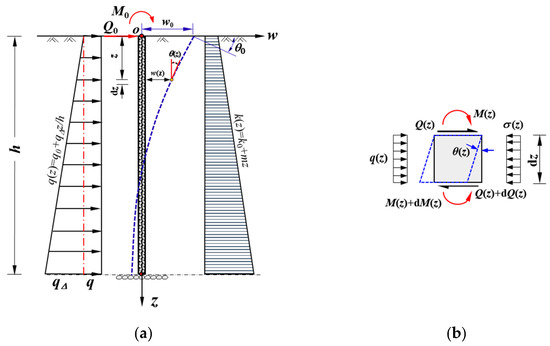
Figure 2.
Pile(wall) deflection deformation calculation model: (a) Trapezoidal distributed lateral loads and subgrade reaction coefficients; (b) Element body for mechanical analysis.
The basic assumptions are as follows:
- Elasticity assumption. The pile(wall) works within the elastic stage, and the stress is directly proportional to the strain;
- Planar section assumption. The pile(wall) cross-section, which is originally planar, remains planar after deformation;
- Small deformation assumption. Under the influence of external forces, the elastic deformation of pile(wall) is very small compared to its original size and can be neglected. Thus, the force balance, internal force, and deformation calculation problems of pile(wall) can be studied based on its original dimensions.
The symbols in the model are defined as: The origin of the z-axis coordinate is located at the ground level, and the downward direction is positive. The horizontal displacement w(z) is positive in the right direction. The rotation angle θ(z) is positive in the counterclockwise direction. The bending moment M(z) is positive when the left fiber is under tension. The shear force Q(z) is positive in the clockwise direction. The lateral load q(z) is positive in the right direction. The resistance of the soil σ(z) is positive in the left direction.
The trapezoidal distributed subgrade reaction coefficients k(z)
where k0 is the subgrade reaction coefficient at ground level, m is the proportional coefficient of the subgrade reaction coefficients, and z is the depth.
k(z) = k0 + mz
At depth z, take the element body with a thickness of dz. According to the equilibrium conditions and the principles of material mechanics, the differential equation of the pile(wall) deflection deformation can be obtained as
where EI is the bending stiffness and h is the underground length of the pile(wall), w(z) is the horizontal displacement of the pile(wall), b0 is the effective calculated width of the pile(wall) and the value as specified in Reference [4], q is the lateral uniformly distributed load, and qt is the lateral triangular distributed load.
For the boundary conditions at the top of the pile(wall), w0 is the horizontal displacement, θ0 is the rotation angle, M0 is the bending moment, and Q0 is the horizontal force.
Due to the trapezoidal distribution effects of the subgrade reaction coefficients and the lateral loads, the differential equation for the pile(wall) deflection deformation is a fourth-order linear variable coefficient non-homogeneous differential equation.
When m = 0, the value of k(z) does not change with depth z, and the subgrade reaction coefficients show a rectangular distribution (K-method). Equation (2) is transformed into a fourth-order constant-coefficient non-homogeneous differential equation, from which the exact analytical solution of the pile(wall) horizontal displacement w(z) can be derived.
When k0 = 0, the subgrade reaction coefficients show a triangular distribution (m-method). Equation (2) is transformed into a fourth-order linear variable coefficient non-homogeneous differential equation. An approximate solution can be obtained by using the power series method.
When m ≠ 0 and k0 ≠ 0, the subgrade reaction coefficients show a trapezoidal distribution. Equation (2) is a fourth-order linear variable coefficient non-homogeneous differential equation, which increases the difficulty of solving.
Let , , and Equation (2) transform into
The solution of Equation (3) consists of two parts, the general solution of the homogeneous equation with variable coefficient for pile(wall) without lateral loads, and the particular solution of the non-homogeneous equation with variable coefficient for pile(wall) under lateral loads. The calculation models of the general solution and particular solution are shown in Figure 3.
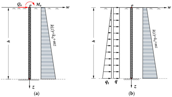
Figure 3.
Calculation models of the pile(wall) deflection deformation with trapezoidal distributed subgrade reaction coefficients: (a) general solution model without lateral load; and (b) particular solution model under lateral load.
2.2. Power Series Solution for Static Calculation of Pile(Wall) Deflection Deformation
The solution process of Equation (2) refers to the m-method power series solution [7]. Compared with the solution process of the m-method, Equation (2) simultaneously includes the variable coefficient term α5z and the constant term β4. For the calculation model given in Figure 3a, the differential equation of pile(wall) deflection deformation is a fourth-order linear variable coefficients homogeneous equation. According to the theory of solving ordinary differential equations by power series, the first 25 terms of the general solution wg(z) are:
As shown in Equation (4), the pile(wall) deflection deformation general solution of the power series is related to the horizontal displacement w0, the rotation angle θ0, the horizontal force Q0, and the bending moment M0 at the top of the pile(wall).
For the calculation model given in Figure 3b, the differential equation of pile(wall) deflection deformation is a fourth-order linear variable coefficients non-homogeneous equation. The first 25 terms of the particular solution wp(z) are:
As shown Equation (5), the pile(wall) deflection deformation particular solution of the power series is related to the lateral, uniformly distributed load q and the lateral, triangular distributed load qt acting on the side of the pile(wall).
Whether it is a general solution or a particular solution, its solution consists of three parts, which are related to the parameters α, β, and αβ. Among them, the terms containing parameter α are related to the triangular distributed subgrade reaction coefficients (m-method), and the terms containing parameter β are related to the rectangular distributed subgrade reaction coefficients (K-method). It is worth noting that the power series solution also includes terms related to the parameter αβ. It reflects the coupling effect between the linearly distributed subgrade reaction coefficient mz and the uniformly distributed subgrade reaction coefficient k0, and it leads to the nonlinear superposition of the distribution pattern of the subgrade resistance. It indicates that under the trapezoidal distribution of the subgrade reaction coefficients condition, the solution of the pile(wall) deflection deformation is not a simple superposition of the m-method solution and the K-method solution. It reflects the complexity of the problem of pile(wall) deflection deformation with trapezoidal distributed subgrade reaction coefficients. In addition, the trapezoidal distributed lateral loads further contribute to the complexity of the power series solution.
By adding Equations (4) and (5), the general power series solution of the pile(wall) horizontal displacement w(z) with trapezoidal distributed subgrade reaction coefficients under lateral loads is obtained:
Based on the horizontal displacement w(z), the rotation angle θ(z), the bending moment M(z), and the shear force Q(z) can be further calculated. The corresponding calculation formulas are as follows:
In Equations (6)–(9), Awz~AQz, Bwz~BQz, Cwz~CQz, Dwz~DQz, Ewz~EQz, and Fwz~FQz are the calculation coefficients. The corresponding calculation formulas are shown in Appendix A.
Equations (6)–(9) are the general power series solutions of pile(wall) deflection deformation without considering the support conditions at the top and bottom of the pile(wall). After introducing the support conditions, the particular power series solutions of pile(wall) deflection deformation can be obtained.
2.3. Static Calculation Methods of Pile(Wall) Deflection Deformation Under Different Support Conditions
The typical support conditions at both ends of the pile(wall) include free support, hinge support, and fixed support, which are shown in Table 1. Different combinations of support conditions at both ends directly affect the deflection deformation and the internal forces distribution of the pile(wall).

Table 1.
Typical support conditions at both ends of the pile(wall).
For the support conditions at pile(wall) top, there are four parameters: horizontal displacement w0, rotation angle θ0, horizontal load Q0, and bending moment M0. Among them, two values are known, and the other two values are unknown. The support conditions at pile(wall) bottom are similar. Among the four parameters of horizontal displacement wh, rotation angle θh, horizontal load Qh, and bending moment Mh, two values are known, and the other two values are unknown. Therefore, two equations can be established by using the support conditions at pile(wall) bottom. Then, by solving the linear equations in two variables, two unknown values at pile(wall) top can be determined. Thus, Equations (6)–(9) can be utilized to solve the deflection deformation and internal forces of the pile(wall).
Based on the support conditions at both ends of the pile(wall), the steps for determining the unknown value, calculating deflection deformation and internal forces of the pile(wall) are as follows:
- Substituting the two known values at pile(wall) top support conditions into Equations (6)–(9), four equations containing two unknown values can be obtained;
- Among the four equations obtained for the support conditions at pile(wall) top, select two equations of the same type as the known values for the support conditions at pile(wall) bottom, and solve the two unknown values at pile(wall) top;
- Substituting w0, θ0, Q0, and M0 (two known and two solved) into Equations (6)–(9), the deflection deformation and internal forces at any section of the pile(wall) under the corresponding support conditions can be solved.
Taking the conditions of free support at both ends of the pile(wall) as examples, the calculation model is shown in Figure 4. These boundary conditions are the most common situation in engineering practice. Free support conditions at pile(wall) top: z = 0, M0, and Q0 are known values, w0 and θ0 are unknown values. Free support conditions at pile(wall) bottom: z = h, Mh = 0, and Qh = 0.
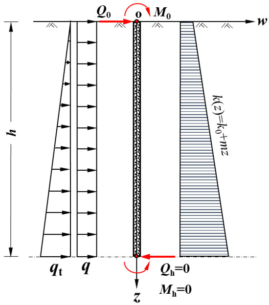
Figure 4.
Calculation model of free support conditions at both ends of the pile(wall).
Based on the power series solution for static calculation of pile(wall) deflection deformation, from Equations (8) and (9) and the free support conditions at pile(wall) bottom (Mh = 0, Qh = 0), a system of linear equations with two variables including the unknowns w0 and θ0 can be obtained:
Solving the Equation (10) yields:
where
On the basis of determining w0 and θ0, combining the pile(wall) top loads of M0 and Q0 and the lateral loads of q and qt, the horizontal displacement w(z), the rotation angle θ(z), the bending moment M(z), and the shear force Q(z) at any section of the pile(wall) can be calculated by solving Equations (6)–(9). The calculation formulas for the unknowns of pile(wall) under different support conditions are shown in Appendix B.
3. Verification of Power Series Solutions
3.1. Degradation Verification
The coefficients Awz, Bwz, Cwz, and Dwz of Equation (4) are related to the parameters α, β, and αβ. When α = 0, the subgrade reaction coefficients show a rectangular distribution (K-method). The coefficients Awz, Bwz, Cwz, and Dwz of Equation (4) degenerate into:
When β = 0, the subgrade reaction coefficients show a triangular distribution (m-method). The coefficients Awz, Bwz, Cwz, and Dwz of Equation (4) degenerate into:
By comparison, it can be known that when the trapezoidal distributed subgrade reaction coefficients degenerate into rectangular distributed subgrade reaction coefficients (α = 0), the coefficients of the power series solution of the pile(wall) in Equations (12)–(15) are the same as those of the K-method in reference [7]. When it degenerates into the triangular distributed subgrade reaction coefficients (β = 0), the coefficients of the displacement power series solution of the pile(wall) in Equations (16)–(19) are the same as those of the m-method in reference [7]. This indicates that the power series calculation method of pile(wall) deflection deformation based on trapezoidal distributed subgrade reaction coefficients has developed the traditional K-method and m-method. The lateral load factors are taken into account and the engineering applicability is enhanced. Therefore, the proposed power series calculation method can support the establishment of calculation methods for complex problems such as pile(wall) deflection deformation in multi-layered ground and anti-slide piles under local lateral loads.
3.2. Comparison and Verification of Finite Element Solutions
The diaphragm wall is shown in Figure 5. The depth is h = 20 m, the thickness is D = 1.2 m, the calculated width is b0 = 1.0 m, the elastic modulus is Ep = 2.7 × 10⁷ kPa, and the bending stiffness is EI = 0.8 EpI. The proportional coefficient of the subgrade reaction coefficients is m = 2500 kN/m4, and the subgrade reaction coefficient at ground level is k0 = 5000 kN/m3. At the top of the diaphragm wall, there are horizontal load Q0 = 100 kN and bending moment M0 = 50 kN·m. On the side of the diaphragm wall, there are trapezoidal loads q = 50 kN/m and qt = 100 kN/m. The converted depth is = 4.8 m.
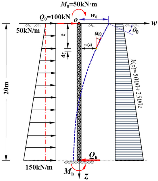
Figure 5.
Comparison and verification model of diaphragm wall.
To verify the correctness of the power series solution, the finite element solution for the comparison and verification model was obtained. Based on the theory of beams on elastic subgrade, the beam element was used to simulate the pile, and the linear springs distributed along the pile were adopted to simulate the subgrade resistance. The finite element calculation program for the rod system was developed. Its constitutive relationship is consistent with the proposed power series solution model. The element length in the finite element calculation is 0.5 m.
Figure 6 shows the comparison between the first 25 terms solution and the finite element solution of horizontal displacement, rotation angle, bending moment, and shear force. For the supporting conditions in Figure 6, three different types are presented: the top of the pile(wall) is free, and the bottoms of the pile(wall) are free, hinge, and fixed.
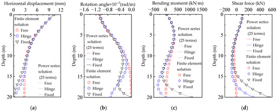
Figure 6.
Comparison of deflection deformation and internal force under different support conditions: (a) horizontal displacement; (b) rotation angle; (c) bending moment; and (d) shear force.
As can be seen from Figure 6, the power series solution and the finite element solution have a good consistency in terms of quantity value and variation law. It indicates the correctness of the proposed power series calculation method of pile(wall) deflection deformation with trapezoidal distributed subgrade reaction coefficients and lateral loads. The calculation results fully reflect the deflection deformation characteristics and the internal forces variation laws, and reflect the influence of support conditions on the working characteristics of the pile(wall).
Table 2 presents the maximum error of the horizontal displacement between the power series solution and the finite element solution under different pile bottom support conditions. It indicates the accuracy of the proposed power series calculation method.
Table 2.
Maximum error of horizontal displacement between power series solution and finite element solution under different pile bottom support conditions.
3.3. Influence of the Number of Terms in Power Series Solution on Calculation Accuracy
The power series solution of pile(wall) deflection deformation is an approximate solution. In order to discuss the convergence and calculation accuracy of the power series solutions, let the example in Section 3.2 be m = 500 kN/m4, k0 = 500 kN/m3, q = 0 kN/m, and qt = 0 kN/m. Under the support conditions that both ends of the pile(wall) are free, with all other parameters remaining unchanged, the number of terms in power series solution is taken 15, 16, 18, 20, 21, 23, 24, and 25, respectively, for calculation and analysis.
Figure 7 shows the variation in relative error with the number of calculation terms, in which the relative error is the power series solution with different numbers of calculation terms and the power series solution with 25 calculation terms. As shown in Figure 7, as the number of calculation terms increases, the relative error of the horizontal displacement at the same depth gradually decreases, indicating that the power series solution is convergent. When the number of calculation terms remains unchanged, as the calculation depth of the pile(wall) increases, the relative error increases. The reason is that the power series solution is an approximate solution, and its calculation accuracy is related to the truncation error O(z21). As z increases, the truncation error also increases.
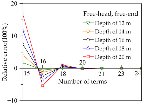
Figure 7.
Horizontal displacement power series solution comparison of different calculation terms and 25 calculation terms.
Table 3 shows the comparison of the calculation results of the pile(wall) bottom horizontal displacement and rotation angle when the number of calculation terms is 20 and 21. The truncation errors of the horizontal displacement and rotation angle are −0.00797 mm and −0.00159 × 10⁻³ rad/m, respectively. The relative truncation errors, which are defined as the ratio of the truncation error to the displacement w20 and the rotation angle θ20 when the number of calculation terms is 20, are −0.19% and 1.28%, respectively. Based on a comprehensive analysis of the maximum truncation error, the maximum relative truncation error, and the computational workload, when the number of terms in power series solution is 20, its calculation accuracy can meet the requirements of theoretical analysis and engineering design.
Table 3.
Horizontal displacement and rotation angle comparison at pile(wall) bottom with calculation terms 20 and 21.
3.4. Applicability of Power Series Solution
When the m-method is used to solve the deflection deformation and internal forces of the pile, to ensure the rationality and accuracy of the calculation, the concept of converted depth is provided from the perspective of long piles, that is, . When the conversion depth exceeds a certain value, the constraint type of the pile bottom has very little influence on the force and deformation near the top of the pile. At this point, the pile can be regarded as an infinite length pile. In the m-method, it is recommended that when > 4 m, the calculation should be performed with = 4 m. It can control the error, significantly simplify the calculation process, and eliminate the need to consider the boundary conditions at the pile bottom. This suggestion has been applied to the current design standards and specifications [4].
Based on the example in Section 3.2, the effective calculation depth of the power series solution with trapezoidal distributed subgrade reaction coefficients is discussed. To eliminate the influence of lateral loads on the results, let q = 0 kN/m and qt = 0 kN/m. The relationship between the actual pile(wall) length and the converted depth is shown in Table 4.
Table 4.
Relationship between actual pile(wall) length and converted depth.
The horizontal displacement curves of the pile(wall) at different converted depths are shown in Figure 8. When ≤ 5 m, the horizontal displacement power series solution will change with the increase in converted depth, and the horizontal displacement power series solution curve is in good agreement with the finite element solution curve. However, when > 5 m, the power series solution and the finite element solution are in good agreement in the upper section of the pile(wall), but the horizontal displacement gradually deviates from the finite element solution in the lower section of the pile(wall). In the m-method, when > 4 m, it should be calculated as = 4 m. Based on a large number of trial calculations, considering the displacement distribution rationality and the calculation accuracy, the proposed method suggests that when > 5 m, it should be calculated as = 5 m.
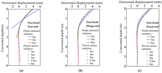
Figure 8.
Influence of different converted depths on power series solution: (a) pile(wall) bottom free; (b) pile(wall) bottom hinge; and (c) pile(wall) bottom fixed.
3.5. Engineering Application
Case 1: Figure 9 shows a case from reference [24]. The diameter of the reinforced concrete cast-in-place pile is 1.0 m, the length of the pile above ground is 3 m, the length of the pile below ground is 15 m, and the elastic modulus is Ep = 2.7 × 10⁷ kPa. The proportional coefficient of the subgrade reaction coefficients is m = 15,000 kN/m4, the subgrade reaction coefficient at the ground level is non-zero. At the top of the pile, there are horizontal load Q0 = 30 kN and bending moment M0 = 45 kN·m. There is no load acting on the side of the pile.
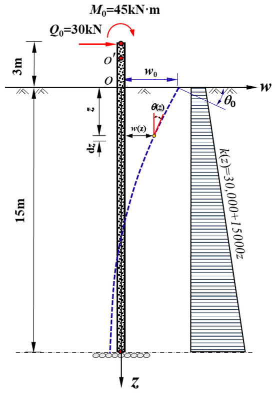
Figure 9.
Schematic diagram of Case 1.
As the subgrade reaction coefficient at the ground level is non-zero, reference [24] followed the approach in reference [19] and moved the coordinate origin O up by distance z0 = 2 m to the point O’. Regarding OO’ as virtual pile segment, the pile deflection deformation and internal force are calculated according to the m-method. As the converted depth > 4 m, reference [24] took = 4 m for calculation and only calculated up to a depth of 6.02 m. To be consistent with it, the calculation depth is also 6.02 m in the proposed power series calculation method.
Table 5 shows the comparison of the power series solution, the solution in reference [24], and the finite element solution. The maximum relative errors of the method in reference [24] relative to the finite element solution are 5.44% for bending moment and 3.72% for shear force, respectively. The maximum relative errors of the power series solution relative to the finite element solution are 0.13% for bending moment and 0.44% for shear force, respectively. The proposed power series calculation method has a smaller relative error compared to the method in reference [24]. The correctness and accuracy of the power series solution have been further verified.
Table 5.
Comparison of power series solution, solution in reference [24], and finite element solution.
In addition, the method used in reference [24] can only calculate the situation where there is no lateral load acting on the pile. If there are lateral loads, the calculation results will be affected by the coupling term αβ of α and β, and the method in reference [24] is not applicable. In engineering practice, various changes in working conditions can lead to lateral loads acting on pile(wall). Therefore, compared with the proposed power series calculation method, the method in reference [24] has certain limitations.
Case 2: Test pile IV# of Fuyu Songhua River Bridge from reference [25]. Geotechnical conditions are as follows: from 0 m to 14 m, it is saturated medium dense sand; from 14 m to 17 m, it is saturated medium dense coarse sand; from 17 m to 21 m, it is semi-hard dense sandy clay. The diameter of the reinforced concrete cast-in-place pile is 1.62 m, the length of the pile is 18.8 m, and the elastic modulus is Ep = 6.3 × 10⁶ kPa. The parameter α = 0.367 m−1, and the reverse calculation from α yields m = 17,800 kN/m4. At the top of the pile, there are horizontal load Q0 = 600 kN and bending moment M0 = 150 kN·m. The measured horizontal displacement at pile top w0 = 4.04 mm and the measured rotation angle at pile top θ0 = −1.05 × 10⁻³ rad/m. In the reference, the measured values of the bending moment are only provided for seven points within the range of 0 m to 10 m.
According to the reference, the soil layers are simplified to a single layer of saturated medium dense sand. As the pile bottom is located in a semi-hard dense sandy clay layer, it is calculated based on the fixed support condition at the pile bottom. The computed width b0 = 0.9 × (1 + D) = 2.358 m. The m value obtained by inversely calculating with the α value is 17,800 kN/m4. Since the data provided in the reference cannot directly calculate k0, the value of k0 is considered as follows: According to the experience data, the recommended value of k0 is 15,000 kN/m3 to 25,000 kN/m3 for medium dense sand [26]. However, since this case is saturated medium dense sand, the value of k0 will be reduced. If a 50% reduction is considered, k0 will range from 7500 kN/m3 to 12,500 kN/m3. To explore the appropriate value of k0, the power series solution for the pile bending moment is calculated when k0 is set at 7500 kN/m3, 12,500 kN/m3, 15,000 kN/m3, and 25,000 kN/m3, respectively.
Figure 10 shows the comparison of the power series solution, the m-method solution and the measured results. When k0 = 0 kN/m3, the subgrade reaction coefficients are triangular distribution, which corresponds to the m-method. When k0 ≠ 0 kN/m3, the subgrade reaction coefficients are trapezoidal distribution. Figure 10 presents the calculation results of the bending moment. Compared with the m-method solution, the power series solution with the trapezoidal distributed subgrade reaction coefficients has a better agreement with the measured values. This also indicates that in engineering practice, the distribution of the subgrade reaction coefficients is closer to a trapezoidal distribution rather than a triangular distribution. For different values of k0, in this case, when k0 is reduced by 50% of the recommended maximum value, it best matches the measured maximum bending moment value. When k0 is reduced by 50% of the recommended minimum value, it has a better overall agreement with the measured values. The measured maximum bending moment value is 1130.0 kN·m at a depth of 3.6 m. The power series solution (k0 = 2500 kN/m3) is 1131.8 kN·m, while the m-method solution is 1369.8 kN·m. Compared to the measured value, the relative errors of the power series solution and the m-method solution are 0.16% and 21.22%, respectively. The calculation accuracy of the proposed power series calculation method is higher than that of the m-method, and it has better engineering applicability compared with the m-method.
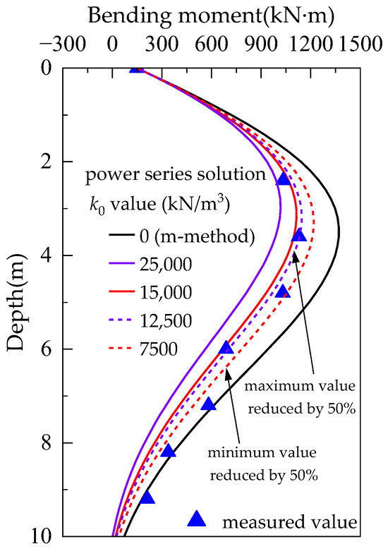
Figure 10.
Bending moment comparison of power series solution, m-method solution, and measured results.
4. Conclusions
The power series calculation method of pile(wall) deflection deformation with trapezoidal distributed subgrade reaction coefficients is proposed. The deflection deformation and internal forces of pile(wall) with trapezoidal distributed subgrade reaction coefficients under lateral loads are solved. The traditional K-method and m-method are expanded, and the theory of pile(wall) deflection deformation calculation is enriched.
The accuracy and rationality of the power series solution are verified by using the finite element calculation results and the engineering practice cases. Through the convergence analysis and the calculation accuracy of the horizontal displacement power series solution, the minimum number of calculation terms in power series solution that meets the accuracy requirements of theoretical analysis and engineering design is 20. Based on the distribution laws analysis of pile(wall) deflection deformation and internal forces, it is suggested that when the converted depth > 5 m, it should be calculated as = 5 m.
The proposed power series calculation method is clear in concept and simple in calculation. It solves the problem of the small deflection deformation calculation of pile(wall) with trapezoidal distributed subgrade reaction coefficients in elastic ground. The proposed method can be applied to the solution of various geotechnical engineering problems such as foundation pit and slope engineering. Subsequently, it can also be further extended to the deflection deformation calculation of pile(wall) in multi-layered ground or in complex engineering conditions with local loads.
Author Contributions
Conceptualization, X.W. and G.J.; methodology, X.W., Y.M. and G.J.; software, Y.M., H.K. and Y.Z.; validation, X.W. and Y.M.; formal analysis, X.W.; investigation, H.K.; resources, G.J.; data curation, Y.Z.; writing—original draft preparation, Y.M.; writing—review and editing, X.W.; visualization, Y.M.; supervision, X.W.; project administration, X.W.; funding acquisition, X.W. All authors have read and agreed to the published version of the manuscript.
Funding
This research was funded by Scientific Research Project of Shanghai Tunnel Engineering Co., Ltd., grant number 2021-SK-21.
Data Availability Statement
The original contributions presented in this study are included in the article. Further inquiries can be directed to the corresponding author.
Conflicts of Interest
Author You Zhou was employed by the company Shanghai Tunnel Engineering Co., Ltd. The remaining authors declare that the research was conducted in the absence of any commercial or financial relationships that could be construed as a potential conflict of interest. The sponsors had no role in the design, execution, interpretation, or writing of the study.
Appendix A
The calculation coefficients in Equations (6)–(9) are as follows:
Appendix B
Appendix B.1. Calculation Formulas of the Unknown Initial Values for Pile(Wall) Top Under Free Support Condition
The known pile(wall) top loads are M0, Q0. The lateral loads q and qt act on the full height of the pile(wall).
The calculation formulas of the unknown initial values for pile(wall) top under free support condition are as follows:
The calculation coefficients corresponding to Formula (A25) are shown in Table A1.
Table A1.
Calculation coefficients corresponding to Formula (A25).
Table A1.
Calculation coefficients corresponding to Formula (A25).
| Pile(Wall) Bottom Support Condition | Calculation Coefficients |
|---|---|
| Free | |
| Hinge | |
| Fixed |
Appendix B.2. Calculation Formulas of the Unknown Initial Values for Pile(Wall) Top Under Hinge Support Condition
The known pile(wall) top load is M0 and the known pile(wall) top displacement is w0. The lateral loads q and qt act on the full height of the pile(wall).
The calculation formulas of the unknown initial values for pile(wall) top under hinge support condition are as follows:
The calculation coefficients corresponding to Formula (A26) are shown in Table A2.
Table A2.
Calculation coefficients corresponding to Formula (A26).
Table A2.
Calculation coefficients corresponding to Formula (A26).
| Pile(Wall) Bottom Support Condition | Calculation Coefficients |
|---|---|
| Free | |
| Hinge | |
| Fixed |
Appendix B.3. Calculation Formulas of the Unknown Initial Values for Pile(Wall) Top Under Fixed Support Condition
The known pile(wall) top displacements are w0, θ0. The lateral loads q and qt act on the full height of the pile(wall).
The calculation formulas of the unknown initial values for pile(wall) top under fixed support condition are as follows:
The calculation coefficients corresponding to Formula (A27) are shown in Table A3.
Table A3.
Calculation coefficients corresponding to Formula (A27).
Table A3.
Calculation coefficients corresponding to Formula (A27).
| Pile(Wall) Bottom Support Condition | Calculation Coefficients |
|---|---|
| Free | |
| Hinge | |
| Fixed |
References
- Race, P.E. Theory of lateral bearing capacity of piles. In Proceedings of the 1st International Conference on Soil Mechanics and Foundation Engineering, Cambridge, MA, USA, 22–26 June 1936. [Google Scholar]
- Broms, B.B. Lateral resistance of piles in cohesive soils. J. Soil Mech. Found. Div. 1964, 90, 27–63. [Google Scholar] [CrossRef]
- Reese, L.C.; Cox, W.R.; Koop, F.D. Analysis of laterally loaded piles in sand. In Proceedings of the 6th Annual Offshore Technology Conference, Houston, TX, USA, 6–8 May 1974. [Google Scholar]
- JTG 3363–2019; Specifications for Design of Foundation of Highway Bridges and Culverts. Ministry of Transport of the People’s Republic of China: Beijing, China, 2019.
- Hu, R. New method for pile foundation calculation. Railway Std. Desn. Comm. 1964, 1, 18–22+8. [Google Scholar] [CrossRef]
- Bridge and Tunnel Group of the Design Team of Wuhan Railway Bureau. Simplified calculation method of pile foundation cap by m-method. Bridge Constr. 1974, 2, 17–47. [Google Scholar]
- Fan, W. Static Calculation of Underground Wall (Column); People’s Railway Press: Beijing, China, 1978; pp. 50–55. [Google Scholar]
- Xu, G. Discussion on several issues concerning the calculation of elastic resistance of soil in the m-method for foundation of bridge piers and abutments. Railway Std. Desn. Comm. 1984, 10, 12–19. [Google Scholar] [CrossRef]
- Zhou, X. Unified expression for the calculation coefficients of the m-method for pile foundations. Highway 1993, 6, 18–22. [Google Scholar]
- Poulos, H.G.; Davis, E.H. Pile Foundation Analysis and Design; John Wiley & Sons Inc.: Hoboken, NJ, USA, 1980; pp. 163–232. [Google Scholar]
- Wei, L.; Zhang, C.; Zhai, S.; He, Q.; Li, H. Analysis of lateral cyclic loaded pile considering weakening effect of m value. J. Central South Univ. (Sci. Tech.) 2018, 49, 2272–2279. [Google Scholar] [CrossRef]
- Wang, G.; Zhang, Y.; Lu, H.; Ji, C.; Peng, X. Research on the horizontal static load test of the single pile in the muddy soil foundation. Eng. J. Wuhan Univ. 2020, 53, 125–129. [Google Scholar]
- Chen, Y. Report on the Determination of the Proportional Coefficient m for the Subgrade Reaction Coefficients of Bridge Pile Foundations in Soft Soil Areas; China Railway Siyuan Survey and Design Group Co., Ltd.: Wuhan, China, 2020. [Google Scholar]
- Chen, T.; Xi, S.; Qian, C.; Wang, P.; Zhu, M.; Liang, Z. Study on the Soil–Pile Interaction of Slender Piles in Multi-Layered Soil by the Variational Analysis Method. Buildings 2024, 14, 4055. [Google Scholar] [CrossRef]
- Yang, Y.; Ma, H.; Hu, Z.; Wang, L.; Chen, X. The Calculation Method for the Horizontal Bearing Capacity of Squeezed Branch Piles Considering the Plate–Soil Nonlinear Interaction. Appl. Sci. 2023, 13, 13229. [Google Scholar] [CrossRef]
- Wang, J.P.; Su, J.B.; Wu, F.; Zhang, Z.; Lv, Y. Lateral dynamic load tests of offshore piles based using the m-method. Ocean Eng. 2021, 220, 108413. [Google Scholar] [CrossRef]
- Liu, L.; Xiao, L.; Liu, Y.; Zhao, M.; Jin, F.; Li, X.; Tian, Y. Horizontal Bearing Characteristics of Large-Diameter Rock-Socketed Rigid Pile and Flexible Pile. Buildings 2025, 15, 768. [Google Scholar] [CrossRef]
- Wang, D. Elastic pile calculation for trapezoidal distributed subgrade reaction coefficients. Bridge Constr. 1976, 5, 35–45. [Google Scholar]
- Zhan, Z. Calculating method for low-pile cap resistance based on the soil elastic resistance in trapezoidal distribution. J. Changsha Railway Inst. 1979, 4, 39–50. [Google Scholar] [CrossRef]
- Mao, J.; Xu, J.; Yang, L. An improved method for stabilizing pile by using m-method model to the whole pile. Rock Soil Mech. 2018, 39, 1197–1202. [Google Scholar] [CrossRef]
- Deng, T.; Xu, J.; Zheng, J.; Zheng, L. Modified cantilever pile method for anti-sliding pile in deep soft soil. Rock Soil Mech. 2022, 43, 1299–1305+1316. [Google Scholar] [CrossRef]
- Lu, H.; Chen, L. A modified m-method in the analysis of laterally loaded pile. J. N. China Inst. Water Conserv. Hydroelectr. Power 2011, 32, 123–125. [Google Scholar] [CrossRef]
- Deng, T.; Lin, C.; Liu, Z.; Huang, M.; Chen, W. A simplified elastoplastic method for laterally loaded single pile with large displacement. Rock Soil Mech. 2020, 41, 95–102. [Google Scholar] [CrossRef]
- Zhao, M. Bridge Pile Foundation Calculation and Inspection; China Communication Press: Beijing, China, 2000; pp. 62–64. [Google Scholar]
- Wu, H. The total process nonlinear analysis of lateral loaded pile and witch controlled design—Composite stiffness principle with bi-parameter method. J. Chongqing Jiaotong Univ. 2001, 20, 77–82. [Google Scholar]
- Huang, Y.; He, F.S. Beams, Plates, and Shells on Elastic Foundations; Science Press: Beijing, China, 2005; p. 18. [Google Scholar]


Disclaimer/Publisher’s Note: The statements, opinions and data contained in all publications are solely those of the individual author(s) and contributor(s) and not of MDPI and/or the editor(s). MDPI and/or the editor(s) disclaim responsibility for any injury to people or property resulting from any ideas, methods, instructions or products referred to in the content. |
© 2026 by the authors. Licensee MDPI, Basel, Switzerland. This article is an open access article distributed under the terms and conditions of the Creative Commons Attribution (CC BY) license.