1. Introduction
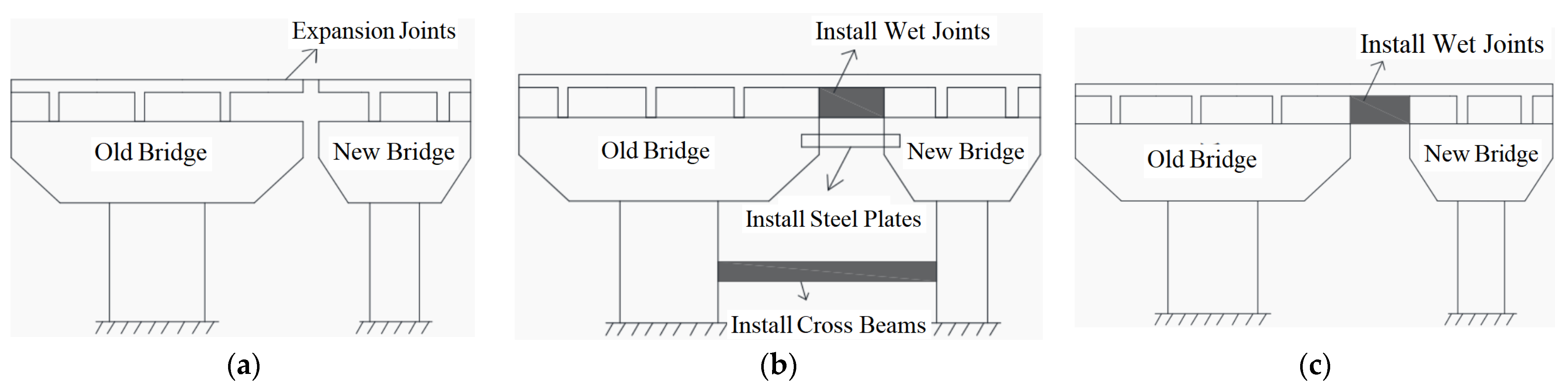
With the continuous increase in traffic volume, bridge widening projects have become an important means to enhance the capacity of existing routes. In the reconstruction of an existing straight bridge, the transverse splicing method between the old and new sections plays a crucial role. The old bridge has largely stabilized in terms of contraction, creep, and settlement during the expansion process, whereas the new bridge is still in its development stage. During this period, continuous settlements may occur at piers due to concrete creep and foundation consolidation factors, leading to vertical misalignment between the old and new deck surfaces and resulting in significant bending stresses. Currently, three main splicing methods are employed [
1,
2]: independent connection; full connection; and upper structure connected with lower structure remaining independent. These methods are illustrated in
Figure 1.
The three connection methods illustrated in
Figure 1 can, to varying degrees, ensure the transverse overall stability and service continuity between the old and new bridge sections, thereby satisfying requirements for smooth traffic flow. However, none of these approaches can completely prevent the adverse effects caused by differential settlement and shrinkage-creep mismatch, only mitigating them to different extents. Luo, J. [
3] indicated that settlement of bridge piers can significantly increase the local stresses at expansion joints. Jiang, M., et al. [
4] further clarified that foundation settlements inevitably lead to uneven deformation in the superstructure. Due to differences in foundation conditions and construction sequences between new and existing bridges, such differential settlements are nearly unavoidable, resulting in additional interface stresses at the joint that greatly exceed conventional material strength limits. Therefore, cracking at expansion joints is not primarily caused by insufficient flexural tensile capacity of materials but rather results from stress concentrations induced by constrained deformations due to settlement disparities. Traditional joint reinforcement techniques have proven inadequate for effectively controlling these high-stress states; thus, developing an active control device capable of regulating differential settlement-induced deformations represents a key approach for addressing this issue.
To address this technical challenge, numerous systematic studies have been conducted by domestic researchers. Li, Z. [
5], utilizing finite element simulations, analyzed the structural stress impacts of different connection methods on concrete beam bridge widening. The findings indicated that rigid connections are most unfavorable at the splice locations and proposed optimization schemes to provide critical parameters for design. Guo, Y. et al. [
6], taking prestressed concrete T-beam bridges as an example, employed multi-condition finite element analyses to confirm that foundation settlement differences significantly affect support transverse beams; when settlement disparities are controlled within 2 mm, the spliced regions can still meet load-bearing requirements, thus providing a basis for engineering standards formulation. Yang, Y. [
7] and Zhang, C. et al. [
8], through combined approaches of “field measurements, numerical simulations, and theoretical validation”, revealed second-order distribution patterns of main girder settlements in new bridges and clarified the relationship between joint stresses and permissible settlement differences via sensitivity analysis. Furthermore, Zhao, Y. [
9] and Han, X. [
10] conducted in-depth investigations from perspectives such as internal force factors, foundation settlement control methods, and creep effects; they established comprehensive theoretical frameworks covering design principles, construction practices, and monitoring strategies. Additionally, numerous scholars [
11,
12,
13,
14,
15] have extensively explored issues related to joint stress distribution and bridge widening construction schemes—these studies offer valuable practical experience coupled with a solid theoretical foundation for engineering applications.
Significant advancements have been made in international research. Meng, J. et al. [
16], through monitoring and analysis, identified that after widening medium and small-span concrete slab bridges, the shrinkage and creep of new girders induce tensile stresses that may lead to cracking, providing a basis for crack-resistant design strategies. Jiang, M. et al. [
4] proposed an approach integrating probabilistic limit state methods into foundation settlement analysis, thereby enhancing the theoretical framework for non-uniform settlements. Patrício, J. D. et al. [
17], utilizing finite element models, investigated soil–structure interaction effects, highlighting that construction phases, creep phenomena, and foundation uplift significantly influence subgrade deformation patterns; this contributes to understanding long-term settlement behavior during bridge widening. ElSafty et al. [
18,
19] conducted reviews of bridge deck design practices emphasizing their critical role in maintaining structural integrity. An anonymous study [
20], using Oyster Channel Bridge as a case example, validated a “rigid load transfer” reinforcement scheme; the method for matching stiffness between existing and new structures has been incorporated into international standards. Ahlgrimm, J. [
21], through experimental testing and numerical simulations, identified vulnerabilities at connection nodes and proposed flexible joint solutions with localized reinforcements aimed at reducing fatigue damage risks. In terms of bridge reconstruction: Tarawneh, et al. [
22,
23] employed heavy vehicle simulators to evaluate ultra-lightweight UHPC decks; Samtani N C [
24] developed standardized probabilistic charts to guide differential settlement control measures; and Wu, W. et al. [
25] verified that quadratic curve models effectively describe lateral displacement of precast hollow slabs—providing support for finite element analyses. Furthermore, Asgari, A., et al. [
26] compared seismic responses of shallow piles versus raft foundations on saturated versus dry sites to reveal how soil–foundation–structure interactions influence dynamic characteristics—a valuable reference for widening projects in soft ground regions. Bagheri, M., et al. [
27] demonstrated that integrated shear walls can enhance seismic resilience—offering insights applicable to foundation design in soft soils. Additionally, other scholars [
28,
29,
30,
31,
32] proposed a novel transverse joint structure specifically designed for the widening of long-span concrete continuous box girder bridges, aiming to effectively address deformation issues in widening projects.
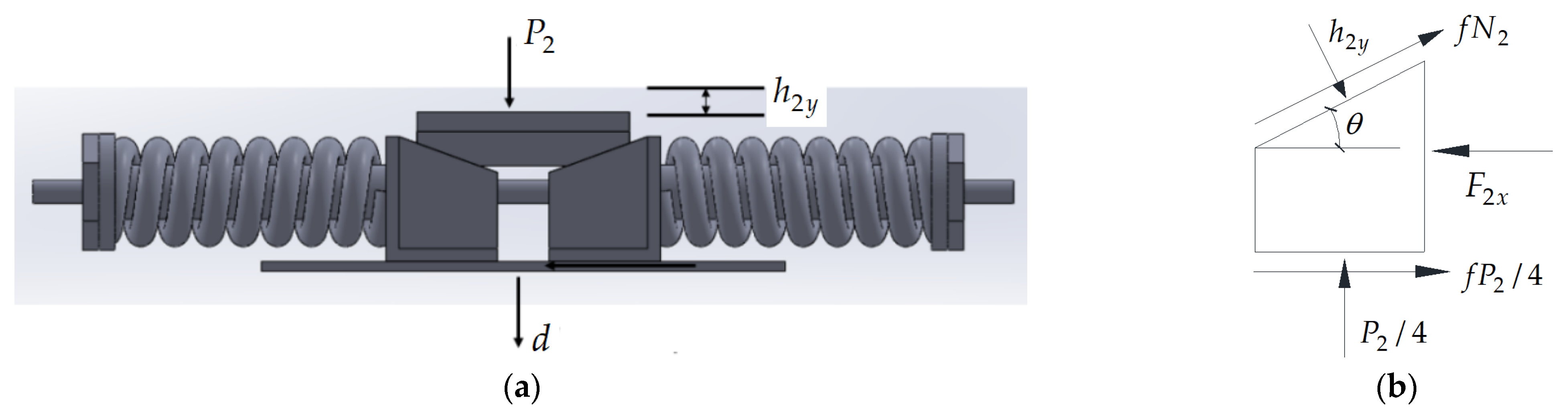
Despite the substantial achievements in existing research, technical bottlenecks still exist in actively controlling differential settlement and reducing stress at joint areas. In response to this, this paper proposes a “Adaptive Rebound Displacement Compensation Device” for settling bridge piers, as illustrated in
Figure 2. This device aims to achieve dynamic control of differential settlement from a structural design perspective. Through the adaptive rebound of the bearings, it can control the bridge deck settlement to 10–20% of the pier settlement, significantly lowering the bending stresses in the joint area compared to traditional design solutions.
The front and top views of
Figure 2 depict the core structure of the device. Its key innovation lies in its ability to achieve efficient displacement regulation and structural protection when vertical displacements are induced by settlement of new piers. The device is designed to address both structural safety and traffic functionality requirements. Firstly, it employs pre-tensioned springs to counteract the downward movement of the bridge deck caused by pier settlement, significantly reducing the loss-of-stiffness values and displacement responses of the superstructure. This mechanism effectively mitigates issues such as cracking and stiffness degradation in concrete pavements and upper structures resulting from foundation settlements. Secondly, the device can effectively minimize differential settlement across the bridge deck, maintaining a smooth surface at expansion joints; thus, it also enhances riding comfort and reduces impact loads on vehicles during widening or reconstruction processes.
2. Theoretical Formulation of the “Adaptive Rebound Displacement Compensation Device” for Bridge Piers
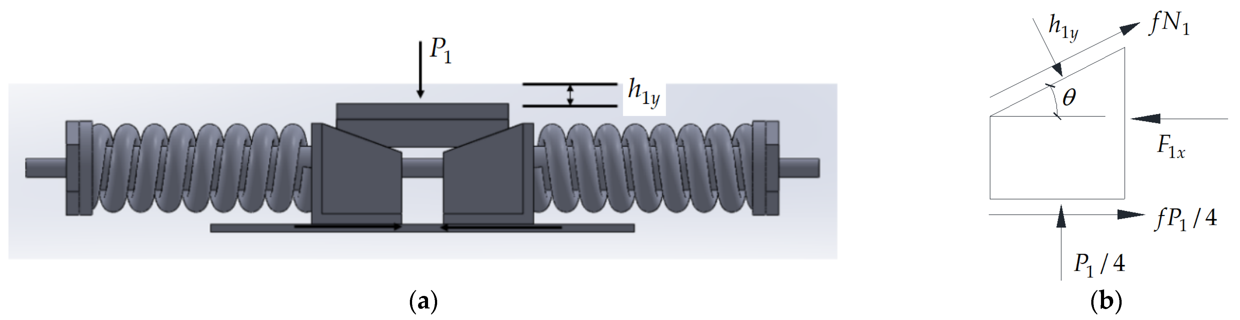
Under the condition of solely the bridge’s gravity acting on the device, the overall force state is illustrated in
Figure 3. The pressure exerted by the bridge is denoted as
. Under the action of force
, the vertical displacement of the bridge deck is
. Four springs participate in regulating the displacement. For analysis, a single spring and its associated L-shaped baffle plate are considered, as shown in
Figure 3b. Let the angle between the inclined plane of the L-shaped baffle and the horizontal direction be
. The friction coefficients between each friction surface of the device are assumed to be
. Decomposing
along the inclined plane yields the normal force
acting perpendicular to the inclined surface. Resolving
into the horizontal component
along the X-direction gives the force experienced by a single spring.
When the new bridge pier has not experienced settlement, only gravity acts on the device. The pre-tensioned force in the springs balances the bridge-exerted pressure
, maintaining the entire device in equilibrium. At this stage, the two L-shaped plates do not slide. Based on
Figure 3b and static equilibrium conditions, the vertical (Y-direction) equilibrium equation for the L-shaped plate is
which yields
The horizontal (X-direction) equilibrium equation for the L-shaped plate is
Combining Equations (2) and (3), we obtain
Let
denote the total stiffness coefficient of the four springs; therefore, the stiffness coefficient of a single spring is
. Under horizontal thrust
, the horizontal displacement of the L-shaped baffle is
Under the influence of the pre-tensioned springs, the two L-shaped plates slide inward, causing the upper cover plate to produce an upward vertical displacement. Based on geometric relationships, the vertical displacement of the trapezoidal plate is
When the settlement of the new bridge pier reaches a value of
, the pier will experience a loss of force (i.e., a loss of a portion of its load-bearing capacity). At this time, the force condition of the device is illustrated in
Figure 4.
Let the pressure acting on the device at this time be
, where
represents the loss of load in the bridge pier after the settlement. The pre-tensioning forces from the springs on both sides will cause the two L-shaped baffle plates to slide. Let the pressure acting on the inclined plane from a single spring be
and the spring pre-tension force be
. According to
Figure 4b and the conditions of static equilibrium, the equilibrium equation for the L-shaped plate in the Y-direction is given by
From this, we can solve for
The equilibrium equation in the X-direction is
By combining Equations (8) and (9), we can obtain
At this point, the horizontal displacement of the L-shaped plate is
and the vertical displacement is
From the above two states, we can derive the vertical displacement difference of the trapezoidal plate, which represents the opposite displacement supported by the adaptive device when the new bridge pier settles. Thus, the settlement
of the widened new bridge deck is given by
Assuming the overall equivalent stiffness of the bridge superstructure is denoted as
, this equivalent stiffness
was calculated in
Section 3.1 based on the relationship between “total external force” and “overall displacement”. This calculation sufficiently supports the coupled analysis of pre-tensioning forces within the device and deck displacements, with local stiffness variations having negligible impact on the primary conclusions. Additionally, this simplification adheres to the principle of mechanical equivalence by separating self-weight-induced displacements from external load-induced displacements to determine the corresponding net deformation stiffness. The distributed stiffness is then approximated as a lumped parameter, ensuring that overall force equilibrium and deformation compatibility are maintained within the system. Let the loss of force
in the bridge superstructure when the bridge pier settles by
be
Substituting (13) into (14) yields
where
denotes the overall stiffness of the four springs. A smaller difference in support forces results in better load conditions for the superstructure, leading to reduced tensile stress in the expansion joints. The specific dimensions of the adaptive rebound displacement compensation device are designed based on
. In the absence of the “Adaptive Rebound Displacement Compensation Device”, the loss of force is given by
Using Equations (15) and (16), we can compare the difference in loss of force in the bridge superstructure with and without the “Adaptive Rebound Displacement Compensation Device”.
The theoretical analysis in this section employs a quasi-static model to derive Equations (13)–(15), primarily based on three considerations: First, the study focuses on displacement compensation and structural loss mitigation performance of the adaptive device. The quasi-static approach decomposes the time-dependent process into discrete static equilibrium states, enabling direct establishment of quantitative relationships while avoiding the complexity associated with viscoelastic frameworks that could obscure the advantages of the device. Second, since the settlement rate of piers is much lower than the elastic response rates of both the bridge and device, each stable settlement stage can be approximated as a static equilibrium; thus, results obtained from this quasi-static model meet engineering accuracy requirements without necessitating numerous uncertain parameters inherent in viscoelastic models. Third, grounded in static equilibrium principles and Hooke’s law, this simplified model facilitates constructing straightforward algebraic equations that explicitly reveal coupling relationships between the bridge’s equivalent stiffness and spring stiffness. This approach avoids complex differential or integral equations characteristic of time-varying or viscoelastic frameworks, thereby providing an efficient basis for optimizing device design.
3. Determination of Physical Quantities for the Adaptive Rebound Displacement Compensation Device
3.1. Determination of Spring Preload Force
In the finite element software, the stiffness is calculated using the actual model. In the absence of self-weight, a vertical force of 20 kN is applied upwards at the bottom of the bridge, with the bottom area of the bridge being 1.68 × 107 mm2, which converts to pressure as 1.19 × 10⁻³ MPa. The simulation results indicate that the upward displacement at the mid-span of the bridge is h1 = 2.734 × 10⁻² mm.
In the presence of self-weight, finite element analysis shows that the mid-span displacement at the bottom of the bridge under self-weight conditions is h2 = 9.291 × 10⁻² mm, resulting in a final downward displacement at the bottom of the bridge of . Using knowledge from material mechanics, the overall stiffness of the bridge is calculated to be N/mm.
Based on theoretical derivation, the required preload force for a single spring and the length of compression of the spring can be obtained. It is noted that primarily represents the contact force exerted by the bridge’s self-weight on the connecting device. For simplification, is taken as the self-weight of the bridge. A solid model is established in SolidWorks 2022, and the volume of the span where the connecting device is installed is measured to be m3. Given that the density of C50 concrete is 2500 kg/m3, the mass of this span M is calculated to be 108,900 kg, resulting in a gravitational force N, thus N. Substituting the above data into Equation (2) yields N, and subsequently, the spring preload force N can be determined from Equation (3).
3.2. Determination of Friction Coefficient, Angle of L-Shaped Baffle, and Total Stiffness of Springs
According to Equation (15), the loss of force in the upper structure of the bridge is related to the bridge stiffness , total spring stiffness , angle of the L-shaped baffle, and the friction coefficient of the device’s contact surface. To minimize the loss of force , the relationships among these parameters need to be explored. From Equation (15), it is clear that is inversely proportional to the friction coefficient . The coefficient of friction between steel surfaces typically ranges from 0.1 to 0.15. In practical applications, the contact interfaces are often coated with lubricants such as grease to artificially reduce the friction coefficient. Additionally, this study employs a quasi-static model that simulates the stable state of gradual pier settlement. Small displacements in the range of 1–5 mm are unlikely to induce significant stick-slip behavior and have minimal impact on interface wear; thus, the friction coefficient can be considered constant under these conditions. For simplicity, is taken as 0.1.
Let the maximum allowable settlement of the new bridge foundation be
, where
d = 5 mm, and given
f = 0.1. Based on Equation (15), the relationship between the overall stiffness of the upper structure
, total spring stiffness
, and the loss of force
can be derived. In
Section 3.1,
was determined to be
N/mm. For values of
=
k/10,
k/20,
k/30,
k/40, and to ensure the device remains stable under the weight of the bridge, the value of
should not be too small. Here,
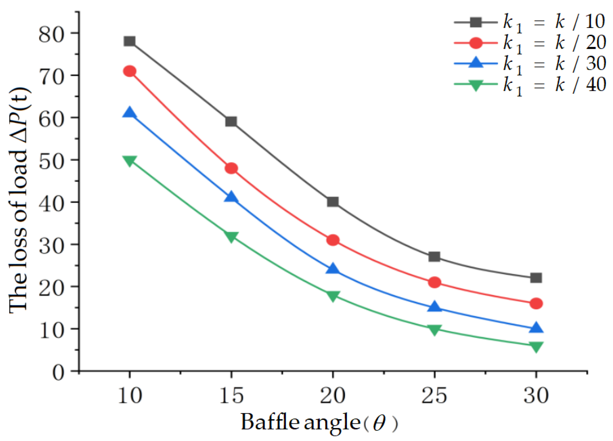
is taken at 10°, 15°, 20°, 25°, and 30°, and the relationship between
and
is plotted to find the optimal relationship between
and
, as shown in
Figure 5.
It can be observed that when
is determined, the loss of load value is minimized at
; thus, the final total spring stiffness is
N/mm.
Figure 5 indicates that the slope of the curve for
between 20° and 30° changes little. To ensure that the preload force of the spring in the device is effectively transmitted upward,
should not be set too high; hence,
is taken as 20°.
3.3. Determination of Spring Turns and Strength Verification
Section 3.2 has established the design parameters for the adaptive connecting device. The next step is to design the number of turns of the spring. Based on material mechanics, the shear modulus of the spring
, and the expressions for torsional section modulus and spring stiffness are given by
where
is the design wire diameter of the spring,
is the design number of turns, and
is the design coil diameter. Assuming the torque acting on a single spring is denoted as
, and based on
Section 3.1, the horizontal force exerted on the single spring is
. The relationship between these two quantities is expressed as
To ensure that the spring is not damaged during normal operation, a shear strength check must be performed. The spring material is silicon-manganese alloy steel wire, with an elastic modulus
GPa and a Poisson’s ratio
, and the allowable shear stress
. Taking the design wire diameter
mm and the design coil diameter
mm. From
Section 3.1 and
Section 3.2,
N and total spring stiffness
N/mm. Based on Equations (17) and (18), the number of spring turns is calculated as
, and the torque is
N·mm. Using the above data, the shear stress of the spring is obtained as
which satisfies the shear strength requirements of the spring.
4. Finite Element Simulation Analysis and Comparison of Bridge Deck Settlement Displacement with and Without the Adaptive Rebound Displacement Compensation Device
4.1. Finite Element Simulation Results and Analysis of the Adaptive Rebound Displacement Compensation Device Calculated Independently
In the global coordinate system, the transverse direction along the bridge deck is defined as the X direction, the longitudinal direction along the bridge deck is defined as the Z direction, and the vertical downward direction is defined as the Y direction. To facilitate the application of preload, four circular sleeves are used to replace the function of the springs. The sleeves are designed to have a gap with the four slender rods to prevent contact. The left end of the sleeve is bound to a spacer, while the right end is bound to the L-shaped baffle. The slender rods are respectively bound to the spacers and nuts at both ends, with the spacers also bound to the nuts. The upper cover plate is bound to the bottom of the T-shaped bridge, and displacement constraints are applied to the lower surface of the bottom steel plate. The settlement displacements are set to range from 1 mm to 5 mm. The four inclined cross-sections of the trapezoidal upper cover plate are in frictional contact with the four inclined cross-sections of the L-shaped baffle, and the two bottom surfaces of the L-shaped baffle are in frictional contact with the upper surface of the bottom steel plate, with a friction coefficient of 0.1.
The device components are primarily constructed from structural steel, with the exception of the springs. The elastic modulus and stiffness of the springs are specified according to the parameters established in
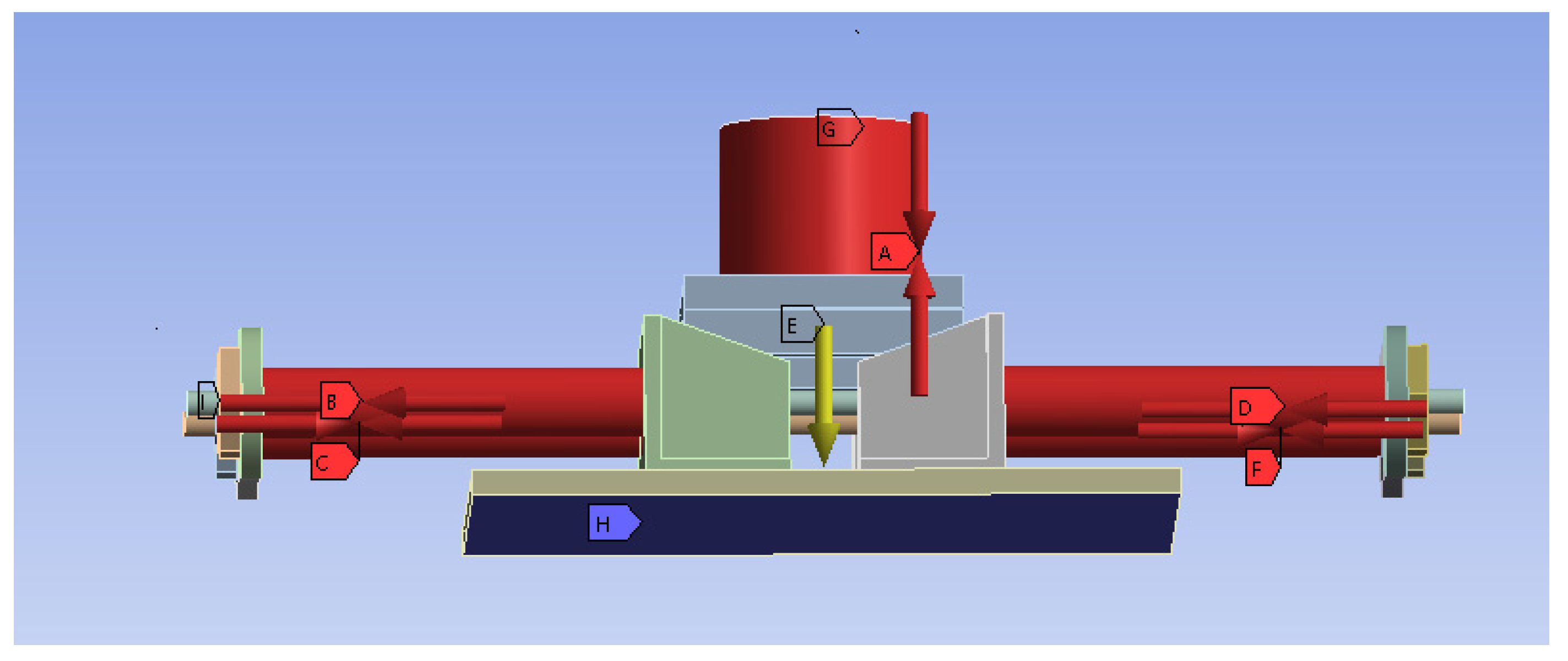
Section 3. A pre-tensioning force of 98 kN is applied to each spring at points B, C, D, and F as indicated in
Figure 6. The loading process employs a time-stepping approach: during the initial step, the pre-tightening force is applied; subsequently, five locking steps simulate how these forces gradually activate under foundation settlement conditions typical of real bridges, with forces decrease until equilibrium is reached. Displacement constraints are imposed on the bottom surface of the lower steel plate (point H in
Figure 6). Using a similar load-time stepping method divided into five stages, initially no vertical displacement occurs; then, in each subsequent stage, displacements ranging from 1 mm to 5 mm are simulated at point E (
Figure 6), representing different scenarios associated with foundation subsidence during bridge widening operations. To replicate potential loss-of-stiffness effects caused by pier foundation sinking on upper structure performance, an additional pre-tensioning force is exerted on a cylindrical element located at the top of the device (point A in
Figure 6). The top surface is fixed as shown at point G in
Figure 6. As shown in
Figure 6, since there are two devices at the front and back of a beam, this simulates half of the self-weight of a T-shaped beam, resulting in a preload force of
N.
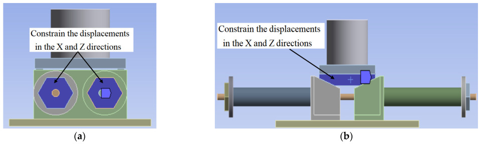
It is particularly important to ensure the accuracy of the simulation by constraining the X and Z directional displacements of the two faces at the front and back of the upper cover plate, as well as the four spacers at both ends, while allowing movement only in the Y direction. This ensures that the device does not move in any direction other than Y during settlement, as shown in
Figure 7, since the lower steel plate of the device is bound to the bridge cover beam in reality. Assuming the stiffness of the cover plate is infinitely large, the vertical displacement of any point on the upper cover plate can be extracted as the hypothetical settlement displacement of the bridge deck.
After setting the boundary conditions, simulation calculations are performed to analyze the five working conditions, where the pier settles from 1 mm to 5 mm, and the resulting displacements of the upper structure of the bridge are compared with the simulation results of the bridge without the adaptive connecting device. The comparison results are summarized in the table below.
Analysis of the table comparing bridge deck settlement displacements with and without the adaptive connecting device indicates that with the adaptive connecting device, the bridge deck settlement displacement increases linearly with the settlement of the pier, and the increment is relatively small. When the pier settles from 0 mm to 5 mm, the bridge deck displacement only increases from 0.031 mm to 0.523 mm. This is due to the upward force provided by the spring preload that counteracts the initial displacement caused by the self-weight of the upper structure. In contrast, without the device, the bridge deck settlement displacement exhibits a significant nonlinear increase with a large increment; under the same range of pier settlement, the bridge deck displacement surges from 0.042 mm to 4.926 mm. At each settlement node, the displacement of the bridge deck with the device is only about 11% of that without the device. This is consistent with the results from the theoretical design expressions presented in this paper and demonstrates that the device can effectively cushion the impact of pier settlement on the bridge deck, significantly reducing displacement and enhancing the safety and durability of the bridge. It is recommended for use in bridge engineering projects prone to settlement, with further research suggested on its performance and economic viability under extreme conditions.
Analysis of the data presented in
Table 1 indicates that, following the installation of the adaptive device, there is an approximately linear relationship between pier settlement and deck displacement. This behavior fundamentally arises from the linear elastic characteristic of the core springs, which obey Hooke’s law. During pier settlement, these springs generate a counteracting elastic restoring force that offsets most of the displacement load transmitted to the bridge deck. Within the 1–5 mm settlement range, the springs operate within their elastic limit; thus, their response remains linear. The connection design of the device ensures a load path with linear transmission characteristics and does not introduce additional nonlinear constraints, resulting in an overall linear relationship. Moreover, at a maximum settlement level of 5 mm, no stiffness degradation or nonlinear response is observed in the system. This is because within this displacement scope: (i) the spring deformation has not exceeded its elastomeric limit; therefore, its stiffness remains constant; and (ii) contact interfaces are stable without slip or collision phenomena—ensuring a stable load transfer pathway and maintaining predominantly linear system behavior.
4.2. Finite Element Results of the Overall Calculation with Adaptive Rebound Displacement Compensation Device Inserted in T-Beam Bridge
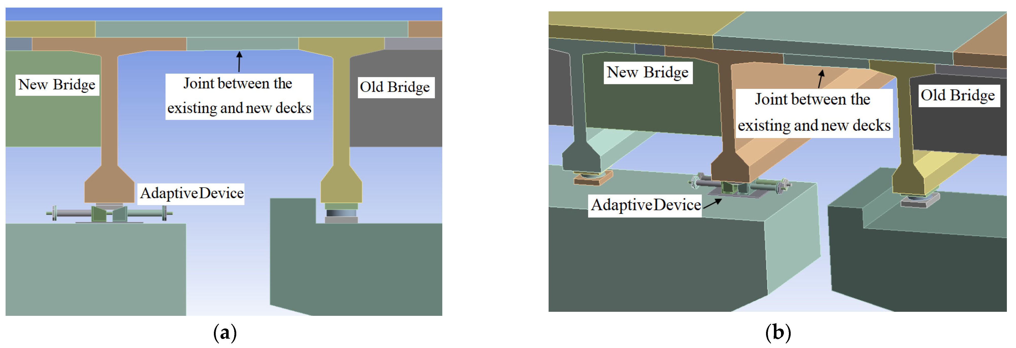
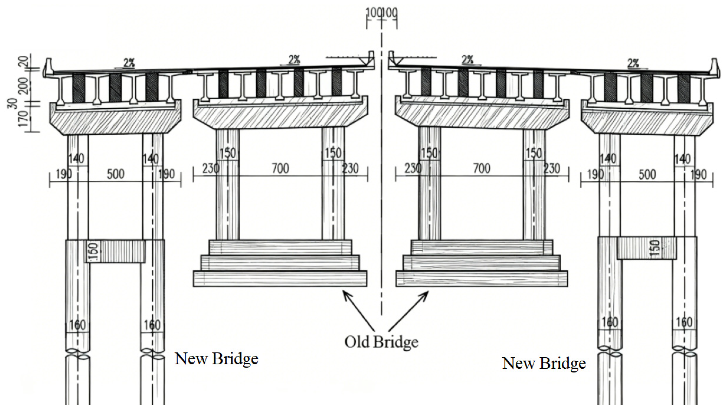
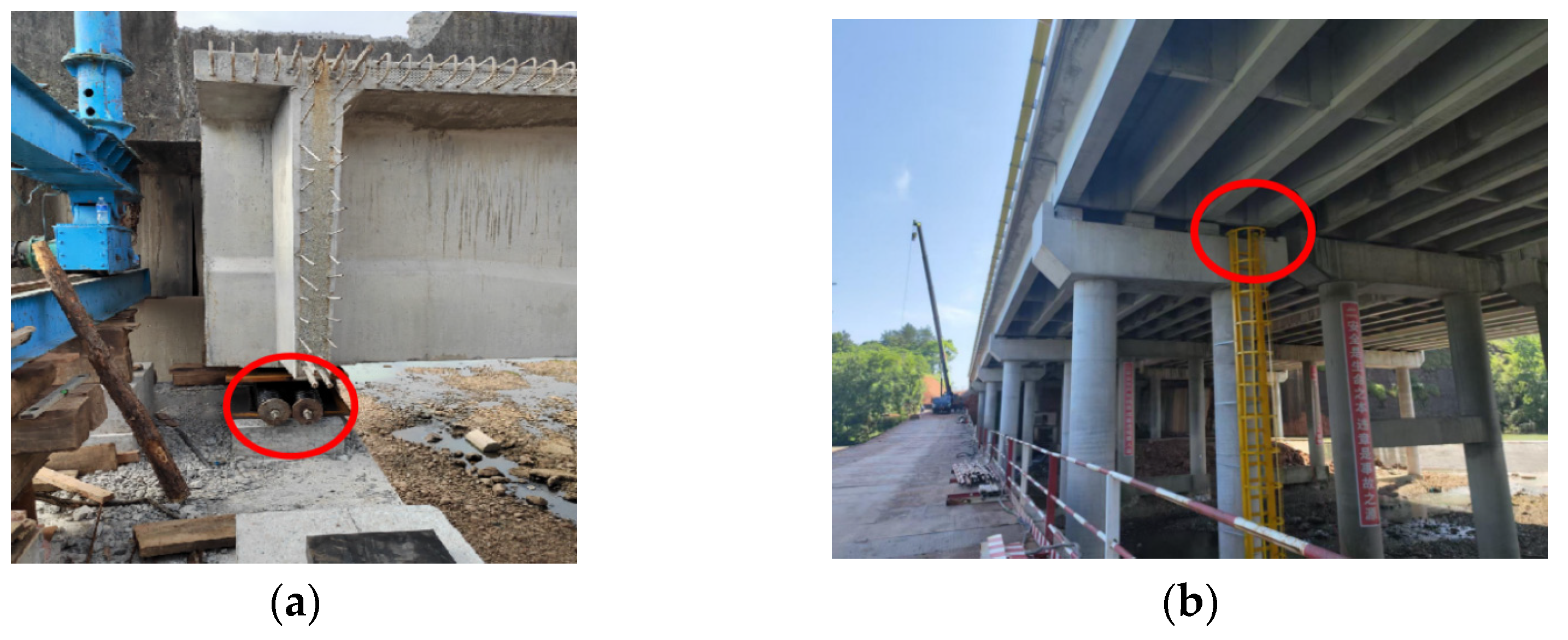
This section is based on the expansion and reconstruction project of the Zhonghe Bridge located on Liwen Expressway in Yushan County, Shangrao City. Taking the Lidong Project as a case study, the existing straight bridge was widened through structural integration, with most of the original old bridge retained to save labor and material resources. For the existing structure, a method was employed involving widening two lanes on each side, as illustrated in
Figure 8.
4.2.1. Boundary Displacement Condition Setup
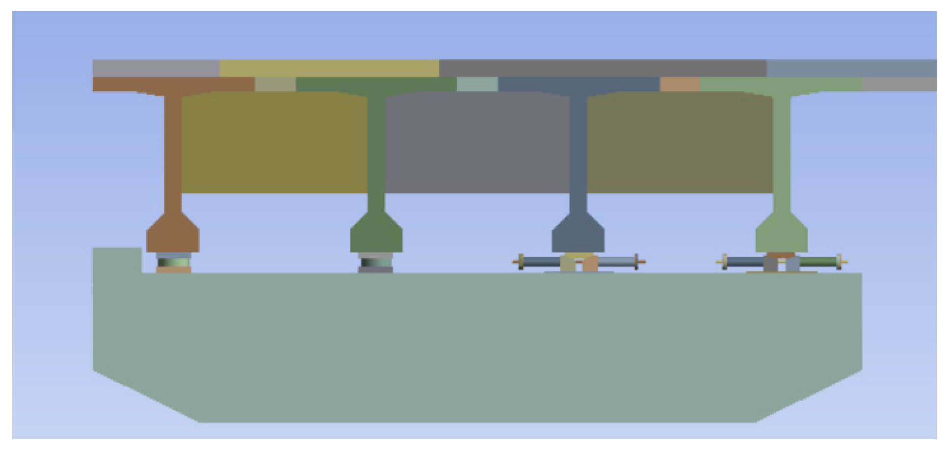
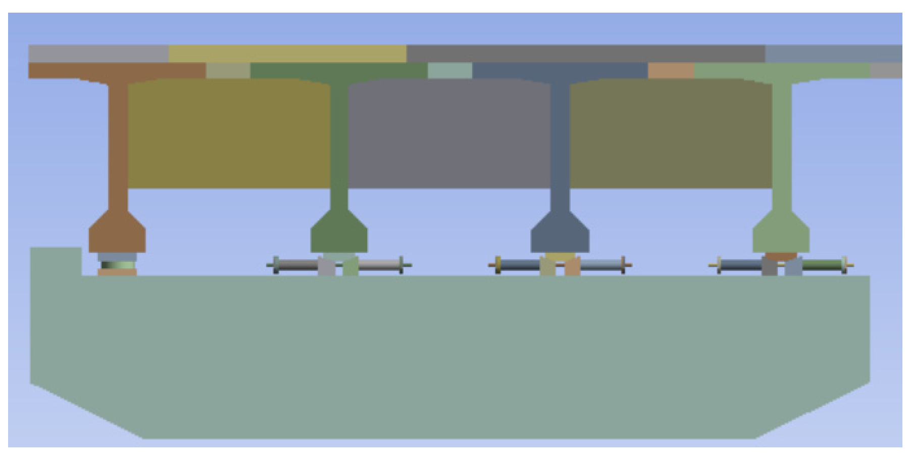
Considering the effect of the adaptive rebound displacement compensation device, this device is only placed at the lower part of the bridge near the expansion joint to replace rubber bearings. The overall model consists of two spans; therefore, three devices are installed along the longitudinal direction of the bridge to observe and monitor whether there is any impact from or comparison with a structure without an adaptive rebound displacement compensation device on top structural settlement caused by pier settlement in new bridges. The bottom steel plate connecting these devices is horizontally positioned on abutments, aligned with other rubber bearing locations as shown in
Figure 9.
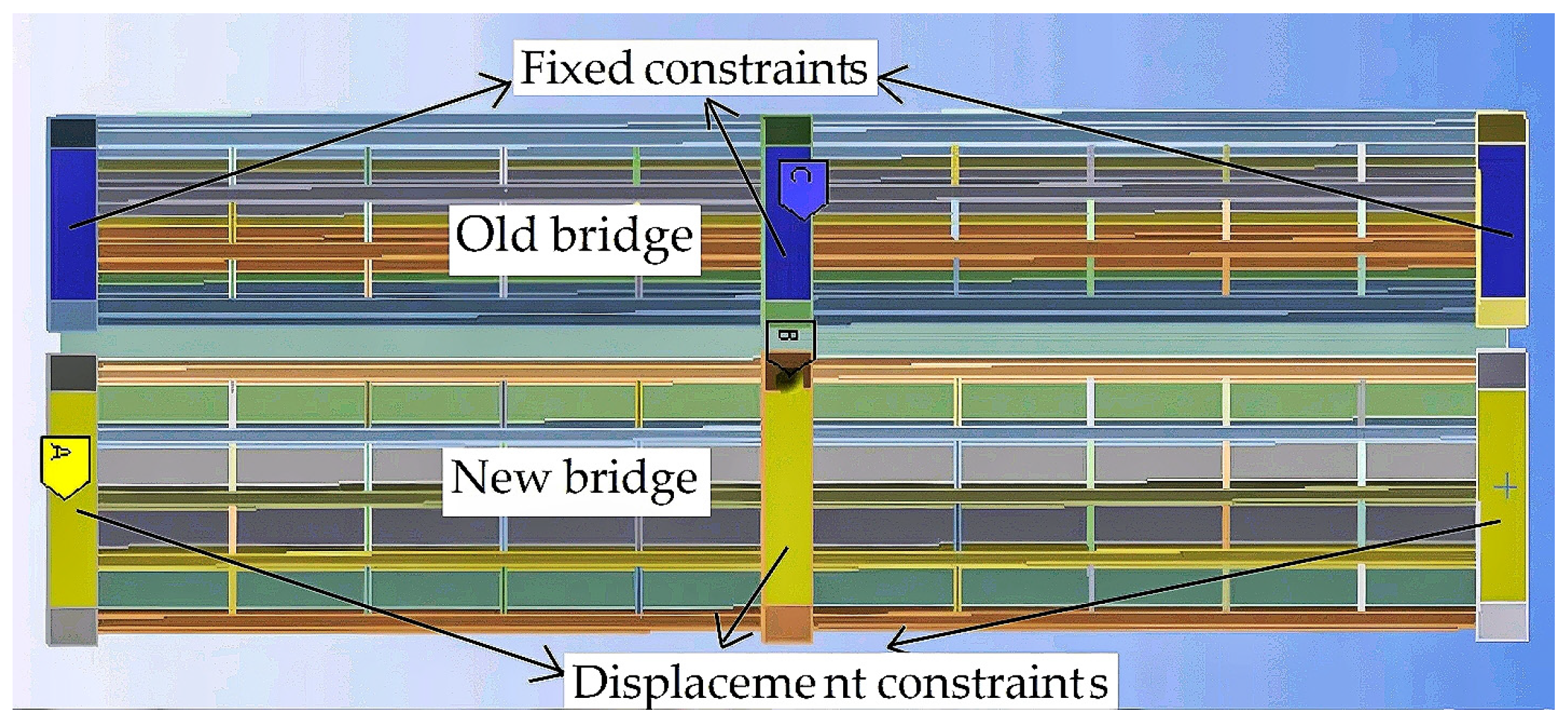
The T-beams are connected via shear webs, and the upper surfaces of each support contact the bottom surface of the T-beam bridge through frictional interfaces, with a coefficient of friction set to 0.3. Displacement constraints in the Y-direction are applied at the base of the new bridge abutments, while fixed boundary conditions are imposed at the old bridge abutments, as shown in
Figure 10. The boundary conditions for the adaptive rebound displacement compensation device are generally consistent with those described in the previous subsection; however, the lower surface of the steel plate is modified to be bonded directly to the abutment contact interface.
The bottom surface of the abutment for the old bridge is fixed with constraints. For the new bridge, five displacement conditions are applied to the bottom surface of the abutment, specified as vertical downward displacements of 1 mm, 2 mm, 3 mm, 4 mm, and 5 mm. While applying these displacements, the upper cap is constrained in both X and Z directions to prevent outward displacement of its two trapezoidal plates caused by the self-weight of the bridge; only Y-direction displacement is allowed to ensure the accuracy of simulation results. Similarly, the X and Z displacements of the nuts are constrained at both ends to ensure that the nuts, washers, and springs at both ends can move downward simultaneously as the piers settle. Additionally, the concept of load steps is incorporated into the analysis, divided into two steps. In the first step, a pre-tightening force is applied to the springs and then locked; during the gradual sinking of the pier foundation, their bolt forces decrease gradually until reaching a fixed value. In the second step, vertical downward displacements ranging from 1 mm to 5 mm are imposed on the piers of the new bridge section; as these piers settle gradually with their foundations, their bolt forces also decrease progressively until stabilizing at a fixed value.
4.2.2. Finite Element Analysis of Overall Structural Results
The displacements of the upper structure of the bridge were analyzed under five different loading conditions, corresponding to pier settlements ranging from 1 mm to 5 mm. These results were then compared with the simulation outcomes of a bridge without the devices, as summarized in
Table 2.
Based on the comparison results in
Table 2, it can be observed that when no adaptive device is installed, the initial displacement of the deck is nearly zero. Under this condition, the upper structure of the bridge can be considered approximately as a rigid body; thus, the settlement of the piers and the sinking of the deck should be essentially consistent. The finite element analysis shows that when pier settlement reaches 5 mm, the corresponding deck settlement displacement is about 4.945 mm, with only a slight difference between them. In contrast, with an adaptive rebound displacement compensation device in place, the initial displacement of the deck remains at 0 mm—indicating negligible downward movement. This occurs because pre-tensioned springs exert an upward force on top cover plates to prevent initial displacements caused by self-weight-induced sinking of the upper structure. Finite element results indicate that at a pier settlement of 5 mm, the deck sinks approximately 2.436 mm—a significant reduction compared to scenarios without such devices. Overall, incorporating an adaptive rebound displacement compensation device markedly decreases deck settlement under similar loading conditions.
The comparison of the relative displacement reduction between the simulation with the standalone device (
Table 1) and that of the entire bridge structure (
Table 2) shows consistent core findings: despite differences in absolute values due to variations in model boundary conditions (force coupling between the standalone device and overall structural model), both results clearly indicate that the device significantly reduces displacements. Additionally, in both models, a linear increase in displacement is observed when devices are present, while near-rigid transmission occurs without devices—demonstrating complete consistency. These observations suggest that the results are not influenced by model scale and exhibit strong robustness.
Additionally, average principal stresses at expansion joints between old bridges and new bridges were extracted from these overall calculations both with and without these devices and are presented in
Table 3 and
Table 4.
The results shown in
Table 3 and
Table 4 indicate that, at both the old bridge and new bridge expansion joints, the average normal stresses with an adaptive rebound displacement compensation device are significantly lower than those without such a device. Additionally, the absolute values of stress increase as the pier settlement displacement grows. Under identical settlement displacements, the rate of increase in absolute stress at the expansion joints is faster when no adaptive rebound displacement compensation device is used. When the pier settlement reaches 5 mm, the compressive stress at the old bridge’s expansion joint increases from −2.01 MPa to −3.36 MPa, while the tensile stress at the new bridge’s expansion joint rises from 2.94 MPa to 6.13 MPa. The differences are particularly pronounced, indicating that an adaptive rebound displacement compensation device can effectively reduce stress concentrations at both old and new bridges’ expansion joints. Moreover, larger displacements result in more significant stress mitigation effects.
4.3. Effect of the Number of Adaptive Devices on Stress at Expansion Joints and Settlement Compensation of the Superstructure
This subsection focuses on exploring the influence mechanism of varying quantities of adaptive devices installed at bearing supports in widened bridges, specifically their effect on stress variations at expansion joints and the relationship between device quantity and superstructure settlement compensation when new bridge piers undergo subsidence. Through their unique adjustment functions, these devices can dynamically respond to bridge loads, effectively disperse and control stress concentrations, thereby enhancing overall bridge performance. The study aims to systematically investigate through numerical calculations how the number of adaptive devices relates to stress responses in expansion joint structures and superstructure settlement compensation, providing valuable insights for optimized widened bridge design.
4.3.1. Establishment of Finite Element Model for New Bridge and Boundary Conditions
To ensure that the devices achieve the same effect as in
Section 4.2.2, boundary conditions and coordinate settings are kept consistent with those in
Section 4.2.1. No external loads are applied; only the self-weight of the bridge and settlements ranging from 1 mm to 4 mm at each new pier are considered. Since relevant data for the case where one device is installed at each end of the new bridge has already been obtained in
Section 4.2, this subsection only performs finite element analyses for cases where two or three devices are installed at each end separately. Using SolidWorks software 2022, finite element solid models with two and three devices, respectively, were established, as shown in
Figure 11 and
Figure 12 below.
4.3.2. Finite Element Results for Overall Structure Under Different Device Quantities
As indicated in
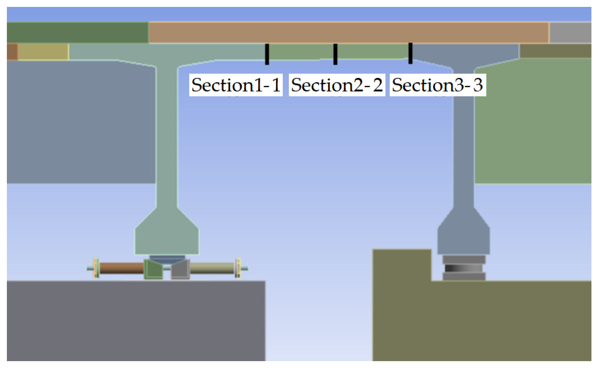
Section 4.2.2, when the new bridge piers undergo settlement, the maximum tensile stress at the expansion joint occurs at the bottom of the connection surface with the new bridge, while the maximum compressive stress occurs at the bottom of the connection surface with the old bridge. The control sections are selected consistently; stresses at the bottoms of sections 1-1, 2-2, and 3-3 are extracted for comparative analysis under conditions with and without adaptive devices. The section positions are shown in
Figure 13.
This subsection analyzes the stress variation in the expansion joint structure and its compensating effect on the settlement displacement of the superstructure when the new bridge piers undergo settlements ranging from 1 mm to 4 mm, with and without adaptive devices. The results are presented in
Table 5 and
Table 6.
From
Table 5, it can be observed that the maximum tensile and compressive stresses at the expansion joint decrease as the number of adaptive devices increases—from no adaptive device to three adaptive devices installed at each end. Moreover, with an increasing number of adaptive devices, the reduction in positive stress becomes more significant. For example, when the new bridge piers settle by 4 mm and two adaptive devices are installed at each end, the maximum tensile stress decreases from 2.556 MPa to 1.737 MPa, a reduction of approximately 32%. The stresses at the other two control sections also show a certain degree of decrease; this is because during pier settlement, springs exert upward forces that generate vertical displacement in the devices to compensate for superstructure settlement. This further reduces loss of load capacity in the upper structure and consequently diminishes stresses at the expansion joints.
From
Table 6, it can be seen that increasing the number of adaptive devices significantly reduces the displacement of the bridge superstructure. For example, under a settlement condition of 4 mm for the new piers, the vertical downward displacement without any adaptive device is 11.410 mm. When one, two, and three adaptive devices are installed at each end, respectively, these displacements decrease to 9.118 mm, 8.421 mm, and 8.254 mm—corresponding to reductions of approximately 20.1%, 26.2%, and 27.7%. This indicates that increasing the number of adaptive devices enhances their effectiveness in compensating for upper structure displacements.
5. Experimental Study of the Adaptive Rebound Displacement Compensation Device
Through the theoretical derivation and finite element analysis conducted in
Section 2,
Section 3 and
Section 4 regarding the working principle of the adaptive rebound displacement compensation device, it was found that when the new bridge piers settle, this device can reduce the loss of load capacity in the piers, thereby decreasing bending positive stresses at expansion joints. To further validate the effectiveness of this device, experiments were carried out on the adaptive devices to obtain pier load capacities before and after settlement. These experimental results were compared with theoretical solutions to verify their accuracy and assess the feasibility of using such devices in engineering applications—providing strong evidence for promoting widespread adoption.
5.1. Experiment Equipment and Specimen Design
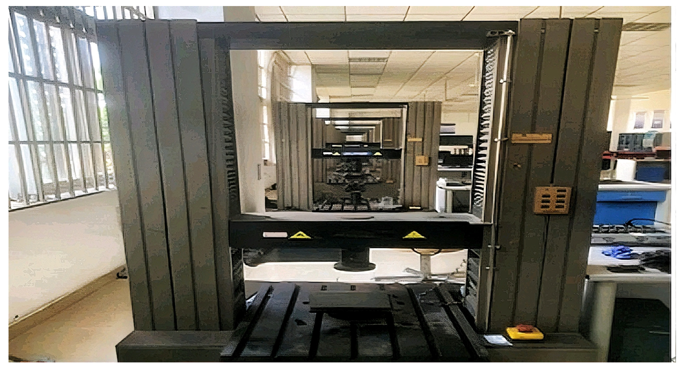
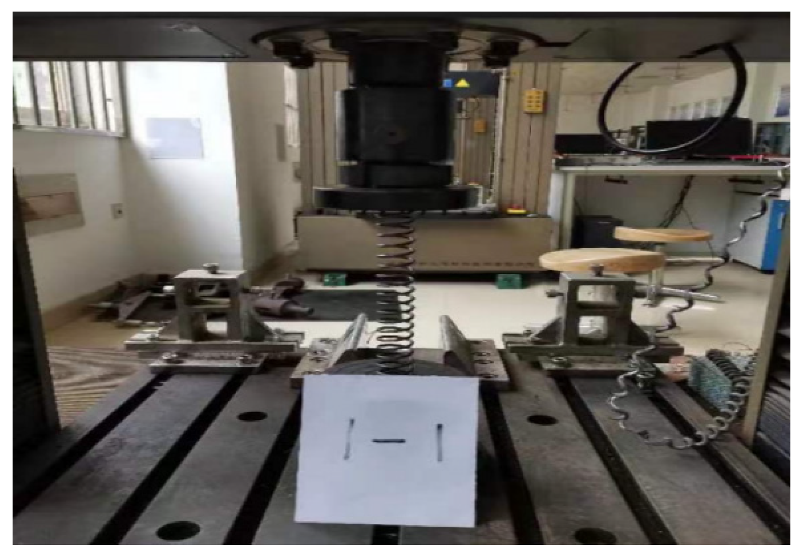
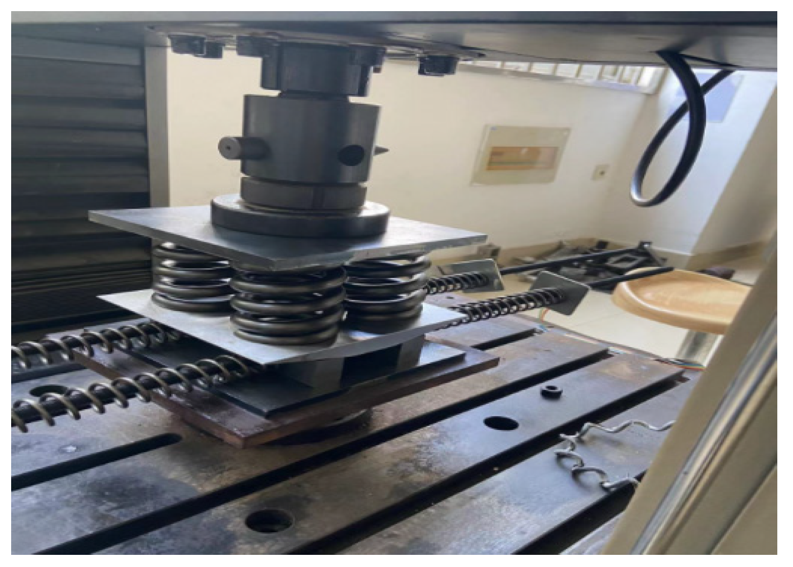
The experiment employed a computer-controlled electro-mechanical universal testing machine (Shanghai Lishi Science Instruments Co., Ltd., Shanghai, China) to perform loading tests on the adaptive rebound displacement compensation device, as shown in
Figure 14. The test machine features a dual-space structure capable of conducting both tension and compression tests. Load is applied via hydraulic pressure onto an intermediate crossbeam, controlling its movement to realize loading action. The lower space beneath the beam serves as a compression zone with a semi-circular base structure ensuring axial compression during tests. The upper space functions as a tension zone; specimens are fixed by upper and lower clamps aligned vertically to ensure axial tension during tensile testing. This equipment provides highly precise load control with errors below 0.5%, meeting various testing accuracy requirements; it also allows setting loading steps and hold times for observing phenomena during experiments. A fully digital high-response measurement system based on DSP technology transmits data via USB communication at high speed (12 Mb/s).
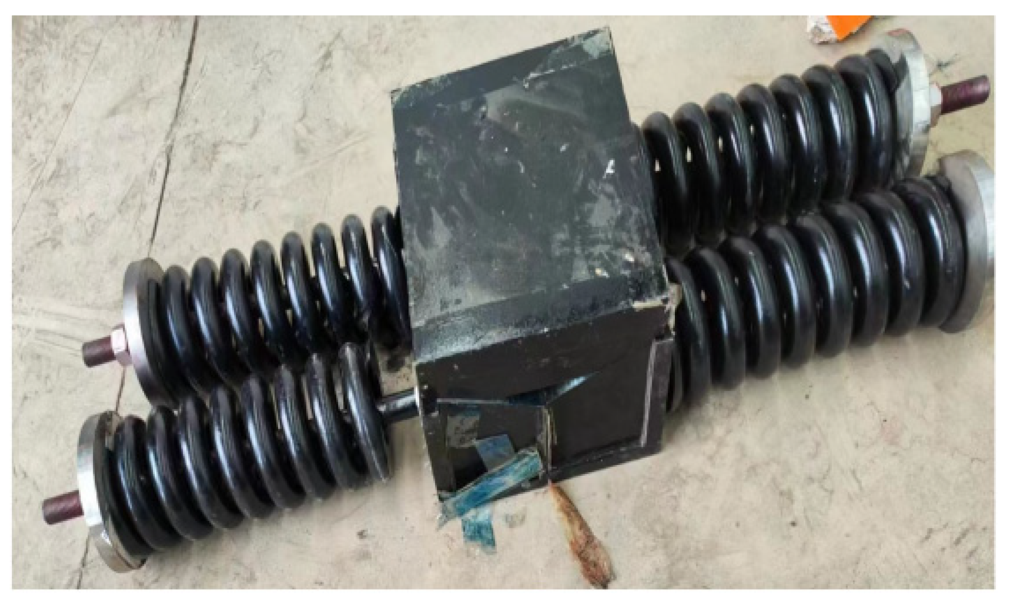
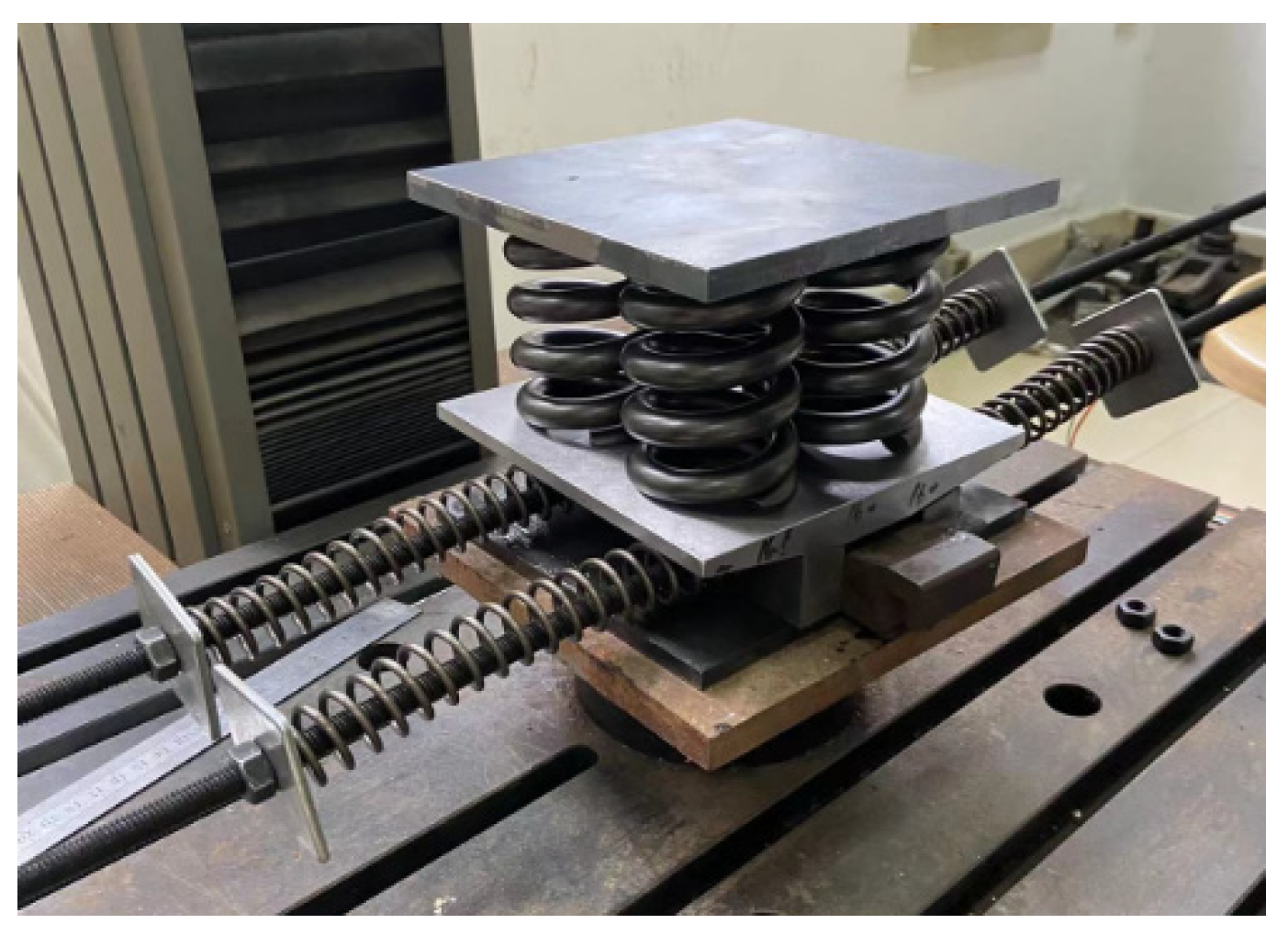
The overall specimen model is shown in
Figure 15. This experiment employed two M10 screws (grade 10.9), each approximately 1 m in length; four galvanized square washers measuring 10 mm × 50 mm × 3 mm (inner hole diameter × side length × thickness); four high-strength M10 nuts (grade 10.9); four small springs with dimensions of 3 mm in wire diameter, 25 mm in coil diameter, and a length of 200 mm, each having about twenty turns; four large springs measuring 12 mm in wire diameter, 60 mm in coil diameter, and an overall length of 80 mm, each with approximately four turns; two wedge-shaped sliders inclined at a horizontal angle of 15°; one wedge-shaped body with a horizontal inclination angle of 15°; along with a rectangular top plate and a rectangular bottom plate. The bottom plate is positioned at the lowest point, upon which the wedge slider is placed. The wedge-shaped body is tightly attached to its upper surface on the wedge slider. Four large springs are located on top of the wedge-shaped body’s upper surface. The top plate sits above all components. Two screws pass through holes on opposite sides of the wedge slider assembly; four small springs are mounted around these screws between washers and nuts at their ends.
5.2. Experiment Procedure
The experiment is divided into five steps:
Step 1: First, determine the stiffness coefficients of the four small springs. The four small springs are numbered 1, 2, 3, and 4. Axial force loading tests are conducted on each spring using a control program that applies force until reaching a final value of 150 N. Each spring undergoes six repeated tests; for example, the loading process for Spring No. 1 is shown in
Figure 16.
Step 2: Determine the equivalent stiffness coefficient of the upper structure of the wedge-shaped body (the four large springs and rectangular top plate). An axial force loading test is performed with a target load of 12,500 N controlled by force application. This procedure is repeated six times under identical conditions.
Step 3: Assemble the specimen: first place the rectangular bottom plate centered on the testing platform; then sequentially stack two wedge sliders, the wedge-shaped body, four large springs, and finally the rectangular top plate from bottom to top. Apply grease to both surfaces—on top of the bottom plate as well as on inclined surfaces of wedges and wedge-shaped bodies—to reduce frictional resistance. Two screws pass through holes in the wedge slider from side to side; by adjusting the nuts, ensure that all four small springs just contact their respective galvanized square washers at both ends while fitting tightly against their mating components (wedge sliders). The overall assembly diagram resembles
Figure 15 in
Section 5.1.
Step 4: Conduct displacement-controlled loading tests on assembled specimens: set an end displacement value for transverse beams downward by 5 mm in your control program. Observe and measure movements of wedge sliders during loading using vernier calipers; record load values and displacements displayed in your program as illustrated in
Figure 17.
Step 5: Perform unloading tests under displacement control: set an upward end displacement value of 5 mm, observe movement via vernier calipers during unloading, and record corresponding load and displacement data as before.
5.3. Experiment Data Analysis
For each set of tests conducted in Steps 1 and 2, the final load values and displacement values were averaged to calculate the stiffness coefficients of the four small springs and the upper structure of the wedge-shaped body, as shown in
Table 7.
During the observation of the loading process in Step 4, it was found that the slider remained stationary during initial pressurization. Only when the applied force reached a certain threshold did the slider begin to slide laterally. This phenomenon is caused by static friction between the contact surfaces of components. In the control program, force data prior to movement initiation were reset to zero; once sliding began, data recording resumed from that point. After multiple tests, the downward displacement of the testing machine was recorded and averaged. It was observed that when the average downward displacement of the upper transverse beam reached approximately 3.98 mm, the slider started moving. Based on the program display, the displacement of the upper transverse beam and the pressure values were obtained: the average compression length of the large spring is 4.97 mm; and the average pressure after slider movement is 1240.26 N. From
Table 7, it can be seen that each small spring has an average stiffness coefficient of about 7.54 N/mm. Using a vernier caliper to measure slide displacement, an average shift of 20.97 mm was recorded for each side’s small-spring compression—that is, both sides’ small springs were compressed by this amount during operation.
According to the theoretical derivation in
Section 2, if the pressure on the upper part of the wedge-shaped slider is denoted as
, and the total horizontal thrust of the four small springs is
, then the ratio
between the springs’ horizontal thrust and vertical pressure can be expressed as
The average pressure after slider movement obtained from the program is 1240.26 N, which corresponds to in Equation (1). Using the mean stiffness coefficient and average compression of the four small springs, the total horizontal thrust of these springs is calculated as 632.46 N, with an inclination angle . By substituting these values into Equation (20), the friction coefficient is back-calculated as 0.115.
In the unloading test of Step 5, which is similar to Step 4, the slider initially remains stationary. Only when the program indicates that the average upward displacement of the upper transverse beam reaches 4.02 mm does the slider begin to slide inward under spring thrust. From the onset of sliding until it stops, the average upward displacement of the beam is 0.98 mm, and at this point, a pressure reading from the online program shows an average value of 1041.66 N. This stage simulates conditions corresponding to the settlement of a new bridge pier; thus, the total rebound amount of the upper large springs can be considered equivalent to the settlement volume of a new bridge pier. At this moment, this averaged pressure value, 1041.66 N, represents, under experimental conditions, the loss of force () acting on a bridge pier during sinking while influenced by our adaptive recoil displacement compensation device; hence, it serves as an experimental estimate for .
Substituting , , N/mm, N/mm, and d = 5 mm into Equation (15), the calculated value of is 955.12 N. This means that when the new bridge pier sinks by 5 mm, the theoretical loss of force value of the pier is 955.12 N, while the experimental value is 1041.66 N. The difference between them is approximately 8.47%. This discrepancy arises due to measurement errors in the experiment itself and phenomena such as eccentric loading during axial compression; additionally, this micro-scale test cannot fully replicate the effects of our adaptive recoil displacement compensation device on a real bridge structure. Therefore, this error falls within an acceptable range. The test validates the effectiveness of the adaptive recoil displacement compensation device and provides strong evidence for its potential application in engineering practice.
7. Conclusions
This study addresses the impact of differential settlement between old and new bridge foundations on structural performance in straight bridge widening projects, proposing an “Adaptive Rebound Displacement Compensation Device”. The study demonstrates that this device can effectively and dynamically adjust bridge deck settlement, significantly reducing bending stresses in the joint areas, thereby enhancing the safety and durability of bridges and providing a new solution for bridge widening projects.
In the theoretical analysis section, we explored the relationship between bridge deck settlement displacement and structural loss of load-bearing capacity, as well as the influence of various parameters on this relationship. By deriving relevant theoretical expressions, we clarified the interrelationship between the loss of load-bearing capacity in the superstructure of the bridge and factors such as the amount of pier settlement, the stiffness of the device, the friction coefficient, and the angle of the L-shaped baffle. These expressions reveal how to optimize bridge deck displacement and structural loss of load-bearing capacity by adjusting the design parameters of the device under different working conditions, thereby reducing stress in the joint areas. This theoretical framework provides a scientific basis for the design and practical application of the device, ensuring that the expected results can be achieved in addressing structural issues caused by pier settlement.
Through finite element simulation and experimental research, the effectiveness of the adaptive rebound displacement compensation device in controlling bridge deck settlement has been validated. The results indicate that with the adaptive device installed, the displacement of the bridge deck is significantly lower than in the absence of such a device. Moreover, this device can effectively limit the amount of deck settlement to between 10% and 20% of the pier settlement, while also markedly reducing stress concentration at expansion joints. This enhances both structural safety and durability. Additionally, increasing the number of devices further improves their compensatory performance, which helps reduce deformation and cracking risks in the superstructure.
In practical engineering applications, the “Adaptive Rebound Displacement Compensation Device” has been successfully installed in the widening project of new and old bridges on a highway in Jiangxi Province. Finite element simulation data from the engineering application were incorporated into theoretical calculations, demonstrating that the device can effectively reduce deck settlement and bearing uplift during pier subsidence, with reductions of approximately 16.5% compared to scenarios without the device. This significantly alleviates additional structural stresses. At the conclusion of the project, instrumentation was installed to monitor pier settlement data; however, the final displacement measurements are expected to require three to four years for accurate assessment.
In summary, the research findings of this paper provide important theoretical support and practical references for the design and construction of bridge widening projects. Future research can further explore the optimization design of adaptive bearing devices, incorporating new materials and intelligent monitoring technologies to enhance their performance and adaptability.