Abstract
To investigate the complex interaction in multi-structure systems, this study establishes a refined 3D numerical model based on a transportation hub project in Tianjin to analyze the asymmetric coupling deformation mechanism of a deep excavation adjacent to a shared-wall metro station and elevated bridge piles. This study highlights the transition from soil-mediated interaction mechanisms to those dominated by structures under shared-wall constraints. Results show that the existing station acts as a high-stiffness boundary, effectively suppressing lateral-wall deflection and basal heave on the proximal side. A critical finding is the reversal of the station’s deformation mode: while stations with a soil buffer typically tilt toward the excavation, the shared-wall station exhibits a clockwise rotation away from the excavation; this phenomenon is driven by excavation-induced basal rebound directly transferred through the common diaphragm wall. Furthermore, the station exerts a significant “shielding effect” on adjacent bridge piles, shifting their maximum lateral displacement from the pile head to the toe and reducing overall deformation. Parametric analyses reveal that optimizing shared-wall thickness is more effective for controlling lateral deformation, whereas increasing wall depth primarily mediates vertical heave. This study concludes that, for shared-wall systems, design priorities must shift from settlement control to anti-heave measures, and pile monitoring should extend to the deeper critical zones identified in this study.
1. Introduction
With the rapid advancement of urbanization and the increasing density of urban infrastructure, deep excavations have become a core component of underground space development and are widely applied in the construction of metro stations, commercial complexes, and transportation hubs [1,2,3]. The stability of such underground developments is fundamentally governed by complex mechanical failure, nonlinear evolution, and energy transformation mechanisms within the surrounding geological environments [4,5]. In areas with dense underground structures, newly excavated deep excavations must not only ensure their own structural safety [6] but also protect adjacent existing structures, such as underground stations [7] and piles [8], from excessive deformation. Under spatial constraints, the unloading response induced by excavation can transfer ground deformation to nearby structures, resulting in coupling deformation [9]. Specifically, excavations may lead to excessive deformation of adjacent underground stations [10,11,12], potentially causing structural damage and even threatening operational safety. Meanwhile, under asymmetric loading and stratigraphic conditions, the retaining structures of deep excavations exhibit significant asymmetries in soil pressures, deformation patterns, and internal force distributions, which, in severe cases, may even result in instability or collapse.
To address the deformation of adjacent metro stations induced by excavation, extensive studies have been conducted using field monitoring [13,14,15], numerical simulations [16,17,18], and physical model tests [19]. These investigations have explored the key influencing factors, such as excavation depth and distance [16]; typical structural deformation patterns, including station tilt orientated toward the excavation [20]; and the “barrier” or “shielding” effects of existing structures on excavation-induced deformation [18,21]. They have also verified the effectiveness of various control measures, including staged excavation [22] and cross-wall installation [14]. However, most of these studies have focused on cases where a soil buffer exists between the excavation and the existing station, whereby deformation is primarily transmitted through the intervening soil. In contrast, when the excavation and the existing subway station share a common wall, the unloading induced by excavation is no longer primarily transferred through the soil; instead, it acts directly on the station’s structure or the shared retaining wall [23]. In recent years, scholars have begun exploring this direct coupling mechanism from several dimensions. Regarding the mechanical interaction, Li et al. [24,25] identified that the interaction mechanism shifts from soil-mediated deformation transfer to a direct mechanical response governed by structural stiffness differences between the station frame and the retaining wall. From the perspective of spatial deformation patterns, Zhen et al. [7] and Yang et al. [23] quantitatively analyzed the complex heave and torsional responses of subway stations under zero-distance conditions through numerical methods, emphasizing the dominant role of base rebound. Furthermore, the sensitivity of the coupled system to construction parameters, such as the excavation sequence and zoned construction, was examined through field observations and simulations [26,27]. Nevertheless, these studies remain largely limited to phenomenological analyses of specific engineering cases or single-station–excavation interactions. In complex urban environments, deep excavations often involve asymmetric structural layouts and coexist with other sensitive structures, such as elevated bridge piles. A systematic understanding of the coupled deformation modes and internal force transfer mechanisms among excavations, shared-wall stations, and adjacent piles under such asymmetric constraints has yet to be fully established. The underlying mechanisms of this three-party coupling therefore require further in-depth investigation.
Extensive research has been conducted on excavation behavior under asymmetric conditions [28,29,30]. In the existing literature, studies on the asymmetric behavior of excavations can be generally categorized into three main types based on the origin of the asymmetry: (1) asymmetric external loading, (2) geometric or structural asymmetry, and (3) geological or environmental asymmetry. Most studies have focused on asymmetric external loading, such as nearby embankments, traffic loads, or unbalanced surface surcharges [28,29,31]. Several researchers have examined geometric or structural asymmetry, which depends on the design of irregular retaining systems [32] and the optimization of supporting structures [33]. Additionally, asymmetric geological or environmental conditions, such as stratigraphic heterogeneity or adjacent river channels [34], have also been explored. However, the asymmetry considered in these studies primarily originates from external factors or stratigraphic heterogeneity. When a new excavation is adjacent to an existing underground structure, such as a metro station, the asymmetry instead arises from spatial constraints imposed by the existing structure and the coupling mechanical interaction during construction. Currently, the mechanisms of asymmetric deformation and internal force transfer induced by such multi-structure coupling constraints, especially those involving the complex interaction among excavations, shared-wall stations, and adjacent bridge piles, have yet to be systematically elucidated and therefore warrant in-depth investigation.
To achieve the objectives mentioned above, this study, which is based on the Tianjin Binhai International Airport Integrated Transportation Hub Project, establishes a refined three-dimensional numerical model of an excavation–existing metro station–pile foundation system using PLAXIS 3D 2024. This model systematically investigates (1) the asymmetric deformation response of the excavation under shared-wall constraints, (2) the deformation patterns of the existing shared-wall metro station induced by excavation, and (3) the coupling deformation mechanism of adjacent pile foundations while considering the influence of existing structures. The findings of this study aim to advance the mechanistic understanding of coupling effects in deep excavations within densely built environments and to provide theoretical guidance and practical references for the design and safety control of similar complex engineering projects.
2. Engineering Overview
2.1. Project Overview
This study is based on the Tianjin Binhai International Airport Integrated Transportation Hub Project, a large-scale integrated hub that encompasses multiple components, including Terminal 3, the Jingbin Railway, Metro Line Z2, Metro Line M2, and associated bus and parking facilities. The spatial relationships among these subsystems are extremely compact, as illustrated in Figure 1. For example, the intersection nodes of several rail transit lines are located directly beneath the main structure of Terminal 3. The project is categorized as a super-large excavation and involves simultaneous operations by multiple construction entities. Thus, it is challenging to achieve complete synchronization among the various parties, and the substantial unloading effects during excavation pose significant threats to the normal operation and structural safety of adjacent existing stations and the terminal building. Therefore, investigating the deep-excavation-induced deformation mechanism of existing structures is of great significance for ensuring the overall construction safety of the hub, as well as the safety status of adjacent metro stations and the service performance of metro tunnels.
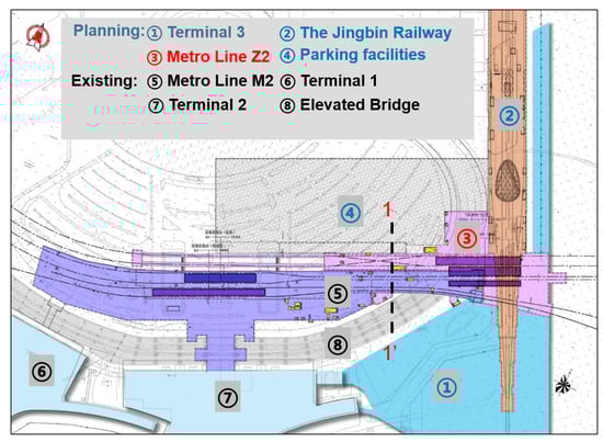
Figure 1.
Project plan schematic.
The present study investigates the interaction between the Z2 Line excavation and adjacent existing structures, specifically the M2 Line metro station and the elevated bridge pile foundations. The T3 station on the Z2 Line is a two-level underground island station with a platform width of 13 m and a length of 373.457 m. The corresponding excavation is 400 m long, with a width varying from 28 m to 110 m and a depth ranging between 22.2 m and 24 m. Crucially, the excavation lies in close proximity to multiple existing underground structures, including the M2 Line station and the airport’s elevated bridge foundations, as illustrated in Figure 1. Specifically, the existing T3 Terminal Station on the M2 Line is a two-level underground side-platform station that features platform widths of 10.5 m and 14.75 m and a total length of 393.257 m. The elevated bridge features a cast-in-place box girder system, with pile foundations located approximately 42 m from the Z2 Line excavation. This complex environment induces pronounced asymmetry in the loading and deformation behavior of the excavation, further increasing construction difficulty and risks. To address these stringent environmental constraints and deformation control requirements, the Z2 Line excavation adopted the top-down method, which is supported by a retaining system comprising diaphragm walls and three levels of horizontal slabs. A representative section, denoted as profile 1-1′ in the standard segment of the Z2 Line excavation, is shown in Figure 2.
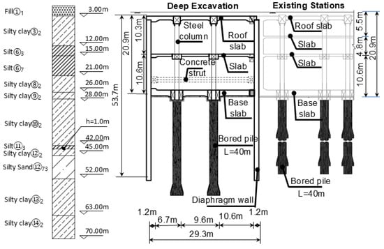
Figure 2.
“1-1′” section view of deep excavation adjacent to existing underground structure.
2.2. Environmental Overview of the Site
According to a geological investigation report, the site’s stratigraphy, from top to bottom, comprises artificial Holocene fill, recent deposits strata, marine deposits of Layers I to IV, and continental deposits of Layers II to VI. The predominant soil types include fill, silty clay, clay, silt, and silty sand. The spatial distribution of these strata and the key physical and mechanical parameters of each soil layer, including thickness, unit weight, and cohesion, are detailed in Table 1. Among these soils, the clay layer exhibits considerable thickness, high compressibility, and pronounced sensitivity, rendering it particularly susceptible to strength degradation caused by nearby construction disturbances in the surrounding area.

Table 1.
Physical and mechanical properties of soil layers.
The groundwater level at the site is generally high, and medium-permeability layers such as silt and silty sand are widely distributed, resulting in complex hydrogeological conditions. Shallow groundwater is dominated by quaternary phreatic water, with a burial depth ranging from 0.5 to 2.6 m, and is primarily found within the artificial fill and the silt of Marine Layer I. Recharge is predominantly from precipitation and surface water infiltration. In the deeper strata, the first to fourth confined aquifers are developed and hosted by the silty and sandy layers of the corresponding continental and marine deposits, with stable hydraulic heads ranging from −1.00 to −5.00 m. Due to the complex distribution of confined aquifers, the high groundwater level, and the limited thickness of weakly permeable layers, the site is subject to a high risk of interlayer seepage. These conditions substantially increase the likelihood of groundwater inflow and dewatering-induced deformation during excavation, thereby imposing stringent requirements on safety control for excavation construction.
2.3. Geometric Model Parameters and Boundary Conditions
A three-dimensional coupled deformation analysis model comprising the soil, the Z2 Line excavation, existing M2 Line structures, and elevated bridge foundations was developed using PLAXIS 3D. Figure 3 illustrates the model’s schematic, where bridge foundation locations were derived from the site plan. The coordinate system aligns the X-axis along the Z2 Line’s longitudinal direction, with the Y-axis and Z-axis perpendicular and vertical to it, respectively. To mitigate boundary effects, the model comprehensively considered the excavation’s dimensions, depth, and the proximity of adjacent underground structures. According to Saint-Venant’s principle and engineering practice, the lateral and vertical influence zones are typically 3–5 and 2–4 times the excavation depth [5], respectively. Accordingly, the model dimensions were set to 30 m, 200 m, and 70 m in the X, Y, and Z directions. The soil domain was discretized using 10-node tetrahedral elements, ensuring accurate simulations of complex geological interfaces.
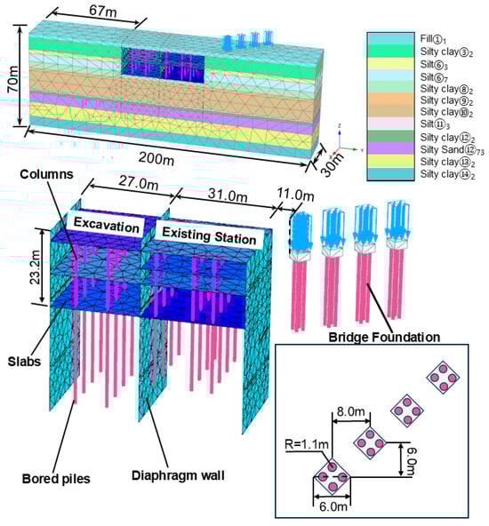
Figure 3.
Finite element model and mesh division under basic conditions.
2.4. Calculation Parameters
To accurately simulate the deformation responses of the retaining structure, the shared-wall existing station, and the elevated bridge foundation, the HS-Small constitutive model was adopted for the soil. This model effectively captures the nonlinear deformation characteristics of soils during excavation-induced unloading and is thus well-suited for simulating their mechanical behavior under complex geological conditions. The physical and mechanical parameters of the soil layers were determined based on borehole sampling and laboratory testing results presented in the geological investigation report and supplemented by engineering experience from the Tianjin region. To simplify the model, soil layers with similar properties were combined. The detailed parameters, including unit weight, cohesion, internal friction angle, and elastic modulus, are summarized in Table 1.
In the numerical simulation, the retaining structure of the excavation is thought to be retained within the elastic range throughout the construction process. The types of structural elements and the corresponding elastic moduli used in the model are summarized in Table 2, where plate elements were assigned to the retaining walls and beam elements were used for the struts. The unit weight of all concrete structures was uniformly taken as 25 kN/m3, and a Poisson’s ratio of 0.2 was adopted for all structural elements. These values follow commonly accepted engineering practices and are therefore not listed separately in Table 2.
Table 2.
Structural element parameters of finite element model.
2.5. Construction Procedures
Following mesh generation, the construction sequence was defined to simulate the top-down excavation method adopted for this project. The initial stress field was first generated as Stage 1 using the K0 procedure in PLAXIS 3D, a method that computes the initial geostatic stress state for subsequent analyses. In Stage 2, the existing metro station and bridge foundation structures were activated. To eliminate artificial deformations induced by the generation of these structures, displacements were reset to zero in Stage 3, which is prior to the commencement of the excavation simulation. A total of thirteen calculation phases were defined in the model, with detailed steps summarized in Table 3. Here, “E-1” denotes the first excavation stage, and “S-1” represents the installation of the first slab, with subsequent stages following the same naming convention.
Table 3.
Construction sequence.
2.6. Model Validation
A three-dimensional finite element model was developed based on the excavation project of an elevated bridge (Figure 4a) [35] while following the actual construction sequence. To verify the reliability and accuracy of the finite element simulation method and software implementation, the computed horizontal displacements of the diaphragm wall were compared with the field measurements. As shown in Figure 4b, the numerical results exhibit good agreement with the observed displacement patterns, including both the maximum horizontal displacement and the overall deformation profile. Notably, the maximum diaphragm wall displacement obtained from the simulation is 12.11 mm, while the measured value is 10.96 mm, yielding a discrepancy of only 10.5%. The consistency between the numerical predictions and field data indicates that the finite element simulation method was reliable and that the accuracy of the modeling approach in this study was acceptable.
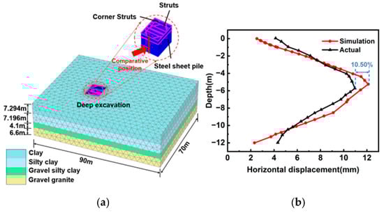
Figure 4.
Validation of numerical analysis: (a) Three-dimensional finite element model (b) Comparison of diaphragm wall horizontal displacement with measured values.
3. Simulation Cases and Result Analysis
Based on the aforementioned framework, this study employs the three-dimensional finite element method to conduct parametric analyses of the spacing D between the excavation and metro station, along with the shared-wall thickness d and embedded depth H. In total, 17 numerical models were established and computed, with specific calculation cases summarized in Table 4.
Table 4.
Calculation condition.
3.1. Asymmetric Deformation of the Excavation Under the “Shared Wall” Constraint
Figure 5 illustrates that the horizontal distance between the excavation and the existing station exerts a significant influence on the surrounding soil deformation, and the deformation pattern presents three typical modes as the spacing varies. When D = 0 (shared-wall condition) (Figure 5a), the absence of soil between the excavation and the existing station results in a distinct deformation pattern: the soil heave at the bottom of the excavation on the side away from the existing station is markedly greater than that on the existing station’s side, and soil displacement adjacent to the diaphragm wall on the far side also substantially exceeds that near the existing station. As the horizontal spacing increases, the deformation tends toward symmetry. At a moderate distance (0.5 He) (Figure 5b), the heave magnitudes at both sides of the excavation bottom become nearly balanced, with only slightly smaller soil deformation observed at the diaphragm wall on the existing station’s side compared with the far side. When the spacing further increases to D = 2.0 He (Figure 5c), the deformation’s distribution reverses. The existing station’s side exhibits noticeably larger soil heave beneath the excavation’s bottom and greater displacement near the diaphragm wall, resembling the deformation pattern of an excavation not unaffected by adjacent structures (Figure 5d). These observations demonstrate that the restraining effect of the existing station on the lateral soil deformation of the excavation progressively diminishes with increasing spacing and becomes negligible beyond a certain distance.
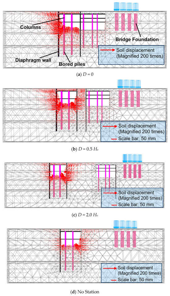
Figure 5.
Vector diagrams of soil deformation under different distances: (a) D = 0, (b) D = 0.5 He, (c) D = 2.0 He, and (d) no station.
The mechanism driving these variations stems from disrupting the initial stress equilibrium triggered by excavation. This disturbance induces a redistribution of internal forces, resulting in lateral deflection of the retaining structure, basal heave, and outward soil movement that propagates away from the excavation. When this propagating displacement encounters the existing station, the structure’s high stiffness and broad cross-section intercept the continuous transmission of soil deformation. Consequently, both the diaphragm wall deformation and basal heave on the existing station’s side are substantially suppressed. Conversely, at a spacing of D = 2.0 He, the existing station’s blocking effect on soil displacement diminishes to a negligible level, and the deformation pattern of the excavation approaches that of a condition without the presence of the existing station.
Figure 6 presents the horizontal deformation of the diaphragm walls on both sides of the excavation at varying spacings, D. The left side denotes the newly constructed diaphragm wall (far side), while the right side represents the wall adjacent to the existing station. Positive values indicate displacement toward the excavation. At a small spacing, the deformation of the wall adjacent to the existing station is significantly smaller due to the station’s spatial constraint. For example, when D = 0 m (shared-wall condition), the maximum horizontal displacement on the adjacent side is only 6.50 mm, whereas the far side reaches 29.67 mm, which is approximately 3.56 times that of the adjacent side. When D = 0.3 He, the deformation on the adjacent side increases to 15.15 mm, while the far side yields 29.80 mm, reducing the difference to approximately 0.96 times. However, as the spacing increases to D = 2.0 He, the constraint effect gradually weakens, and the maximum horizontal displacement on the adjacent side rises to 29.72 mm, surpassing the measurement of 19.86 mm observed on the far side. These results demonstrate that the existing station’s constraint governs the deformation distribution under a small spacing, but this influence decays significantly with distance, eventually reversing the relative deformation pattern between the two walls.
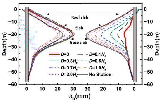
Figure 6.
Lateral deformation of new and existing diaphragm walls under different distances.
Another factor driving the observed deformation and its evolution is the asymmetric arrangement of internal columns. Without station constraints, the maximum horizontal displacement on the side adjacent to the station becomes slightly larger than that on the far side, a pattern entirely opposite to that observed under small-spacing conditions. When the constraint from the existing station becomes weak, the asymmetric structural layout within the excavation becomes the dominant factor influencing deformation. In summary, the spatial distribution of horizontal deformation is not governed by a single mechanism but results from the combined effects of boundary constraints (existing station) and internal structural asymmetry (column arrangement). This interaction exhibits pronounced stage-dependent characteristics as the spacing varies.
Figure 7 illustrates the vertical deformation distribution of the excavation base slab under different spacing distances (D) from the existing station. A horizontal position of 0 m corresponds to the newly constructed diaphragm wall (the side away from the existing station), whereas a distance of 30 m denotes the shared-wall side adjacent to the station. Under the shared-wall condition (D = 0) and close-proximity cases (D = 0.1 He to 0.3 He), the deformation of the base slab on the side adjacent to the existing station is significantly smaller than that on the far side, forming an asymmetric pattern where the near-side deformation is smaller than that of the far side. For example, in the D = 0 case, the maximum heave on the adjacent side is only 18.54 mm, while the far side reaches 31.17 mm, with a difference approximately 0.68 times the deformation on the adjacent side. When the spacing increases to D = 0.3 He, the heave on the adjacent side increases to 25.23 mm, compared with 28.74 mm on the far side, and the gap gradually narrows. These results indicate that the existing station exerts a strong constraint on the adjacent slab, and this restraining effect weakens progressively as the spacing increases. Once the spacing reaches D ≥ 1.0 He, the asymmetric deformation pattern reverses, and the base slab on the adjacent side exhibits greater deformation compared to the far side. For instance, at D = 1.0 He, the maximum heave on the adjacent side reaches 35.33 mm compared with 22.79 mm on the far side. This reversal suggests that when the constraint imposed by the existing station diminishes significantly, the internal factors within the excavation become the dominant mechanism controlling the asymmetric response of the base slab.
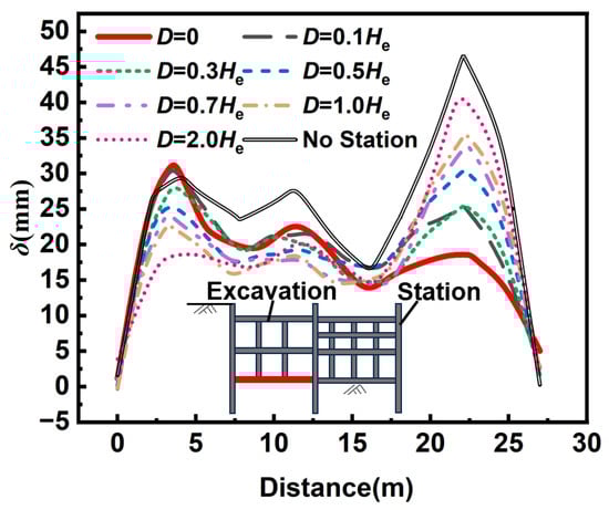
Figure 7.
Vertical deformation of the excavation’s base slab under different distances.
The coupling mechanism underlying this deformation trend can be attributed to two aspects: First, in conditions without station influence or at larger spacings, the asymmetric arrangement of internal columns induces uneven loading, resulting in non-uniform base-slab deformation. Second, the existing station, with its considerable stiffness and width, imposes a substantial constraint on the adjacent side of the base slab, reducing the heave in the shared-wall condition to approximately 39.74% of that observed in the scenario without the station.
To investigate the existing metro station’s influence, we plot the relationship between the maximum diaphragm wall deflection on the station side (δhm) and the excavation depth (He) (Figure 8). Herein, the green line represents the maximum and minimum values of the ratio between the diaphragm wall deformation and the corresponding excavation depth at each construction stage under the condition without a station; the pink dashed line represents the maximum and minimum values of the ratio between the diaphragm wall deformation and the corresponding excavation depth at each construction stage under different D conditions for the foundation pit and the station. It is observed that without a nearby station, δhm typically ranges from 0.10% He to 0.13% He. Conversely, when the excavation is adjacent to an existing station, the maximum wall deflection is significantly reduced, with δhm generally falling between 0.02% He and 0.12% He. This restraining effect becomes more pronounced as excavation depth increases. For instance, under the shared-wall condition with He = 3.2 m, 13.2 m, 21.5 m, and 23.2 m, the station-side δhm is only 60.59%, 31.65%, 21.55%, and 20.26%, respectively, of the value without the station. As the horizontal distance D increases, convergence toward the free-field condition slows down. Taking He = 23.2 m as an example, at D = 0, 0.3 He, 0.5 He, 0.7 He, and 2.0 He, the station-side δhm recovers to 20.26%, 49.51%, 67.99%, 80.11%, and 96.10%, of the non-station case, respectively. These results indicate that the existing station’s influence on wall deformation gradually diminishes as D increases.
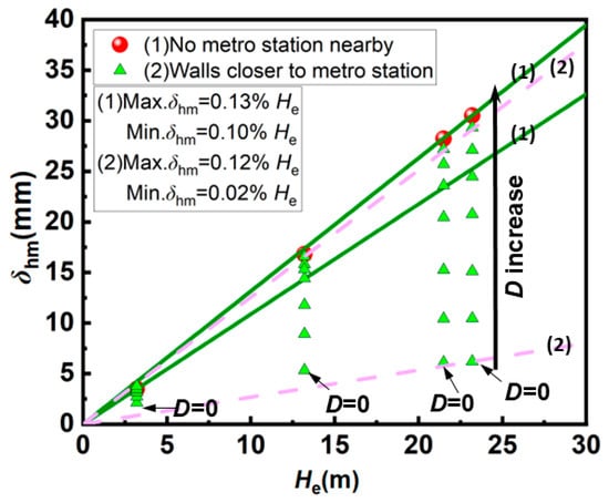
Figure 8.
Relationship between maximum lateral deformation of existing station diaphragm wall and excavation depth.
3.2. Excavation-Induced Deformation Pattern of the Shared-Wall Existing Station
To evaluate the excavation’s impact on the existing station, the differential settlement Δ between the base slab ends and the inclination ratio ωr (ωr = Δ/L, where L is the slab length) serve as the primary indices. Positive ωr values denote a clockwise rotation, as illustrated in Figure 9. Under non-shared-wall conditions (0.1 He ≤ D ≤ 0.7 He), the existing station’s base slab exhibits a counterclockwise rotation. Specifically, at D = 0.1 He, ωr reached −25.67 × 10⁻⁶ after the first excavation stage. This trend intensified during roof-slab installation, peaking at −31.96 × 10⁻⁶. Although minor clockwise fluctuations occurred in subsequent steps (Δωr ranges from +0.67 × 10⁻⁶ to +14.77 × 10⁻⁶), the overall behavior remained dominated by a counterclockwise rotation, ending at −13.23 × 10⁻⁶. As the distance increased to 1.0 He ≤ D ≤ 2.0 He, the slab no longer showed persistent unidirectional inclination. At D = 1.0 He, the final ωr was merely −0.391 × 10⁻⁶, displaying slight fluctuations: an initial clockwise phase (max +0.03 × 10⁻⁶ to +3.68 × 10⁻⁶), followed by a counterclockwise shift. This suggests negligible excavation impact at such distances. Conversely, the shared-wall condition consistently induced pronounced clockwise inclination. The base slab immediately rotated clockwise after the first stage (ωr = +10.71 × 10⁻⁶), accumulating further rotation with each step until it stabilized at +66.45 × 10⁻⁶.
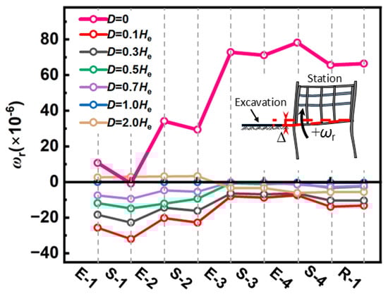
Figure 9.
Variation in the tilt ratio of the existing station’s base slab with excavation under different distances.
The opposing inclination trends between shared-wall and non-shared-wall conditions stem from a transition in the dominant deformation mechanism: from external ground settlement to excavation-bottom unloading heave. In non-shared-wall cases, the station lies within the settlement trough behind the retaining structure. The soil near the excavation settles more significantly due to wall deflection and ground loss, causing greater downward displacement at the slab’s near-excavation end, hence the counterclockwise rotation. In contrast, under the shared-wall condition, the station’s existing diaphragm wall directly serves as the retaining structure. Excavation induces significant rebound at the excavation bottom, exerting heave on the station’s near- excavation side, while the far-excavation side remains governed by its own weight. This asymmetric loading eventually causes the station to rotate clockwise, moving it away from the excavation. The observed reversal of the base slab rotation mode under shared-wall conditions provides a crucial supplement to existing theories. Previous studies by Li et al. [24,25] primarily focused on the deformation of stations within the settlement trough, emphasizing a ‘counter-clockwise tilt toward the excavation’ driven by ground loss. While our results for non-shared-wall cases (D ≥ 0.1 He) align with these findings, the shared-wall configuration (D = 0) triggers a dominant ‘clockwise rotation away from the excavation’. This phenomenon confirms that when the soil buffer is absent, the mechanical interaction shifts from being settlement-driven to rebound-driven.
Figure 10 presents the ground-surface settlement profiles on the existing station’s side at various spacing distances, D. For the shared-wall case (D = 0 m), the ground surface adjacent to the station exhibits significant heave rather than settlement, peaking at 0.007% He. This deformation is typical of the shared-wall configuration. Since the diaphragm wall of the existing station is integrated into the retaining system, the excavation-induced rebound of the excavation base is directly transmitted to the station’s structure. Consequently, the station heaves as a whole, driving the overlying soil upward; thus, the maximum heave occurs directly above the shared diaphragm wall. As D increases, the settlement profile evolves into a distinct “double-trough” pattern, comprising “Settlement Trough I” near the excavation and “Settlement Trough II” behind the station. Trough I consistently maintains a steep concave shape, and its peak settlement increases significantly with D. Specifically, when D increases from 0.1 H to 1.0 He, the peak value of Trough I rises from 0.003% He to 0.077% He, indicating an increment of 0.075% He. Conversely, the peak settlement of Trough II remains minor, reaching only 0.007% He at D = 2.0 He. Across all non-zero spacing scenarios, the settlement magnitude of Trough I consistently exceeds that of Trough II. However, both are notably smaller than the maximum of 0.078% He observed in the no-station scenario, demonstrating that the existing station significantly constrains soil unloading and mitigates excavation-induced ground-surface settlement.
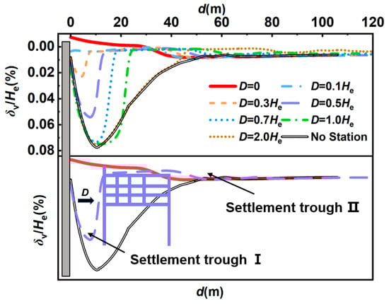
Figure 10.
Ground settlement on existing station side during excavation under different distances.
Figure 11 illustrates the relationship between the maximum ground-surface settlement on the station side, δvm, and the final excavation depth, He. Herein, the green line represents the maximum and minimum values of the ratio between surface settlement and the corresponding excavation depth at each construction stage under the condition without a station; the pink dashed line represents the maximum and minimum values of the ratio between surface settlement and the corresponding excavation depth at each construction stage under different D conditions for the foundation pit and the station. In the absence of an adjacent subway station, δvm generally ranges from approximately 0.078% He to 0.082% He. Conversely, when the excavation is adjacent to an existing station, δvm varies between 0.006% He and 0.083% He, where the settlement on the station side gradually approaches the magnitude observed in the no-station condition as the spacing D increases. For example, at He = 23.2 m, when D is set to 0, 0.3 He, 0.5 He, 0.7 He, and 2.0 He, the resulting δvm values account for 10.37%, 27.39%, 64.84%, 87.11%, and 93.36% of the maximum settlement in the no-station case, respectively. These results demonstrate that the influence of the existing station on excavation-induced surface settlement diminishes as the spacing, D, increases.
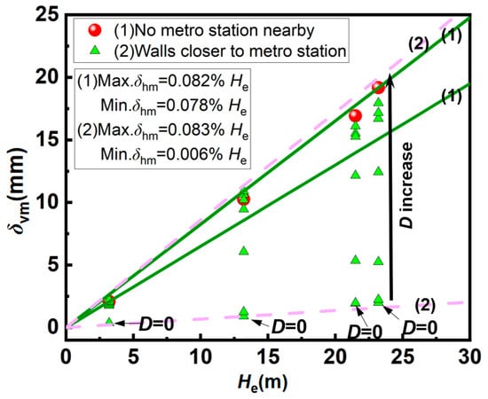
Figure 11.
Relationship between maximum ground settlement on existing station side and final excavation depth.
3.3. Deformation Mechanism of Adjacent Bridge Piles Considering Influence of Existing Structures
To investigate the influence of the existing station on adjacent bridge piles, the piles closest to the excavation were selected for analysis under both the no-station and shared-wall conditions. Their horizontal displacement responses during excavation were evaluated, with movement toward the excavation defined as negative values (Figure 12). In the no-station scenario (Figure 12a), the pile head exhibits significantly larger horizontal displacement than the pile toe, and this discrepancy widens as excavation proceeds. Specifically, from excavation Stage 1 to Stage 4, the displacement at the pile head increases from 0.68 mm to 3.95 mm, while that at the pile toe rises from 0.22 mm to 2.68 mm. For the shared-wall condition, the displacement pattern during the initial two stages mirrors that of the no-station case, although the magnitudes are slightly larger; however, the displacement distribution subsequently reverses. From Stage 2 to Stage 4, displacement at the pile head decreases from 2.18 mm to 1.28 mm, whereas that at the pile toe increases from 1.53 mm to 3.50 mm (Figure 12b). This behavior is attributed to the high stiffness and large width of the existing station, which impose substantial constraints on the near-surface soil. While excavation induces overall horizontal soil movement on the station side, the soil surrounding the upper pile shaft is restrained by the station’s structure. In contrast, the lower portion of the pile experiences weaker confinement due to the limited influence of the station at that depth. Consequently, the pile undergoes a clockwise rotation, resulting in distinct displacement responses between the upper and lower segments.
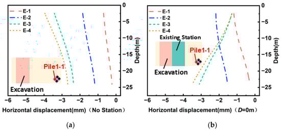
Figure 12.
Horizontal displacement of bridge piles with/without the existing station during excavation: (a) without the existing station and (b) with the existing station.
Furthermore, the “shielding effect” exerted by the station on adjacent bridge piles reveals a more complex three-party interaction than previously reported. Existing research on pile-excavation interaction (e.g., Wu et al. [36]) typically describes a cantilever-like deformation pattern for piles adjacent to excavations. However, in this study, comparative analysis shows that the presence of a shared-wall station fundamentally changes the pile’s deformation profile, shifting the maximum displacement from the pile head to the pile toe. This indicates that the high stiffness of the station acts as a rigid barrier, shielding the upper portion of the piles from near-surface soil movement.
Figure 13a compares the final horizontal displacements of multiple bridge piles under both the no-station condition and the shared-wall excavation–station condition. In the shared-wall scenario, the horizontal displacement of the piles decreases progressively with increasing horizontal distance from the excavation. The maximum displacement occurs at the pile toe, where the magnitude reduces from 3.46 mm to 1.63 mm as the horizontal distance increases. Although the no-station condition exhibits a similar decreasing trend with distance, notable differences exist in both the location and magnitude of the maximum displacement. Without the station, the maximum horizontal displacement shifts upward to the pile head, and its value decreases from 3.92 mm to 2.22 mm, indicating that the overall displacement levels are higher than those observed in the shared-wall condition.
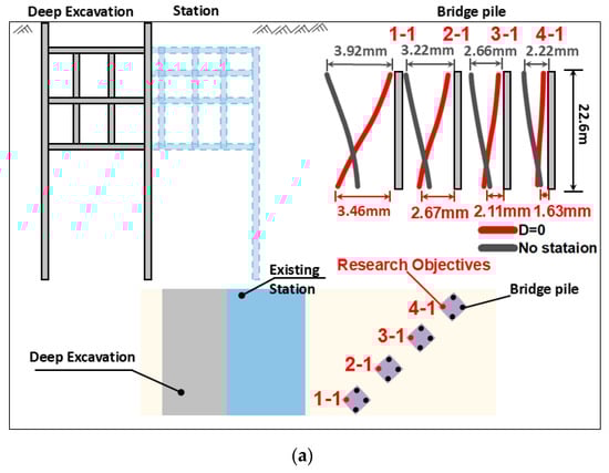
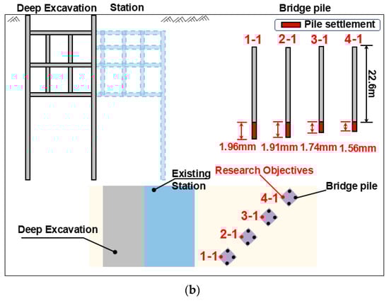
Figure 13.
Final displacement of bridge pile foundations: (a) final horizontal displacement of multiple bridge piles with/without the existing station and (b) settlement of bridge pile foundations under shared wall conditions.
The influence of excavation on the horizontal deformation of bridge piles weakens with increasing horizontal distance from the excavation in both scenarios. However, due to the rigid constraint of the existing station in the shared-wall condition, the overall pile displacement is reduced, and the critical location of the maximum displacement transfers from the pile head in the no-station case to the pile toe when the station shares the retaining wall. This contrast provides important guidance for controlling the deformation of bridge piles adjacent to deep excavations.
Figure 13b illustrates the final settlement distribution characteristics of multiple bridge pile foundations under the shared-wall condition. The pile settlement gradually decreases with increasing horizontal distance from the deep excavation. Among them, the pile labeled 1-1, closest to the excavation, exhibits the maximum settlement of 1.96 mm, whereas the farthest one, labeled 4-1, shows a settlement of 1.56 mm. The difference in settlement between these two piles is 0.40 mm. Thus, under this condition, the excavation exerts a relatively limited influence on the settlement of the surrounding bridge pile foundations.
Figure 14 presents the bending moment variation in the pile foundations during excavation under the shared-wall condition. Bending moments are negative when the pile is under tension toward the excavation. During the first two excavation steps, the pile’s bending moment magnitude only changes slightly. In this stage, the pile exhibits a pattern where the upper portion is in tension on the excavation side, while the lower portion is in tension on the side away from the excavation, corresponding to an inclination of the upper section toward the excavation and the lower section away from it. After the subsequent two steps are completed, the tensile side of the upper portion reverses from the excavation side to the side away from the excavation, with the maximum positive bending moment reaching 235.63 kN·m. The lower portion remains under tension on the side away from the excavation, but its bending moment magnitude decreases markedly with excavation, from an initial 1260 kN·m to 769.69 kN·m. The combination of upper bending moment reversal and the substantial reduction in the lower bending moment leads to increased displacement at the pile base and reduced displacement at the pile head, ultimately causing a reversal of the pile deformation trend. This behavior is fully consistent with the deformation features presented in Figure 12.
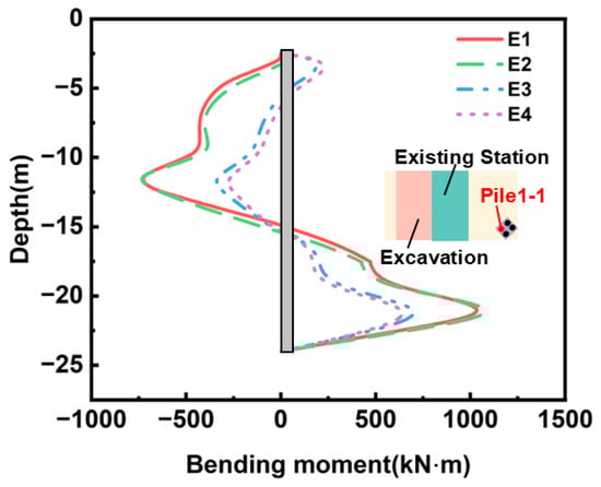
Figure 14.
Bending moment of the bridge pile foundation.
To systematically elucidate the “excavation-station-pile” coupling mechanism, the specific force transfer paths are identified as follows. In the shared-wall system, the force transfer from the excavation to the station is direct rather than soil-mediated, with the basal rebound force transmitted through the shared diaphragm wall to drive the station’s clockwise tilt. Acting as a stiffness barrier, the station intercepts lateral soil movement and significantly redistributes the soil pressure field. Accordingly, the force transfered to the bridge piles is filtered by the station’s structure, which shields the upper pile segments from horizontal soil thrust and redirects displacement demands to deeper soil layers, thereby defining the piles as passive responders within this three-party coupled environment.
4. Parametric Study
4.1. Thickness of the Shared Diaphragm Wall
Figure 15 systematically analyzes the influence of shared diaphragm wall thickness on the deformation response of the existing metro station under shared-wall conditions. As illustrated in Figure 15a, increasing the wall thickness (d) from 0.6 m to 1.2 m causes the maximum horizontal displacement to decrease from 12.65 mm to 6.37 mm, exhibiting a declining trend. However, the depth of this maximum displacement remains constant at approximately 19.50 m, showing no vertical shift with thickness variations. Figure 15b indicates that as thickness decreases, ground heave in the 0–25 m heave zone adjacent to the station intensifies, with peak surface heave rising from 0.73‱ He to 0.88‱ He. Similarly, in the settlement trough located roughly 40 m from the excavation, maximum ground settlement expands, with the peak value growing from 0.82‱ He to 0.85‱ He. These behaviors are attributed to two mechanisms: First, increasing the shared wall’s thickness enhances bending stiffness, limiting lateral flexure under identical excavation loads. Since the existing station provides a stable constraint, the wall’s deformation mode remains consistent across varying thicknesses, ensuring that the maximum displacement depth remains invariant. Second, a thicker wall improves the station–wall system’s overall stability, mitigating the extent and degree of surrounding ground disturbances.
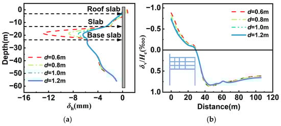
Figure 15.
Deformation of the existing station under different shared wall thicknesses: (a) horizontal deformation of the shared wall and (b) ground settlement on the existing station’s side.
4.2. Depth of Shared Diaphragm Wall
Figure 16 reveals the influence of the shared diaphragm wall’s length on the deformation response of the existing metro station, where the excavation and the station share a common wall. As depicted in Figure 16a, increasing the wall length from H = 56 m to H = 72 m causes the maximum horizontal displacement to rise from 6.25 mm to 7.18 mm. However, the depth of this maximum displacement remains stable at approximately 19.50 m, showing no vertical shift. This behavior is attributed to the increased slenderness ratio (length to radius of the gyration ratio) and results in greater lateral deflection under identical lateral earth pressure.
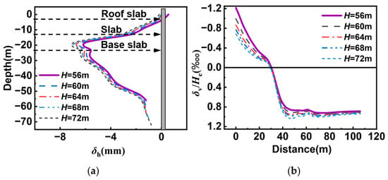
Figure 16.
Deformation of the existing station with shared walls of different depths: (a) horizontal deformation of the shared wall and (b) ground settlement on the existing station’s side.
Figure 16b indicates that as the shared wall’s length increases, ground heave adjacent to the excavation decreases, while the settlement trough farther away intensifies. Within the 0–25 m heave zone behind the wall, the maximum ground heave drops from 1.21‱ He to 0.68‱ He. Simultaneously, at approximately 40 m from the excavation, the peak settlement at the trough increases from 0.86‱ He to 1.03‱ He. This physical mechanism is driven by the increase in total structural weight due to the longer wall, imposing a greater vertical surcharge on the surrounding soil. This additional load counteracts ground heave in the near field while aggravating settlement in the far field.
5. Conclusions
Based on the Tianjin Binhai International Airport Comprehensive Transportation Hub Project, this study establishes a refined three-dimensional numerical model of the coupled “deep excavation-existing metro station-bridge pile” system to investigate the asymmetric deformation mechanism of deep excavations adjacent to metro stations and elevated-bridge piles in soft soil regions. On this basis, the effects of different spacings and the shared-wall constraint on the deformation patterns of both the excavation and the existing station are examined. The coupling mechanism through which the existing station influences the deformation of adjacent bridge piles is clarified, and the deformation responses associated with changes in the thickness and depth of the shared diaphragm wall are analyzed. The key conclusions are as follows:
- Asymmetric constraint mechanism: The existing station acts as a high-stiffness boundary that fundamentally modifies the excavation’s deformation pattern. Under the shared-wall condition (D = 0), lateral displacement and basal heave on the near side are effectively suppressed. This restraint decays nonlinearly and becomes negligible once the spacing exceeds 2.0 He.
- Deformation mode reversal: Under non-shared scenarios, the station tilts “counter-clockwise toward the excavation” due to ground loss; however, in shared-wall systems, the station exhibits “clockwise tilting away from the excavation,” which is directly driven by excavation-induced basal rebound transferred through the shared diaphragm wall.
- Shielding effect on piles: The station exerts a significant “shielding effect” on adjacent bridge piles. It restricts shallow soil movement, shifting the pile deformation pattern from a cantilever mode to a deep lateral displacement profile, where the maximum displacement occurs at the pile toe instead of the head.
- Practical implementation and design: Effectively controlling station deformation requires optimizing both shared wall thickness and depth. Designers should shift the priority from traditional settlement control to anti-heave measures. Furthermore, monitoring strategies for adjacent piles must extend to the pile toes to capture the depth-dependent shielding response.
While this study provides insights into the asymmetric coupling mechanism, certain limitations are acknowledged. First, a quasi-3D numerical model was adopted by selecting a representative segment along the longitudinal direction of the excavation; therefore, the full 3D corner effects and longitudinal variations may not be completely captured when compared to a full-scale 3D model. Second, certain simplifications were made during structural modeling and when determining soil–structure interface properties, which might influence the precision of local stress distributions. Finally, the current research lacks a comprehensive uncertainty analysis of the stochastic nature of soil properties and construction-induced disturbances, and a generalized empirical formula for rapid engineering assessments has yet to be established. These aspects remain as subjects for future research to further refine the predictive capabilities of the model in similar complex environments.
Author Contributions
Conceptualization, Y.M.; methodology, Y.M. and M.K.; writing—original draft M.K.; validation, H.L.; formal analysis, H.L.; software, J.Z.; resources, J.Z., X.Y. and J.H.;Investigation, X.Y.; funding acquisition J.H.; data curation, S.H.; writing—review and editing, J.S.; visualization, X.C.; supervision, G.Z.; Project administration X.C. and G.Z. All authors have read and agreed to the published version of the manuscript.
Funding
This research was funded by the Project of National Key R&D Program of China (Grant No. 2023YFC3009300) and the Tianjin Transportation Science and Technology Project (Grant No. 2025-66). Their support is gratefully acknowledged.
Data Availability Statement
The data that support the findings of this study are available from the corresponding author upon reasonable request.
Conflicts of Interest
Authors Yunkang Ma, Xiangjian Yin and Jinjin Hao were employed by the company Tianjin Metro Group Co., Ltd. The remaining authors declare that the research was conducted in the absence of any commercial or financial relationships that could be construed as a potential conflict of interest.
References
- Tan, Y.; Wang, D. Characteristics of a large-scale deep foundation pit excavated by the central-island technique in Shanghai soft clay. II: Top-down construction of the peripheral rectangular pit. J. Geotech. Geoenviron. Eng. 2013, 139, 1894–1910. [Google Scholar] [CrossRef]
- Tan, Y.; Wei, B.; Zhou, X.; Diao, Y. Lessons learned from construction of Shanghai metro stations: Importance of quick excavation, prompt propping, timely casting, and segmented construction. J. Perform. Constr. Facil. 2015, 29, 04014096. [Google Scholar] [CrossRef]
- Tan, Y.; Wei, B.; Diao, Y.; Zhou, X. Spatial corner effects of long and narrow multipropped deep excavations in Shanghai soft clay. J. Perform. Constr. Facil. 2014, 28, 04014015. [Google Scholar] [CrossRef]
- Jia, Y.; Cao, Z.; Li, Z.; Du, F.; Huang, C.; Lin, H.; Wang, W.; Zhai, M. Nonlinear evolution characteristics and seepage mechanical model of fluids in broken rock mass based on the bifurcation theory. Sci. Rep. 2024, 14, 10982. [Google Scholar]
- Lin, H.; Zhang, W.; Guo, S.; Zhang, X.; Wang, L.; Zhang, J. Study on the energy evolution mechanism and fractal characteristics of coal failure under dynamic loading. ACS Omega 2025, 10, 54710–54719. [Google Scholar] [CrossRef] [PubMed]
- Tan, Y.; Wang, D. Characteristics of a large-scale deep foundation pit excavated by the central-island technique in Shanghai soft clay. I: Bottom-up construction of the central cylindrical shaft. J. Geotech. Geoenviron. Eng. 2013, 139, 1875–1893. [Google Scholar] [CrossRef]
- Zhen, J.; Zheng, G.; Huang, J.; Lin, S.; Pei, H.; Gao, S.; Li, Q.; Cheng, X. Deformation and Control of Metro Structures during Asymmetric Bilateral Zero-Distance Excavations. Int. J. Geomech. 2025, 25, 05025008. [Google Scholar] [CrossRef]
- Zheng, G.; Huang, J.; Diao, Y.; Yan, Y.; Jiao, C.; Zhang, L.; Jia, J.; Peng, J. Field Investigation of Deflection Characteristics and Control Strategies of a Short Floating Pile Adjacent to Deep Excavation. J. Geotech. Geoenviron. Eng. 2025, 151, 05025001. [Google Scholar] [CrossRef]
- Xia, B.; Zheng, G.; Zhou, H.; He, Y. Evaluation of building damage caused by excavation-induced ground movements in three-dimensional deformation field: A case study in Tianjin, China. Acta Geotech. 2025, 20, 3795–3809. [Google Scholar] [CrossRef]
- Zeng, S.; Sun, H.; Tao, Y.; Pan, S.; Cai, Y. Multi-stage and multi-objective optimization framework for servo-controlled wall deflection during deep excavation. Can. Geotech. J. 2026, 63, 1–24. [Google Scholar] [CrossRef]
- Tao, Y.; Pan, S.; Sun, H.; Shen, W. Active adjustment of axial forces in excavations with servo steel struts. Acta Geotech. 2025, 1–19. [Google Scholar] [CrossRef]
- Tao, Y.; Zeng, S.; Ying, T.; Sun, H.; Pan, S.; Cai, Y. A deep transfer learning model for the deformation of braced excavations with limited monitoring data. J. Rock Mech. Geotech. Eng. 2025, 17, 1555–1568. [Google Scholar] [CrossRef]
- Shi, J.; Liu, G.; Huang, P.; Ng, C.W.W. Interaction between a large-scale triangular excavation and adjacent structures in Shanghai soft clay. Tunn. Undergr. Space Technol. 2015, 50, 282–295. [Google Scholar] [CrossRef]
- Liu, G.B.; Huang, P.; Shi, J.W.; Ng, C.W.W. Performance of a deep excavation and its effect on adjacent tunnels in Shanghai soft clay. J. Perform. Constr. Facil. 2016, 30, 04016041. [Google Scholar] [CrossRef]
- Liang, R.; Wu, J.; Sun, L.; Shen, W.; Wu, W. Performances of adjacent metro structures due to zoned excavation of a large-scale basement in soft ground. Tunn. Undergr. Space Technol. 2021, 117, 104123. [Google Scholar] [CrossRef]
- Liao, S.-M.; Wei, S.-F.; Shen, S.-L. Structural responses of existing metro stations to adjacent deep excavations in Suzhou, China. J. Perform. Constr. Facil. 2016, 30, 04015089. [Google Scholar] [CrossRef]
- Deng, X.; Zheng, H.; Song, Z.; Wang, J. Deformation analysis of deep foundation pit works adjacent to a new subway station. J. Undergr. Space Eng. 2018, 14, 270–277. (In Chinese) [Google Scholar]
- Chen, S.-L.; Zhang, F.; Dai, N. Studies on stress and deformation behaviors of deep excavations adjacent to substructures. J. Shanghai Jiaotong Univ. 2016, 50, 1658–1664. (In Chinese) [Google Scholar]
- Zhou, F.; Zhou, P.; Li, J.; Lin, J.; Ge, T.; Deng, S.; Ren, R.; Wang, Z. Deformation characteristics and failure evolution process of the existing metro station under unilateral deep excavation. Eng. Fail. Anal. 2022, 131, 105870. [Google Scholar] [CrossRef]
- Wang, Z.; Zhou, F.; Zhou, P.; Jiang, Y.; Deng, S.; Ren, R. Research on deformation theory of existing stations based on single side excavation and unloading of large foundation pits with strong close connection. Chin. J. Rock Mech. Eng. 2020, 39, 2131–2147. (In Chinese) [Google Scholar]
- Yin, H.; Wang, S.; Wang, D.; Dong, Z.; Gao, Z.; Zhang, Z. Sheltering effect induced by established station to the new station excavation in Zhengzhou. Arch. Civ. Mech. Eng. 2023, 23, 175. [Google Scholar] [CrossRef]
- Hou, Y.M.; Wang, J.H.; Zhang, L.L. Finite-element modeling of a complex deep excavation in Shanghai. Acta Geotech. 2009, 4, 7–16. [Google Scholar] [CrossRef]
- Yang, T.; Xiong, S.; Liu, S.; Liu, Y.; Zhao, H.; Li, Y. Numerical analysis of the influence of deep foundation pit construction on adjacent subway stations in soft soil areas. Adv. Civ. Eng. 2022, 2022, 6071868. [Google Scholar] [CrossRef]
- Li, M.-G.; Wang, J.-H.; Chen, J.-J.; Zhang, Z.-J. Responses of a newly built metro line connected to deep excavations in soft clay. J. Perform. Constr. Facil. 2017, 31, 04017096. [Google Scholar] [CrossRef]
- Li, M.-G.; Xiao, X.; Wang, J.-H.; Chen, J.-J. Numerical study on responses of an existing metro line to staged deep excavations. Tunn. Undergr. Space Technol. 2019, 85, 268–281. [Google Scholar] [CrossRef]
- Yu, C.; Long, J.; Lu, M. Study on the influence of deep foundation pit excavation on adjacent metro structure. IOP Conf. Ser. Earth Environ. Sci. 2021, 768, 012101. [Google Scholar] [CrossRef]
- Xiang, X. Comparative analysis of deformation of adjacent station caused by different construction sequence of foundation pit. J. Railw. Eng. 2015, 32, 80–85. (In Chinese) [Google Scholar]
- Ou, X.; Zhang, X.; Fu, J.; Zhang, C.; Zhou, X.; Feng, H. Cause investigation of large deformation of a deep excavation support system subjected to unsymmetrical surface loading. Eng. Fail. Anal. 2020, 107, 104202. [Google Scholar] [CrossRef]
- Liu, B.; Zhang, D.; Xi, P. Influence of vehicle load mode on the response of an asymmetrically-loaded deep excavation. KSCE J. Civ. Eng. 2019, 23, 3315–3329. [Google Scholar] [CrossRef]
- Xu, C.; Xu, Y.; Sun, H.; Chen, Q. Characteristics of braced excavation under asymmetrical loads. Math. Probl. Eng. 2013, 2013, 452534. [Google Scholar] [CrossRef]
- Guo, P.; Gong, X.; Wang, Y. Displacement and force analyses of braced structure of deep excavation considering unsymmetrical surcharge effect. Comput. Geotech. 2019, 113, 103102. [Google Scholar] [CrossRef]
- Liu, S.; Yang, J.; Fu, J.; Zheng, X. Performance of a deep excavation irregular supporting structure subjected to asymmetric loading. Int. J. Geomech. 2019, 19, 05019007. [Google Scholar] [CrossRef]
- Wang, H. Effect of genetic algorithm in optimizing deep foundation pit supporting structure. Arab. J. Geosci. 2021, 14, 266. [Google Scholar] [CrossRef]
- Zhang, W.; Wu, N.; Jia, P.; Zhou, X.; Li, H.; Wang, G. Study of the mechanical performance of excavation under asymmetrical pressure and reinforcement measures. Arab. J. Geosci. 2021, 14, 1834. [Google Scholar] [CrossRef]
- Lei, H.; Zhan, B.; Feng, S.; Amin, M. Influence of foundation pit groups’ excavation on the deformation characteristics of adjacent railway subgrade and protection measures. Geotech. Geol. Eng. 2023, 41, 3877–3895. [Google Scholar] [CrossRef]
- Wu, J.; Yu, J.; Fang, F.; Lin, G.; Tang, X.; Ding, H.; Xu, C. Impact of Excavation on Adjacent Elevated Bridges and Optimization Analysis of Deformation Control. Buildings 2024, 14, 3197. [Google Scholar] [CrossRef]
Disclaimer/Publisher’s Note: The statements, opinions and data contained in all publications are solely those of the individual author(s) and contributor(s) and not of MDPI and/or the editor(s). MDPI and/or the editor(s) disclaim responsibility for any injury to people or property resulting from any ideas, methods, instructions or products referred to in the content. |
© 2026 by the authors. Licensee MDPI, Basel, Switzerland. This article is an open access article distributed under the terms and conditions of the Creative Commons Attribution (CC BY) license.