Evaluation Framework for Inter-Module Connections in Steel–Concrete Composite Modular Structures



Abstract
1. Introduction
1.1. Modular Construction Background
1.2. Steel–Concrete Composite Modules
1.3. Inter-Module Connection Importance
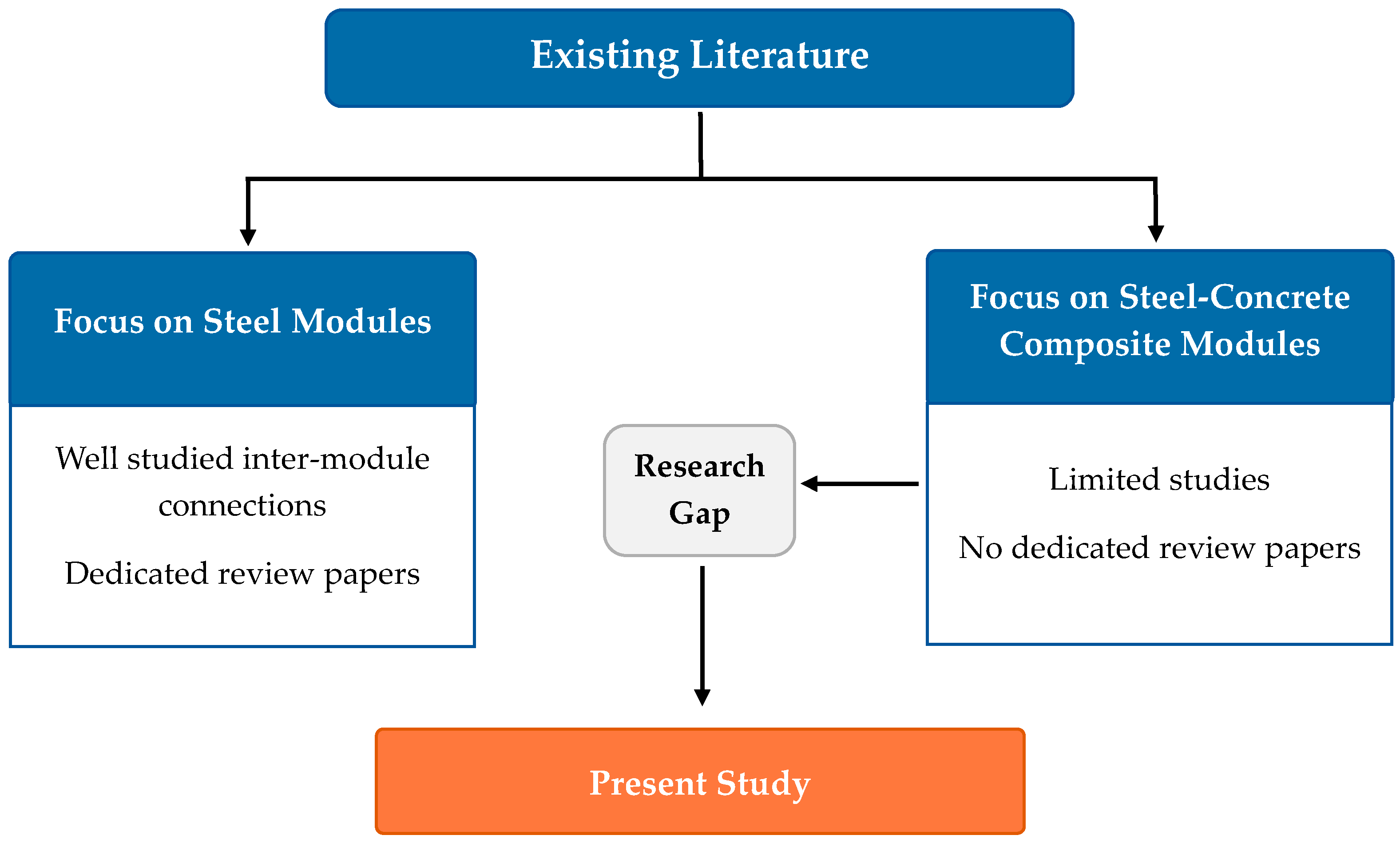
1.4. Aim and Scope of the Review
2. State-of-the-Art Reviews on Inter-Module Connection Technologies
3. Overview and Classification of Modular Connections
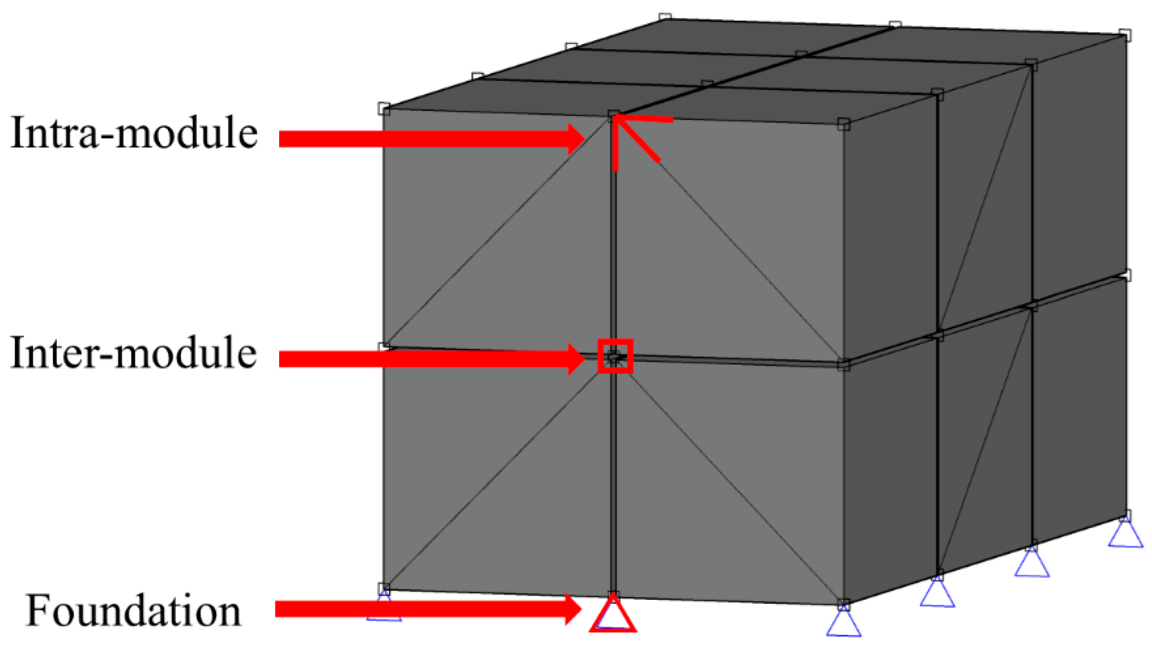
3.1. Classification and Types of Modular Connections
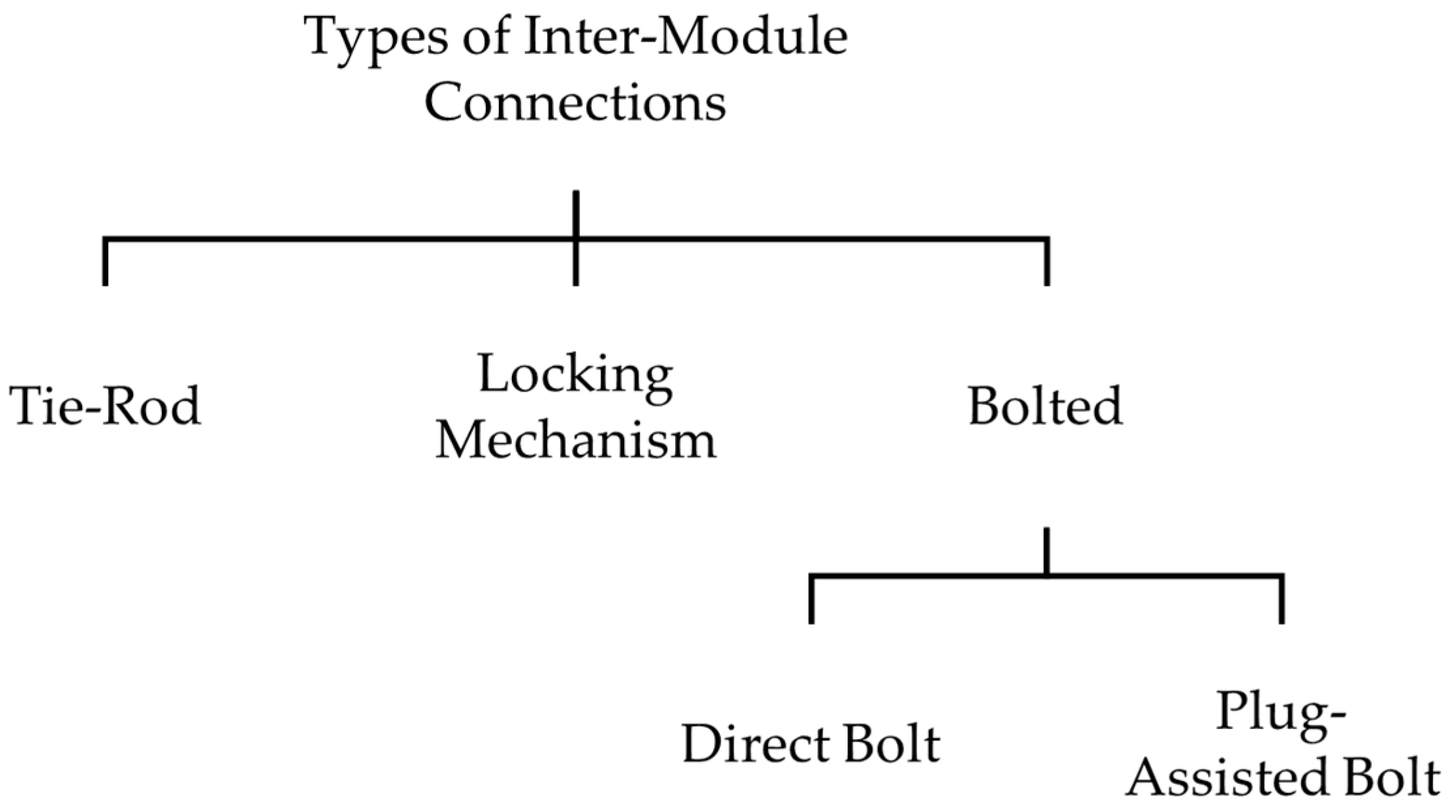
3.2. Classification and Types of Inter-Module Connections
3.3. Sub-Classification of Bolted Inter-Module Connections
3.4. Excluded Connection Types and Alternative Designs
4. Evaluation and Classification of Existing Inter-Module Connections
4.1. Review of Tie-Rod Inter-Module Connections
4.2. Review of Locking Mechanism Inter-Module Connections
4.3. Review of Direct Bolted Inter-Module Connections
4.4. Review of Plug-Assisted Bolted Inter-Module Connection
5. Evaluation Framework
5.1. Composite Compatibility Score (CCS)
5.2. Validation Evidence Score (VES)
5.3. Demountability and Reusability Score (DRS)
5.4. Normalised Capacity Index (NCI)
5.4.1. Capacity Adjustment Factor
- Ci is the original reported capacity.
- F is the Capacity Adjustment Factor.
5.4.2. Normalised Capacity Index (NCI) Computation
- NCIi,k is the Normalised Capacity Index for inter-module connection i under capacity type k.
- Ci,adj,k is the adjusted capacity of connection i for capacity type k.
- Cadj,k is the set of all adjusted capacities reported across all inter-module connections for capacity type k.
- max(Cadj,k) is the maximum adjusted capacity among all inter-module connections for capacity type k.
- NCITension;
- NCICompression;
- NCIMoment;
- NCIShear;
- NCILateral;
- NCISlip;
- NCIRotational Stiffness.
6. Performance Evaluation for Inter-Module Connections
6.1. Structural Performance Evaluation Using Normalised Capacity Index (NCI)
Scope of Normalised Capacity Index (NCI) Assessment
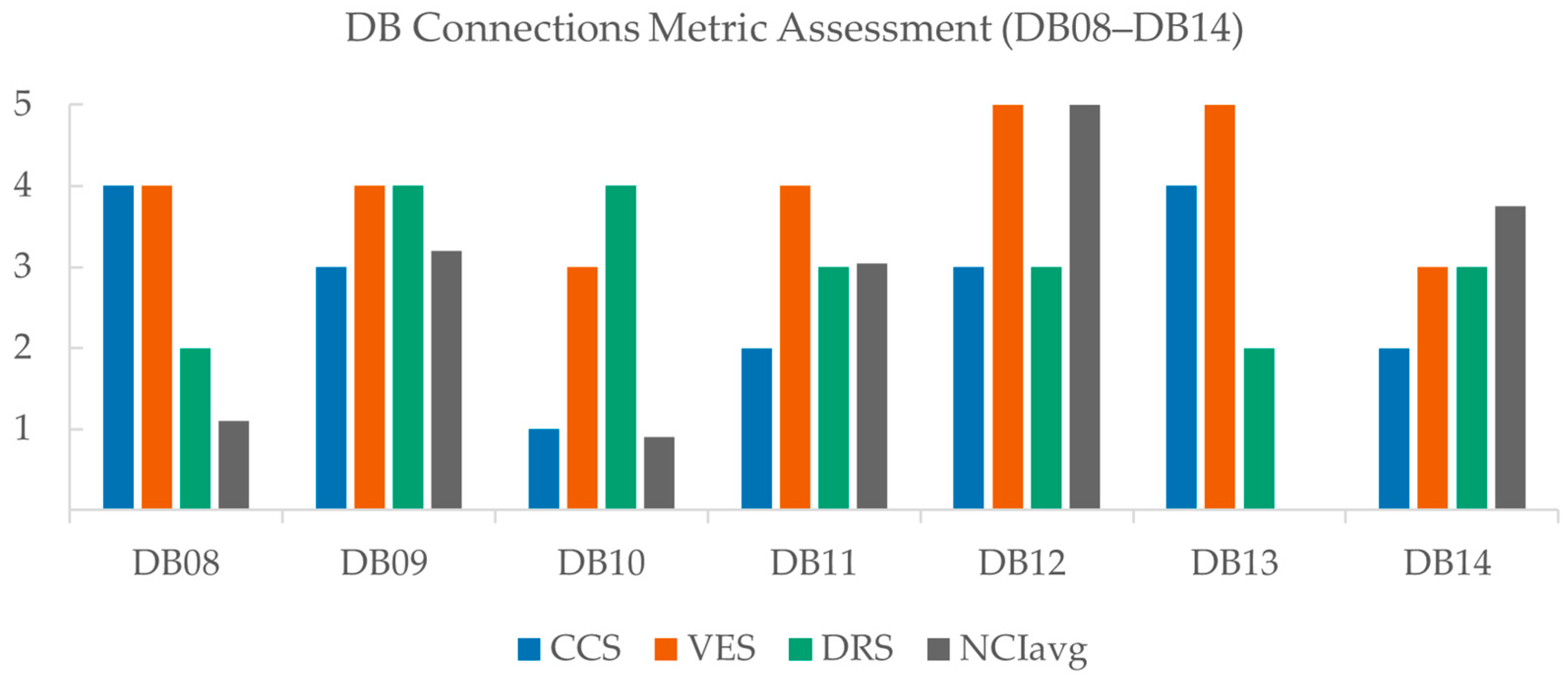
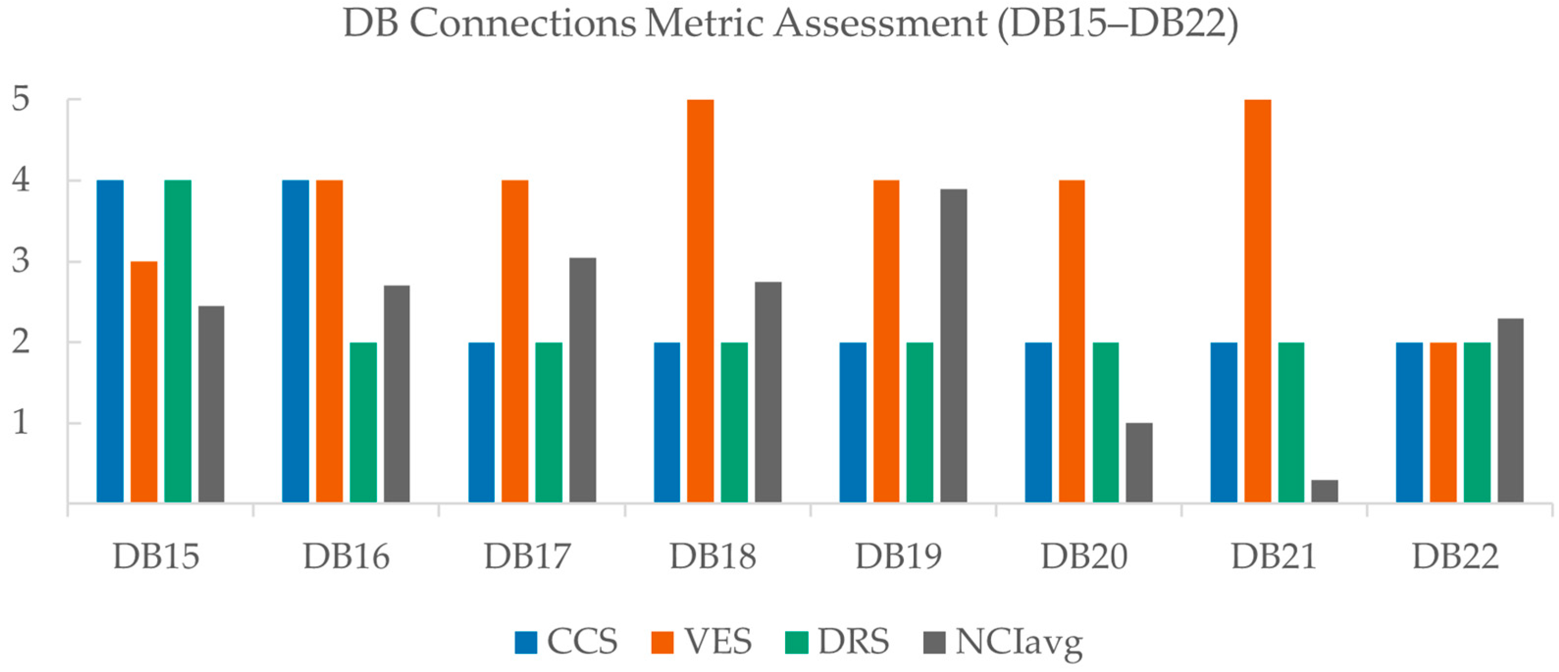
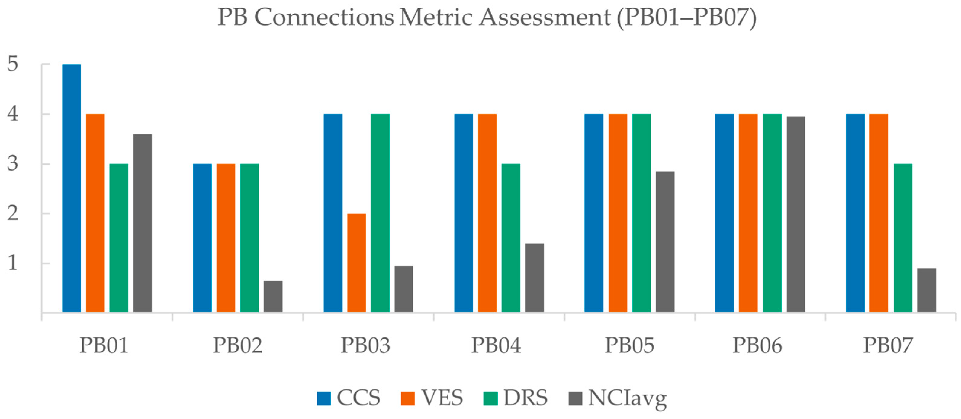
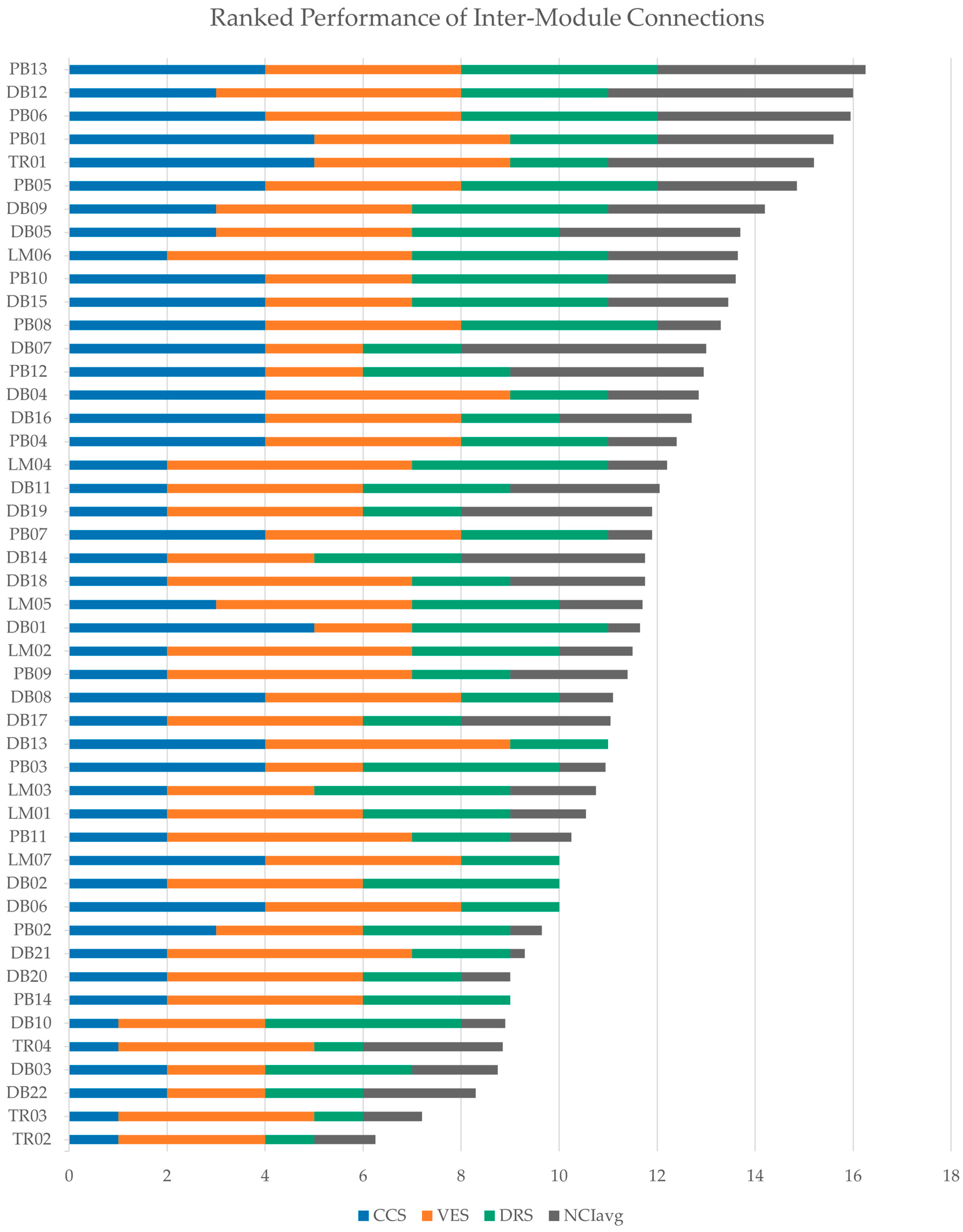
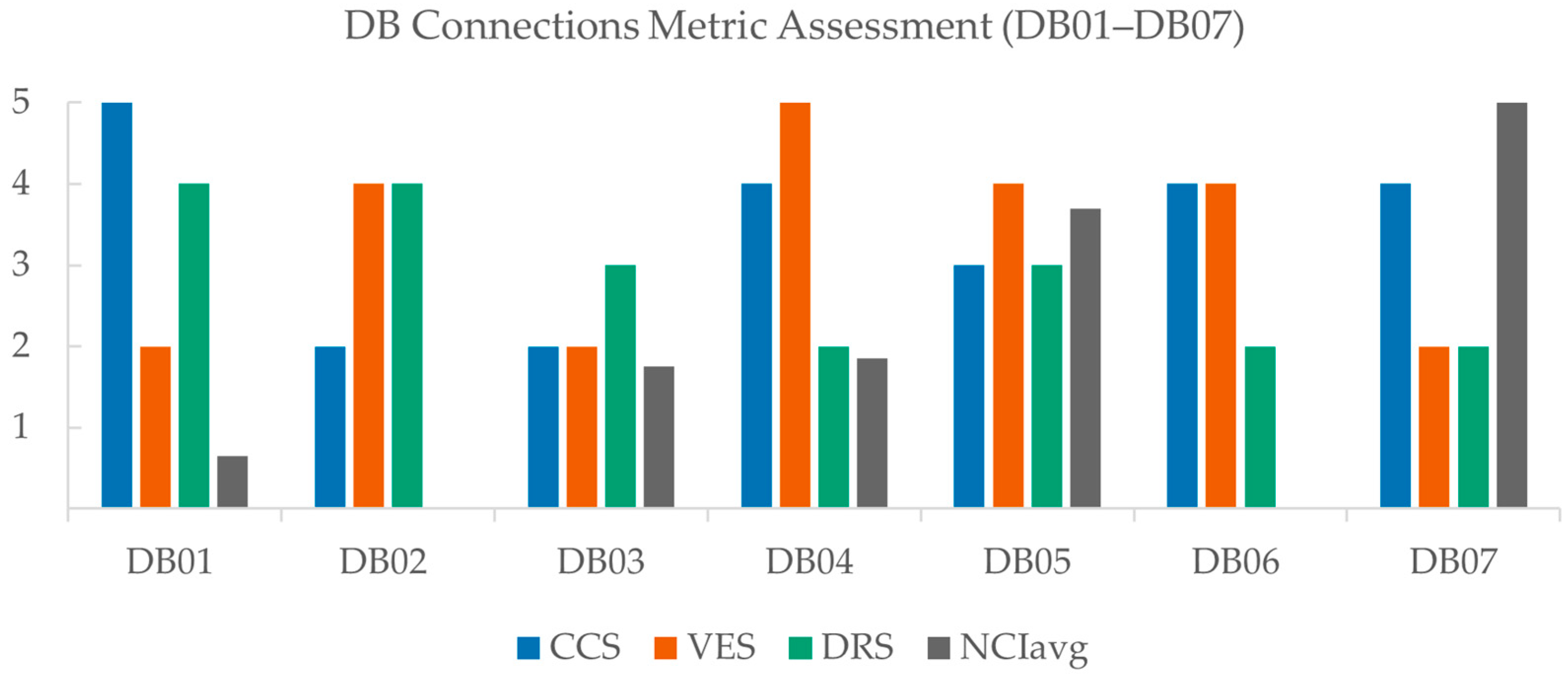
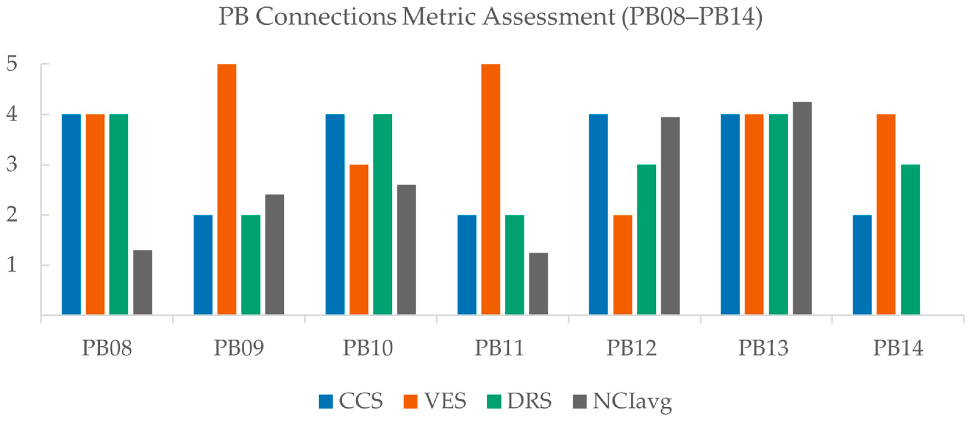
6.2. Comparative Performance Across Evaluation Metrics
7. Discussion of Inter-Module Connection Performance
7.1. Tie-Rod Inter-Module Connection Performance Discussion
7.2. Locking Mechanism Inter-Module Connection Performance Discussion
7.3. Direct Bolt Inter-Module Connection Performance Discussion
7.4. Plug-Assisted Bolt Inter-Module Connection Performance Discussion
7.5. Overall Inter-Module Connection Assessment
8. Conclusions and Recommendations
Author Contributions
Funding
Data Availability Statement
Acknowledgments
Conflicts of Interest
Appendix A. Reported Structural Capacity Values

| Connection ID | Axial Tension Capacity (kN) | Axial Compression Capacity (kN) | Moment Capacity (kN·m) | Shear Capacity (kN) | Maximum Lateral Load (kN) | Maximum Slip Resistance (kN) | Initial Rotational Stiffness (kN·m/rad) |
|---|---|---|---|---|---|---|---|
| TR01 | 242 | ||||||
| TR02 | 17 | ||||||
| TR03 | 96 | ||||||
| TR04 | 3575 | ||||||
| LM01 | 382 | 295 | |||||
| LM02 | 528 | 42 | 4658 | 155 | 2390 | ||
| LM03 | 690 | 369 | 14,100 | ||||
| LM04 | 293 | ||||||
| LM05 | 148 | 91 | |||||
| LM06 | 525 | 1046 | 458 | ||||
| LM07 | |||||||
| DB01 | 260 | ||||||
| DB02 | |||||||
| DB03 | 280 | ||||||
| DB04 | 343 | ||||||
| DB05 | 340 | ||||||
| DB06 | |||||||
| DB07 | 1600 | ||||||
| DB08 | 399 | ||||||
| DB09 | 255 | 13,645 | |||||
| DB10 | 289 | ||||||
| DB11 | 93 | 6065 | |||||
| DB12 | 250 | 8653 | |||||
| DB13 | 196 | ||||||
| DB14 | 209 | ||||||
| DB15 | 82 | ||||||
| DB16 | 1350 | ||||||
| DB17 | 560 | 1165 | |||||
| DB18 | 260 | 1168 | |||||
| DB19 | 526 | 1830 | |||||
| DB20 | 250 | ||||||
| DB21 | 288 | 100 | 2186 | ||||
| DB22 | 1350 | 95 | |||||
| PB01 | 165 | ||||||
| PB02 | 108 | ||||||
| PB03 | 72 | ||||||
| PB04 | 260 | ||||||
| PB05 | 117 | ||||||
| PB06 | 120 | ||||||
| PB07 | 419 | 199 | |||||
| PB08 | 105 | ||||||
| PB09 | 843 | 217 | 405 | ||||
| PB10 | 114 | ||||||
| PB11 | 99 | 52 | 59 | ||||
| PB12 | 1037 | ||||||
| PB13 | 347 | 12,659 | |||||
| PB14 |
Appendix B. Capacity Adjustment
Appendix B.1. Adjusted Capacity Factors
| Connection ID | ||||
|---|---|---|---|---|
| TR01 | 0.84 | 0.42 | 0.62 | 0.45 |
| TR02 | 1.64 | 1.81 | 1.92 | 2.25 |
| TR03 | 3.07 | 6.26 | 12.76 | |
| TR04 | 0.43 | 0.32 | 0.37 | |
| LM01 | 0.84 | 0.62 | 0.45 | |
| LM02 | 0.39 | 0.20 | 0.30 | 0.23 |
| LM03 | 0.68 | 0.50 | 0.37 | |
| LM04 | 1.13 | 1.13 | 1.10 | |
| LM05 | 1.42 | 1.41 | 1.10 | |
| LM06 | 1.55 | 2.40 | 3.70 | |
| LM07 | --- | --- | --- | --- |
| DB01 | 0.67 | 0.50 | 0.37 | |
| DB02 | 0.66 | 0.49 | 0.37 | |
| DB03 | 1.51 | 0.15 | 1.46 | 1.83 |
| DB04 | 0.68 | 0.50 | 0.37 | |
| DB05 | 1.60 | 1.00 | 0.61 | |
| DB06 | --- | --- | --- | --- |
| DB07 | 0.87 | 0.45 | 0.22 | |
| DB08 | 1.00 | 1.00 | 1.00 | |
| DB09 | 0.92 | 0.93 | 0.92 | |
| DB10 | 0.70 | 0.29 | 0.09 | |
| DB11 | 1.62 | 1.30 | 1.18 | 0.58 |
| DB12 | 1.75 | 1.85 | 1.91 | |
| DB13 | 0.99 | 0.74 | 0.37 | |
| DB14 | 1.66 | 1.65 | 1.10 | |
| DB15 | 1.45 | 0.72 | 1.19 | 0.94 |
| DB16 | 1.06 | 0.98 | 0.90 | |
| DB17 | 1.45 | 1.42 | 1.41 | |
| DB18 | 1.75 | 1.85 | 1.91 | |
| DB19 | 1.45 | 2.22 | 3.38 | |
| DB20 | 0.55 | 0.36 | 0.23 | |
| DB21 | 0.48 | 0.36 | 0.28 | |
| DB22 | 1.28 | 1.30 | 1.28 | |
| PB01 | 1.75 | 0.53 | 1.70 | 1.66 |
| PB02 | 1.71 | 2.28 | 3.85 | |
| PB03 | 0.81 | 0.33 | 0.60 | 0.45 |
| PB04 | 0.68 | 0.50 | 0.37 | |
| PB05 | 0.84 | 0.59 | 0.62 | 0.45 |
| PB06 | 1.13 | 0.79 | 1.13 | 1.10 |
| PB07 | 1.13 | 1.13 | 1.10 | |
| PB08 | 3.07 | 6.26 | 12.76 | |
| PB09 | 0.60 | 0.52 | 0.44 | |
| PB10 | 0.55 | 0.55 | 0.42 | 0.32 |
| PB11 | 1.10 | 0.99 | 1.09 | 1.10 |
| PB12 | 2.03 | 2.89 | 6.71 | |
| PB13 | 1.13 | 1.13 | 1.10 | |
| PB14 | 1.73 | 1.97 | 2.21 |
Appendix B.2. Adjusted Structural Capacity Values
| Connection ID | Axial Tension Capacity (kN) | Axial Compression Capacity (kN) | Moment Capacity (kN·m) | Shear Capacity (kN) | Maximum Lateral Load (kN) | Maximum Slip Resistance (kN) | Initial Rotational Stiffness (kN·m/rad) |
|---|---|---|---|---|---|---|---|
| TR01 | 101 | ||||||
| TR02 | 31 | ||||||
| TR03 | 96 | ||||||
| TR04 | 1519 | ||||||
| LM01 | 320 | 182 | |||||
| LM02 | 207 | 13 | 1830 | 553 | |||
| LM03 | 468 | 186 | 5193 | ||||
| LM04 | 332 | ||||||
| LM05 | 209 | 91 | |||||
| LM06 | 813 | 1621 | 710 | ||||
| LM07 | |||||||
| DB01 | 174 | ||||||
| DB02 | |||||||
| DB03 | 42 | ||||||
| DB04 | 173 | ||||||
| DB05 | 340 | ||||||
| DB06 | |||||||
| DB07 | 1387 | ||||||
| DB08 | 399 | ||||||
| DB09 | 236 | 12,533 | |||||
| DB10 | 85 | ||||||
| DB11 | 121 | 3504 | |||||
| DB12 | 462 | 16,507 | |||||
| DB13 | |||||||
| DB14 | 345 | ||||||
| DB15 | 59 | ||||||
| DB16 | 1429 | ||||||
| DB17 | 811 | 1687 | |||||
| DB18 | 456 | 2047 | |||||
| DB19 | 763 | 2654 | |||||
| DB20 | 90 | ||||||
| DB21 | 138 | 36 | 611 | ||||
| DB22 | 1731 | 123 | |||||
| PB01 | 87 | ||||||
| PB02 | 185 | ||||||
| PB03 | 23 | ||||||
| PB04 | 131 | ||||||
| PB05 | 69 | ||||||
| PB06 | 95 | ||||||
| PB07 | 475 | ||||||
| PB08 | 105 | ||||||
| PB09 | 510 | 131 | 405 | ||||
| PB10 | 63 | ||||||
| PB11 | 108 | 57 | 58 | ||||
| PB12 | 2103 | ||||||
| PB13 | 391 | 13,955 | |||||
| PB14 |
Appendix C. Normalised Capacity Index (NCI) Scores
| Connection ID | Axial Tension Capacity | Axial Compression Capacity | Moment Capacity | Shear Capacity | Maximum Lateral Load | Maximum Slip Resistance | Initial Rotational Stiffness |
|---|---|---|---|---|---|---|---|
| TR01 | 0.84 | ||||||
| TR02 | 0.25 | ||||||
| TR03 | 0.24 | ||||||
| TR04 | 0.57 | ||||||
| LM01 | 0.23 | 0.39 | |||||
| LM02 | 0.15 | 0.03 | 1.00 | 0.03 | |||
| LM03 | 0.34 | 0.40 | 0.31 | ||||
| LM04 | 0.24 | ||||||
| LM05 | 0.45 | 0.22 | |||||
| LM06 | 0.59 | 0.61 | 0.39 | ||||
| LM07 | |||||||
| DB01 | 0.13 | ||||||
| DB02 | |||||||
| DB03 | 0.35 | ||||||
| DB04 | 0.37 | ||||||
| DB05 | 0.74 | ||||||
| DB06 | |||||||
| DB07 | 1.00 | ||||||
| DB08 | 0.22 | ||||||
| DB09 | 0.51 | 0.76 | |||||
| DB10 | 0.18 | ||||||
| DB11 | 1.00 | 0.21 | |||||
| DB12 | 1.00 | 1.00 | |||||
| DB13 | |||||||
| DB14 | 0.75 | ||||||
| DB15 | 0.49 | ||||||
| DB16 | 0.54 | ||||||
| DB17 | 0.58 | 0.64 | |||||
| DB18 | 0.33 | 0.77 | |||||
| DB19 | 0.55 | 1.00 | |||||
| DB20 | 0.20 | ||||||
| DB21 | 0.05 | 0.08 | 0.04 | ||||
| DB22 | 0.65 | 0.27 | |||||
| PB01 | 0.72 | ||||||
| PB02 | 0.13 | ||||||
| PB03 | 0.19 | ||||||
| PB04 | 0.28 | ||||||
| PB05 | 0.57 | ||||||
| PB06 | 0.79 | ||||||
| PB07 | 0.18 | ||||||
| PB08 | 0.26 | ||||||
| PB09 | 0.37 | 0.07 | 1.00 | ||||
| PB10 | 0.52 | ||||||
| PB11 | 0.23 | 0.03 | 0.48 | ||||
| PB12 | 0.79 | ||||||
| PB13 | 0.85 | 0.85 | |||||
| PB14 |
References
- Kamali, M.; Hewage, K. Life cycle performance of modular buildings: A critical review. Renew. Sustain. Energy Rev. 2016, 62, 1171–1183. [Google Scholar] [CrossRef]
- Ferdous, W.; Bai, Y.; Ngo, T.D.; Manalo, A.; Mendis, P. New advancements, challenges and opportunities of multi-storey modular buildings—A state-of-the-art review. Eng. Struct. 2019, 183, 883–893. [Google Scholar] [CrossRef]
- Navaratnam, S.; Ngo, T.; Gunawardena, T.; Henderson, D. Performance Review of Prefabricated Building Systems and Future Research in Australia. Buildings 2019, 9, 38. [Google Scholar] [CrossRef]
- Pervez, H.; Ali, Y.; Pamucar, D.; Garai-Fodor, M.; Csiszárik-Kocsir, Á. Evaluation of critical risk factors in the implementation of modular construction. PLoS ONE 2022, 17, e0272448. [Google Scholar] [CrossRef]
- Ishirugi, P.G.T. Analysis of Modular Construction Techniques Advantages and Disadvantages. Master’s Thesis, University of Porto, Porto, Portugal, 2023. [Google Scholar]
- Lawson, R.M.; Ray, G.O.; Bergin, R. Application of Modular Construction in High-Rise Buildings. J. Archit. Eng. 2012, 18, 148–154. [Google Scholar] [CrossRef]
- Hough, M.J.; Lawson, R.M. Design and construction of high-rise modular buildings based on recent projects. Proc. Inst. Civ. Eng.—Civ. Eng. 2019, 172, 37–44. [Google Scholar] [CrossRef]
- Thai, H.-T.; Ngo, T.; Uy, B. A review on modular construction for high-rise buildings. Structures 2020, 28, 1265–1290. [Google Scholar] [CrossRef]
- Liew, J.Y.R.; Chua, Y.S.; Dai, Z. Steel concrete composite systems for modular construction of high-rise buildings. Structures 2019, 21, 135–149. [Google Scholar] [CrossRef]
- Lai, B.-L.; Li, Y.-R.; Becque, J.; Zheng, Y.-Y.; Fan, S.-G. Axial compressive behavior of circular stainless steel tube confined UHPC stub columns under monotonic and cyclic loading. Thin-Walled Struct. 2025, 208, 112830. [Google Scholar] [CrossRef]
- Cakiroglu, C.; Islam, K.; Bekdaş, G.; Isikdag, U.; Mangalathu, S. Explainable machine learning models for predicting the axial compression capacity of concrete filled steel tubular columns. Constr. Build. Mater. 2022, 356, 129227. [Google Scholar] [CrossRef]
- Cakiroglu, C.; Islam, K.; Bekdaş, G.; Billah, M. CO2 Emission and Cost Optimization of Concrete-Filled Steel Tubular (CFST) Columns Using Metaheuristic Algorithms. Sustainability 2021, 13, 8092. [Google Scholar] [CrossRef]
- Lai, B.-L.; Zhang, M.-Y.; Chen, Z.-P.; Liew, J.Y.R.; Zheng, Y.-Y. Axial compressive behavior and design of semi-precast steel reinforced concrete composite columns with permanent ECC formwork. Structures 2023, 57, 105130. [Google Scholar] [CrossRef]
- Lai, B.-L.; Zhang, M.-Y.; Zheng, X.-F.; Chen, Z.-P.; Zheng, Y.-Y. Experimental study on the axial compressive behaviour of steel reinforced concrete composite columns with stay-in-place ECC jacket. J. Build. Eng. 2023, 68, 106174. [Google Scholar] [CrossRef]
- Lim, R.Z.C.; Looi, D.T.W.; Tsang, H.-H.; Wilson, J.L. A preliminary design tool for volumetric buildings. Struct. Des. Tall Spec. Build. 2022, 31, e1946. [Google Scholar] [CrossRef]
- YChua, S.; Pang, S.D.; Liew, J.Y.R.; Dai, Z. Robustness of inter-module connections and steel modular buildings under column loss scenarios. J. Build. Eng. 2022, 47, 103888. [Google Scholar] [CrossRef]
- Srisangeerthanan, S.; Hashemi, M.J.; Rajeev, P.; Gad, E.; Fernando, S. Review of performance requirements for inter-module connections in multi-story modular buildings. J. Build. Eng. 2019, 28, 101087. [Google Scholar] [CrossRef]
- Corfar, D.-A.; Tsavdaridis, K.D. A comprehensive review and classification of inter-module connections for hot-rolled steel modular building systems. J. Build. Eng. 2022, 50, 104006. [Google Scholar] [CrossRef]
- Lacey, A.W.; Chen, W.; Hao, H.; Bi, K. Review of bolted inter-module connections in modular steel buildings. J. Build. Eng. 2019, 23, 207–219. [Google Scholar] [CrossRef]
- Lacey, A.W.; Chen, W.; Hao, H. Experimental methods for inter-module joints in modular building structures—A state-of-the-art review. J. Build. Eng. 2022, 46, 103792. [Google Scholar] [CrossRef]
- MMaali, S.; Karacali, B. Review of Interconnection in Modular Structures. In Proceedings of the International Congress on the Phenomenological Aspects of Civil Engineering (PACE-2021), Erzurum, Turkey, 20–23 June 2021. [Google Scholar]
- Nadeem, G.; Safiee, N.A.; Bakar, N.A.; Karim, I.A.; Nasir, N.A.M. Connection design in modular steel construction: A review. Structures 2021, 33, 3239–3256. [Google Scholar] [CrossRef]
- Rajanayagam, H.; Poologanathan, K.; Gatheeshgar, P.; Varelis, G.E.; Sherlock, P.; Nagaratnam, B.; Hackney, P. A-State-Of-The-Art review on modular building connections. Structures 2021, 34, 1903–1922. [Google Scholar] [CrossRef]
- Yang, C.; Xu, B.; Xia, J.; Chang, H.; Chen, X.; Ma, R. Mechanical Behaviors of Inter-Module Connections and Assembled Joints in Modular Steel Buildings: A Comprehensive Review. Buildings 2023, 13, 1727. [Google Scholar] [CrossRef]
- Srisangeerthanan, S.; Hashemi, M.J.; Rajeev, P.; Gad, E.; Fernando, S. Fully-Modular Buildings Through a Proposed Inter-Module Connection. In ICSECM 2019; Dissanayake, R., Mendis, P., Weerasekera, K., De Silva, S., Fernando, S., Eds.; Springer: Singapore, 2021; pp. 303–312. [Google Scholar]
- Lacey, A.W.; Chen, W.; Hao, H.; Bi, K. Structural response of modular buildings—An overview. J. Build. Eng. 2018, 16, 45–56. [Google Scholar] [CrossRef]
- Chen, Z.; Khan, K.; Khan, A.; Javed, K.; Liu, J. Exploration of the multidirectional stability and response of prefabricated volumetric modular steel structures. J. Constr. Steel Res. 2021, 184, 106826. [Google Scholar] [CrossRef]
- Farajian, M.; Sharafi, P.; Eslamnia, H.; Bai, Y.; Samali, B. Classification system for inter-modular connections in non-sway corner-supported steel modular buildings. Structures 2023, 49, 807–825. [Google Scholar] [CrossRef]
- He, X.-H.-C.; Chan, T.-M. Classification system for inter- and intra-module joints in non-sway steel MiC structures. J. Constr. Steel Res. 2023, 206, 107913. [Google Scholar] [CrossRef]
- Dai, Z.; Pang, S.D.; Liew, J.Y.R. Axial load resistance of grouted sleeve connection for modular construction. Thin-Walled Struct. 2020, 154, 106883. [Google Scholar] [CrossRef]
- Annan, C.D.; Youssef, M.A.; El Naggar, M.H. Seismic Overstrength in Braced Frames of Modular Steel Buildings. J. Earthq. Eng. 2008, 13, 1–21. [Google Scholar] [CrossRef]
- Chen, Z.; Li, H.; Chen, A.; Yu, Y.; Wang, H. Research on pretensioned modular frame test and simulations. Eng. Struct. 2017, 151, 774–787. [Google Scholar] [CrossRef]
- Sanches, R.; Mercan, O.; Roberts, B. Experimental investigations of vertical post-tensioned connection for modular steel structures. Eng. Struct. 2018, 175, 776–789. [Google Scholar] [CrossRef]
- Sanches, R.; Mercan, O. Vertical post-tensioned connection for modular steel buildings. In Proceedings of the 12th Canadian Conference on Earthquake Engineering, Quebec, QC, Canada, 17–20 June 2019. [Google Scholar]
- Lacey, A.W.; Chen, W.; Hao, H.; Bi, K.; Tallowin, F.J. Shear behaviour of post-tensioned inter-module connection for modular steel buildings. J. Constr. Steel Res. 2019, 162, 105707. [Google Scholar] [CrossRef]
- Han, T.-V.; MoonSook, J.; Kim, Y.; Lee, D.; Luat, N.-V.; Lee, K. Numerical study on compressive behavior of a 3D-printed sand mold-cast S-CN connector. J. Constr. Steel Res. 2024, 213, 108336. [Google Scholar] [CrossRef]
- Chen, Z.; Wang, J.; Liu, J.; Khan, K. Seismic behavior and moment transfer capacity of an innovative self-locking inter-module connection for modular steel building. Eng. Struct. 2021, 245, 112978. [Google Scholar] [CrossRef]
- Liu, J.; Jiang, J.; Liu, Y.; Chen, Z.; Khan, K. Tensile behavior of a novel self-locking inter-module connection in modular steel buildings. Structures 2024, 62, 106190. [Google Scholar] [CrossRef]
- Chen, Z.; Liu, Y.; Zhong, X.; Liu, J. Rotational stiffness of inter-module connection in mid-rise modular steel buildings. Eng. Struct. 2019, 196, 109273. [Google Scholar] [CrossRef]
- Chen, Z.; Wang, J.; Liu, J.; Cong, Z. Tensile and shear performance of rotary inter-module connection for modular steel buildings. J. Constr. Steel Res. 2020, 175, 106367. [Google Scholar] [CrossRef]
- Liu, Y.; Chen, Z.; Liu, J.; Bai, Y.; Zhong, X.; Wang, X. Lateral stiffness evaluation on corner-supported thin walled modular steel structures. Thin-Walled Struct. 2020, 157, 106967. [Google Scholar] [CrossRef]
- Dai, X.-M.; Zong, L.; Ding, Y.; Li, Z.-X. Experimental study on seismic behavior of a novel plug-in self-lock joint for modular steel construction. Eng. Struct. 2019, 181, 143–164. [Google Scholar] [CrossRef]
- Yang, N.; Xia, J.; Chang, H.; Zhang, L.; Yang, H. A novel plug-in self-locking inter-module connection for modular steel buildings. Thin-Walled Struct. 2023, 187, 110774. [Google Scholar] [CrossRef]
- Nadeem, G.; Safiee, N.A.; Bakar, N.A.; Karim, I.A.; Nasir, N.A.M. Evaluation of slip behaviour of self-locking modular steel connection. J. Constr. Steel Res. 2022, 197, 107467. [Google Scholar] [CrossRef]
- Nadeem, G.; Safiee, N.A.; Bakar, N.A.; Karim, I.A.; Mohd Nasir, N.A. Experimental and numerical study of self-locking adaptable inter connection for modular steel structures. J. Build. Eng. 2023, 65, 105723. [Google Scholar] [CrossRef]
- Srisangeerthanan, S.; Hashemi, M.J.; Rajeev, P.; Gad, E.; Fernando, S. Development of an Innovative Boltless Connection for Multistory Modular Buildings. J. Struct. Eng. 2022, 148, 04022085. [Google Scholar] [CrossRef]
- Srisangeerthanan, S.; Hashemi, M.J.; Rajeev, P.; Gad, E.; Fernando, S. Numerical study on performance assessment of an innovative boltless connection for modular building construction. Thin-Walled Struct. 2023, 185, 110622. [Google Scholar] [CrossRef]
- Sharafi, P.; Mortazavi, M.; Samali, B.; Ronagh, H. Interlocking system for enhancing the integrity of multi-storey modular buildings. Autom. Constr. 2018, 85, 263–272. [Google Scholar] [CrossRef]
- Kandel, A.; Thai, H.-T.; Ngo, T. Development of Novel Inter-module Connection for Composite Modular Tall Buildings. ce/papers 2023, 6, 107–112. [Google Scholar] [CrossRef]
- Liu, Z.; Wang, Y.; Zhang, Z.; Wu, W. Experimental study on seismic cyclic behavior of an innovative blind bolted connection joint between modules in modular steel frame. Structures 2023, 52, 158–174. [Google Scholar] [CrossRef]
- Sendanayake, S.V.; Thambiratnam, D.P.; Perera, N.; Chan, T.; Aghdamy, S. Seismic mitigation of steel modular building structures through innovative inter-modular connections. Heliyon 2019, 5, e02751. [Google Scholar] [CrossRef]
- Deng, E.-F.; Zong, L.; Ding, Y.; Dai, X.-M.; Lou, N.; Chen, Y. Monotonic and cyclic response of bolted connections with welded cover plate for modular steel construction. Eng. Struct. 2018, 167, 407–419. [Google Scholar] [CrossRef]
- Deng, E.-F.; Zong, L.; Ding, Y.; Luo, Y.-B. Seismic behavior and design of cruciform bolted module-to-module connection with various reinforcing details. Thin-Walled Struct. 2018, 133, 106–119. [Google Scholar] [CrossRef]
- Yang, H. Performance analysis of semi-rigid connections in prefabricated high-rise steel structures. Structures 2020, 28, 837–846. [Google Scholar] [CrossRef]
- Park, K.-S.; Moon, J.; Lee, S.-S.; Bae, K.-W.; Roeder, C.W. Embedded steel column-to-foundation connection for a modular structural system. Eng. Struct. 2016, 110, 244–257. [Google Scholar] [CrossRef]
- Styles, A.J.; Luo, F.J.; Bai, Y.; Murray-Parkes, J.B. Effects of joint rotational stiffness on structural responses of multi-story modular buildings. In Transforming the Future of Infrastructure Through Smarter Information, Proceedings of the International Conference on Smart Infrastructure and Construction, Cambridge, UK, 27–29 June 2016; ICE Publishing: London, UK, 2016; pp. 457–462. [Google Scholar]
- Gunawardena, T. Behaviour of Prefabricated Modular Buildings Subjected to Lateral Loads. Ph.D. Thesis, University of Melbourne, Melbourne, Australia, 2016. [Google Scholar]
- Zhai, S.-Y.; Lyu, Y.-F.; Cao, K.; Li, G.-Q.; Wang, W.-Y.; Chen, C. Seismic behavior of an innovative bolted connection with dual-slot hole for modular steel buildings. Eng. Struct. 2023, 279, 115619. [Google Scholar] [CrossRef]
- Tan, P.; Qin, J.; Zhou, F.; Tang, M.; Zhang, Y. Experimental investigation of innovative modular bidirectional load-bearing and energy-dissipating joints for high-rise modular constructions. J. Build. Eng. 2024, 85, 108747. [Google Scholar] [CrossRef]
- Qin, J.; Tan, P.; Cai, G.; Li, Y.; Zhang, N.; Liu, Z.; Tang, M. Cross-sectional and bidirectional connection design methods for volumetric steel modules. Structures 2023, 56, 104816. [Google Scholar] [CrossRef]
- Hu, Q.; Lin, B.; Xie, Y.; Chen, W. Study on Mechanical Performance of Connection jointsIn Novel Modular Steel Structure Buildings. IOP Conf. Ser. Earth Environ. Sci. 2020, 605, 012015. [Google Scholar] [CrossRef]
- Lee, S.; Park, J.; Shon, S.; Kang, C. Seismic performance evaluation of the ceiling-bracket-type modular joint with various bracket parameters. J. Constr. Steel Res. 2018, 150, 298–325. [Google Scholar] [CrossRef]
- Liu, X.C.; Pu, S.H.; Zhang, A.L.; Xu, A.X.; Ni, Z.; Sun, Y.; Ma, L. Static and seismic experiment for bolted-welded joint in modularized prefabricated steel structure. J. Constr. Steel Res. 2015, 115, 417–433. [Google Scholar] [CrossRef]
- Wang, Y.; Xia, J.; Ma, R.; Xu, B.; Wang, T. Experimental Study on the Flexural Behavior of an Innovative Modular Steel Building Connection with Installed Bolts in the Columns. Appl. Sci. 2019, 9, 3468. [Google Scholar] [CrossRef]
- Cho, B.-H.; Lee, J.-S.; Kim, H.; Kim, D.-J. Structural Performance of a New Blind-Bolted Frame Modular Beam-Column Connection under Lateral Loading. Appl. Sci. 2019, 9, 1929. [Google Scholar] [CrossRef]
- Lyu, Y.-F.; Li, G.-Q.; Cao, K.; Zhai, S.-Y.; Li, H.; Chen, C.; Wang, Y.-Z. Behavior of splice connection during transfer of vertical load in full-scale corner-supported modular building. Eng. Struct. 2021, 230, 111698. [Google Scholar] [CrossRef]
- Deng, E.-F.; Lian, J.-Y.; Zhang, Z.; Qian, H.; Zhang, G.-C.; Zhang, P.; Sheikh, S.A. Axial mechanical behavior of an innovative liftable connection for modular steel construction. Thin-Walled Struct. 2023, 182, 110256. [Google Scholar] [CrossRef]
- Deng, E.-F.; Wang, Y.-H.; Zong, L.; Zhang, Z.; Zhang, J.-F. Seismic behavior of a novel liftable connection for modular steel buildings: Experimental and numerical studies. Thin-Walled Struct. 2024, 197, 111563. [Google Scholar] [CrossRef]
- Shi, F.-W.; Ding, Y.; Zong, L.; Meng, X.; Chen, Y. Axial mechanical behavior of innovative inter-module connection for modular steel constructions. J. Build. Eng. 2023, 65, 105765. [Google Scholar] [CrossRef]
- Dhanapal, J.; Ghaednia, H.; Das, S.; Velocci, J. Structural performance of state-of-the-art VectorBloc modular connector under axial loads. Eng. Struct. 2019, 183, 496–509. [Google Scholar] [CrossRef]
- Dhanapal, J.; Ghaednia, H.; Das, S.; Velocci, J. Behavior of thin-walled beam-column modular connection subject to bending load. Thin-Walled Struct. 2020, 149, 106536. [Google Scholar] [CrossRef]
- Lee, J.-S.; Lee, H.-D.; Shin, K.-J.; Kim, H.-J.; Lee, K.-M. Structural Performance Evaluation of Modular Connections Using Developed Blocks. Int. J. Steel Struct. 2021, 21, 1250–1259. [Google Scholar] [CrossRef]
- Liu, J.; Cao, X.; Yan, S.; Chen, Z.; Liu, Y.; Lu, G. Research on seismic behavior of tapered-head bolted inter-module connection of modular steel buildings. Eng. Struct. 2024, 304, 117586. [Google Scholar] [CrossRef]
- Zhang, A.; Liu, J.; Chen, Z.; Chen, T. Bending behavior of detachable tapered-head bolt inter-module connection of steel modular structure. J. Constr. Steel Res. 2024, 220, 108829. [Google Scholar] [CrossRef]
- Chen, C.; Cai, Y.Q.; Chiew, S. Finite element analysis of up-down steel connectors for volumetric modular construction. In Proceedings of the 12th International Conference on Steel, Space and Composite Structures, Prague, Czech Republic, 28–30 May 2014; pp. 173–179. [Google Scholar]
- Peng, J.; Hou, C.; Shen, L. Numerical analysis of corner-supported composite modular buildings under wind actions. J. Constr. Steel Res. 2021, 187, 106942. [Google Scholar] [CrossRef]
- Peng, J.; Hou, C.; Shen, L. Progressive collapse analysis of corner-supported composite modular buildings. J. Build. Eng. 2022, 48, 103977. [Google Scholar] [CrossRef]
- Han, X.-Z.; Wang, C.; He, X.-H.-C.; Hu, Y.-F.; Chan, T.-M.; Chung, K.-F. Experimental investigation on bolted inter-module connections and subassemblies of steel modular frames. J. Constr. Steel Res. 2023, 211, 108118. [Google Scholar] [CrossRef]
- Ma, H.; Huang, Z.; Song, X.; Ling, Y. A Study on Mechanical Performance of an Innovative Modular Steel Building Connection with Cross-Shaped Plug-In Connector. Buildings 2023, 13, 2382. [Google Scholar] [CrossRef]
- Shi, F.-W.; Li, Y.-M. Innovative inner sleeve composite bolted connections for modular steel constructions: Experimental and numerical studies. J. Build. Eng. 2023, 64, 105624. [Google Scholar] [CrossRef]
- Zhang, G.; Xu, L.-H.; Li, Z.-X. Development and seismic retrofit of an innovative modular steel structure connection using symmetrical self-centering haunch braces. Eng. Struct. 2021, 229, 111671. [Google Scholar] [CrossRef]
- Khan, K.; Yan, J.-B. Finite Element Analysis on Seismic Behaviour of Novel Joint in Prefabricated Modular Steel Building. Int. J. Steel Struct. 2020, 20, 752–765. [Google Scholar] [CrossRef]
- Chen, Z.; Liu, J.; Yu, Y. Experimental study on interior connections in modular steel buildings. Eng. Struct. 2017, 147, 625–638. [Google Scholar] [CrossRef]
- Peng, J.; Hou, C.; Shen, L. Numerical simulation of weld fracture using cohesive interface for novel inter-module connections. J. Constr. Steel Res. 2020, 174, 106302. [Google Scholar] [CrossRef]
- Chen, Z.; Liu, J.; Yu, Y.; Zhou, C.; Yan, R. Experimental study of an innovative modular steel building connection. J. Constr. Steel Res. 2017, 139, 69–82. [Google Scholar] [CrossRef]
- Lacey, A.W.; Chen, W.; Hao, H.; Bi, K. New interlocking inter-module connection for modular steel buildings: Experimental and numerical studies. Eng. Struct. 2019, 198, 109465. [Google Scholar] [CrossRef]
- Lacey, A.W.; Chen, W.; Hao, H.; Bi, K. New interlocking inter-module connection for modular steel buildings: Simplified structural behaviours. Eng. Struct. 2021, 227, 111409. [Google Scholar] [CrossRef]
- Bazarchi, E.; Davaran, A.; Lamarche, C.P.; Roy, N.; Parent, S. Experimental and numerical investigation of a novel vertically unconstrained steel inter-modular connection. Thin-Walled Struct. 2023, 183, 110364. [Google Scholar] [CrossRef]
- Yang, C.; Chen, H.; Ou, J. Experimental study on seismic performance of modular steel construction beam-to-beam combined side column joint with blind bolted connection. Thin-Walled Struct. 2023, 184, 110431. [Google Scholar] [CrossRef]
- Corfar, D.-A.; Tsavdaridis, K.D. A hybrid inter-module connection for steel modular building systems with SMA and high-damping rubber components. Eng. Struct. 2023, 289, 116281. [Google Scholar] [CrossRef]
- Corfar, D.-A.; Tsavdaridis, K.D. Testing novel hybrid inter-module joints for steel modular buildings under cyclic load. Eng. Struct. 2024, 315, 118495. [Google Scholar] [CrossRef]
- Deng, E.-F.; Yan, J.-B.; Ding, Y.; Zong, L.; Li, Z.-X.; Dai, X.-M. Analytical and numerical studies on steel columns with novel connections in modular construction. Int. J. Steel Struct. 2017, 17, 1613–1626. [Google Scholar] [CrossRef]
- Ma, R.; Xia, J.; Chang, H.; Xu, B.; Zhang, L. Experimental and numerical investigation of mechanical properties on novel modular connections with superimposed beams. Eng. Struct. 2021, 232, 111858. [Google Scholar] [CrossRef]
- Zhai, X.; Zha, X.; Wang, K.; Wang, K.; Wang, H. Shake table tests of a full-scale two-story plate-type modular composite building with semi-rigid corner connections. Eng. Struct. 2023, 289, 116325. [Google Scholar] [CrossRef]







| Year | Author | Review Title | Material Scope |
|---|---|---|---|
| 2022 | Corfar et al. [18] | A comprehensive review and classification of inter-module connections for hot-rolled steel modular building systems | Hot-rolled Steel |
| 2019 | Srisangeerthanan et al. [17] | Review of performance requirements for inter-module connections in multi-story modular buildings | Steel |
| 2019 | Lacey et al. [19] | Review of bolted inter-module connections in modular steel buildings | Steel |
| 2022 | Lacey et al. [20] | Experimental methods for inter-module joints in modular building structures—A state-of-the-art review | Steel |
| 2021 | Maali et al. [21] | Review of Interconnection in Modular Structures | Steel |
| 2021 | Nadeem et al. [22] | Connection design in modular steel construction: A review | Steel |
| 2021 | Rajanayagam et al. [23] | A state-of-the-art review on modular building connections | Steel |
| 2023 | Yang et al. [24] | Mechanical Behaviors of Inter-Module Connections and Assembled Joints in Modular Steel Buildings: A Comprehensive Review | Steel |
| Feature | Direct Bolted Connections | Plug-Assisted Bolted Connections |
|---|---|---|
| Assembly Method | Bolts are inserted and tightened directly from the module exterior without any assistive alignment components | Combination of plug-in alignment components (e.g., tenons or sleeves) followed by bolting |
| Access Required | Typically require full exterior access for bolt placement and tightening | Typically require only partial interior or limited exposed access |
| Ease of Assembly and Disassembly | Moderate; depends on bolt locations and module layout | High; plug-in components reduce alignment time and simplify removal process |
| Alignment Precision | Manual alignment typically required during installation | Improved with the use of plug-in components like tenons and sleeves |
| Composite Compatibility | Often slightly lower due to bolt access needs | Often higher due to pre-configured geometry |
| Structural Capacity | Usually higher due to direct bolt force transfer | May be slightly reduced depending on plug geometry or load eccentricity |
| Manufacturing Simplicity | Often uses typical components such as plates and bolts, making it easier to manufacture | Typically requires specially fabricated plug-in parts such as sleeves or tenons |
| Connection ID. Author and Year | Steel–Concrete Composite Module Applicability |
|---|---|
| TR01 [32] Chen et al. 2017 | The connection was designed with CFST in consideration. The connection is directly applicable. |
| TR02 [33,34] Sanches et al. 2018 | In this design, filling the columns with concrete is not feasible due to the position of the threaded rod running through the column. |
| TR03 [35] Lacey et al. 2019 | In this design, filling the columns with concrete is not feasible due to the position of the tie rod running through the column. In addition to the access openings on the side of the columns. |
| TR04 [36] Han et al. 2024 | In this design, filling the columns with concrete is not feasible due to the position of the rod running through the column, as well as the roof and floor nodes at the ends of the columns. |
| Connection ID. Author and Year | Steel–Concrete Composite Module Applicability |
|---|---|
| LM01 [37,38] Chen et al. 2021 | Applicability may be possible for this connection by pouring the concrete off-site, as the corner fittings are pre-welded to the columns. |
| LM02 [39,40,41] Chen et al. 2019 | Applicability may be possible for this connection by pouring the concrete off-site, as the connectors are pre-welded to the columns. |
| LM03 [42] Dai et al. 2019 | Applicability may be possible for this connection by pouring the concrete off-site, as the connectors are pre-welded to the columns. |
| LM04 [43] Yang et al. 2023 | In this design, columns may only be pre-filled with concrete in the factory to create CFST, as the inner insert plate is pre-welded onto the lower columns. |
| LM05 [44,45] Nadeem et al. 2022 | In this design, concrete can be filled into the steel columns before installing the adapters and centre plates. |
| LM06 [46,47] Srisangeerthanan et al. 2022 | In this design, columns may only be pre-filled with concrete in the factory to create CFST, as the internal and external units are pre-welded onto the ends of the columns. |
| LM07 [48] Sharafi et al. 2017 | In this design, concrete can be filled into the steel columns after the assembly is complete, as it does not interfere with the columns. |
| Connection No. Author and Year | Steel–Concrete Composite Module Applicability |
|---|---|
| DB01 [49] Kandel et al. 2023 | The connection was designed with CFST in consideration. The connection is directly applicable to steel–concrete composite modules. |
| DB02 [50] Liu et al. 2023 | Pouring concrete in the columns on-site is not possible. However, applicability may be possible for this connection by pouring the concrete off-site, as the top plates are pre-welded to the columns. |
| DB03 [51] Sendanayake et al. 2019 | In this design, columns may only be pre-filled with concrete in the factory to create CFST, as the endplates are pre-welded onto the columns before onsite assembly. |
| DB04 [52,53] Deng et al. 2018 | In this design, concrete can be filled into the steel tubes after bolting is completed, and the cover plate is welded. |
| DB05 [54] Yang et al. 2020 | This connection is feasible for CFSTs, with concrete filling up to the column plates, leaving a small area near the connection unfilled. |
| DB06 [55] Park et al. 2015 | In this design, concrete can be filled into the steel tubes after the cross-shaped plate and bolts are installed. |
| DB07 [56] Styles et al. 2016 | This connection is feasible for CFSTs, with concrete filling the column without affecting the splice connections. |
| DB08 [57] Gunawardena 2016 | This connection is feasible for CFSTs, with concrete filling the column without affecting the bolting of the plates. |
| DB09 [58] Zhai et al. 2023 | In this design, concrete can be filled into the steel tubes after the connection has been assembled for designs without strengthening stiffening ribs. However, if the stiffening ribs are pre-welded, the concrete would need to be pre-filled. |
| DB10 [59,60] Qin et al. 2023 & Tan et al. 2024 | The design of this connection does not incorporate hollow steel sections for the columns, making the application of CFST unsuitable for this design. |
| DB11 [61] Hu et al. 2020 | In this design, columns may only be pre-filled with concrete in the factory to create CFST. The positioning plates are pre-welded onto the lower columns before onsite assembly. |
| DB12 [62] Lee et al. 2018 | In this design, the connection requires certain adjustments or off-site modifications to facilitate concrete filling, as the ceiling bracket blocks the top of the column. |
| DB13 [63] Liu et al. 2015 | This connection is suitable for CFSTs, allowing concrete to fill the steel columns without obstructing the bolted splicing of the connection. |
| DB14 [64] Wang et al. 2019 | In this design, columns may only be pre-filled with concrete in the factory to create CFST. The locating tubes and end plates are pre-welded onto the columns before assembly. |
| DB15 [65] Cho et al. 2019 | In this design, concrete can be filled into the steel tubes after the blind bolts are installed to avoid affecting the installation. |
| DB16 [66] Lyu et al. 2021 | In this design, concrete can be filled into the steel tubes before the splice connection is installed. |
| DB17 [67,68] Deng et al. 2023 | Applicability may be possible for this connection by pouring the concrete off-site, as the corner fittings are pre-welded to the columns. |
| DB18 [69] Shi et al. 2023 | In this design, columns may only be pre-filled with concrete in the factory to create CFST, as the ceiling-cast steel connectors are pre-welded onto the columns before onsite assembly. |
| DB19 [70,71] Dhanapal et al. 2019 and Vectorbloc Corp. | In this design, columns may only be pre-filled with concrete in the factory to create CFST, as the upper bloc is pre-welded onto the columns before onsite assembly. |
| DB20 [72] Lee et al. 2021 | In this design, columns may only be pre-filled with concrete in the factory to create CFST. The bottom blocks are pre-welded onto the lower columns. |
| DB21 [73,74] Liu et al. 2024 and Zhang et al. 2024 | Applicability may be possible for this connection by pouring the concrete off-site, as the corner fittings are pre-welded to the columns. |
| DB22 [75] Chen et al. 2014 | Columns may only be pre-filled with concrete in the factory to create CFST. The down joint is pre-welded onto the columns before assembly. |
| Connection No. Author and Year | Steel–Concrete Composite Module Applicability |
|---|---|
| PB01 [76,77] Peng et al. 2021 | The connection was designed with CFST in consideration. The connection is directly applicable. |
| PB02 [78] Han et al. 2023 | Applying CFST to Type A is feasible since the top opening for the shear key can be used to fill the column with concrete. However, for Type B, adding concrete is challenging due to the side opening needed for tightening the nut. |
| PB03 [79] Ma et al. 2023 | In this design, concrete can be filled into the steel tubes after the one-sided bolts are installed to avoid affecting the bolts. |
| PB04 [80] Shi et al. 2023 | In this design, concrete can be filled into the steel tubes after the bolts are installed to avoid affecting the bolts. |
| PB05 [81] Zhang et al. 2021 | In this design, concrete can be filled into the steel tubes after the plug-in connector is installed. |
| PB06 [82] Khan et al. 2020 | In this design, concrete can be filled into the steel tubes after tenon and bolts are installed. The upper connection is designed to be hollow for tenon insertion, allowing for CFST application in the columns. |
| PB07 [83,84,85] Chen et al. 2017 | In this design, concrete can be filled into the steel tubes, specifically after the plug-in devices have been installed. |
| PB08 [86,87] Lacey et al. 2019 | This connection is feasible for CFSTs, as the concrete can fill the steel columns without interfering with the bolts positioned outside the tubes. |
| PB09 [88] Bazarchi et al. 2023 | In this design, columns may only be pre-filled with concrete in the factory to create CFST, as the cap plates are pre-welded onto the columns before onsite assembly. |
| PB10 [89] Yang et al. 2023 | In this design, concrete can be filled into the steel tubes after the connection has been assembled. |
| PB11 [90,91] Corfar et al. 2023 | In this design, columns may only be pre-filled with concrete in the factory to create CFST. The corner steel boxes are pre-welded onto the columns before onsite assembly. |
| PB12 [92] Deng et al. 2017 | In this design, concrete can be filled into the steel tubes after the connection has been assembled. |
| PB13 [93] Ma et al. 2021 | In this design, concrete can be filled into the steel tubes during the assembly. |
| PB14 [94] Zhai et al. 2023 | Pouring concrete in the columns on-site is not possible. However, applicability may be possible for this connection by pouring the concrete off-site, as in this design, a connection plate is pre-welded atop the SHS columns. |
| Composite Compatibility Score (CCS) Rating | Description |
|---|---|
| CCS 5 Directly applicable | The connection design explicitly supports concrete filling in steel tubes without complications, making it fully optimised for CFST modules and highly suitable for composite structures. |
| CCS 4 Suitable for on-site concrete filling | The connection design allows for concrete to be filled into the steel tubes during or after assembly with minimal challenges, effectively accommodating CFST for steel–composite modules. |
| CCS 3 Moderately applicable | The connection design offers partial compatibility with CFST, requiring certain adjustments or off-site modifications to facilitate concrete filling. |
| CCS 2 Limited to factory pre-filling | Concrete filling is only feasible in a controlled factory environment, as specific design elements obstruct the top of the column, preventing onsite pouring. |
| CCS 1 Not applicable | The connection design is incompatible with steel–concrete module application, as concrete filling is not feasible due to inherent design features. |
| Validation Evidence Score (VES) Rating | Description |
|---|---|
| VES 5 | Comprehensive validation including experimental testing, validated numerical simulation (e.g., FEM), and additional mathematical modelling or parametric studies. |
| VES 4 | Both experimental testing and numerical simulation were performed. |
| VES 3 | Experimental testing only, without any supporting simulations or modelling. |
| VES 2 | Numerical modelling only, without experimental validation. |
| VES 1 | Conceptual only; no experimental testing or numerical simulation. |
| Demountability and Reusability Score (DRS) Rating | Description |
|---|---|
| DRS 5 Highly optimised demountability | Specifically designed for repeated assembly and disassembly. The connection enables rapid, intuitive installation and removal with minimal manual intervention. |
| DRS 4 Efficient demountability | The connection is designed for fast installation. Assembly and disassembly involve minimal manual adjustment, with features that streamline alignment and reduce reinstallation steps. |
| DRS 3 Reliable demountability | The connection supports predictable and consistent assembly and disassembly. The design allows clear access and tolerates minor misalignments, reducing the risk of error during reinstallation. |
| DRS 2 Conventional demountability | Fully demountable using standard tools and procedures. Reuse is practical but typically requires sequencing, manual realignment, or skilled labour. |
| DRS 1 Demountable with significant effort | Disassembly is possible but difficult. It may require internal access or tight working conditions. Reuse is feasible but time consuming and labour intensive. |
| Indicator | Description |
|---|---|
| The lowest NCI score reported for a given connection, highlighting its weakest structural dimension. | |
| The highest NCI score reported for a given connection, reflecting its strongest structural dimension. | |
| The mean of all available NCI scores for a given connection representing its overall normalised structural performance across tested capacities. |
| Connection ID | Minimum NCI Value | Capacity Type (Min) | Maximum NCI Value | Capacity Type (Max) | NCI Metrics Reported | Average NCI Value |
|---|---|---|---|---|---|---|
| TR01 | 0.84 | Lateral Load | 0.84 | Lateral Load | 1 | 0.84 |
| TR02 | 0.25 | Lateral Load | 0.25 | Lateral Load | 1 | 0.25 |
| TR03 | 0.24 | Slip Resistance | 0.24 | Slip Resistance | 1 | 0.24 |
| TR04 | 0.57 | Axial Compression | 0.57 | Axial Compression | 1 | 0.57 |
| Connection ID | Minimum NCI Value | Capacity Type (Min) | Maximum NCI Value | Capacity Type (Max) | NCI Metrics Reported | Average NCI Value |
|---|---|---|---|---|---|---|
| LM01 | 0.23 | Axial Tension | 0.39 | Moment | 2 | 0.31 |
| LM02 | 0.03 | Moment | 1.00 | Shear | 4 | 0.30 |
| LM03 | 0.31 | Rotational Stiffness | 0.40 | Moment | 3 | 0.35 |
| LM04 | 0.24 | Axial Tension | 0.24 | Axial Tension | 1 | 0.24 |
| LM05 | 0.22 | Slip Resistance | 0.45 | Moment | 2 | 0.34 |
| LM06 | 0.39 | Shear | 0.61 | Axial Compression | 3 | 0.53 |
| LM07 | --- | --- | 0 | --- |
| Connection ID | Minimum NCI Value | Capacity Type (Min) | Maximum NCI Value | Capacity Type (Max) | NCI Metrics Reported | Average NCI Value |
|---|---|---|---|---|---|---|
| DB01 | 0.13 | Axial Tension | 0.13 | Axial Tension | 1 | 0.13 |
| DB02 | --- | --- | 0 | --- | ||
| DB03 | 0.35 | Lateral Load | 0.35 | Lateral Load | 1 | 0.35 |
| DB04 | 0.37 | Moment | 0.37 | Moment | 1 | 0.37 |
| DB05 | 0.74 | Moment | 0.74 | Moment | 1 | 0.74 |
| DB06 | --- | --- | 0 | --- | ||
| DB07 | 1.00 | Axial Tension | 1.00 | Axial Tension | 1 | 1.00 |
| DB08 | 0.22 | Shear | 0.22 | Shear | 1 | 0.22 |
| DB09 | 0.51 | Moment | 0.76 | Rotational Stiffness | 2 | 0.64 |
| DB10 | 0.18 | Moment | 0.18 | Moment | 1 | 0.18 |
| DB11 | 0.21 | Rotational Stiffness | 1.00 | Lateral Load | 2 | 0.61 |
| DB12 | 1.00 | Rotational Stiffness | 1.00 | Moment | 2 | 1.00 |
| DB13 | --- | --- | 0 | --- | ||
| DB14 | 0.75 | Moment | 0.75 | Moment | 1 | 0.75 |
| DB15 | 0.49 | Lateral Load | 0.49 | Lateral Load | 1 | 0.49 |
| DB16 | 0.54 | Axial Compression | 0.54 | Axial Compression | 1 | 0.54 |
| DB17 | 0.58 | Axial Tension | 0.64 | Axial Compression | 2 | 0.61 |
| DB18 | 0.33 | Axial Tension | 0.77 | Axial Compression | 2 | 0.55 |
| DB19 | 0.55 | Axial Tension | 1.00 | Axial | 2 | 0.78 |
| DB20 | 0.20 | Moment | 0.20 | Moment | 1 | 0.20 |
| DB21 | 0.04 | Rotational Stiffness | 0.08 | Moment | 3 | 0.06 |
| DB22 | 0.27 | Moment | 0.65 | Axial Compression | 2 | 0.46 |
| Connection ID | Minimum NCI Value | Capacity Type (Min) | Maximum NCI Value | Capacity Type (Max) | NCI Metrics Reported | Average NCI Value |
|---|---|---|---|---|---|---|
| PB01 | 0.72 | Lateral Load | 0.72 | Lateral Load | 1 | 0.72 |
| PB02 | 0.13 | Axial Tension | 0.13 | Axial Tension | 1 | 0.13 |
| PB03 | 0.19 | Lateral Load | 0.19 | Lateral Load | 1 | 0.19 |
| PB04 | 0.28 | Moment | 0.28 | Moment | 1 | 0.28 |
| PB05 | 0.57 | Lateral Load | 0.57 | Lateral Load | 1 | 0.57 |
| PB06 | 0.79 | Lateral Load | 0.79 | Lateral Load | 1 | 0.79 |
| PB07 | 0.18 | Axial Compression | 0.18 | Axial Compression | 1 | 0.18 |
| PB08 | 0.26 | Slip Resistance | 0.26 | Slip Resistance | 1 | 0.26 |
| PB09 | 0.07 | Shear | 1.00 | Slip Resistance | 3 | 0.48 |
| PB10 | 0.52 | Lateral Load | 0.52 | Lateral Load | 1 | 0.52 |
| PB11 | 0.03 | Shear | 0.48 | Lateral Load | 3 | 0.25 |
| PB12 | 0.79 | Axial Compression | 0.79 | Axial Compression | 1 | 0.79 |
| PB13 | 0.85 | Rotational Stiffness | 0.85 | Moment | 2 | 0.85 |
| PB14 | --- | --- | 0 | --- |
| Connection ID | CCS | VES | DRS | NCIavg |
|---|---|---|---|---|
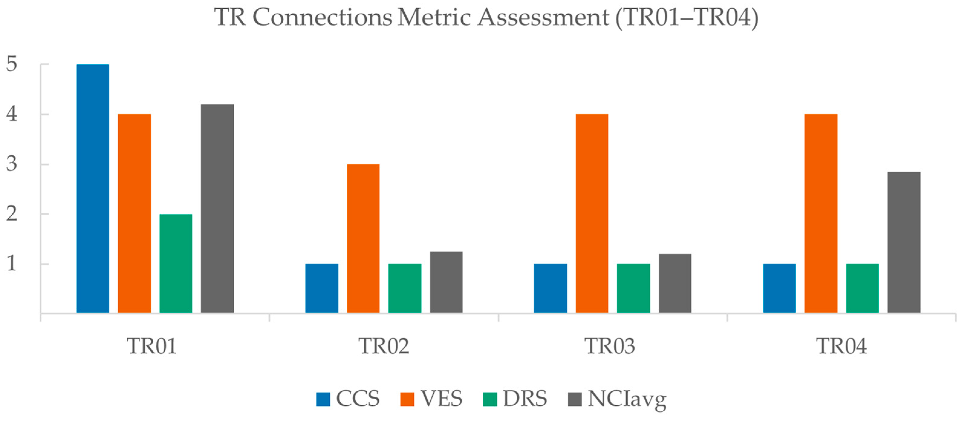
| TR01 | 5 | 4 | 2 | 0.84 |
| TR02 | 1 | 3 | 1 | 0.25 |
| TR03 | 1 | 4 | 1 | 0.24 |
| TR04 | 1 | 4 | 1 | 0.57 |
| Connection ID | CCS | VES | DRS | NCIavg |
|---|---|---|---|---|
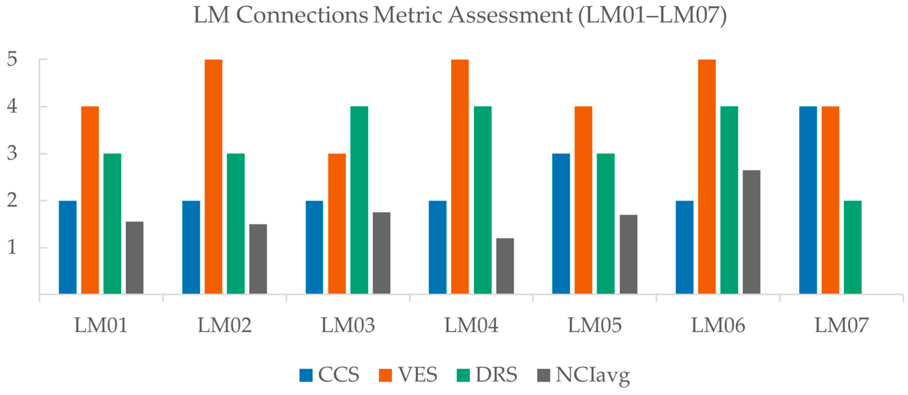
| LM01 | 2 | 4 | 3 | 0.31 |
| LM02 | 2 | 5 | 3 | 0.30 |
| LM03 | 2 | 3 | 4 | 0.35 |
| LM04 | 2 | 5 | 4 | 0.24 |
| LM05 | 4 | 4 | 3 | 0.34 |
| LM06 | 2 | 5 | 4 | 0.53 |
| LM07 | 4 | 4 | 2 | - |
| Connection ID | CCS | VES | DRS | NCIavg |
|---|---|---|---|---|
| DB01 | 5 | 2 | 4 | 0.13 |
| DB02 | 2 | 4 | 4 | - |
| DB03 | 2 | 2 | 3 | 0.35 |
| DB04 | 4 | 5 | 2 | 0.37 |
| DB05 | 3 | 4 | 3 | 0.74 |
| DB06 | 4 | 4 | 2 | - |
| DB07 | 4 | 2 | 2 | 1.00 |
| DB08 | 4 | 4 | 2 | 0.22 |
| DB09 | 3 | 4 | 4 | 0.64 |
| DB10 | 1 | 3 | 4 | 0.18 |
| DB11 | 2 | 4 | 3 | 0.61 |
| DB12 | 3 | 5 | 3 | 1.00 |
| DB13 | 4 | 5 | 2 | - |
| DB14 | 2 | 3 | 3 | 0.75 |
| DB15 | 4 | 3 | 4 | 0.49 |
| DB16 | 4 | 4 | 2 | 0.54 |
| DB17 | 2 | 4 | 2 | 0.61 |
| DB18 | 2 | 5 | 2 | 0.55 |
| DB19 | 2 | 4 | 2 | 0.78 |
| DB20 | 2 | 4 | 2 | 0.20 |
| DB21 | 2 | 5 | 2 | 0.06 |
| DB22 | 2 | 2 | 2 | 0.46 |
| Connection ID | CCS | VES | DRS | NCIavg |
|---|---|---|---|---|
| PB01 | 5 | 4 | 4 | 0.72 |
| PB02 | 3 | 3 | 3 | 0.13 |
| PB03 | 4 | 2 | 4 | 0.19 |
| PB04 | 4 | 4 | 3 | 0.28 |
| PB05 | 4 | 4 | 4 | 0.57 |
| PB06 | 4 | 4 | 4 | 0.79 |
| PB07 | 4 | 4 | 3 | 0.18 |
| PB08 | 4 | 4 | 4 | 0.26 |
| PB09 | 2 | 5 | 2 | 0.48 |
| PB10 | 4 | 3 | 4 | 0.52 |
| PB11 | 2 | 5 | 2 | 0.25 |
| PB12 | 4 | 2 | 3 | 0.79 |
| PB13 | 4 | 4 | 4 | 0.85 |
| PB14 | 2 | 4 | 3 | - |
| Connection Type | Avg CCS | Avg VES | Avg DRS | Avg NCIavg | Total Avg (Out of 20) | Comment |
|---|---|---|---|---|---|---|
| Tie-Rod (TR) | 2.0 | 3.8 | 1.25 | 0.48 | 9.45 | Poor composite compatibility and very limited demountability |
| Locking Mechanism (LM) | 2.4 | 4.3 | 3.3 | 0.35 | 11.65 | Strong validation and demountability; weaker composite suitability and lower NCIavg |
| Direct Bolted (DB) | 2.9 | 3.7 | 2.7 | 0.51 | 11.85 | Broad range in performance; highest NCIavg averages |
| Plug-Assisted Bolted (PB) | 3.6 | 3.7 | 3.3 | 0.46 | 12.91 | Highest overall average connection type |
Disclaimer/Publisher’s Note: The statements, opinions and data contained in all publications are solely those of the individual author(s) and contributor(s) and not of MDPI and/or the editor(s). MDPI and/or the editor(s) disclaim responsibility for any injury to people or property resulting from any ideas, methods, instructions or products referred to in the content. |
© 2026 by the authors. Licensee MDPI, Basel, Switzerland. This article is an open access article distributed under the terms and conditions of the Creative Commons Attribution (CC BY) license.
Share and Cite
Alotaibi, A.; Al Abadi, H.; Patel, V.I. Evaluation Framework for Inter-Module Connections in Steel–Concrete Composite Modular Structures. Buildings 2026, 16, 431. https://doi.org/10.3390/buildings16020431
Alotaibi A, Al Abadi H, Patel VI. Evaluation Framework for Inter-Module Connections in Steel–Concrete Composite Modular Structures. Buildings. 2026; 16(2):431. https://doi.org/10.3390/buildings16020431
Chicago/Turabian StyleAlotaibi, Abdulelah, Haider Al Abadi, and Vipulkumar Ishvarbhai Patel. 2026. "Evaluation Framework for Inter-Module Connections in Steel–Concrete Composite Modular Structures" Buildings 16, no. 2: 431. https://doi.org/10.3390/buildings16020431
APA StyleAlotaibi, A., Al Abadi, H., & Patel, V. I. (2026). Evaluation Framework for Inter-Module Connections in Steel–Concrete Composite Modular Structures. Buildings, 16(2), 431. https://doi.org/10.3390/buildings16020431