Abstract
The joint represents a critical component in precast concrete segmental bridges (PCSBs), playing an essential role in transferring shear stress. The efficacy of steel shear keys in comparison to conventional concrete tooth keys has been proven in terms of their shear transfer capability. In this study, a novel design using ultra-high-performance concrete (UHPC) to replace conventional concrete around the steel shear keys was proposed. A 30 m span precast concrete segmental T-girder with epoxy steel shear-keyed joints was fabricated to evaluate the effectiveness of the joint system. Experimental measurements included crack development, load–deflection response, and strain distribution. Furthermore, a finite element (FE) model was developed and validated with the experimental results. The results indicate that the epoxy steel shear-keyed joints effectively transmitted shear stress between segments, with the girder achieving an ultimate load of 1750 kN and a ductile flexural failure mode. The validated FE model accurately captured the critical characteristics of the structure. Finally, an effective calculation method was introduced to predict the ultimate load.
1. Introduction
Precast concrete girders have been widely used in bridge construction due to the advantages of industrial production and rapid construction [1,2,3]. However, their large size and heavy weight always result in transportation challenges, especially in mountainous regions, islands, and remote areas. Precast concrete segmental bridges (PCSBs) offer a viable solution to these constraints by dividing the monolithic girders into several segments, which are finally joined on-site. As this approach would result in the discontinuity of the reinforcements, a key design is a reliable and effective joint to ensure efficient shear transfer between segments [4,5].
According to the bonding method, there are three types of segment joints: a cast-in-place reinforced joint (wet joint), a dry joint, and an epoxy joint [6,7,8]. Experimental studies revealed that the spliced girder specimens with a wet joint showed comparable shear behavior to that of monolithic girders due to the continuity between the precast segments and the splice regions [9]. Nevertheless, the other two types of joints are more attractive due to the low cost and rapid construction speed [10,11]. It was demonstrated that epoxy joints resulted in enhanced cracking and ultimate load capacity of the segmental girder compared to dry joints, owing to the added tensile strength within the joint region [12]. Meanwhile, dry joints typically fail at the joint interface with noticeable joint opening, while cracks were found to originate from the concrete near the interface in epoxy circumstances [13,14]. Shear failure in dry joints is more brittle compared to the ductile manner shown in epoxy joints [3,15]. Despite these advantages, the dry jointed girder remains favored in certain instances due to its simplicity. The curing process of the epoxy at the joints is time-consuming and influenced by weather conditions, which can limit use [16,17]. Joints could also be classified by geometry as flat or keyed, with keyed joints further distinguished as single or multiple keys. Studies showed that epoxy multi-key joints exhibit more uniform stress across key teeth than dry multi-key joints [18]. The results of full-scale 12 m span rectangular girders under static loading showed that the ultimate load of the segmental girders with multi-keys, a single key, and a plain key was similar to that of monolithic girders. The multi-keyed girder demonstrated the smallest reduction of only 1.6% of the ultimate load. The joint key size was found to be related to the shear capacity of the joint. Shear capability improves with increasing size [19] and depth, but decreases with greater key spacing [20]. The use of U-bars inside keys could enhance shear strength, while post-tensioned tendons crossing the interface provide an even greater increase [20].
The behavior of segmental structures under complex loading conditions like combined bending, shear, and torsion was also studied. Turmo et al. (2006) [21] found that in dry-jointed segmental beams under shear and bending, cracks first formed at the joints and propagated toward the loading point. Li et al. (2013) [13] tested dry and epoxied joints under bending, combined shear-bending, and direct shear. Simplified failure modes and formulas were derived to predict joint resistance under combined loading. Yuan et al. (2015) [22] studied the effect of tendon ratio and load type, noting that both factors influence tendon stress, joint opening width, and failure mode. Segmental structures were found to be more sensitive under complex loading conditions. Algorafi et al. (2010) [23] applied torsional forces at different eccentricities and found that torsion reduces both vertical load capacity and deflection. Zhang et al. (2022) [24] reported that cyclic loading significantly reduced ultimate load capacity and stiffness compared to monotonic loading due to damage accumulation. When the contact area of the key was equal, specimens with one large key and those with multiple small keys showed similar bearing capacity and ductility under repeated loading.
Nowadays, much effort has been made to investigate the application of new materials in the joint, such as steel fiber-reinforced concrete (SFRC) [25], rapid hardening high-performance concrete (RHHPC) [26], reactive power concrete (RPC) [27], and UHPC [28,29]. These are always useful to improve the overall performance of the joint compared to normal concrete [24]. On the other hand, novel designs have also been developed, such as the prestressed bolted hybrid joint proposed by Zhang et al. (2020) [30]; the steel shear connectors (keys) proposed by Kim et al. (2008) [31] and Zou et al. (2022, 2022, 2024) [15,32,33] and Duanmu et al. [34]; and nut bolted shear connectors proposed by Luo et al. (2025) [35]. These new forms of keys were always in a simpler joint form or higher shear strength than conventional concrete tooth keys.
In summary, many studies have investigated the factors affecting the shear strength of the joint and the overall performance of the precast segmental girder, mainly focusing on the traditional concrete tooth key. Steel shear keys offer potential advantages for segmental girder construction by simplifying joint geometry and improving production efficiency, as they eliminate the need for casting intricate concrete teeth. A limitation of the current steel key design is that the keys are embedded in conventional concrete, which remains prone to cracking and crushing under high stress concentrations around the key regions. Furthermore, most previous investigations adopted direct shear tests on keys [15,24,31] or bending-shear tests on scale models [33], and reliable evidence for real-world applications is still rare. It is necessary to perform full-scale capacity testing to assess the true structural behavior and validate bridge design adequacy [36,37]. Although Kim et al. (2008) [31] conducted a notable full-scale study, their work focused on box girders with steel keys, leaving the ultimate flexural and shear behavior of full-scale T-girders with steel keys unexamined. In view of this, a novel design strategy was proposed for the first time by applying UHPC to replace the surrounding concrete of steel shear keys to resist local stress concentration. A full-scale 30 m span precast concrete segmental T-girder with epoxy steel shear-keyed joints was built. The research strategy employed a primary experimental investigation of the girder tested to failure, which served as the foundational baseline. Test variables included internal strains, deflections, joint displacements, neutral axis position, and crack patterns. This was complemented by a validated finite element analysis, which was used as a tool to further understand the mechanism of the system behavior. Finally, the shear and bending resistance calculation method of the segmental T-girder with steel shear keys was introduced.
2. Experimental Program
2.1. Specimen Design
As shown in Figure 1, the entire girder was symmetrical about its center line. It was divided into three segments: two side segments measured 9000 mm in theoretical length with a 40 mm expansion joint at the end, while the middle segment measured 12,000 mm in length.
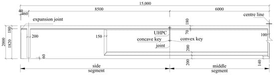
Figure 1.
Geometrical details of the segmental T-girder (unit: mm).
As demonstrated in Figure 2, the cross-sectional dimensions of the girders were as follows: 1740 mm in top flange width, 500 mm in bottom flange width, and 2000 mm in height. The top flange thickness was 180 mm, and the web width was 220 mm. The reinforcement layout comprised six 25 mm diameter steel bars in the bottom flange, 10 mm diameter bars in the web, and 12 mm diameter bars in the top flange. Additionally, 12 mm four-leg stirrups and double-leg stirrups were positioned in the web for sections A-A and B-B, respectively.
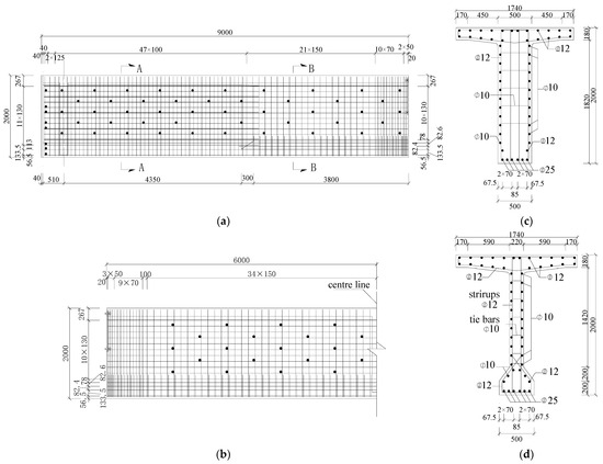
Figure 2.
Reinforcement layout (unit: mm): (a) side segment; (b) middle segment; (c) section A-A; (d) section B-B.
Three prestressing tendons (N1–N3) were positioned along the girder, as illustrated in Figure 3. N1 consists of 11 strands, while N2 and N3 consist of 10. Each strand was 15.2 mm in diameter, and the section area was 140 mm2.
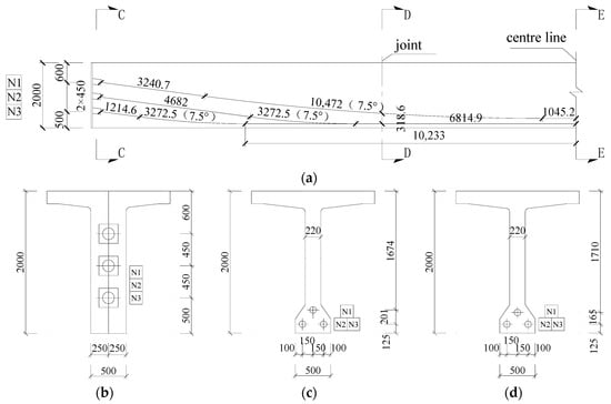
Figure 3.
Prestressing tendon layout (unit: mm): (a) main view; (b) section C-C; (c) section D-D; (d) section E-E.
The design of the steel shear keys used in this study was similar to that described in Zou et al.’s (2024) study [33], as shown in Figure 4.
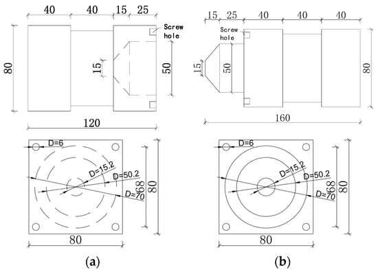
Figure 4.
Design of steel shear keys (unit: mm): (a) concave key; (b) convex key.
In practical applications, steel shear keys were found to be challenging to install and prone to disruption during the concrete pouring process. Additionally, stress concentration in the surrounding concrete of the keys is more significant, since the steel shear keys are smaller than conventional concrete tooth keys. To facilitate optimal load transfer and reduce the risk of local damage, UHPC was used to replace the surrounding concrete. Pairs of UHPC plates were cast first to fix the position of shear keys, as shown in Figure 5. Each pair included two plates: one inserted with convex keys and the other with concave keys. During fabrication, the bottom formworks for each pair of UHPC plates were meticulously aligned to ensure precise dimensional compatibility. Initially, three steel shear keys (concave keys, for example) were fixed to the formwork of a single UHPC plate using screws. Anchor reinforcements were placed in position for anchoring, followed by pouring UHPC into the formwork. After a curing period of seven days, the UHPC plate was removed from the formwork and fixed to the side formwork of the segment, as shown in Figure 5c.
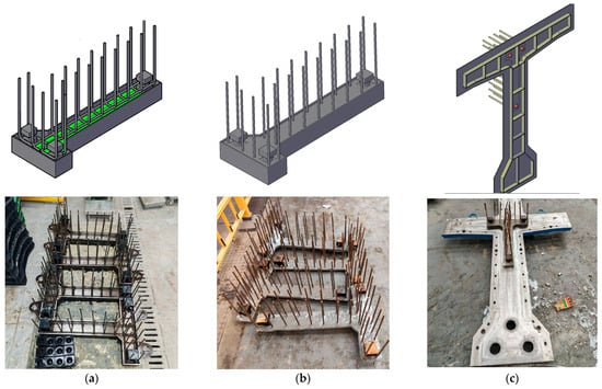
Figure 5.
Casting and fixing procedure of UHPC plates: (a) fixing of steel shear keys and anchor reinforcements; (b) pouring process of UHPC plates; and (c) fixing of the UHPC plates.
The UHPC plate with concave keys was employed in the side segment, while the plate with convex keys was employed in the middle segment. The geometry and placement of the plates are illustrated in Figure 6. Each UHPC plate has a thickness of 40 mm, which was chosen to properly embed the load-bearing end section of the keys. This design could ensure that the primary shear force is effectively transferred through the load-bearing end of the keys to the surrounding UHPC, creating an efficient and robust load path. Additionally, the alignment of the UHPC plates during the pouring process allowed greater precision in the segments connecting on-site.
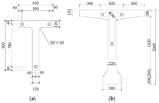
Figure 6.
Joint layout (unit: mm): (a) geometry of UHPC plate; (b) location of the UHPC plate.
The segments were bonded together using a structural epoxy. Prior to bonding, the segments were then positioned and aligned. The connecting surfaces of the segments were cleaned by high-pressure water jetting to remove any contaminants and slurry. A two-component epoxy, mixed in a ratio of 2:1 by weight for Components A and B, was mechanically mixed until uniform. The epoxy was then applied to both contact surfaces at an ambient temperature of approximately 25–30 °C. The epoxy was spread uniformly using a trowel to a thickness of 1–2 mm on each surface. About 1–3 mL of epoxy was used to form a thin layer on the surface of each key. The segments were then connected within 45 min. During assembly, prestressing tendons were tensioned to 50% of the control stress (697.5 MPa) to apply consolidation pressure. The joint was then allowed to cure under this initial stress at ambient environment for twelve hours before the prestressing was completed to the control stress of 1395 MPa.
2.2. Material Properties
Ready-mixed concrete was used in casting the girder. During the casting of the girder, three 150 mm × 150 mm × 150 mm cubes were reserved with the same curing conditions as the segmental girder. In accordance with GB/T 50081-2019 [38], the cubes were tested under monotonic loading until failure. The average cubic compressive strength of the concrete fcu was 74.6 MPa. The UHPC was the commercially available T120 supplied by Zhejiang TENACAL Co., Ltd., Ningbo, China, which contains 2% by volume of straight steel fibers. According to the manufacturer’s specifications, the fibers have a nominal length of 13 mm and a diameter of 0.22 mm. The compressive strength and tensile strength of UHPC were 120 MPa and 7 MPa, respectively. HPB300 and HRB400 reinforcements were employed as shown in Figure 3. High-strength, low-relaxation steel strands were utilized for prestressing tendons. Properties of the reinforcements and steel strands were evaluated by a uniaxial test following the standard GB/T 228.1-2021 [39]. Three samples were tested, and the average value was used, as listed in Table 1. The epoxy used for the joints was JN-P, which is manufactured by Hunan GOOD BOND Co., Ltd., Changsha, China. According to the manufacturer’s specifications, it has a compressive strength of 94 MPa, an elastic modulus of 7.8 GPa, and a tensile shear strength of 20.0 MPa between two steel plates.

Table 1.
Properties of reinforcements and steel strand.
2.3. Testing Apparatus
The test loading was performed using two 200-ton hydraulic jacks, arranged as demonstrated in Figure 7a. Each jack was connected to the prestressed concrete reaction frame at the bottom via a distribution beam using two ϕ75 mm threaded steel bars. The synchronized pressure application of two jacks was achieved through the utilization of a single oil pump. As shown in Figure 7b, linear variable displacement transducers (LVDTs) were mounted at the middle D2, loading D1 (D3) and support Z1 (Z2) sections, respectively, to record the corresponding displacement. The labels in brackets represented the sections on the other side of the girder. In order to measure the strain response, strain gauges were glued to the surface of the concrete 80 mm away from the middle section S1 and the joint section S2 (S3). Additionally, extra strain gauges were affixed across joint section S2 (S3). The sectional layout of strain gauges is indicated in Figure 8.
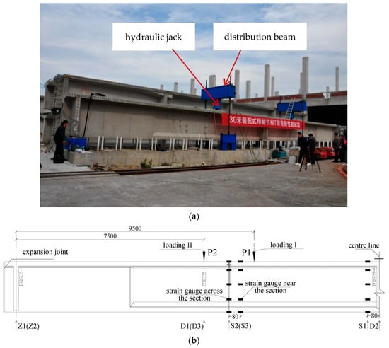
Figure 7.
Full-scale test of the segmental T girder (unit: mm): (a) test set-up; (b) loading layout.
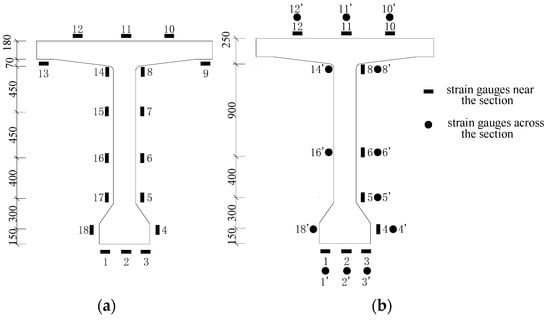
Figure 8.
Strain gauges layout (unit: mm): (a) section S1; (b) section S2 (S3).
To evaluate the mechanical behavior of the precast concrete segmental T-girder, a full-scale test was conducted with two loading conditions, as shown in Figure 7b. In the first loading condition, two hydraulic jacks were located 1000 mm inside the joints with a shear span of 9500 mm (loading I). The specimen was loaded to 400 kN (per hydraulic jack) and unloaded to 0 kN to examine the performance of the specimen, especially the response of the joints under design shear-bending load. In the second loading condition, two hydraulic jacks were moved to 1000 mm outside the joints with a shear span of 7500 mm (loading II). Then the specimen was loaded until failure or large displacement to examine the performance of the specimen and joints under bending load. A graded load of 100 kN was to be applied at each level with a pause of 10 min for the cracks to develop after the initiation of the first crack. The specimen surface was marked with a grid measuring 200 × 200 mm, and the development of cracks on the girders was carefully recorded during the process.
3. Experimental Results
The load value described in this test refers to the force exerted by one hydraulic jack. During the loading process I, no cracks were observed in the segmental T-girder and the structure operated under linear elastic conditions. The joint exhibited satisfactory performance characteristics under design shear-bending load. Therefore, only the test results during the loading process II are described and discussed in the following paragraphs.
3.1. Crack and Failure Pattern
The crack distributions of the segmental T-girder during loading process II are illustrated in Figure 9. The first vertical crack was visually observed at the bottom of both joints at a load of 1000 kN, defined as the visual cracking load, Pvcr. It should be noted that the actual cracking load is prior to the visual cracking load. This initiation at the joints is a direct result of the discontinuity in longitudinal reinforcement, which creates a weak plane where tensile stress concentrates under bending. As the load increased to 1200 kN, multiple cracks appeared at the bottom of the beams in the mid-span area, with some cracks extending toward the web. The crack at the joint propagated to the location of the UHPC plate with a height of 1180 mm, and diagonal cracks were visible in the structure. The development of cracks under constant load signifies the degradation of the joint interface. At the ultimate load Pu of 1750 kN, the girder exhibited significant deformation with a mid-span displacement exceeding 140 mm. Cracks extended to a height of 1525 mm in the mid-span web and 1650 mm at the joint, respectively. The critical failure was characterized by a dominant vertical crack at the joint interface, where the crack width, conservatively assessed with a steel ruler, exceeded 3 mm. This crack was wider than any flexural crack found in the mid-span, indicating that the joint interface was the critical region governing the ultimate flexural capacity. The primary failure mode showed that despite the enhanced shear capacity provided by the steel shear keys and UHPC replacement, the joint interface remained the limiting factor of the system.
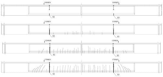
Figure 9.
Crack distributions of the segmental T-girder (Loading II).
3.2. Load-Strain Response
As the strain gauges were glued to the surface of the concrete after the process of prestressing, the recorded values represented strain increments rather than actual strain values. Typical load-strain responses of the segmental T-girder during the loading process II are illustrated in Figure 10. The same color line represents the strain increment at the same height but on a different side of the section. The solid line and dashed line represent the strain increment near the section and across the section, respectively. Before the initiation of the first crack at the joint, concrete strain increased proportionally with loading force. As the load increases, inflection points are initiated, denoting the emergence of cracks. Additionally, due to the formation of the crack at the joint, the response of the strain gauges across the joint typically exhibits a more pronounced effect than that near the joint, as shown in Figure 10b.
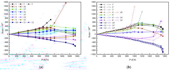
Figure 10.
Typical load-strain responses of the segmental T-girder: (a) section S1; (b) section S2.
The distributed strain responses along the beam height are illustrated in Figure 11. The strain distribution remained largely linear and stable up to a load of approximately 1000 kN for section S1, still conforming to the plane-section assumption. As for section S2, this maximum load was 900 kN. Moreover, the strain distributions across the section and near the section showed little difference at the bottom, which could indicate the initial formation of micro-cracks between these two sections at the bottom. Combined with the visual cracking load of 1000 kN, the actual analytical cracking load Pcr was estimated to be 900 kN to 1000 kN. The height of the neutral axis of the cross-section at sections S1 and S2 is approximately 1250 mm and 1200 mm, respectively. As demonstrated in Figure 11b, the dashed line coincides with the solid line at the same level of load, indicating that the joint could provide effective load transfer before cracking.
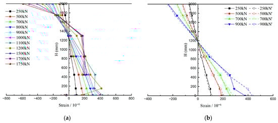
Figure 11.
The strain responses along the height of the segmental T-girder: (a) section S1; (b) section S2.
3.3. Load Displacement Relationship
The load displacement relationships of the middle section and loading section are shown in Figure 12. The segmental girder experienced three typical stages. The initial stage was characterized by an elastic response, whereby displacement exhibited a direct proportionality with applied load. As recorded, although the joints began to crack at 1000 kN, the overall segmental girder retained its initial stiffness until 1100 kN. The initial stiffness, calculated as the slope of the linear elastic portion, was 29.3 kN/mm. To assess stiffness degradation after cracking, the secant stiffness was calculated at a load level of 1200 kN, representing 1.2 times the cracking load and stable post-cracking conditions. The secant stiffness at this level was 21.6 kN/mm, indicating a 26.3% reduction compared with the initial stiffness. However, the displacement increased almost linearly with the applied load after cracking until 1700 kN. This indicated that the segmental girder exhibited adequate ductility after the initiation of the crack at the joints. After that, tangent stiffness decreased again, indicating that the prestressing tendon came to an inelastic stage.
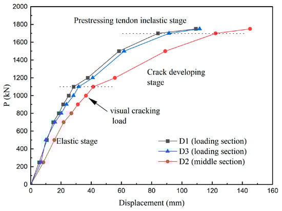
Figure 12.
The load–displacement relationship.
4. Finite Element Modeling and Validation
4.1. Numerical Model
Numerical simulation is an effective way to evaluate the crack propagation and parameter analysis [40]. A three-dimensional finite element model (FEM) was established in ABAQUS 2022 to simulate the structural response, as illustrated in Figure 13. The model properly replicated the test girder, including the three segments, the steel reinforcements, and the UHPC. The reinforcement was modeled as discontinuous at the joint sections, while the prestressing tendons were continuous, accurately reflecting the actual structural design. The steel shear keys were simplified and modeled as solid square cross-section elements of equivalent sectional area, despite their actual circular shape at the interface, to maintain computational efficiency while preserving their primary shear transfer function. The concrete, UHPC, and steel keys were modeled using 8-node reduced integration brick elements (C3D8R). The prestressing tendons and reinforcement were modeled using 2-node truss elements (T3D2). Two mesh sizes of 200 mm and 100 mm were used for the global model, with a refined mesh of 10 mm applied at the joint regions to ensure accuracy in critical areas.
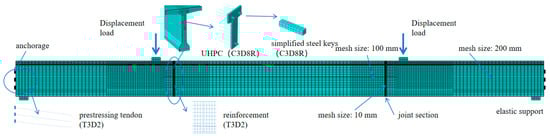
Figure 13.
Finite element model.
The prestressing tendons and reinforcement were embedded in the concrete mesh. A perfect bond between the reinforcement and the surrounding concrete mesh was assumed by this technique. In the steel shear-keyed joint, “Tie” constraint was used to simulate the interfaces between the segments, UHPC and concrete, the steel key and UHPC. This constraint is justified for this study as it perfectly bonds the surfaces, which is a reasonable simplification to represent the high-strength, rigid nature of the epoxy-bonded interfaces under serviceability limit states. This approach allows the model to focus on the global flexural response and the effect of the keys. Moreover, it effectively represents expected failure mode while significantly reducing computational cost by avoiding the convergence difficulties associated with modeling complex contact nonlinearities at all interfaces.
4.2. Material Properties and Constitutive Models
The material parameters are listed in Table 2. The constitutive relationships of the materials are illustrated in Figure 14. The double line model was used for both reinforcement and prestressing tendons. The concrete damaged plasticity model was used for both normal concrete and UHPC. This model has been widely used in ABAQUS analysis [41,42,43]. The stress–strain relationship specified in the Chinese GB 50010 [44] was used to define the behavior of normal concrete. The model summarized by Guan [45] was used to define the behavior of UHPC. The compression and tension damage parameters were then obtained by the following equation [46]:
Table 2.
Parameters of the materials for modeling.
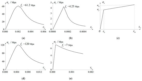
Figure 14.
Constitutive relationships: (a) compression of concrete; (b) tension of concrete; (c) reinforcement and prestressing tendon; (d) compression of UHPC; (e) tension of UHPC.
Here, E0 represents the initial elastic modulus value. The prestress force was introduced to the tendons by the initial temperature method. The total prestress losses were estimated as 230 MPa according to empirical data, and the initial effective prestress force was set as 1165 MPa.
4.3. Model Validation
Verification was conducted by comparing the predictions with the experimental results. The failure status of the girder is illustrated in Figure 15. The failure mode, which formed a dominant vertical crack along the joint interface, was consistent with the experimental observation, and the prestressing tendons were found to have reached their tensile strength at the joint section. It can be concluded that using the joint section as the control section for calculating was reasonable.
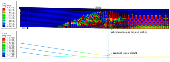
Figure 15.
Status of the concrete and prestressing tendons at ultimate load.
The displacement curve of the middle section was compared with the experimental results in Figure 16. During the initial elastic stage, the relationship of FEM showed a good consistency with the experimental curve, while the tangent slope of the model decreased more than the experimental results during the crack development stage. This discrepancy may be due to several reasons. First, the constitutive model for concrete is ideal, which cannot adequately reflect the interlocking and friction effect after cracking, especially in the joint region. Another reason may be the use of “Tie” constraints for the epoxy-bonded interfaces. Though it can predict the pre-cracking global response and the final state after loading, it may fail to reflect the debonding process precisely.
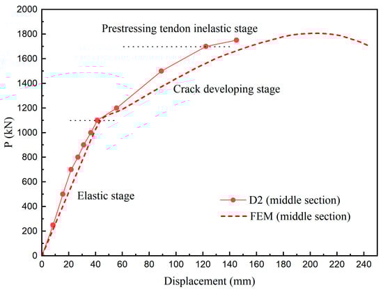
Figure 16.
Comparison between the load–displacement relationship of EXP. and FEM.
Key response values are also summarized in Table 3. The experimental initial stiffness was 29.3 kN/mm, while the FEM monitored 25.7 kN/mm, indicating a 12% difference. The reason may be that the elastic modulus of concrete was slightly underestimated in the simulation. The cracking load of FEM was larger than that of the experiment, with a maximum discrepancy of 13% when compared to a lower-bound estimate of the experimental cracking load. The reason may be that the idealization of the FE model failed to accurately simulate the very first micro-fracture in the concrete, which contained inherent microscopic flaws. On the other hand, the FEM showed close agreement with the visual cracking load. As for the deflection at ultimate load, the predicted value of FEM is notably larger than the experimental result. The main reason is that the test was terminated by a large displacement with a small load increment, while the FEM predicted the total failure reaching the tensile strength of prestressing tendons. The deflection of the experimental girder could still increase under loading.
Table 3.
Comparison of experimental and FEM results.
Overall, the FEM can successfully capture the most critical structural characteristics and is considered validated for predicting the load-bearing capacity. It is an effective and simple method to use in engineering programs that focus more on the initial elastic stage and safety margin.
5. Calculation Method
5.1. Shear Capacity
The practical calculation formula for calculating the shear capacity Vs of steel shear keys is the following:
where n is the number of keys at the joint, which equals 3. τs is the allowable shear stress of the steel used in the shear key, which equals 213.6 MPa. As is the section area of the steel shear key across the joint, which equals 1963.5 mm2. The shear strength of three steel keys can be calculated as 1258 kN.
Vs = nτsAs
When the friction between the segments is considered, the joint shear capacity Vj can be expressed as follows:
where μ is the friction coefficient of concrete at the joint and equals 0.6 for a concrete-to-concrete interface that has not been intentionally roughened according to AASHTO [49]. σn is the normal compressive stress in concrete after prestressing loss and equals 6 MPa in this test. Aj is the area of the shear plane and equals 0.84 m2. Then the shear capacity of the joint, independent of the effect of the epoxy, can be calculated as 4291 kN, which is enough for shear resistance.
Vj = nτsAs + μAjσn
According to the improved empirical equation improved by Shamass et al. (2017) [50] from Buyukozturk et al. (1990) [51], when epoxy bonding is considered, the epoxy joint shear capacity Vj is expressed as follows:
where ft and fc are the tensile strength of concrete and compressive strength of concrete cylinder. σn is the normal compressive stress in concrete after prestressing loss and equals 6 MP. The predicted shear capacity was 10,269 kN.
Though epoxy has been demonstrated to substantially enhance the shear resistance of joints, the quality of epoxy adhesives is significantly impacted by the construction quality and natural environmental factors. From the perspective of structural safety and conservative design, the contribution of epoxy to shear resistance was not considered in practice.
5.2. Flexural Capacity
For the segmental girder, failure was governed by the joint section. In this circumstance, only the effect of the prestressing tendons needs to be considered. This assumption reflects the actual construction of the segmental girder, where the ordinary longitudinal reinforcements are discontinuous and terminate at the end surface of each segment. Based on the plane-section assumption and strain compatibility condition, the equilibrium equations of the joint section can be expressed as follows:
A comparison of the experimental and calculated values is listed in Table 4. The calculated ultimate load is 1786.5 kN, compared to the experimental value of 1750 kN, resulting in a 2% discrepancy. The predicted load is slightly bigger than the experimental value. One reason is that the tensile strength of the prestressing tendon is adopted in the calculation method, while the experimental ultimate load was defined as the load increasing slightly with large displacement. The little discrepancy shows that it is reasonable to calculate the ultimate load of the segmental girder by simply neglecting the contribution of reinforcements.
Table 4.
Comparison of experimental and calculated results.
6. Conclusions
The joint is a critical structural element in PCSBs, playing an essential role in shear transfer and significantly influencing the overall behavior of the girder. This study presented a comprehensive experimental and numerical investigation into the structural behavior of a full-scale 30 m-span precast concrete segmental T-girder with epoxy steel shear-keyed joints. A novel design using UHPC to replace the concrete surrounding the steel keys was proposed. The following conclusions can be drawn from the scope of this study:
- The proposed joint system was demonstrated to be an effective means of transferring shear stress between segments. The girder exhibited linear-elastic behavior up to a cracking load of 1000 kN, and the girder reached an ultimate load of 1750 kN. The safety margin is adequate for practice application.
- The dominant failure mode was characterized by a dominant vertical crack at the joint interface. Despite the enhanced shear capacity provided by the steel shear keys and UHPC replacement, the joint interface was still the weakest section of the whole girder. Attention must be paid to the arrangement of the prestressing tendons.
- A validated finite element model was developed, which accurately replicated the critical experimental response, including cracking load, ultimate load, and failure mode. This model provides a useful tool for primary design and future parametric studies.
- A simple calculation method was introduced by taking the joint section as the control section and neglecting the contribution of reinforcements. The accuracy of the method was verified by comparison between the experimental and predicted values.
It should also be noted that the results from this study were based on monotonic loadings. The in-service segmental bridges are often subjected to long-term cyclic loading by traffic, which affects the fatigue effect, fatigue accumulation and stiffness loss of the whole girder. The behavior of the segmental with epoxy steel shear-keyed joints under cyclic conditions should be studied further. A direct comparison with a geometrically identical monolithic girder is also recommended. This would allow for a direct quantification of the joint system’s specific impact on the overall structural performance based on the baseline established in this study.
Author Contributions
Conceptualization, H.S. and B.S.; methodology, H.S. and L.S.; investigation, H.S. and L.S.; resources, L.S. and S.Q.; data curation, H.S. and L.Q.; writing—original draft preparation, H.S. and L.Q.; writing—review and editing, H.S. and L.Q.; project administration, L.S. and S.Q.; funding acquisition, S.Q. and B.S. All authors have read and agreed to the published version of the manuscript.
Funding
This research was funded by Ningbo Communications Investment Group Co., Ltd. (grant no. 2025-ZGS-0001).
Data Availability Statement
The original contributions presented in this study are included in the article. Further inquiries can be directed to the corresponding author.
Acknowledgments
The authors acknowledge the Ningbo Municipal Transport Bureau for designating this study as a key scientific research project in 2024 and for providing essential institutional support. The authors also extend their gratitude to Dong Xu of Tongji University for his valuable contributions to discussions related to this research.
Conflicts of Interest
Authors Haifeng Shi, Liqi Qiu, Luocen Shen, Songli Qiu and Bingquan Song were employed by the company Ningbo Communications Engineering Construction Group Co., Ltd. All declare that the research was conducted in the absence of any commercial or financial relationships that could be construed as a potential conflict of interest. The sponsors had no role in the design, execution, interpretation, or writing of the study.
References
- Han, M.Y.; Jin, K.S.; Chang, D.H.; Kang, T.H.; Jeon, S.J. Effect of Holes and Segmentation on the Structural Behavior of a Prestressed Concrete Girder. KSCE J. Civ. Eng. 2014, 18, 1711–1719. [Google Scholar] [CrossRef]
- Culmo, M.P. Accelerated Bridge Construction—Experience in Design, Fabrication and Erection of Prefabricated Bridge Elements and Systems; Fhwa-Hif-12-013; Federal Highway Administration, Office of Bridge Technology: Washington, DC, USA, 2011. [Google Scholar]
- Ahmed, G.H.; Aziz, O.Q. Stresses, Deformations and Damages of Various Joints in Precast Concrete Segmental Box Girder Bridges Subjected to Direct Shear Loading. Eng. Struct. 2020, 206, 110151. [Google Scholar] [CrossRef]
- Ahmed, G.H.; Aziz, O.Q. Shear Strength of Joints in Precast Posttensioned Segmental Bridges during 1959–2019, Review and Analysis. Structures 2019, 20, 527–542. [Google Scholar] [CrossRef]
- Issa, M.A.; Abdalla, H.A. Structural Behavior of Single Key Joints in Precast Concrete Segmental Bridges. J. Bridge Eng. 2007, 12, 315–324. [Google Scholar] [CrossRef]
- Feng, Z.; Li, C.; Ke, L.; Yoo, D.Y. Experimental and Numerical Investigations on Flexural Performance of Ultra-High-Performance Concrete (UHPC) Beams with Wet Joints. Structures 2022, 45, 199–213. [Google Scholar] [CrossRef]
- Jiang, H.; Cao, Q.; Liu, A.; Wang, T.; Qiu, Y. Flexural Behavior of Precast Concrete Segmental Beams with Hybrid Tendons and Dry Joints. Constr. Build. Mater. 2016, 110, 1–7. [Google Scholar] [CrossRef]
- Zhang, Y.; Zhang, Z.; Hu, F.; Du, X.; Lu, Y.; Zhu, J. Full-Scale Experimental Study on Shear Behavior of Multiple-Keyed Epoxy Joints in Precast Concrete Segmental Bridges. Structures 2022, 45, 437–447. [Google Scholar] [CrossRef]
- Williams, C.S.; Moore, A.M.; Al-Tarafany, D.; Massey, J.B.; Bayrak, O.; Jirsa, J.O.; Ghannoum, W.M. Evaluation of Cast-in-Place Splice Regions of Spliced I-Girder Bridges. ACI Struct. J. 2019, 116, 181–193. [Google Scholar] [CrossRef]
- Duanmu, X.; Xu, D.; Qiu, T.; Zou, Y. Bending Behaviour of Precast Concrete Segmental Girders with Steel Rebars through Epoxy Joints. Structures 2024, 63, 106491. [Google Scholar] [CrossRef]
- Dongzhou Huang, B.H. Concrete Segmental Bridges Theory, Design, and Construction to AASHTO LRFD Specifications; CRC Press: Boca Raton, FL, USA, 2019; ISBN 9781119130536. [Google Scholar]
- Saibabu, S.; Srinivas, V.; Sasmal, S.; Lakshmanan, N.; Iyer, N.R. Performance Evaluation of Dry and Epoxy Jointed Segmental Prestressed Box Girders under Monotonic and Cyclic Loading. Constr. Build. Mater. 2013, 38, 931–940. [Google Scholar] [CrossRef]
- Li, G.; Yang, D.; Lei, Y. Combined Shear and Bending Behavior of Joints in Precast Concrete Segmental Beams with External Tendons. J. Bridge Eng. 2013, 18, 1042–1052. [Google Scholar] [CrossRef]
- Al-Sherrawi, M.H.; Allawi, A.A.; AL-Bayati, B.H.; Al Gharawi, M.; El-Zohairy, A. Behavior of Precast Prestressed Concrete Segmental Beams. Civ. Eng. J. 2018, 4, 488–496. [Google Scholar] [CrossRef]
- Zou, Y.; Xu, D. Experimental Study on Shear Behavior of Joints in Precast Concrete Segmental Bridges. Structures 2022, 39, 323–336. [Google Scholar] [CrossRef]
- Yuan, A.; Dai, H.; Sun, D.; Cai, J. Behaviors of Segmental Concrete Box Beams with Internal Tendons and External Tendons under Bending. Eng. Struct. 2013, 48, 623–634. [Google Scholar] [CrossRef]
- Chai, S.; Guo, T.; Chen, Z.; Yang, J. Monitoring and Simulation of Long-Term Performance of Precast Concrete Segmental Box Girders with Dry Joints. J. Bridge Eng. 2019, 24, 04019043. [Google Scholar] [CrossRef]
- Zhou, X.; Mickleborough, N.; Li, Z. Shear Strength of Joints in Precast Concrete Segmental Bridges. ACI Struct. J. 2005, 102, 3–11. [Google Scholar] [CrossRef]
- Li, S.; Casas, J.R.; Chen, X.; Sun, Y.; Liu, D. Experimental Study on the Failure Process of Large Shear Key Joints Based on NDT Methods. Ce/Papers 2023, 6, 1167–1173. [Google Scholar] [CrossRef]
- Yuan, A.; Yang, C.; Wang, J.; Chen, L.; Lu, R. Shear Behavior of Epoxy Resin Joints in Precast Concrete Segmental Bridges. J. Bridge Eng. 2019, 24, 04019009. [Google Scholar] [CrossRef]
- Turmo, J.; Ramos, G.; Aparicio, Á.C. Shear Behavior of Unbonded Post-Tensioned Segmental Beams with Dry Joints. ACI Struct. J. 2006, 103, 409–417. [Google Scholar] [CrossRef]
- Yuan, A.; He, Y.; Dai, H.; Cheng, L. Experimental Study of Precast Segmental Bridge Box Girders with External Unbonded and Internal Bonded Posttensioning under Monotonic Vertical Loading. J. Bridge Eng. 2015, 20, 04014075. [Google Scholar] [CrossRef]
- Algorafi, M.A.; Ali, A.A.A.; Othman, I.; Jaafar, M.S.; Anwar, M.P. Experimental Study of Externally Prestressed Segmental Beam under Torsion. Eng. Struct. 2010, 32, 3528–3538. [Google Scholar] [CrossRef]
- Zhang, Y.; Li, Z.; Chen, Z.; Shao, J.; Yue, F.; Liu, F.; John Ma, Z. Experimental and Numerical Investigations on Shear Performance of Key Tooth Joints of Precast Concrete Segmental Bridge under Repeated Loading. Constr. Build. Mater. 2022, 351, 128794. [Google Scholar] [CrossRef]
- Jiang, H.; Wei, R.; John Ma, Z.; Li, Y.; Jing, Y. Shear Strength of Steel Fiber-Reinforced Concrete Dry Joints in Precast Segmental Bridges. J. Bridge Eng. 2016, 21, 04016085. [Google Scholar] [CrossRef]
- Jiang, H.; Chen, Z.; Fang, Z.; Fang, S.; Tu, W.; Mo, F.; Xie, S.; Liu, J. Rapid Hardening High Performance Concrete (RHHPC) for Bridge Expansion Joints: From Material Properties to Interfacial Shear Performance. Constr. Build. Mater. 2025, 458, 139638. [Google Scholar] [CrossRef]
- Jiang, H.; Huang, C.; Feng, J.; Gao, X.; Wang, T.; Zhong, Z. Direct Shear Behavior of Castellated Dry RPC Joints in Precast Concrete Segmental Bridges. Structures 2021, 33, 4579–4595. [Google Scholar] [CrossRef]
- Voo, Y.L.; Foster, S.J.; Voo, C.C. Ultrahigh-Performance Concrete Segmental Bridge Technology: Toward Sustainable Bridge Construction. J. Bridge Eng. 2015, 20, B5014001. [Google Scholar] [CrossRef]
- Liu, T.; Wang, Z.; Guo, J.; Wang, J. Shear Strength of Dry Joints in Precast UHPC Segmental Bridges: Experimental and Theoretical Research. J. Bridge Eng. 2019, 24, 04018100. [Google Scholar] [CrossRef]
- Zhang, Y.; Zhu, P.; Shi, J. Flexural Behavior of Precast UHPC Beam with Prestressed Bolted Hybrid Joint. Eng. Struct. 2020, 206, 110100. [Google Scholar] [CrossRef]
- Kim, J.; Chung, W.; Jay Kim, J.H. Experimental Investigation on Behavior of a Spliced PSC Girder with Precast Box Segments. Eng. Struct. 2008, 30, 3295–3304. [Google Scholar] [CrossRef]
- Zou, Y.; Xu, D. Shear Behavior of Steel Keyed Joints in Precast Concrete Segmental Bridges under Direct Shear Loading. Struct. Concr. 2022, 23, 2710–2731. [Google Scholar] [CrossRef]
- Zou, Y.; Xu, D.; Duanmu, X. Tests and Calculation Methods for the Shear Performance of Steel Shear Keyed Joint Segment Beams. Arch. Civ. Mech. Eng. 2024, 24, 128. [Google Scholar] [CrossRef]
- Duanmu, X.; Xu, D.; Zhang, P.; Tang, G.; Liu, C. Experimental and Numerical Analysis on Tri-Segment T-Girders with Different Joint Types. Eng. Fail. Anal. 2025, 173, 109430. [Google Scholar] [CrossRef]
- Luo, J.; Wu, G.; Zhao, G.; Ma, Y.; Fang, Z.; Fang, S. Experimental and Numerical Analysis on Shear Performance of Single Embedded Nut Bolted Shear Connectors in Prefabricated Steel-UHPC Composite Structures under Cyclic Loading. Structures 2025, 73, 108446. [Google Scholar] [CrossRef]
- Zhou, C.; Wu, S.; Wu, K.; Mo, F.; Jiang, H.; Tian, Y.; Fang, J. Experimental and Numerical Investigation on Flexural Behaviors of a 30 m Full-Scale Prestressed UHPC-NC Composite Box Girder. Buildings 2025, 15, 3089. [Google Scholar] [CrossRef]
- Tu, W.; Cheng, Q.; Zhang, L.; Li, P.; Jiang, H.; Tian, Y.; Fang, J. Shear Performance of 25 m Full-Scale Prestressed UHPC-NC Composite I-Beam without Stirrups. Case Stud. Constr. Mater. 2024, 21, e03942. [Google Scholar] [CrossRef]
- GB/T 50081-2019; Standard for Test Method of Mechanical Properties on Ordinary Concrete. China Architecture & Building Press: Beijing, China, 2019.
- GB/T 228.1-2021; Metallic Materials-Tensile Testing-Part 1: Method of Test at Room Temperature. China Architecture & Building Press: Beijing, China, 2021.
- Chen, F.; Liu, X.; Zhang, H.; Luo, Y.; Lu, N.; Liu, Y.; Xiao, X. Assessment of Fatigue Crack Propagation and Lifetime of Double-Sided U-Rib Welds Considering Welding Residual Stress Relaxation. Ocean. Eng. 2025, 332, 121400. [Google Scholar] [CrossRef]
- Aksoylu, C.; Özkılıç, Y.O.; Çeledir, E.; Arslan, M.H. Bending Performance of Dapped-End Beams Having Web Opening: Experimental and Numerical Investigation. Structures 2023, 48, 736–753. [Google Scholar] [CrossRef]
- Aksoylu, C.; Özkılıç, Y.O.; Çeledir, E.; Başaran, B.; Arslan, M.H. Experimental and Numerical Investigation of Bending Performance of Prestressed Purlins Having Different Longitudinal Web Opening. Structures 2024, 60, 105839. [Google Scholar] [CrossRef]
- Aksoylu, C.; Özkılıç, Y.O.; Arslan, M.H. Damages on Prefabricated Concrete Dapped-End Purlins Due to Snow Loads and a Novel Reinforcement Detail. Eng. Struct. 2020, 225, 111225. [Google Scholar] [CrossRef]
- GB50010-2010; Code for Design of Concrete Structures. China Architecture & Building Press: Beijing, China, 2010.
- Guan, P.; Tu, Y.; Zhang, P.; Tang, G. A Review on Constitutive Relationship of Ultra-High-Performance Concrete under Uniaxial Compression and Tension. Fuhe Cailiao Xuebao/Acta Mater. Compos. Sin. 2019, 36, 1295–1305. [Google Scholar] [CrossRef]
- Sidoroff, F. Description of Anisotropic Damage Application to Elasticity. In Proceedings of the Physical Non-Linearities in Structural Analysis, Senlis, France, 27–30 May 1980; pp. 237–244. [Google Scholar]
- Yu, Z.; Ding, F. Unified Calculation Method of Compressive Mechanical Properties of Concrete. Jianzhu Jiegou Xuebao/J. Build. Struct. 2003, 24, 41. [Google Scholar]
- Faxing, D.; Zhiwu, Y. Unified Calculation Method for Tensile Properties of Concrete. J. Huazhong Univ. Sci. Technol. (Urban Sci. Ed.) 2004, 21, 29–34. [Google Scholar]
- AASHTO. Guide Specifications for Design and Construction of Segmental Concrete Bridges, 2nd ed.; AASHTO: Washington, DC, USA, 1999; ISBN 5960458047. [Google Scholar]
- Shamass, R.; Zhou, X.; Wu, Z. Numerical Analysis of Shear-Off Failure of Keyed Epoxied Joints in Precast Concrete Segmental Bridges. J. Bridge Eng. 2017, 22, 04016108. [Google Scholar] [CrossRef]
- Buyukozturk, B.O.; Bakhoum, M.M.; Member, S.; Beattie, S.M. Shear Behavior of Joints in Precast Concrete Segmental Bridges. J. Struct. Eng. 1991, 116, 3380–3401. [Google Scholar] [CrossRef]
Disclaimer/Publisher’s Note: The statements, opinions and data contained in all publications are solely those of the individual author(s) and contributor(s) and not of MDPI and/or the editor(s). MDPI and/or the editor(s) disclaim responsibility for any injury to people or property resulting from any ideas, methods, instructions or products referred to in the content. |
© 2025 by the authors. Licensee MDPI, Basel, Switzerland. This article is an open access article distributed under the terms and conditions of the Creative Commons Attribution (CC BY) license (https://creativecommons.org/licenses/by/4.0/).