Abstract
The complex structural form of single-box twin-cell concrete box girders with inclined webs, featuring two internal cavities and angled webs, makes accurate calculation of transverse internal forces a pressing issue. This paper explores methods for calculating transverse internal forces in these structures by analyzing the mechanical behavior under eccentric loads using the single-box single-cell frame method, while fully considering structural characteristics. A method is proposed to decompose the analysis of released fictitious supports into three modes: torsion, distortion, and bending. This method clarifies shear force distribution patterns in the single-width frame for each mode of released support transverse internal forces, fully accounting for transverse flexural stiffness of each component. It establishes a general calculation method for transverse internal forces in single-box twin-cell box girders with inclined webs. The accuracy of this method is validated through comparison with results obtained from the finite element method (FEM). An in-depth analysis examines the relative magnitudes of transverse internal forces in each component and explores the effects of web inclination and middle web thickness on total transverse internal forces. Results show that the proposed calculation method aligns closely with FEM in terms of transverse internal force distribution patterns, demonstrating high accuracy. The total transverse internal force in the twin-cell box girder comprises fictitious support and released support transverse internal forces, with the latter primarily contributed by torsion and distortion modes. While tensile and compressive states of various slab elements differ in the two modes, the numerical values of transverse internal forces are very close under calculated conditions. When the eccentric load application point is near the middle web, the influence of the distortion mode increases significantly. In engineering practice, a rectangular section with the same top slab can be used as an approximate model to simplify transverse internal force calculations of the top slab in inclined web box girders. However, precise analysis is still required for the transverse internal force calculation of the middle web. To ensure the stability of transverse internal forces, it is recommended that the middle web thickness matches that of the side webs.
1. Introduction
With the rapid development of the transportation industry, the number of road lanes has steadily increased, creating a greater demand for wider bridges. This demand has driven the evolution of bridge cross-sectional designs from single-box single-cell to single-box multi-cell configurations. The single-box twin-cell box girder, a common structural form in long-span bridges, is widely used in urban expressways, railways, and highways. This structural form has advantages including rational design, ease of construction, and long service life, effectively meeting the requirements of long-span bridges. However, as bridge widths increase, transverse force issues become more prominent, requiring detailed research and analysis. The twin-cell box girder, in contrast to single-box single-cell girders, contains two internal cavities. Under eccentric vehicle loading on the top slab, the cross-section of the box girder behaves as a statically indeterminate structure, generating both transverse bending moments and distortion effects [1].
Commonly used methods for calculating transverse internal forces in single-box single-cell concrete box girders include the Influence Surface Method (ISM) for elastic plates, Simplified Frame Analysis (SFA), Frame Analysis Method (TYL), Energy Analysis Method, Finite Element Analysis (FEM), and Experimental Analysis. In practical design, the Influence Surface Method (ISM) for elastic plates is typically more conservative than the Simplified Single-Width Frame Analysis (SFA), often providing a safety margin exceeding 100% [2]. In contrast, the Simplified Frame Analysis (SFA) only considers transverse internal forces in the frame, excluding distortion effects, which are usually compensated for using numerical simulations and correction coefficients [3]. The Frame Analysis Method (TYL), extended to cantilever rectangular box girders, considers the effects of both transverse frame internal forces and transverse distortion forces [4] and has matured over time through research and enhancements [5]. The Energy Analysis Method involves fourth-order differential equations, which make it relatively complex to solve [6]. Although Finite Element Analysis (FEA) provides macro-level results, it fails to detail the specific effects of individual transverse internal forces and lacks comprehensive insight into them [7,8,9]. The Experimental Analysis method offers direct engineering data support but is constrained by experimental conditions and environmental factors [10].
From the perspective of transverse internal force analysis for single-box single-cell box girders, distortion-induced transverse internal forces significantly impact the final transverse internal force and cannot be ignored. For single-box twin-cell box girders under eccentric loading, accurately calculating transverse internal forces requires understanding the distribution pattern of distortion-induced forces. According to the principle of force equilibrium, when a single-box twin-cell box girder experiences eccentric loading, the load can be decomposed into bending, torsional, and distortion forces. Building on the finite element program for single-box twin-cell box girders developed by Park et al. [11], related research has expanded to include twin-cell box girders with inclined webs [12], multi-cell box girders with rectangular cross-sections [13,14], and curved box girders with rectangular cross-sections [15].
Current research methods for single-box twin-cell box girders have certain limitations. For instance, the modified parameter method in Simplified Single-Width Frame Analysis (SFA) [16,17], which conducts elementary mechanical analysis by only applying a rigid support frame and makes approximate estimates in combination with the finite element method, cannot clearly reflect the influence of different distortion on the transverse internal forces under eccentric loads. The Energy Analysis Method [18] only considers the transverse internal forces under antisymmetric loads. Whether it is accurate to directly solve the transverse internal forces under symmetrical loads through structural mechanics methods needs further study, as this method does not take into account the influence of the symmetrical distortion effect on the transverse internal forces. However, it involves solving complex fourth-order differential equations, where the distortion load generated upon support release is a function of the beam’s longitudinal direction, necessitating load transformation to interpret transverse internal forces after release. Additionally, the Frame Method [19] is only applicable to rectangular cross-section box girders. Due to the selection of lateral support frames and insufficient consideration of the shear distribution pattern in the frames, as well as only accounting for transverse internal forces under antisymmetric loading conditions, it results in relatively high computational complexity and insufficient accuracy. Both methods only calculate and analyze transverse internal forces in single-box twin-cell box girders under torsional force, presenting certain limitations.
Based on the frame analysis method, this paper extends the single-box twin-cell rectangular cross-section box girder to the single-box twin-cell inclined web box girder. Fully considering the influence of distortion effects, the distribution pattern of reverse bending point of the frame bending moment is determined by using the self-balancing property of the corresponding load. The external load mode was classified into three types: bending, torsion and distortion. The variation of the transverse internal forces under the corresponding modes was analyzed, and the general formula for calculating the corresponding transverse internal forces under eccentric loads was established. Based on the actual engineering structure, the influence of the inclined web Angle and the thickness of the middle web on the related components of the transverse internal forces were discussed.
2. Assumptions and Releases of Supports
The single-box twin-cell concrete box girder with inclined webs is subjected to an eccentrically distributed load applied to the top slab. In accordance with the frame analysis method, a unit-length frame along the z-axis is extracted as the fundamental structure for analysis, as shown in Figure 1.
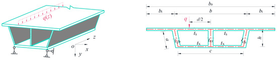
Figure 1.
Section dimensions and applied loads.
In the figure, represent the top slab width between the side webs, the flange width, and the total width of the top slab, the bottom slab width, section height, and inclined web length. represents the thickness of the top slab, side web, middle web, and bottom slab. d/2 represents the distance from the action point of the eccentric load q on the top slab to the middle web.
When calculating the transverse internal forces of a single-box double-cell concrete box girder using the Frame Method, the following basic assumptions should be made.
- The axial deformation of each plate component constituting the frame is negligible, meaning the perimeter of the box-shaped cross-section is considered incompressible, with a transverse strain of 0.
- When a box girder undergoes distortion-induced warping, the individual plates constituting the box section serve as the cross-sections of longitudinal plate girders, each satisfying the plane-section assumption.
- Neglecting the influence of the thickness of each plate component of the box girder on warping, i.e., the shear stress and warping normal stress are uniformly distributed along the wall thickness.
Following the principle of first applying and then releasing supports, virtual supports Ri (i = 1, 2) are introduced, as shown in Figure 2b. To release the virtual supports, equivalent counteracting forces qi (i = 1, 2) are subsequently applied, as illustrated in Figure 2c.
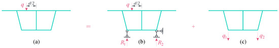
Figure 2.
(a) The box girder under eccentric loads; (b) The application of virtual supports; (c) The release of virtual supports.
The following results can be readily derived from the equilibrium relationship:
The transverse internal forces of the virtual support frame are determined using elementary mechanics analysis. The final results of these forces are illustrated in Figure 3.
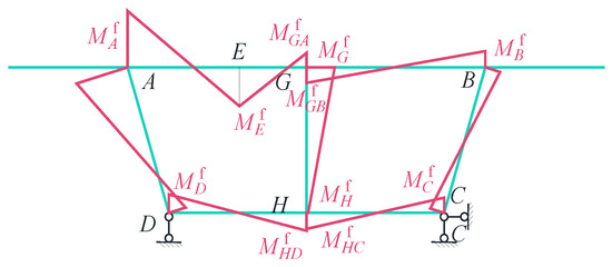
Figure 3.
Transverse internal forces of the virtual support frame.
In the figure, (i = A, B, C, D, E) denote the transverse internal forces of the virtual support frame at corner points A, B, C, D and E. Similarly, (i = G, H) denote the transverse internal forces at points G and H on the middle web. Lastly, (i = GA, GB, HD, HC) represent the transverse internal forces at point G on the top slab near the A and B ends, and at point H on the bottom slab near the D and C ends.
This paper investigates the transverse internal forces of releasing virtual supports. According to distortion theory, the load in Figure 4a can be decomposed, as illustrated in Figure 4.
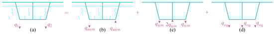
Figure 4.
(a) The release of virtual supports; (b) The torsion mode for releasing virtual supports; (c) The distortion mode for releasing virtual supports; (d) The bending mode for releasing virtual supports.
As shown in Figure 4, the release support loads qi (i = 1, 2) are decomposed into torsion mode (Figure 4b), distortion mode (Figure 4c), and bending mode (Figure 4d). The corresponding loads are , , and , respectively. Based on equivalence relationships, the following results can be derived:
Solving Equations (1) and (2) simultaneously yields:
As the bending mode does not generate transverse internal forces, only the transverse internal forces from the torsion and distortion modes are considered.
3. Torsion Mode
As illustrated in Figure 5a, the torsion mode load qasym can be decomposed into the rigid torsion load Vi and the anti-symmetric distortion load Ti .
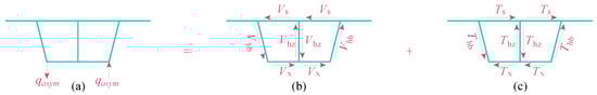
Figure 5.
(a) The torsion mode for releasing virtual supports; (b) The rigid torsion load of the torsion mode; (c) The anti-symmetric distortion load of the torsion mode.
In the figure, and represent the rigid torsion loads and anti-symmetric distortion loads corresponding to the top slab, bottom slab, side web, and middle web, respectively.
Under the action of the rigid torsion load Vi and the anti-symmetric distortion load Ti, the micro-frame undergoes rigid torsion and anti-symmetric distortion. The rigid torsion load Vi and anti-symmetric distortion load Ti vary along the beam segment. The rigid torsion load Vi and distortion load Ti on the front and rear faces of the micro-frame at any given cross-section differ, as illustrated in Figure 6.
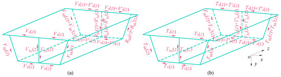
Figure 6.
(a) Shear force difference in the micro-frame of the rigid torsion load; (b) Shear force difference in the micro-frame of the anti-symmetric distortion load.
The load increments along the z-axis in the micro-frame are denoted as the torsional shear force difference and anti-symmetric distortion shear force difference , both of which can be considered external loads. The external loads acting on the unit-width frame structure are illustrated in Figure 7.
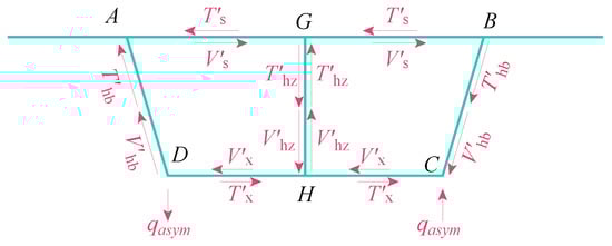
Figure 7.
Schematic diagram under external loads of unit-width frame.
In the analysis of external loads on the unit-width framework, the torsional shear difference and the anti-symmetric distortion shear difference on the web plate are equal in magnitude, opposite in direction, and act at the same location. When establishing the equilibrium, these forces cancel each other out and do not affect the final transverse internal forces.
For the torsional shear difference , applying the condition that the average torsional shear flow is equal, we obtain:
For the anti-symmetric distortion shear difference , in the overall analysis of the twin-cell micro-element framework, the anti-symmetric distortion shear difference at points G and H must satisfy the self-balancing condition, leading to the following results:
Since the torsional shear force difference does not generate transverse internal forces, only the anti-symmetric distortion shear force difference produces such forces. Based on the self-equilibrium of the anti-symmetric distortion shear force difference, the symmetric structure is simplified and calculated, and the transverse internal force diagram of the anti-symmetric distortion is obtained, as shown in Figure 8.
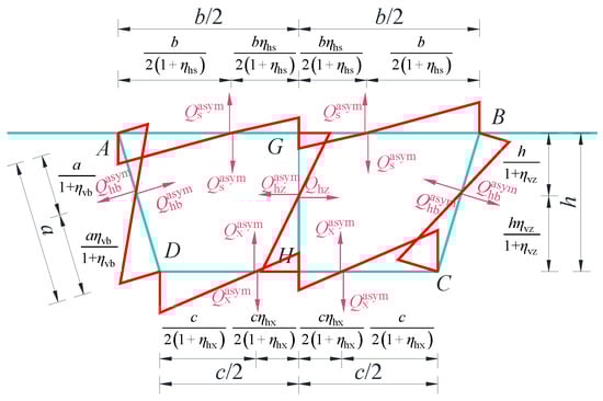
Figure 8.
Transverse internal forces resulting under the anti-symmetric distortion.
In the figure, represent the shear forces at the inflection points of zero bending moment on the top slab, bottom slab, side webs, and middle web, respectively. The inflection points of the top and bottom slabs divide each slab along its length into left and right segments, which are symmetrical with respect to the middle web, with ratios of and . The inflection points of the side and middle webs divide the web along its height into upper and lower segments, with ratios of and . Refer to the Appendix A for the specific expressions of the proportional coefficients.
From the moment equilibrium condition at the nodes, the following can be derived:
Under the action of the anti-symmetric distortion shear difference, the frame undergoes an anti-symmetric distortion effect, resulting in corresponding deformations. The connections between the displaced corner points are illustrated in Figure 9a, with the detailed displacement diagram shown in Figure 9b.
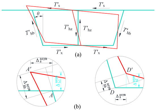
Figure 9.
(a) The connections between the displaced corner points; (b) Schematic diagram of corner A and D displacement.
From the proportional relationships, the following can be easily derived:
In the equation, , represent the vertical displacements at points A and D. represents the displacement along its own axis.
Based on the definition of the distortion angle, the expressions for the distortion angles and at points A and D can be obtained as follows:
In the equation, , , . is the distortion flexure coefficient (for the mid-span section of a simply supported beam under uniform load). Ec is the elastic modulus of the concrete material. , , represent the bending moments of inertia for the top plate, bottom plate, and side web in their own planes, respectively.
The inflection point of zero bending moment method is used to establish the frame calculation model, as shown in Figure 10, and the corresponding deformation diagram is presented.
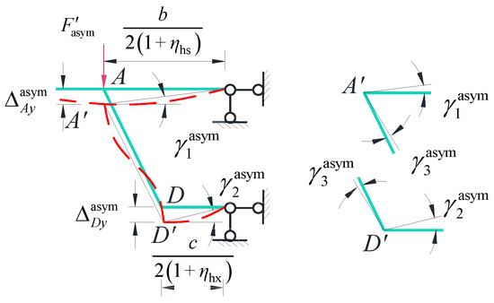
Figure 10.
Schematic diagram of anti-symmetric distortion frame deformation.
In the figure, the equivalent loads, denoted as , and represent the vertical displacements at corner points A and D under the equivalent loads. Under small deformation conditions, the rotation of the web members is neglected, .
Since the frame structure is derived from the box girder, the relative displacements of the frame should correspond to the relative displacements associated with the distortion angle. The distortion displacement coordination relations for points A and D are as follows:
By substituting the distortion displacement expressions and applying the force method principle to calculate the vertical displacements at the frame’s corner points, the simplified result is obtained:
In the equation, , represent the transverse moment of inertia per unit length of the top slab, bottom slab, side webs, and middle web of the frame, respectively. . represents the Poisson’s ratio of the material.
From the equilibrium of horizontal forces (Figure 11), vertical forces (Figure 12), and rotational equilibrium (Figure 13), the following results are derived:
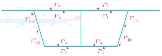
Figure 11.
Schematic of horizontal force equilibrium.
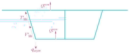
Figure 12.
Schematic of vertical force equilibrium on torsion mode.
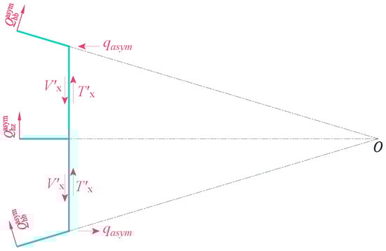
Figure 13.
Schematic of rotational equilibrium.
4. Distortion Mode
The analysis for the distortion mode is analogous to that of the torsional mode. As illustrated in Figure 14, the distortion mode can be decomposed into a symmetric distortion load .
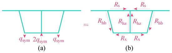
Figure 14.
(a) The distortion mode for releasing virtual supports; (b) The Load decomposition diagram of the distortion mode.
The external loads acting on the frame structure are illustrated in Figure 15.
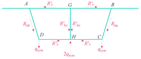
Figure 15.
Schematic of external loads acting on the unit-width frame.
In the figure, the symmetric distortion shear force differences correspond to the top slab, bottom slab, side webs, and central web, respectively.
Based on the self-equilibrium relationship of the symmetric distortion shear difference , the analysis of both the entire structure and the single-cell structure yields the following results:
Similarly, by utilizing the self-equilibrium of the anti-symmetric distortion shear force difference, the symmetric structure is simplified and calculated to obtain the transverse internal force diagram of the symmetric distortion, as shown in Figure 16.
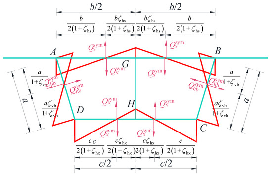
Figure 16.
Transverse internal forces in the symmetric distortion frame.
In the figure, represent the shear forces at the inflection points of zero bending moment on the top slab, bottom slab, side webs, and central web, respectively. The inflection points of the top and bottom slabs divide each slab along its length into left and right segments, which are symmetrical with respect to the middle web, with ratios of and . The inflection points of the side webs divide it along its height into upper and lower segments, with ratios of . Refer to the Appendix A for the specific expressions of the proportional coefficients.
From the moment equilibrium condition at the joints, the following results can be derived:
Under the action of the symmetric distortion shear force difference, the frame undergoes a symmetric distortion effect, resulting in corresponding deformations. The connections between the displaced corner points are illustrated in Figure 17.
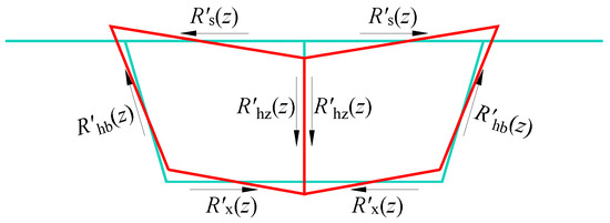
Figure 17.
Schematic of corner displacement.
Similarly, based on the distortion displacement compatibility relationship, it can be obtained:
In the equation, . The bending moments of inertia of the top plate, bottom plate, middle web in their own planes are , , , respectively. .
From the vertical force equilibrium, as shown in Figure 18, the following results can be obtained:

Figure 18.
Schematic of vertical force equilibrium on distortion mode.
At this stage, the transverse internal forces of the released virtual support is divided into torsional and distortion modes. The torsional mode requires solving simultaneous Equations (3)–(9) and (13)–(16), while the distortion mode involves Equations (3) and (17)–(23). By analyzing the relationship between shear force and bending moment at the inflection point, the transverse internal forces at point A, resulting from both modes, are determined.
5. Numerical Example Analysis
5.1. Numerical Example 1
To verify the applicability and reliability of the proposed method, the single-box twin-cell simply supported rectangular box girder from the literature [20] was analyzed using this method. The box girder has a length of 3.5 m. Its cross-sectional dimensions and the Eccentric load application position are shown in Figure 19, and the eccentric load q = 10 kN is illustrated. The elastic modulus of the box girder material is 29 GPa, with a Poisson’s ratio of 0.18. The finite element model was established using the shell181 element in ANSYS 12.1, comprising a total of 74,192 elements and 73,820 nodes.
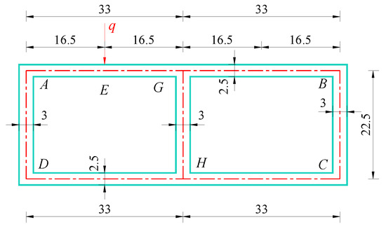
Figure 19.
Schematic diagram for the cross-section calculation of a single-box twin-cell rectangular box girder (cm).
Several key proportional coefficients used in the calculation are listed in Table 1.

Table 1.
Key proportional coefficient of the single-box twin-cell rectangular box girder.
Based on Equations (24) and (25) and the corner bending moment relationships provided in Appendix A, the component transverse internal forces and the final transverse internal forces at key points are calculated and summarized. The corresponding results obtained from the finite element method (FEM) are also presented in Table 2. Only consider the calculation points related to the bridge deck. In order to give a clearer representation of the actions on the section obtained both with the proposed method and with the FEM model, there is a comparison in Figure 20.
Table 2.
The transverse internal forces at key points on the mid-span cross-section of the single-box twin-cell rectangular box girder (Unit: kN·m /m).
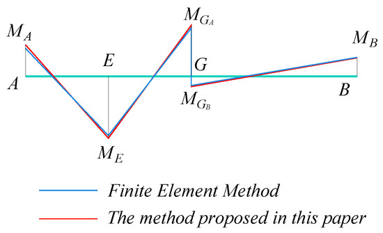
Figure 20.
The diagram of top slab transverse internal force for single-box twin-cell rectangular section box girder.
Based on the comparison of the data in Table 2, the transverse internal force calculation method proposed in this study demonstrates a small relative error compared to the finite element analysis (FEA) results at all calculation points. This result effectively validates the high accuracy of the proposed method. Additionally, as can be seen from Figure 20, the overall trend of the calculation results at these positions maintains a high degree of consistency with the finite element analysis method, further confirming the validity and consistency of the proposed calculation approach.
5.2. Numerical Example 2
The cross-sectional form is illustrated in Figure 21. A simply supported concrete box girder with a span of 30 m is selected as the calculation model. An eccentric load of q = 10 kN is applied at the position shown in Figure 21. The finite element model is built using Shell181 elements in ANSYS, consisting of 869,691 elements and 868,823 nodes.
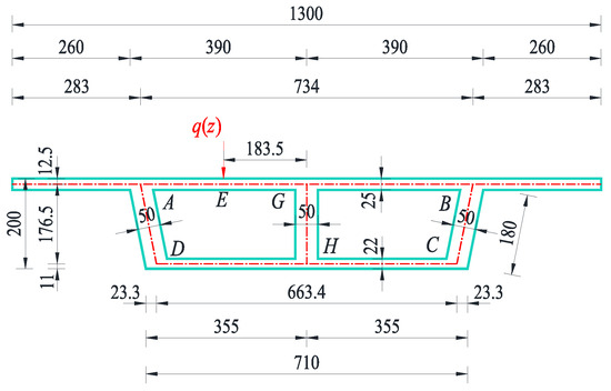
Figure 21.
Schematic diagram for the cross-section calculation of a single-box twin-cell inclined web box girder (cm).
Several key proportional coefficients used in the calculation are listed in Table 3.
Table 3.
Key proportional coefficients of the single-box twin-cell inclined web box girder.
Table 4 presents the component transverse internal forces and the final transverse internal forces at key points calculated by the method proposed in this paper. The corresponding results obtained from the finite element method (FEM) are also presented. Figure 22 gives a clearer representation of the actions on the section obtained both with the proposed method and with the FEM mode. The transverse internal forces of the bottom slab were amplified by 5 times for comparison.
Table 4.
The transverse internal forces at key points on the mid-span cross-section of the single-box twin-cell inclined web box girder (Unit: kN·m/m).
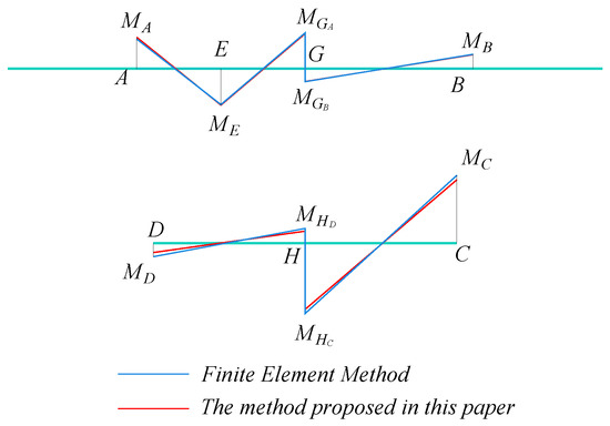
Figure 22.
The diagram of top and bottom slab transverse internal force for single-box twin-cell inclined web box girder.
Based on the comparison of the data in Table 4, the transverse internal force calculation method proposed in this study demonstrates a relative error of less than 7% compared to the finite element analysis (FEA) results at all calculation points, except for points D and HD. This result effectively validates the high accuracy of the proposed method. It is worth noting that, although points D and HD exhibit relatively higher errors due to the smaller magnitude of their final transverse internal forces, the overall trend of the calculated results at these points still aligns closely with those obtained using the FEA method, as can be seen from Figure 22. This further confirms the effectiveness and consistency of the proposed calculation method.
To further analyze the relative magnitudes of the frame transverse internal forces, anti-symmetric distortion transverse internal forces, and symmetric distortion transverse internal forces, the symbol is defined to represent the proportion, and the proportions at each key point are illustrated in Figure 23.
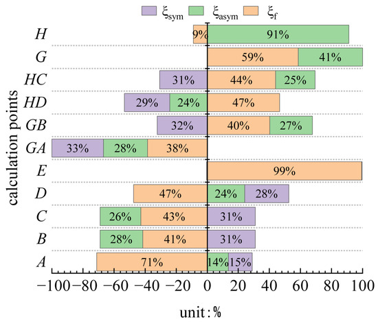
Figure 23.
Proportion of component transverse internal forces at each calculation point.
As shown in Figure 23, the calculation points located at the intersections of the top plate, bottom plate, and webs (i.e., A, B, GA, GB and C, D, HC, HD) exhibit slight differences in the tensile and compressive behaviors of transverse internal forces caused by symmetrical and anti-symmetrical distortions between direct load-bearing chamber points (i.e., A, GA, HD, D) and indirect load-bearing chamber points (i.e., GB, B, C, HC). However, their overall proportions remain very close. This observation suggests that the transverse internal forces induced by symmetrical distortion effects play a significant role and cannot be overlooked. At the load application points, the contributions of transverse internal forces from symmetrical and anti-symmetrical distortions are negligible. This occurs because the load is applied at the center of the half top slab, where the sectional ratio coefficients are nearly equal to 1. At the middle web calculation points (i.e., G and H), the symmetrical distortion effect has no significant influence on the transverse internal forces.
6. Parameter Analysis
To clearly illustrate the effect of the web inclination angle θ and the middle web thickness thz on the transverse internal forces at the top slab and middle web calculation points, the combined transverse internal force, resulting from torsional and distortion modes, is defined as the distortion-effect transverse internal force ().
The web inclination angle θ is adjusted from 0 to 45 degrees by varying the edge web length b and the bottom plate length c, while keeping the top slab parameters and the applied load constant. The variation of the final transverse internal forces at the top slab and middle web calculation points with respect to θ is shown in Figure 24.
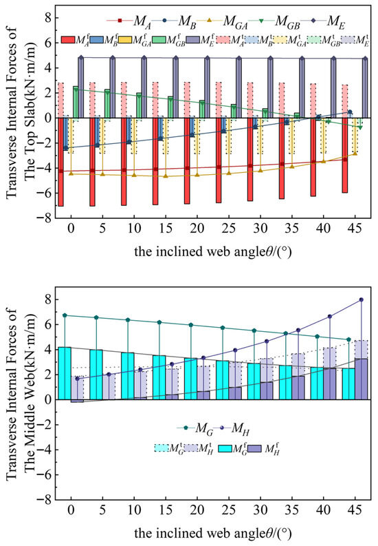
Figure 24.
The variation curve of the transverse internal force with respect to the web inclination angle θ.
As the web inclination angle θ increases, Figure 21 shows that the transverse internal forces at the top slab calculation points (A, B, GA, GB, E) reach their extreme values at θ = 0. The variation curves of transverse internal forces at the load directly affected points (A, GA, E) are smoother compared to the indirectly affected points (B, GB). The transverse internal forces at the middle web are significantly influenced by the web inclination angle θ. Specifically, as θ increases from 0° to 45°, the transverse internal force at point G decreases by 30%, while at point H, it increases by 3.8 times.
With the parameters of the top slab, bottom slab, and side webs kept constant, the middle web thickness is adjusted to modify the web thickness ratio . The scenario in which the mid-web thickness is zero (resulting in the degradation of the twin-cell into a single chamber, preventing symmetric distortion effects) is temporarily excluded. The variation curves of the final transverse internal forces at the calculation points on the top plate and the middle web with respect to the web thickness ratio are presented in Figure 25.
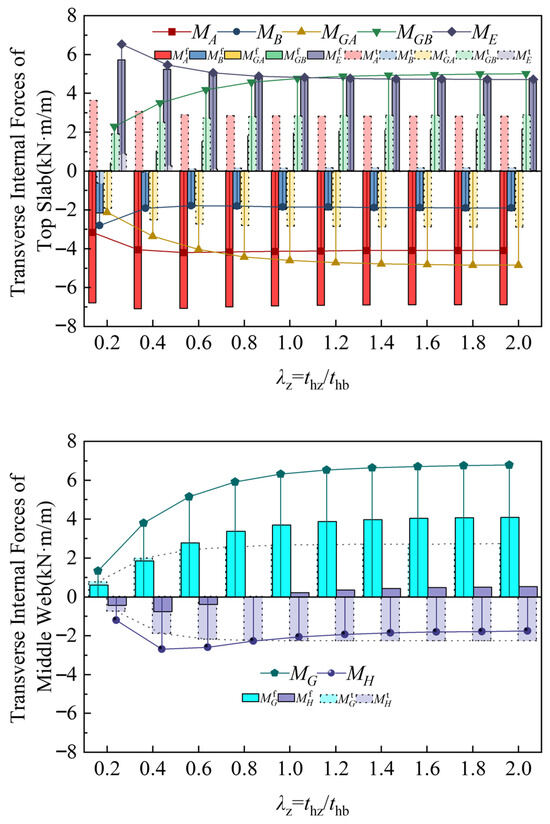
Figure 25.
The variation curve of the transverse internal force with respect to the web thickness ratio.
When the mid-web and side web have equal thickness (λz = 1), the transverse internal force at each point stabilizes. Further increases in mid-web thickness result in insignificant changes in the transverse internal force at each point.
7. Conclusions
- This study employs frame analysis to systematically explore the structural behavior of twin-cell inclined web box girders. A generalized formula is derived to compute the transverse internal forces resulting from both symmetric and anti-symmetric distortion modes. Validation through case studies demonstrates a strong correlation between the proposed formula and finite element analysis (FEA) results, with relative errors consistently maintained below 7%.
- During the release of virtual support loads, three primary deformation modes are identified: torsion, distortion, and bending. Among these, the transverse internal forces in the box girder are predominantly influenced by torsion and distortion modes, with the distortion mode not directly affecting transverse internal forces in the mid-web. In the case studies presented in this paper, while the distortion mode induces tension-compression effects on the top and bottom slabs distinct from those of the torsion mode, the transverse force magnitudes in both modes remain comparable. As the load application point approaches the mid-web, the impact of the distortion mode becomes increasingly significant.
- This study systematically investigates the distribution patterns of transverse internal force inflection points in single-box, twin-cell box girders with inclined webs under torsion mode and distortion mode. The findings indicate that the widely accepted assumption of placing the transverse bending moment inflection point at the center of the single-side top plate is inaccurate. Instead, the position of the inflection point is shown to be significantly influenced by the relative stiffness of individual plate components, necessitating a more holistic consideration of stiffness distribution in engineering design.
- For engineering design purposes, when calculating the transverse internal force of single-box twin-cell box girder with inclined web, it is possible to estimate by using the rectangular section with the same top slab, and the transverse internal force has a considerable safety reserve. However, the influence of the thickness of the middle web plate on transverse internal forces requires special attention. When the middle web thickness is smaller than that of the side web, significant variations in transverse internal forces occur at the calculation points. As the thicknesses become equal, the fluctuations in transverse internal forces stabilize. Further increasing the central web thickness causes no notable changes in the transverse internal forces at each point. For detailed design, the calculation method in this paper can be required.
This paper focuses solely on studying the transverse internal forces of the single-box twin-cell concrete simply supported box girder bridge deck with inclined webs, where the cross-section of the girder exhibits symmetry. Therefore, further research is still required for the transverse internal forces of other bridge structures or single-box twin-cell concrete simply supported box girders with asymmetric cross-sections.
Author Contributions
Conceptualization, Y.Z. (Yuanhai Zhang); Methodology, J.Y., F.Z. and Y.Z. (Yuanhai Zhang); Validation, J.Y.; Formal analysis, J.Y., F.Z., Y.Z. (Yuyuan Zhang) and Y.W.; Data curation, J.Y. and Y.W.; Writing—original draft, J.Y.; Writing—review & editing, Y.Z. (Yuanhai Zhang) and Y.Z. (Yuyuan Zhang); Supervision, J.Y., Y.Z. (Yuanhai Zhang) and Y.Z. (Yuyuan Zhang); Project administration, Y.Z. (Yuanhai Zhang); Funding acquisition, Y.Z. (Yuanhai Zhang). All authors have read and agreed to the published version of the manuscript.
Funding
This work was completed under the support of the National Natural Science Foundation of China (Grant No. 52368020) and Gansu Province’s Young Doctoral Support Program for Colleges and Universities(Grant No. 2024QB-047).
Data Availability Statement
The data presented in this study are available on request from the corresponding author.
Conflicts of Interest
The authors declare no conflicts of interest.
Appendix A
If the general section is reduced to a doubly symmetric rectangular section, i.e., , , , , the above proportional coefficients can be simplified to:
Appendix B
Table A1.
The nomenclature table of parameters.
Table A1.
The nomenclature table of parameters.
| Load Mode | Parameter | Meaning | Unit |
|---|---|---|---|
| Torsion | torsional shear force difference | kN·m/m | |
| anti-symmetric distortion shear difference | kN·m/m | ||
| shear force at the inflection points of bending moment on the simplified structure | kN·m/m | ||
| shear force at the inflection points of bending moment on the unit-length frame | kN·m/m | ||
| The proportion coefficient of the plate lengths on both sides of the inflection point | / | ||
| The coordination proportional coefficient of distortion displacement | / | ||
| Distortion | symmetric distortion shear difference | kN·m/m | |
| shear force at the inflection points of bending moment on the simplified structure | kN·m/m | ||
| shear force at the inflection points of bending moment on the unit-length frame | kN·m/m | ||
| The proportion coefficient of the plate lengths on both sides of the inflection point | / | ||
| The coordination proportional coefficient of distortion displacement | / |
The above correlation coefficients are proportional coefficients considering the influence of transverse bending stiffness of each plate component, which have no physical meaning and are dimensionless proportional coefficients.
References
- Li, H. Review on Special Issues in Prestressed Concrete Box Girders with Corrugated Steel Webs. J. Basic Sci. Eng. 2018, 26, 440–454. (In Chinese) [Google Scholar]
- Maguire, M.; Moen, C.D.; Roberts-Wollmann, C.; Cousins, T. Field Verification of Simplified Analysis Procedures for Segmental Concrete Bridges. J. Struct. Eng. 2014, 141, D4014007. [Google Scholar] [CrossRef]
- Kurian, B.; Menon, D. Correction of Errors in Simplified Transverse Bending Analysis of Concrete Box-Girder Bridges. J. Bridge Eng. 2005, 10, 650–657. [Google Scholar] [CrossRef]
- Guo, J.; Zheng, Z. Analysis of Transverse Internal Forces in Box Girder Bridges with Cantilevers. China Civ. Eng. J. 1986, 3, 59–72. (In Chinese) [Google Scholar]
- He, J.; Zhang, Y.; Huang, H. Research on Modification Factor of Transverse Internal Force of Thin-walled Box Girder considering Distortion Effect. J. China Railw. Soc. 2022, 44, 140–146. (In Chinese) [Google Scholar]
- Wang, Z. Investigation of the transverse internal force of a box girder using the energy variational principle. Gradevinar 2024, 76, 235–245. [Google Scholar]
- Zhou, M.; Zhang, J.; Yang, D.; Hassanein, M.F.; An, L. Transverse Analysis of a Prestressed Concrete Wide Box Girder with Stiffened Ribs. J. Bridge Eng. 2017, 22, 4017046. [Google Scholar] [CrossRef]
- Shushkewich, W. Transverse Analysis of Strutted Box Girder Bridges. J. Bridge Eng. 2006, 11, 33–47. [Google Scholar]
- Xu, F.; Cheng, Y.; Wang, K.; Zhou, M. Transverse Analysis of Box Girders with Corrugated Steel Webs. Buildings 2024, 14, 574. [Google Scholar] [CrossRef]
- Choi, Y.; Oh, B. Transverse Modeling of Concrete Box-Girder Bridges for Prediction of Deck Slab Ultimate Load Capacity. J. Bridge Eng. 2013, 18, 1373–1382. [Google Scholar] [CrossRef]
- Park, N.; Choi, S.; Kang, Y. Exact distortional behavior and practical distortional analysis of multi cell box girders using an expanded method. Comput. Struct. 2005, 83, 1607–1626. [Google Scholar]
- Razaqpur, A.; Li, H. Thin-Walled Multi cell Box-Girder Finite Element. J. Struct. Eng. 1991, 117, 2953–2971. [Google Scholar] [CrossRef]
- Wei, Y.H.; Zhang, Y.H. Analysis on distortion effect of twin-cell box girders with inclined side webs based on finite beam-segment element. Thin-Walled Struct. 2025, 212, 113137. [Google Scholar] [CrossRef]
- Li, X.; Li, L.; Zhou, M.; Wan, S.; Chen, J.; Kang, A. Refined beam finite element model for thin-walled multi-cell box girders considering distortion and secondary distortional moment deformation effect. Eng. Struct. 2024, 298, 117042. [Google Scholar] [CrossRef]
- Zhang, Y.; Wang, C.; Zhang, X.; Li, Y. Exact distortional behavior of single-box multi cell curved composite box girders with corrugated steel webs in the elastic stage. Eng. Struct. 2023, 297, 116961. [Google Scholar] [CrossRef]
- Chithra, J.; Praveen, N.; Sajith, A. Transverse Bending Analysis of Twin-Cell Concrete Box Girder Bridges Using Simplified Frame Analysis. Pract. Period. Struct. Des. Constr. 2023, 28, 1–9. [Google Scholar]
- Chithra, J.; Nagarajan, P.; Sajith, A. Simplified method for the transverse bending analysis of twin celled concrete box girder bridges. IOP Conf. Ser. Mater. Sci. Eng. 2018, 330, 012118. [Google Scholar] [CrossRef]
- Zhao, P.; Ye, J. Transverse force study of single box multi-chamber with corrugated steel webs. J. Harbin Eng. Univ. 2018, 39, 1109–1115. (In Chinese) [Google Scholar]
- Wang, Z.; Zhang, Y. Research on Transverse Internal Force of Single Box Double Cell Composite Box Girder with Corrugated Steel Webs. J. China Railw. Soc. 2019, 41, 106–112. (In Chinese) [Google Scholar]
- Zhang, S.H. The Finite Element Analysis of Thin-Walled Box Spine-Beam Bridges; University of London: London, UK, 1982. [Google Scholar]
Disclaimer/Publisher’s Note: The statements, opinions and data contained in all publications are solely those of the individual author(s) and contributor(s) and not of MDPI and/or the editor(s). MDPI and/or the editor(s) disclaim responsibility for any injury to people or property resulting from any ideas, methods, instructions or products referred to in the content. |
© 2025 by the authors. Licensee MDPI, Basel, Switzerland. This article is an open access article distributed under the terms and conditions of the Creative Commons Attribution (CC BY) license (https://creativecommons.org/licenses/by/4.0/).