Abstract
To meet the growing requirements of agricultural mechanization, a newly designed 9.5 m span frame has been introduced to replace the traditional 8.0 m span frame, which is constrained by limited internal space. However, as the structural dimensions increase, the failure mechanisms of arch frames under wind loads remain insufficiently understood. In particular, the influences of crop loads, initial geometric imperfections, pipe cross-sectional properties, and cable reinforcement on these failure mechanisms have not yet been systematically investigated. This study aims to reveal the mechanical mechanisms governing the wind-bearing capacity of standard 8.0 m span and newly designed 9.5 m span frames through comparative analysis, and to further investigate how crop loads, initial geometric imperfections, pipe cross-sectional properties, and cable reinforcement modify these mechanisms. The load combinations considered included the following: (1) permanent load + wind load and (2) permanent load + crop load + wind load. The crop load was applied to the frames via a 5-point hanging system. Simulation results indicate that the 9.5 m span frame exhibits a lower allowable wind speed (va) than the 8.0 m span frame due to strength failure. Further analysis reveals that the failure is governed by decreased stiffness resulting from the dimensional expansion. Notably, crop loads and initial geometric imperfections were found to amplify second-order bending moments, thereby further decreasing va. Moreover, a positive linear correlation is observed between the section modulus of pipes and va. However, replacing the circular pipe with rectangular, oval, or elliptical pipes of a similar cross-sectional area does not increase the va of the 9.5 m span frame. Conversely, reinforcing the 9.5 m span frame with cables provides strong lateral constraints and effectively suppresses the amplification of bending moments arising from crop loads and initial geometric imperfections. Thus, limiting lateral displacement through reinforcement measures can markedly increase the wind-bearing capacity of frames. The reinforced 9.5 m span frame proves to be a viable replacement for the 8.0 m span frame, meeting the modern demands of facility agriculture in Southern China.
1. Introduction
Plastic greenhouses are simple horticultural facilities constructed with steel pipe frames and covered by transparent plastic film. They have been widely used worldwide due to their low construction cost, increased yield, and protection from harsh conditions [1]. However, these facilities typically use thin-walled steel pipes to construct their frames, which often results in low levels of safety [2]. Consequently, they are highly susceptible to damage from strong winds, leading to significant economic losses [3,4,5]. Therefore, the structural integrity of plastic greenhouses under strong winds has received increasing attention in the horticultural industry [6].
The 8.0 m span plastic greenhouse is predominantly used for crop cultivation in this region in southern China (Figure 1a). However, its restricted internal space limits the application of agricultural machinery. To overcome this limitation, a 9.5 m span plastic greenhouse with the same steel usage per unit floor area has been introduced (Figure 1b). Nevertheless, it is noted that larger plastic greenhouses are more vulnerable to damage from wind and snow loads compared to their smaller counterparts [7]. Thus, it is critical to thoroughly investigate the wind-induced mechanical behavior of the two types of arches and identify the key factors affecting their wind-bearing performance, so as to provide a theoretical basis and engineering reference for the demonstration and wider application of this type of plastic greenhouse.

Figure 1.
Photographs of plastic greenhouse frames: (a) 8.0 m span frame; (b) 9.5 m span frame.
Many studies have investigated the failure mechanisms of greenhouse arch frames under wind loads. Toyoda et al. [8] reported that the deformation of a two-span Gabic even greenhouse increased sharply once the wind speed exceeded 40 m·s−1, ultimately leading to structural collapse at a wind speed of 50 m·s−1, as demonstrated by the load–displacement curve. Takahashi and Uematsu [9] documented the deformation and collapse process of a 5.4 m span plastic greenhouse under winds and determined the wind speeds at which frame deformation and stress reached their allowable thresholds. Lei et al. [10] identified the maximum wind speed that a plastic greenhouse could withstand based on the stress levels within the frame. Ding et al. [11] reported similar findings by examining the load–displacement curves of a plastic greenhouse frame. Furthermore, Ren et al. [12] conducted tests on the structural integrity of a 20.0 m span plastic greenhouse by comparing the critical buckling loads with the design loads. Sim and Jung [13] assessed the failure probability of a carbon-fiber-reinforced single-span greenhouse under wind loads and found that excessive lateral displacement was the primary cause of failure. Lee and Ryu [14] performed numerical analyses considering the semi-rigid behavior of cross-connected members to investigate the collapse mechanism of pipe-frame greenhouses. Jeon et al. [15] showed that increasing greenhouse height leads to a nonlinear increase in structural vulnerability.
A substantial body of research has examined the effects of dynamic wind loads on greenhouse frames. Xie et al. [16] reported that for a plastic greenhouse with flattened-oval tubes, the maximum displacement and stress induced by fully dynamic wind loads were 2.57 and 1.53 times those under mean wind conditions, respectively. Similarly, Jiang et al. [17], Wang et al. [8], and Li et al. [18] found that dynamic wind loads produced larger displacements and stresses in plastic greenhouses compared with mean wind loads.
Given that the selection of wind pressure coefficients directly affects the reliability of simulation results, existing studies have sought to improve their accuracy through multiple approaches. These efforts include not only quantifying the differences among various national design codes and evaluating the resulting deviations [4], but also employing computational fluid dynamics simulations to capture and determine the detailed distribution of wind pressure coefficients over specific roof regions [19,20].
In addition to frame structure, the wind-bearing capacity of plastic greenhouse frames can also be influenced by factors such as self-weight, frame supports, and combinations of loads. Hur et al. [21] found that the self-weight of a Venlo-type greenhouse can help mitigate the effects of wind loads on the frame when the wind speed is under 20 m·s−1, but this mitigation becomes negligible once the wind velocity exceeds 20 m·s−1. Moreover, Ha et al. [22] concluded that the structural behavior of a multi-span plastic greenhouse frame under wind loads could be affected by the methods of connection and support, while Takahashi and Uematsu et al. [9] concluded that the component connection method exerted negligible effects on frame deformations for a 5.4 m span arched plastic greenhouse under wind. Furthermore, it has been reported that the cross-section of pipes used for constructing frames could affect the snow-bearing capacity of a Chinese solar greenhouse frame [23].
Due to low construction budget, plastic greenhouses are typically designed as temporary steel structures, making them inadequate for resisting strong wind and heavy snow loads [24]. One common method used for improving the wind-bearing capacity of greenhouse frames is increasing the sectional dimension of frame pipes. However, this approach would increase the construction cost and make the plastic greenhouse economically infeasible [25]. In accordance with the findings of Maraveas and Tsavdaridis [26], structural reinforcement is a viable solution to enhance the wind-bearing capacities of plastic greenhouse frames. Moreover, several reinforcing techniques for vaulted and Venlo-type multi-span greenhouses have been proposed along with an assessment methodology. Takahashi and Uematsu [27] examined seven reinforcing methods for a pipe greenhouse and recommended adopting methods that effectively inhibit the deformation of windward columns. Jeon et al. [15] showed that local reinforcement measures can reduce the high failure probability caused by increased geometric dimensions from 79% to a safe level of 10%. Dong et al. [28] found that adopting a double-layer tie-rod system effectively redistributes internal forces and significantly mitigates the second order (P-Δ) effect.
Despite existing studies, a systematic understanding of the structural stability differences between standard 8.0 m and large-span 9.5 m frames under wind loads in Southern China is still lacking. Specifically, the quantitative influence of this structural dimension increment on the frame’s initial stiffness, wind-induced response characteristics, and specific failure modes remains unclear. Moreover, Solanaceous crops are typically suspended directly from the frames, subjecting the frames to simultaneous wind and crop loads. Additionally, initial geometric imperfections arising from manufacturing and construction errors are inevitable. However, it remains to be elucidated whether these factors could amplify second-order effects, accelerate stiffness degradation, and thereby compromise the frame’s wind-bearing capacity mechanism. Finally, in addition to traditional circular steel pipes, advancements in construction technology have introduced alternative cross-sections such as square, rectangular, flat oval, and oblate elliptical shapes, as well as temporary reinforcement measures. Nevertheless, the specific mechanisms by which these factors influence the structural stability and failure behavior of the frames remain to be fully elucidated.
With the advancement of computer and numerical technologies, finite element analysis methods have become increasingly common in recent research. These methods have proven to be effective tools for investigating and optimizing greenhouse frames, particularly given that pipe greenhouses often collapse or sustain damage due to strong winds each year in Southern China. The purpose of this study is to (1) comparatively analyze the wind-induced response characteristics and reveal the mechanism of how the structural dimension increment degrades the frame’s wind-bearing capacity; (2) clarify the influences of crop loads and pipe cross-sections on this failure process; and (3) validate the effectiveness of cross-section types and cable reinforcement in suppressing lateral deformation and enhancing wind-bearing capacity.
2. Materials and Methods
2.1. Plastic Greenhouse Structure
Figure 2a,b illustrate the cross-sectional diagrams of the 8.0 m span and the 9.5 m span plastic greenhouse frames. The 8.0 m span frame has an eave height of 1.5 m and a ridge height of 3.5 m, while the 9.5 m span frame has an eave height of 2.15 m and a ridge height of 4.5 m. The gap between adjacent frames of both plastic greenhouses is 0.65 m. Additionally, two reinforcement cables were anchored atop the 9.5 m span frame side-columns to enhance its wind-bearing capacity (Figure 2c). This frame, equipped with the reinforcement cables, is referred to as the reinforced frame in the subsequent sections.
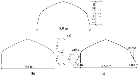
Figure 2.
Cross-sectional diagrams of plastic greenhouse frames: (a) 8.0 m span frame; (b) 9.5 m span frame; (c) reinforced frame.
2.2. Pipe Cross-Section
In southern China, the frame of 8.0 m span plastic greenhouse is typically constructed using circular pipes, as shown in Figure 3a. These pipes were used for both the 8.0 m span and 9.5 m span frames in this study to assess their structural stability under wind load. Furthermore, rectangular, oval, and elliptical cross-sections, with areas matching those of DN20 pipes, were employed to examine the effect of cross-section on the va of the frames (Figure 3 and Table 1). Moreover, the major axis of the oval and elliptical pipes was aligned parallel to the plane of the frame to optimize the bending performance. Additionally, the reinforcement cable for the 9.5 m span frame has a solid circular cross-section with a 2.0 mm diameter.

Figure 3.
Cross-section of pipes: (a) circular; (b) rectangular; (c) oval; (d) elliptical.

Table 1.
Parameters of cross-sectional characteristics for pipes.
2.3. Loads
External loads acting on a greenhouse frame can be categorized as permanent loads (G), crop loads (C), and wind loads (wk). Since the pipe greenhouses considered in this study are located in southern China, where the climate is warm, and greenhouse damage mainly occurs under strong wind conditions, snow load effects were not considered in this study.
2.3.1. Permanent Loads
The permanent load refers to the self-weights of the plastic film, the frame, and the permanently fixed equipment. The contribution of permanently fixed equipment was ignored in this study since there is typically no equipment fixed to the frames. Therefore, only the self-weights of the plastic film and the frames were considered as the permanent load. The covering film is typically 0.15 mm PEP plastic film. The permanent load due to the film was determined to be 1.5 N·m−2 according to the provisions of the Chinese standard GB/T 51183-2016 [29].
2.3.2. Crop Loads
Solanaceous crops are among the most important crops cultivated in greenhouses. Typically, these crops are suspended using hanging wires fixed to the arches, and the impact of crop loads on the frame’s wind-bearing capability must be considered. According to the Chinese standard GB/T 51183-2016 [29], the crop hanging system is designated as the 5-point hanging system (Figure 4). The crop loads are applied to the frames as concentrated forces through these hanging wires. The forces acting on the roof of the frames (FR) can be calculated using Equation (1). The forces acting on the eaves are divided into horizontal (FH) and vertical (FV) components, and these can be calculated using Equations (2) and (3).
where D is the span of plastic greenhouses, m; d is the distance between adjacent frames, m; n is the number of points where the hanging wire is fixed on the roof; C is crop loads, 150 N·m−2; l is the distance between the adjacent support points of the horizontal wire, m; f is the sag of horizontal wires, which can be deemed l/30 [29].
FR = C × d × D/2/n
FH = C × d × l2/(8f)
FV = C × d × l/2
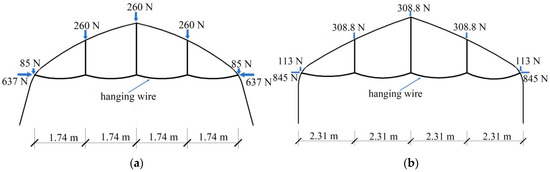
Figure 4.
Five-point hanging system and concentrated forces generated by crop loads: (a) 8.0 m span plastic greenhouse; (b) 9.5 m span plastic greenhouse.
2.3.3. Wind Load
The Chinese standard GB/T 51183-2016 [29] requires the calculation of wind pressures that act on the plastic greenhouses with wind speeds measured at 3 s intervals to consider the effects of wind vibrations on plastic greenhouse frames [30]. The wind loads are calculated using the following equations.
where wk is the standard value of the wind load, N·m−2; μs and μz are the wind pressure coefficient and the wind pressure height variation coefficient, respectively; w0 is the basic wind pressure, N·m−2; v is the instantaneous wind speed measured every 3 s, m·s−1.
wk = μs × μz × w0
w0 = v2/1600
Under the transverse wind direction, the values of μs on the different zones of the 8.0 m span and 9.5 m span plastic greenhouses are determined according to the provisions of the Chinese standard GB/T 51183-2016 [29] and are shown in Figure 5. The μz of the 8.0 m span and 9.5 m span frames are calculated as 0.68 and 0.71, respectively, according to the provisions of the Chinese standard GB/T 51183-2016 [29].

Figure 5.
External wind pressure coefficient on the plastic greenhouses: (a) 8.0 m span plastic greenhouse; (b) 9.5 m span plastic greenhouse.
2.4. Load Combination
According to the Chinese standard GB/T 51183-2016 [29], the structural importance factor can be taken as 0.9. Then, two load combinations were analyzed, taking the wind loads as the dominant: (1) G + wk and (2) G + wk + C. The partial factors and combination value coefficients for each load are also determined according to the Chinese standard GB/T 51183-2016 [29] and are presented in Table 2.
Table 2.
Values of partial factors and combination coefficients for various load combinations.
2.5. Finite Element Model
It is assumed that the load distribution is consistent in the length direction but varies in the span direction. The loads were transferred from the film to the structural frame as described by Ren et al. [12]. Then, the frames in the center bay of the 8.0 m span and 9.5 m span plastic greenhouses were modeled using ANSYS Workbench 2022 R2 software. The frames and the reinforcement cables are represented using beam 188 elements and cable 580 elements, respectively. Moreover, all pipes and the cable are constructed from Q235 steel, with a yield strength of 235 MPa, a Young’s modulus of 206 GPa, a Poisson’s ratio of 0.3, and a density of 7850 kg·m−3. The Bilinear Kinematic Hardening (BKIN) model was used to describe the nonlinear characteristics of steel materials.
Typically, the frames of plastic greenhouses are constructed using two frame pipes connected at the ridge, with their bottoms embedded in the ground for anchorage. According to the Japanese Greenhouse Structure Design Standard [30], such embedment can be idealized as a fixed support, provided the depth exceeds 400 mm. The connections between the two frame pipes were modeled as rigid connections following the studies of Toyoda et al. [8], Ding et al. [11], Ren et al. [12], and Wang et al. [25]. Additionally, the connections of the reinforcement cables at the tops of the side columns, as well as their anchoring to the ground, were modeled as hinge connections, since the reinforcement cables cannot resist bending moments under these conditions.
A static structural analysis was performed with the large deflection option activated (Figure 6). The loading process was applied in two sequential steps to replicate the actual loading history. In Step 1, the self-weight and crop loads were applied to establish the initial stress state. In Step 2, the wind loads were incrementally imposed. The load–displacement path was traced using the method proposed by Zhou and Ju [31]. Moreover, the initial geometric imperfections were generated by horizontally displacing the top of the side columns by 95 mm, which accounted for 1% of the span, in the wind direction (Figure 7). This method follows the methodology proposed by Roux et al. [32] and the related guidelines specified in the Chinese standard GB 50017-2017 [33].
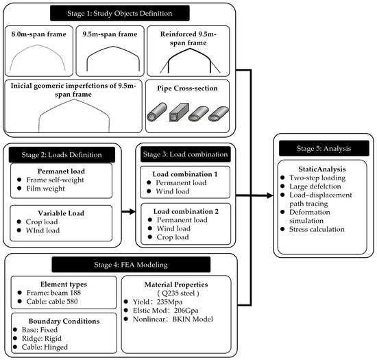
Figure 6.
Flowchart of the research methodology and finite element analysis procedure.
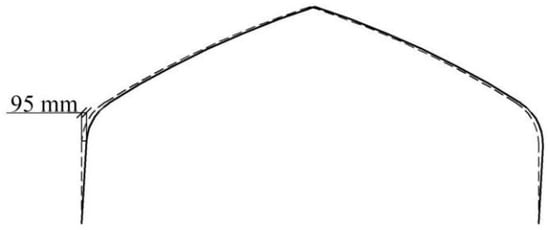
Figure 7.
Geometric imperfection for pipe frame. The dashed line indicates the ideal frame.
2.6. Stress Calculation and Analysis
The bending, shear, and axial stresses on the frames were calculated as follows:
where δb, τ, and δa are the bending, shear, and axial stresses, MPa; M is the bending moment, N∙m; W is the section modulus, mm3; Fs and Fa are the shear and axial forces, N; A is the cross-sectional area of pipes, mm2.
δb = M × 103/W
τ = Fs/(A × 10−6)
δa = Fa/(A × 10−6)
In the Chinese code GB/T 51183-2016 [29], the allowable stress design of steel pipes is set to 205 MPa. This allowable stress was subsequently used in the strength analysis of the frames.
3. Results
3.1. Validation of the Model
To verify the accuracy of the finite element model and solution parameters adopted in this study, a validation simulation was conducted based on the structural configuration and loading conditions reported by Kim et al. [4]. As shown in Table 3, the largest discrepancy was found in Case 5, where the maximum bending moment and stress were underestimated by 4.6% and 5.0%, respectively. Thus, the model is considered sufficiently reliable for the parametric study, given that these errors remain below 5%. In contrast, the proposed method overestimated the maximum axial force by approximately 38.0%. However, the mechanical behavior of the frame was dominated by bending moments as demonstrated by the subsequent results. The axial stress constituted a very small fraction of the total stress compared to the bending stress. Consequently, even with this overestimation, the fundamental internal force characteristics remained unchanged. Therefore, the proposed finite element model is considered sufficiently accurate and reliable for the subsequent parametric study.
Table 3.
Comparison between the simulation results of this study and the literature data (Kim et al. [4]).
3.2. Wind-Bearing Capacity of Frames Under Load Combination 1
In this study, displacements in the windward direction were considered positive. Figure 8 illustrates the ‘wind speed–displacement’ curve for the windward eave of the 8.0 m and 9.5 m span frames under load combination 1. Initially, the windward eave exhibited negative displacements due to the permanent loads. Then, the displacements increased with the wind speed following a cubic function form. Meanwhile, the 8.0 m span frame showed a much steeper curve in the initial loading stage, whereas the 9.5 m span frame exhibited a noticeably flatter one. The results imply that the expansion of frame span from 8.0 m to 9.5 m led to a reduction in the frame’s initial lateral stiffness.
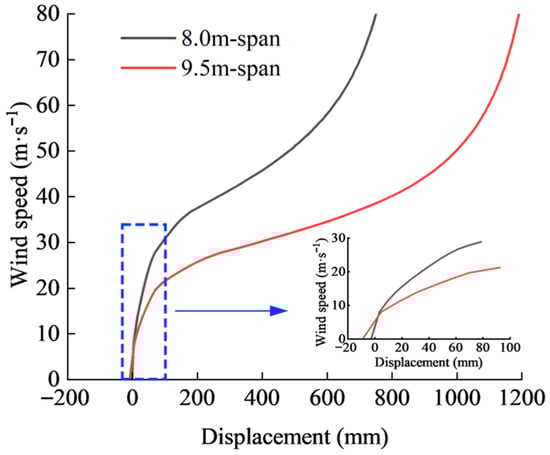
Figure 8.
‘Wind speed–displacement’ for windward eave of frames under load combination 1.
Given that the large deformations of the frames could alter μs, the accuracy of the simulation may be affected. Therefore, only data from when the horizontal displacements of the windward eaves were less than 1% of the span were used for the detailed analysis. Under these conditions, both frames remained structurally stable (Figure 8). The maximum τ and δa generated in the frames were lower than the maximum δb and far below the allowable strength of the pipes (Figure 9). The allowable wind speeds (va) at which the maximum stresses of frames reach the allowable strength are 21.7 m·s−1 and 16.7 m·s−1 for the 8.0 m span and the 9.5 m span frames, respectively. The results indicate that the frames are more prone to flexural failure with strength failure. In addition, the lower initial stiffness of the 9.5 m span frame leads to a faster accumulation of lateral displacement and greater amplification of bending moments. As a consequence, this frame reaches its yield strength at a much lower wind speed.
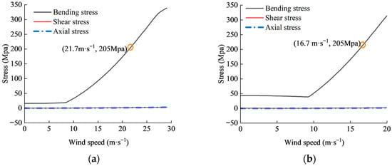
Figure 9.
Maximum bending, axial, and shear stresses in frames under load combination 1: (a) 8.0 m span plastic greenhouse; (b) 9.5 m span plastic greenhouse.
At the wind speeds of va, both the 8.0 m span and the 9.5 m span pipe frames exhibited inward deformations in the windward sections and outward deformations in the leeward sections (Figure 10). These deformation characteristics align with those in the study conducted on a similar frame [27]. Additionally, the maximum deformations of the 8.0 m span and the 9.5 m span frames were 48 and 89 mm, respectively. The results indicated that the 8.0 m span frame could withstand higher wind loads and had better stiffness compared with the 9.5 m span frame.
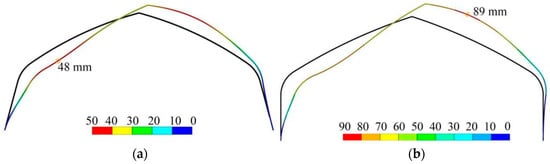
Figure 10.
Deformations of frames under load combination 1 (magnified tenfold for clarity): (a) 8.0 m span plastic greenhouse; (b) 9.5 m span plastic greenhouse. Black line represents the undeformed frame, while the colored line represents the deformed frame.
3.3. Wind-Bearing Capacity of Frames Under Load Combination 2
When utilizing a plastic greenhouse for cultivating fruit vegetables, it is essential to evaluate the effects of crop loads on the structural safety of the frames. The ‘wind speed–displacement’ curves for the windward eave of the 8.0 m span and 9.5 m span frames under load combination 2 are shown in Figure 11. For the 8.0 m span frame, the behaviors of the curve were similar to those observed under load combination 1, but with a reduced growth rate in the central segment of the curve. Moreover, the curve of the 9.5 m span frame followed a logarithmic function form and was inclined to experience buckling at a wind speed over 20.2 m·s−1. This behavior exhibited by the curve aligns with that observed in the frames under the wind and snow loads [11,27]. The results also indicated that the vertical component of the crop load amplified the P-Δ effects and accelerated the lateral deformation of the frame, further reducing its wind-bearing capacity and revealing a tendency toward buckling.
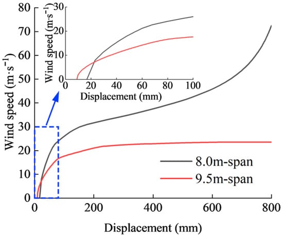
Figure 11.
‘Wind speed–displacement’ for windward eave of frames under load combination 2.
By examining the local magnification of Figure 12, the ‘wind speed–displacement’ curve varies following a logarithmic function form when the displacement is below 1% of the span. There are no sharp inclines in the curves. Thus, the frames remained structurally stable within the aforementioned range of displacements. On the other hand, the bending moment is the main internal force exerted on the frames under these conditions, as both the maximum axial and shear stresses are lower than the bending stresses and well below the yield strength of the steel tubes. Then, the va values for the 8.0 m span frame and 9.5 m span frame under load combination 2 are 15.5 and 12.8 m·s−1, respectively. Both va values are lower compared to those under load combination 1. Consequently, the addition of crop loads did not alter the dominant type of internal force when the windward eave horizontal displacements were below 1% of the span, but reduced the va.
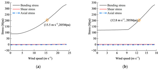
Figure 12.
Maximum bending, axial, and shear stresses in frames under load combination 2: (a) 8.0 m span plastic greenhouse; (b) 9.5 m span plastic greenhouse.
At the wind speeds of va, both frames exhibit an inward deformation on both sides and an upward protrusion of the ridge (Figure 13). The windward side exhibits a greater extent of inward deformation towards the interior compared to the leeward side due to the influence of wind pressure and the forces from crop loads acting on the windward eaves. The maximum total deformations for the 8.0 m and 9.5 m span frames under load combination 2 are 51 and 96 mm, respectively. All these maximum total deformations were observed near the ridge on the leeward roof.
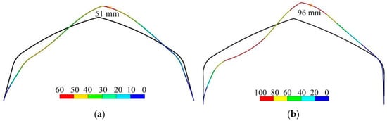
Figure 13.
Deformations of frames under load combination 2 (magnified by 10 times): (a) 8.0 m span plastic greenhouse; (b) 9.5 m span plastic greenhouse.
In summary, the crop loads have adverse effects on the wind-bearing capacity of the frames.
3.4. Effects of Pipe Cross-Section on Wind-Bearing Capacity of 9.5 m Span Frame
Figure 14 plots va against the section modulus of the square, elliptical, and oval pipes. The results indicated a positive relationship between va and the section modulus. Thus, it is preferred to select the pipes with a cross-section that offers a larger section modulus. From a mechanical perspective, this correlation indicates that a higher section modulus implies lower bending stress, thereby enhancing the arch’s resistance to bending moments and improving its overall flexural performance. Moreover, the va for the 9.5 m span frame was not improved by substituting the circular pipe with the square, elliptical, or oval pipes of the similar cross-sectional area, since the section modulus of the circular pipe was largest. In the following analysis, the frame constructed with the circular pipe was used continuously.
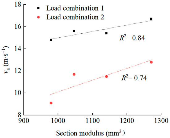
Figure 14.
Allowable wind speed (va) plotted against section modulus of pipes with hollow circle, square, elliptical, and oval cross-sections for 9.5 m span frame.
3.5. Effects of Anchoring Reinforcement Cables on Wind-Bearing Capacity of 9.5 m Span Frame
Increasing the sectional dimension of pipes is a common strategy to enhance the wind-bearing capacity of the frame. However, it is important to note that this approach can lead to higher construction costs and diminish overall economic benefits due to the fact that the bending stresses in most of the frame components are significantly lower than the allowable stress.
Figure 15 illustrates the relationship between wind speed and the horizontal displacement of the windward eave for the 9.5 m span reinforced frame. Under load combination 1, the frame initially deforms outward at the shoulders due to permanent loads, resulting in a relaxed state of the reinforcement cables. As the wind speed increases, the cables gradually tighten and begin to restrain further deformation of the frame. In contrast, under load combination 2, the presence of crop loads causes the reinforcement cables to be taut from the outset, thereby limiting the frame deformation from the beginning. These curves indicate that the reinforced frames did not show any buckling failure within the horizontal displacement range of the windward eaves under both load combination 1 and 2. The results indicated that the cables act as a strong lateral constraint that restricts the displacement of the windward eave. As a result, the P-Δ effect moments amplified by crop loads were limited and thus avoided the increment of lateral displacement.
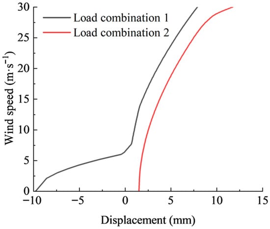
Figure 15.
‘Wind speed–displacement’ for windward eave of the reinforced 9.5 m span frame.
Both the shear forces and axial forces generated in the frame increased, but were still lower than the maximum bending stresses (Figure 16). Thus, the frame was still primarily affected by bending moments. The va of the reinforced frame under load combinations 1 and 2 were 25.6 m·s−1 and 21.2 m·s−1, respectively. Both were higher than those observed in the 8.0 m span and 9.5 m span frames. At those moments, the reinforced frame deformed with a concave windward roof and a convex leeward roof under both load combinations. However, the maximum total deformation was 44 mm under load combination 1 and occurred at the leeward roof, while it was 40 mm under load combination 2 and occurred at the windward roof (Figure 17). The results further confirmed that the crop loads could weaken the wind-bearing capacity of the frame. It is also worth noting that the maximum bending moment occurs at the junctions of the windward reinforcement cable and the apex of the side column. Measures should be taken to strengthen this junction.
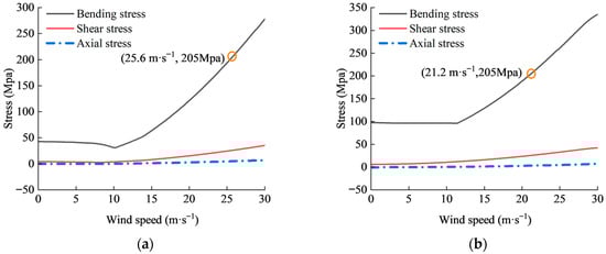
Figure 16.
Maximum bending, axial, and shear stresses in the reinforced frame: (a) load combination 1; (b) load combination 2.
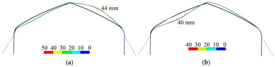
Figure 17.
Deformations of 9.5 m span reinforced frame: (a) load combination 1; (b) load combination 2.
3.6. Stability Analysis Considering Initial Geometric Imperfection
As mentioned previously, the vertical loads are transferred from the frames to the ground through the side columns. The application of crop loads further increases these transmitted vertical loads and thereby increases the risk of buckling deformations in the side columns. Therefore, stability analysis is performed on the 9.5 m span and the reinforced frames, considering the introduction of initial geometric imperfections into the side columns.
Figure 18 illustrates the ‘wind speed–displacement’ curves of the 9.5 m span and reinforced frames under load combination 2. For the 9.5 m span frame with initial geometric imperfections, the eave displacement accumulates significantly faster than that of the perfect frame. The va and the critical buckling wind speed for the 9.5 m span frame were observed to be 11.0 and 22.0 m·s−1, respectively. These values were 1.1 and 1.7 m·s−1 lower than those of an ideal frame. In contrast, for the reinforced frame, no instances of structural buckling were observed within the wind speed range of up to 30 m·s−1. The va for this frame was 20.4 m·s−1, which was 10.3 m·s−1 higher than that of the imperfect 9.5 m span frame and only 0.6 m·s−1 lower than that of the ideal reinforced frame. These results further demonstrate that initial geometric imperfections exacerbate P-Δ effects and significantly decrease the va for the 9.5 m span frame. In contrast, the anchored cables provide critical lateral stiffness and effectively limit deformation, successfully mitigating the reduction in va. This confirms that suppressing deformation is the most effective strategy for inhibiting the amplification of P-Δ effects induced by initial geometric imperfections.

Figure 18.
‘Wind speed–displacement’ for windward eave of 9.5 m span and reinforced frames under load combination 2.
4. Discussion
Plastic greenhouse frames are typically anchored by embedding their bottoms into the ground. This kind of constraint can be categorized as either hinged or fixed support. The Chinese code GB/T 51183-2016 [29] does not provide clear requirements on this issue. However, the Japanese code [30] stipulates that the above constraint could be deemed as a fixed support if the bottoms of the frames are embedded at least 400 mm into the ground. Moreover, the studies conducted by Takahashi and Uematsu [27], Toyoda et al. [8], Ding et al. [11], and Wang et al. [25] set the support as a fixed type. Therefore, in this study, supports of the 8.0 m span and 9.5 m span frame bottoms are assumed to be fixed supports. The connection type of the frame components is another topic of ongoing discussion. Ha et al. [22] argued that the connection of structural components of a multi-span plastic vaulted greenhouse is non-rigid. Conversely, the study on a plastic greenhouse found that the type of frame component connection minimally impacts the correlation between wind pressure and the horizontal displacement of the windward side-column apex [8]. Consequently, the connections of frame members were ultimately considered as rigid connections.
The structural behavior of the arch under wind loads is summarized in Table 4. The trends of the ‘wind speed–displacement’ curves of the 8.0 m span and 9.5 m span frames achieved under load combination 1 align with the findings from the studies conducted with similar plastic greenhouses [11,27]. However, the studies conducted with a pitched two-span plastic greenhouse [8] and a large-span plastic greenhouse frame with a truss structure [12] exhibited load–displacements curves that follow a logarithmic function. This difference suggests that the curve trends of the displacement–load can vary based on the frame shape. On the other hand, both frames primarily bear bending moments under load combinations 1 and 2. These findings are consistent with the research conducted on comparable single-span plastic greenhouses, which used frames constructed with single pipes [2,7]. The reduction in va for the 9.5 m span frame compared to that in the 8.0 m span frame can be ascribed to the degradation of lateral stiffness due to the structural dimension increment. This lower initial stiffness made the 9.5 m span undergo rapid and larger lateral displacements, which finally induced larger moment stresses. As a result, the va for the 9.5 m span frame decreased by 23%.
Table 4.
Comparison between the simulation results of this study and the literature data.
According to the simulation results, both crop loads and initial geometric imperfections have detrimental effects on the wind-bearing capacity of the frames. Under these conditions, the frames still tend to experience strength failure under wind loads rather than stability failure. On the other hand, Maraveas and Tsavdaridis [5] observed that the unexpected loss of stiffness in local bracing members could induce severe second-order deformations and ultimately lead to a ‘domino-effect’ collapse. Similarly, crop loads and initial geometric imperfections amplify the P-Δ effect and decrease va.
The linear correlation between va and the section modulus of the pipes further indicates that the pipes with a larger section modulus help decrease the bending moment stress and increase the wind-bearing capacity of frames. Therefore, when the cross-sectional areas are similar, it is advisable to select pipes with a higher section modulus for constructing the frame. Moreover, restricting displacement is essential for preventing wind-induced buckling in this study [5]. The installation of side cables on the 9.5 m span frame introduces a strong lateral constraint and fundamentally alters the stiffness characteristics of the large-span frame. It also helps cut off the feedback loop of the P-Δ effects induced by crop loads and initial geometric imperfections and increase va under those conditions.
Existing research shows that the structural deformation and stress induced by dynamic wind loads can be significantly higher than those produced by static mean wind loads [8,17]. Li et al. [18] recommend introducing a wind vibration coefficient to convert static loads into equivalent dynamic wind loads. Although the 10 min mean wind speed was replaced by the 3 s gust wind speed in GB/T 51183-2016, it remains uncertain whether this substitution can fully represent the dynamic amplification. Moreover, μs is a key parameter to determining wind loads. Its value may differ from the standards and can vary with the shape of plastic houses [19]. Future work should incorporate a more accurate μs to reflect the actual wind pressure distribution.
This study employed a two-dimensional (2D) plane-frame model to evaluate the wind-bearing capacity of the frames. According to Takahashi and Uematsu [27], compared to the three-dimensional (3D) model analyses, 2D analyses neglect the restraining effects of horizontal tie beams and therefore tend to predict larger lateral displacements under transverse wind loads when the horizontal displacement at the windward eaves is less than approximately 900 mm. As a result, the assessment of frame stability and the failure limits determined in this study can be regarded as conservative. On the other hand, Morikawa et al. [34] reported that longitudinal wind could cause the windward gable wall to incline and trigger a progressive “domino-effect” collapse. In practice, supporting pipes are conventionally installed to prevent such inclination and to mitigate the out-of-plane failure of the frames. For this reason, the present study focuses on transverse wind effects. Nevertheless, future work should incorporate a full 3D model to accurately capture the structural response of frames to wind loads.
5. Conclusions
This study conducted a comparative analysis of the wind-bearing capacities of the newly designed 9.5 m span frame and the standard 8.0 m span frame, revealing the mechanism by which structural dimension increments degrade structural stiffness. Furthermore, the study clarified the influences of crop loads and pipe cross-sections on the failure process and validated the effectiveness of cable reinforcement in suppressing lateral deformation and enhancing wind-bearing capacity. Based on the numerical simulations and theoretical analysis, the conclusions are as follows:
(1) The 9.5 m span frame exhibits a lower initial stiffness compared to the 8.0 m span frame, which leads to a rapid increase in lateral deformation under wind loads, consequently leading to a significantly lower va.
(2) The presence of crop loads and initial geometric imperfections could accelerate frame deformation via P-Δ effects, and increase internal bending stresses, which further reduce va.
(3) Simulation results indicate that the arch frame exhibits strength failure when subjected to wind loading and primarily bears bending stresses. Accordingly, the va exhibits a positive linear correlation with the section modulus of the pipe.
(4) Installing reinforcement cables could limit the lateral deformation of the frames and cut off the amplification of P-Δ effects induced by crop loads and initial geometric imperfections, thereby significantly increasing the va of the 9.5 m span frame. Thus, limiting lateral displacement through reinforcement measures can markedly increase the wind-bearing capacity of frames.
(5) This study relied on a quasi-static nonlinear analysis that incorporated a 2D structural model, substituted dynamic wind effects with a 3 s gust wind speed, and adopted standardized values of μs. Future work should incorporate a full 3D model, dynamic wind loading, and more accurate wind pressure coefficients to obtain more reliable results.
(6) The reinforced 9.5 m span frame demonstrates sufficient structural integrity under strong winds. It is therefore considered a feasible and superior alternative to the standard 8.0 m span frame for meeting the modern demands of facility agriculture in Southern China.
Author Contributions
Conceptualization, M.L. and T.Z.; software, M.L., H.M. and H.L.; investigation, M.L. and H.L.; data curation, H.M.; writing—original draft preparation, M.L.; writing—review and editing, T.Z. and M.L.; visualization, M.L.; supervision, T.Z. All authors have read and agreed to the published version of the manuscript.
Funding
This research was supported by the Major Science and Technology Special Project of Henan Province (Grant No. 241100110200).
Data Availability Statement
The data presented in this study are available in this article.
Conflicts of Interest
The authors declare no conflicts of interest.
References
- Briassoulis, D.; Dougka, G.; Dimakogianni, D.; Vayas, I. Analysis of the collapse of a greenhouse with vaulted roof. Biosyst. Eng. 2016, 151, 495–509. [Google Scholar] [CrossRef]
- Kim, R.; Lee, I.; Yeo, U.; Lee, S. Evaluation of various national greenhouse design standards for wind loading. Biosyst. Eng. 2019, 188, 136–154. [Google Scholar] [CrossRef]
- Moriyama, H.; Sase, S.; Okushima, L.; Ishii, M. Which design constraints apply to a pipe-framed greenhouse? From perspectives of structural engineering, meteorological conditions, and wind engineering. Jpn. Agric. Res. Q. JARQ 2015, 49, 1–9. [Google Scholar] [CrossRef]
- Ryu, H.; Choi, M.; Cho, M.; Yu, I.; Kim, S. Damage index estimation by analysis of meteorological disasters on film plastic greenhouses. Int. J. Agric. Biol. Eng. 2019, 12, 58–63. [Google Scholar] [CrossRef]
- Maraveas, C.; Tsavdaridis, K.D. Assessment and Retrofitting of an Existing Steel Structure Subjected to Wind-Induced Failure Analysis. J. Build. Eng. 2019, 23, 53–67. [Google Scholar] [CrossRef]
- Saglam, C.; Guzel, M.; Cetin, N. A greenhouse construction with fiber-reinforced plastic chords and triangular pyramid models. Fresenius Environ. Bull. 2018, 27, 9447–9452. [Google Scholar]
- Wang, C.; Xu, Z.; Jiang, Y.; Wang, T. Numerical analysis of static and dynamic characteristics of large-span pipe-framed plastic greenhouses. Biosyst. Eng. 2023, 232, 67–80. [Google Scholar] [CrossRef]
- Toyoda, H.; Moriyama, H.; Seno, T.; Maekawa, T. Examples and Characteristics of wind damages on plastic greenhouses. J. Soc. Agric. Struct. 1998, 29, 21–30. [Google Scholar] [CrossRef]
- Takahashi, K.; Uematsu, Y. Collapse processes of pipe-framed greenhouses under wind or snow loads. J. Soc. Agric. Struct. 2016, 47, 1–8. [Google Scholar] [CrossRef]
- Lei, X.; Lv, X.; Lu, D.; Zhang, M.; Xia, L. Wind and snow load analysis of agricultural plastic greenhouses with steel frames in the Jiangsu-Zhejiang region. Jiangsu Agric. Sci. 2018, 46, 185–188. [Google Scholar] [CrossRef]
- Ding, M.; Li, M.; Shi, X.; Zhang, P.; Jiang, X. Stable bearing capacity calculation of greenhouse structures considering skin effect of covering material. Trans. Chin. Soc. Agric. Eng. 2016, 32 (Suppl. S1), 224–232. [Google Scholar] [CrossRef]
- Ren, J.; Wang, J. Finite element analysis of the static properties and stability of a large-span plastic greenhouse. Comput. Electron. Agric. 2019, 165, 104957. [Google Scholar] [CrossRef]
- Sim, V.; Jung, W. Wind Fragility of Steel and Carbon-Fiber Reinforced Plastic Single-Span Greenhouses. J. Korean Soc. Adv. Compos. Struct. 2020, 11, 18–24. [Google Scholar] [CrossRef]
- Lee, J.Y.; Ryu, H.R. Structural Analysis of Pipe-Framed Greenhouses Using Interface Elements for Cross-Over Connections. Eng. Struct. 2023, 266, 114504. [Google Scholar]
- Jeon, J.; Kim, S.; Kim, T. Structural Safety Changes and Reinforcement Effect of Raising the Height of Korean Plastic Greenhouses. Hortic. Sci. Technol. 2025, 43, 198–211. [Google Scholar] [CrossRef]
- Xie, H.; Wei, C.; Zheng, X.; Xu, W. Wind-Induced Response Analysis of Flat-Elliptical Pipe Skeleton Plastic Greenhouse Considering Dynamic Wind Effects. Sci. Rep. 2025, 15, 37024. [Google Scholar] [CrossRef]
- Jiang, Y.; Bai, Y.; Wang, C.; Wang, Y.; Pang, X. Dynamic response analyses of plastic greenhouse structure considering fluctuating wind load. Adv. Civ. Eng. 2021, 2021, 8886557. [Google Scholar] [CrossRef]
- Li, X.; Wang, C.; Jiang, Y.; Bai, Y. Dynamic Response Analysis of a Whole Steel Frame Solar Greenhouse under Wind Loads. Sci. Rep. 2022, 12, 5200. [Google Scholar] [CrossRef] [PubMed]
- Maraveas, C. Wind Pressure Coefficients on Greenhouse Structures. Agriculture 2020, 10, 149. [Google Scholar] [CrossRef]
- Fernández-García, M.S.; Vidal-López, P.; Rodríguez-Robles, D.; Villar-García, J.R.; Agujetas, R. Numerical simulation of multi-span greenhouse structures. Agriculture 2020, 10, 499. [Google Scholar] [CrossRef]
- Hur, D.; Noh, J.; Lee, H.; Song, H. Evaluation of stress distribution with wind speed in a greenhouse structure. Wind Struct. 2018, 27, 347–356. [Google Scholar] [CrossRef]
- Ha, T.; Kim, J.; Cho, B.; Kim, D.; Jung, J.; Shin, S.; Kim, H. Finite element model updating of multi-span greenhouses based on ambient vibration measurements. Biosyst. Eng. 2017, 161, 145–156. [Google Scholar] [CrossRef]
- Liu, X.; Li, Z.; Zhang, L.; Liu, Y.; Li, Y.; Li, T. Effect of single tube sections on the structural safety of Chinese solar greenhouse skeletons. Sci. Rep. 2021, 11, 19307. [Google Scholar] [CrossRef]
- Li, M.; Zhou, C.; Yan, J.; Zhang, Q.S.; He, F.; Yin, Y.L. Review on anti-wind technologies of plastic greenhouse in Japan. J. Chin. Agric. Mech. 2016, 37, 46–53. [Google Scholar] [CrossRef]
- Wang, C.; Jiang, Y.; Wang, T.; Xu, Z.; Bai, Y. Analysis of wind-induced responses of landing assembled Chinese solar greenhouses. Biosyst. Eng. 2022, 220, 214–232. [Google Scholar] [CrossRef]
- Maraveas, C.; Tsavdaridis, K.D. Strengthening Techniques for Greenhouses. AgriEngineering 2020, 2, 37–54. [Google Scholar] [CrossRef]
- Takahashi, K.; Uematsu, Y. Collapse process and reinforcement effects of pipe-framed greenhouses under snow loading based on a 3-D analysis. J. Soc. Agric. Struct. 2018, 49, 157–163. [Google Scholar] [CrossRef]
- Dong, X.; Piao, F.; Du, N.; Dong, H.; Zhang, T.; Qin, Y.; Li, Y.; Guo, Z. Optimization of Structural Configuration and Ridge Height for Large-Span Insulated Plastic Greenhouse Based on Finite Element Analysis. Agriculture 2025, 15, 1333. [Google Scholar] [CrossRef]
- GB/T 51183-2016; MOHURD. Code for the Design Load of Horticultural Greenhouse Structures. China Planning Press: Beijing, China, 2016. (In Chinese)
- JGHA Standard; Japan Greenhouse Horticulture Association. Standard for Structures of Greenhouses. Japan Greenhouse Horticulture Association: Tokyo, Japan, 1999. (In Japanese)
- Zhou, J.; Su, J. Detailed Analysis Examples of ANSYS Workbench Finite Element Analysis Statics; Posts and Telicommunications Press: Beijing, China, 2017; pp. 355–367. [Google Scholar]
- Roux, P.; Robertson, A.P.; Motro, R. The design of slender monotubular steel arches. Struct. Eng. 1997, 75, 143–151. [Google Scholar]
- GB 50017-2017; Standard for Design of Steel Structures. China Architecture & Building Press: Beijing, China, 2017. Available online: http://jncc.jinan.gov.cn/attach/0/c24799cca3194d3ba1d87c72caa1c3ef.pdf (accessed on 12 December 2017). (In Chinese)
- Morikawa, K.; Takao, H.; Suda, A.; Nobayashi, T.; Enoki, S.; Muromaki, T.; Yoshioka, T. A Study for Wind Damage in Greenhouse Horticulture (Examination by Analysis Using 3D Model). Available online: https://www.nara-k.ac.jp/nnct-library/publication/pdf/kiyo_r2_3.pdf (accessed on 30 November 2025).
Disclaimer/Publisher’s Note: The statements, opinions and data contained in all publications are solely those of the individual author(s) and contributor(s) and not of MDPI and/or the editor(s). MDPI and/or the editor(s) disclaim responsibility for any injury to people or property resulting from any ideas, methods, instructions or products referred to in the content. |
© 2025 by the authors. Licensee MDPI, Basel, Switzerland. This article is an open access article distributed under the terms and conditions of the Creative Commons Attribution (CC BY) license (https://creativecommons.org/licenses/by/4.0/).