Abstract
Accurate seismic safety assessment of nuclear power plant (NPP) structures with pile foundations on soft soil sites requires consideration of soil nonlinearity and pile–soil–structure interaction (PSSI). This study develops an efficient partitioned SSI framework, where the nonlinear soil response is simulated using the Davidenkov skeleton curve combined with a modified Masing rule and solved by an explicit time integration scheme, while the structural dynamics are evaluated using the modal superposition method. The framework is applied to a pile-supported CAP1400 NPP model on deep soft soil, with both piles and the superstructure modeled as elastic. Two computational schemes are examined: (a) explicit integration of the soil while treating the piles and structure as an integrated system analyzed via modal superposition; and (b) explicit integration of both soil and piles, with the structure analyzed using modal superposition. Under pulse excitation, both schemes yield comparable dynamic responses, whereas scheme (b) improves computational efficiency by over threefold (88 h vs. 293 h). Results using scheme (b) under RG1.60 excitation show that soil nonlinearity reduces and delays structural responses but increases pile bending moments and stress concentration, demonstrating the framework’s effectiveness and practicality for nonlinear SSI analysis of NPP structures.
1. Introduction
For the sake of seismic safety and cooling reliability, most existing pressurized water reactor NPPs are constructed on coastal sites with favorable geological conditions and competent bedrock foundations []. As nuclear power continues to expand, suitable coastal bedrock sites are becoming increasingly limited, and future NPPs are likely to be located in inland regions characterized by more complex geological conditions, including soft-soil deposits. Compared with bedrock or stiff-soil sites, soft soils typically exhibit lower bearing capacity, higher compressibility, and stronger amplification of ground motion, which may result in excessive settlement and reduced seismic performance of superstructures []. To address these challenges, pile foundations have been widely adopted in NPP engineering, as they enhance the bearing capacity of the subsoil, reduce overall settlement, and improve the global seismic performance of nuclear structures [,,]. Consequently, pile-supported foundations show significant potential for inland nuclear projects, particularly in deep soft-soil areas.
Under seismic excitation, the dynamic response of nuclear structures is strongly influenced by pile–soil–structure interaction (PSSI), in which both inertial and kinematic components play important roles [,]. The inertial component is generated by the superstructure motion, while the kinematic component arises from soil nonlinearity and seismic wave propagation [,]. For large-scale NPPs with massive superstructures and deep pile groups, these coupled mechanisms become highly complex due to the spatial variability of soil properties and the interactions within the pile group. Neglecting soil nonlinearity can lead to overestimation of high-frequency acceleration and underestimation of energy dissipation, causing notable deviations in the computed structural responses [,]. Accurate representation of nonlinear soil behavior is therefore essential for reliable seismic response assessment and maintaining appropriate safety margins.
Numerous experimental and numerical studies have focused on understanding PSSI in nuclear structures. Physical investigations, including centrifuge modeling and shaking table testing [,,], have provided valuable insights into the dynamic behavior of pile-supported NPP foundations, but their application is constrained by high cost, limited model scale, and challenges in reproducing in situ soil conditions. Frequency-domain substructure methods, such as CLASSI, SASSI, and ACS-SASSI, are computationally efficient and widely used in engineering practice [,,]. However, these methods assume linear or weakly nonlinear soil behavior, restricting their applicability for soft or highly nonlinear deposits [,,]. Direct time-domain approaches have been developed to more realistically capture material nonlinearity, contact separation, and hysteresis. Although these methods are effective in representing nonlinear effects, their computational demand becomes prohibitive for large NPP systems with hundreds of thousands or even millions of degrees of freedom (DOFs) [,,]. Balancing numerical efficiency and adequate representation of nonlinear soil behavior remains a key challenge in practical SSI simulations.
Various constitutive models have been proposed to represent nonlinear and hysteretic soil behavior [], including the Ramberg–Osgood model, the Hardin–Drnevich model, bounding surface plasticity formulations, and nonlinear viscoelastic models [,,]. While suitable for element-scale or small-scale analyses, these models often require extensive parameter calibration and iterative matrix operations in implicit solvers, limiting their efficiency in large three-dimensional SSI applications []. Moreover, many conventional models cannot fully reproduce experimentally observed hysteretic damping and modulus degradation of soft cohesive soils subjected to large cyclic strains [,,]. These limitations highlight the need for simplified yet physically representative soil models that can be efficiently applied in large-scale dynamic simulations.
To improve computational efficiency while maintaining nonlinear accuracy, several hybrid and partitioned frameworks have been developed [,]. These typically couple equivalent-linear analysis for the far-field soil with nonlinear modeling of the near-field foundation zone. Their applicability is limited, however, when strongly coupled pile-group behavior or multi-structure interaction within NPP complexes is considered. To address these challenges, Chen et al. proposed the Parallel Analysis of Soil–Structure Interaction (PASSI) framework, which uses an explicit–implicit coupling strategy to efficiently analyze large-scale SSI problems [,]. Lv and Chen further extended this framework for nonlinear SSI simulations of NPP structures []. In PASSI, the unbounded soil domain is modeled using an explicit lumped-mass finite element formulation with a transmitting artificial boundary, while nonlinear soil behavior is represented using a viscoelastic constitutive relationship. The structural domain is analyzed using an implicit integration scheme with Rayleigh damping, and the two subsystems are coupled through synchronized exchange of interface forces and displacements. This approach achieves high parallel efficiency and scalability while preserving physical consistency between soil and structure responses.
Although PASSI has demonstrated considerable efficiency, its application to pile-supported NPP structures involving hysteretic soil nonlinearity has not been extensively explored. Additionally, the influence of different partitioning strategies—particularly the allocation of soil, pile, and superstructure domains between explicit and modal solvers—has received limited systematic investigation for large NPP models. Motivated by these gaps, the present study investigates PASSI-based partitioned strategies for nonlinear PSSI analysis.
Building on the PASSI framework, an efficient partitioned parallel method is developed for nonlinear SSI analysis of pile-supported NPP structures. The soil domain is modeled using an explicit integration scheme incorporating nonlinear behavior derived from the Davidenkov skeleton curve combined with a modified Masing rule [,], enabling realistic representation of hysteretic damping and modulus degradation. The structural domain, including the foundation and superstructure, is analyzed using the modal superposition method to efficiently evaluate dynamic response under linear assumptions. Two explicit–modal partitioning strategies are considered: (a) the soil domain is solved explicitly, while the pile–structure system is modeled as an integrated body using modal superposition; (b) the soil and piles are solved together using explicit integration, while the superstructure is analyzed through modal superposition.
The main contributions of this work are summarized as follows: (1) A nonlinear explicit soil model based on the Davidenkov–Masing formulation is incorporated into PASSI, providing a practical approach to simulate soil hysteresis in large-scale SSI analyses while maintaining high computational efficiency. (2) An explicit–modal partitioned coupling strategy tailored for pile-supported NPP structures is developed, enabling efficient treatment of soil nonlinearity and structural dynamics. (3) Two computational schemes are systematically evaluated under pulse-type and earthquake excitations, offering quantitative insights into accuracy, efficiency, and engineering applicability for large-scale nonlinear PSSI simulations.
The paper is structured as follows. Section 2 presents the theoretical formulation and implementation of the proposed nonlinear partitioned SSI method. Section 3 introduces the CAP1400 case study, compares the two partitioning schemes under pulse excitation, and applies the more efficient scheme to earthquake input. Section 4 summarizes the conclusions.
2. Methodology and Implementation
As illustrated in Figure 1, SSI analysis of NPP structures with pile foundations considering soil nonlinearity can be regarded as a seismic wave scattering problem involving the dynamic coupling between the structure and the surrounding semi-infinite medium []. For numerical implementation, the infinite domain is truncated into a finite computational region, and artificial boundaries are introduced to simulate wave radiation effects. The overall procedure consists of three main components: (1) Free-field analysis to determine input ground motions; (2) Artificial boundary modeling to ensure proper wave transmission; and (3) SSI analysis to capture the coupled dynamic response. To achieve both accuracy and computational efficiency, a partitioned SSI framework is adopted. In this framework, the soil domain is solved using an explicit time integration scheme that incorporates nonlinear soil behavior, while the structural domain is analyzed using the modal superposition method. The coupling between the two subdomains is performed through synchronized exchange of interface information at each time step. In addition, a parallel domain-decomposition strategy is employed to further enhance computational performance. The detailed formulation and implementation of each component are presented in the following subsections.
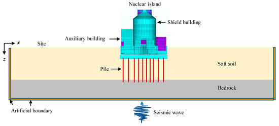
Figure 1.
The SSI analysis model for NPP with pile foundations.
2.1. Seismic Input for Model Boundaries
Before conducting the SSI analysis, the free-field motions along the artificial boundaries of the soil model must be obtained. The far field is assumed to consist of horizontally layered soil, as shown in Figure 2. Wave propagation in a semi-infinite medium composed of n parallel, homogeneous, and isotropic layers is computed using the propagator matrix method. Given the motion at the control point, the free-field response along the soil column is obtained by specifying the wave type and incident angle, and the time-domain motions are recovered through inverse Fourier transformation [,,]. To account for the primary nonlinear behavior of the soil, an equivalent linearization approach is adopted []. The shear modulus and damping ratio of each soil layer are iteratively updated using strain-compatible values derived from the modulus reduction and damping curves. This iterative procedure provides an effective representation of soil nonlinearity under seismic loading while maintaining computational numerical stability.
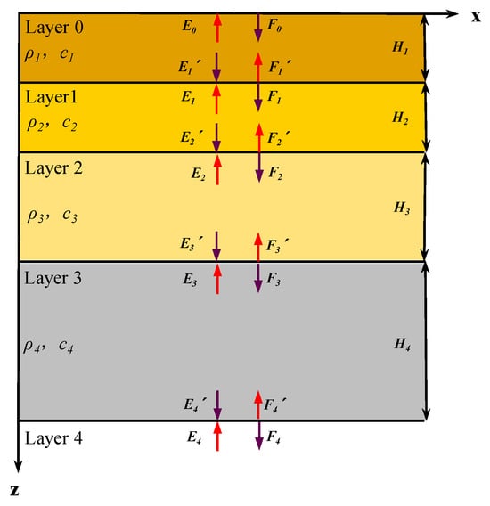
Figure 2.
The Free-field analysis model.
At the base and lateral boundaries of the soil domain, the multi-transmitting formula (MTF) boundary is implemented to simulate wave radiation and energy dissipation in the far field []. The time-domain displacement responses obtained from the free-field analysis at the boundary nodes are then extracted and applied as input motions for the subsequent SSI simulations.
2.2. Motions of the Soil Nodes
As shown in Figure 3, the SSI system of NPP is divided into two computational partitions. The soil is modeled using lumped-mass finite elements, and its motion is solved by explicit integration. The soil nodes are categorized into three groups: internal nodes (including free-surface nodes), interface nodes, and artificial boundary nodes.
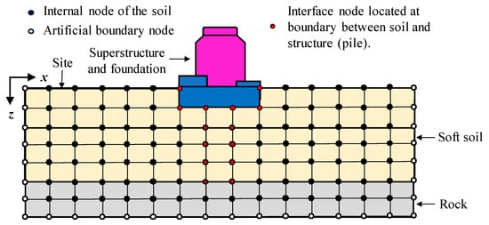
Figure 3.
Classification of soil nodes within the site model and spatial distribution of the interface nodes.
2.2.1. Motions of the Internal Nodes
Under seismic excitation, the soil exhibits nonlinear behavior, with its shear modulus progressively decreasing as strain develops. This degradation further amplifies the subsequent strain response, causing the shear modulus to vary throughout the loading process and necessitating continuous updates during analysis. To avoid iterative nonlinear computations, the nonlinear soil response is represented using an incremental equilibrium equation [], in which the tangent shear modulus is adopted and updated at each time step.
The transient response is computed using an explicit time integration scheme. The equation of motion is expressed as:
where , , and represent the incremental acceleration, velocity, and displacement of node i, respectively; denotes the incremental external load acting on node i; is the mass matrix associated with node i, which remains constant during the analysis; and are the damping and stiffness matrices of node i, respectively. The stiffness matrix is expressed as
where is the strain–displacement matrix; and is the constitutive matrix determined by the current secant shear modulus of the soil, which is expressed as
where is the shear modulus and is the Poisson’s ratio of the soil. The additional damping is represented by a Rayleigh damping model, and the damping matrix is given as
where and are the Rayleigh damping coefficients, which depend on the material damping ratio and the predominant frequency of the input motion. Assuming that the Poisson’s ratio remains constant during deformation, the nonlinear soil behavior is captured by updating the shear modulus and damping ratio at each time step.
At time , the acceleration and velocity are expressed in terms of the displacements at times , , and using the central difference approximation:
where , , and are the incremental displacement vectors at times , , and , respectively, and is the time step. Substituting the above difference approximations into the equation of motion yields the incremental displacement at time , which can be written as:
The procedure for computing the nonlinear soil displacement is summarized in Table 1. In Steps (2)–(3), the shear modulus is updated at each time step, and an appropriate constitutive model can be selected based on the soil type and its dynamic properties. In this study, the nonlinear soil behavior is represented using a modified Davidenkov model combined with a simplified loading–unloading rule.

Table 1.
Procedure for nonlinear soil displacement computation.
2.2.2. Modified Davidenkov Constitutive Model and Simplified Hysteretic Rule
Martin et al. apply the Davidenkov constitutive model to simulate the nonlinear behavior of soil, which describes the relationship among shear modulus, shear stress, and shear strain []. The model can be expressed as:
where is the shear strain, is the shear stress, is the reference shear strain, and is the initial shear modulus. The parameters and denote the shape and curvature parameters of the model, respectively.
Figure 4 illustrates the hysteresis loops of the modified Davidenkov model under irregular cyclic loading. While the traditional Masing rule can capture the hysteretic behavior of soils under uniform cyclic loading, irregular loading induces lag and additional nonlinearity in the stress–strain response, necessitating modifications to the original hysteresis curve. Pyke’s “factor-of-two” approach offers one means to adjust the Davidenkov hysteresis curve [], but it requires numerous state parameters, complicating implementation. To overcome this, Zhao et al. propose a simplified modified loading–unloading rule that is better suited for numerical simulations [,,].
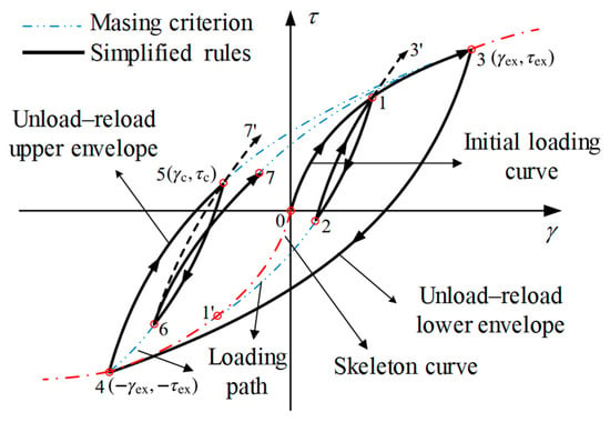
Figure 4.
Davidenkov model with irregular loading-reloading rules.
As shown in Figure 4, the stress–strain evolution of the modified Davidenkov model can be divided into three stages:
- Initial loading stage: The stress–strain response follows the skeleton curve, as described by Equation (7).
- Stress reversal stage: When the soil stress changes direction—such as at segments , , and —the subsequent loading path evolves from the reversal point toward the historical maximum (or minimum) stress. The corresponding stress–strain relationship is expressed aswhere and are the stress and strain at the reversal point, respectively. The hysteretic curve following stress reversal is obtained by amplifying the initial skeleton curve by a factor of n.
- Intersection with the skeleton curve: When the loading–unloading path intersects the skeleton curve before stress reversal, the subsequent hysteretic curve follows the extended Masing rule along the upper skeleton branch.
Using this framework, it is sufficient to track only the extreme points (e.g., points 3 and 4 in Figure 4) and reversal points (e.g., points 2 and 6 in Figure 4) in the loading history to accurately reproduce the soil stress–strain response under irregular cyclic loading.
Differentiating Equation (7) with respect to shear strain yields the tangent shear modulus along the initial skeleton curve:
Similarly, differentiating Equation (8) with respect to shear strain gives the tangent modulus along the hysteretic curve:
In Equation (10), is determined by the inflection point and the historical loading–unloading extrema:
In Equation (11), the sign “+” is taken for the loading process, while “–” is taken for the unloading process. By substituting the inflection point and the historical loading–unloading extrema into Equation (8), the expression of can be obtained as:
Given the current shear strain and the loading–unloading condition, the tangent shear modulus is determined. The choice of shear strain directly affects the accuracy of the evaluated shear modulus .
The Davidenkov constitutive model is employed to describe the one-dimensional nonlinear stress–strain relationship of soils. For a three-dimensional soil element represented in the octahedral coordinate system, the strain is expressed as a matrix tensor. To characterize the equivalent shear strain, the second invariant of the deviatoric strain, , is adopted and can be expressed as:
where , , , , , are the strain components; denotes the octahedral shear strain; and represents the equivalent shear strain. The equivalent shear strain can be further expressed incrementally as:
where the superscript denotes the quantity at time ; is the state parameter, where indicates loading and indicates unloading; and is the equivalent shear strain increment, expressed as
The generalized shear strain is determined from the second invariant of the deviatoric strain tensor:
According to the modified loading–unloading rule in Equations (9) and (10), the updated shear modulus is evaluated by storing only the difference between the current shear strain and the strain at the previous turning point, . By replacing the strain tensor in Equations (13)–(16) with the incremental form , the following expressions are obtained:
where is the strain tensor at the previous turning point. Accordingly, Equations (14)–(16)are rewritten as
When calculating the shear modulus , both the current shear strain and the shape and curvature parameters and of the stress–strain curve are determined. Equation (7) is then reformulated as
Wang Binghui et al. [,] propose an empirical relationship between the normalized shear modulus and the damping ratio , expressed as
where denotes the minimum damping ratio, is the increment of damping ratio, and the superscript is a fitting parameter that governs the shape of the damping ratio curve.
In practical engineering applications, the normalized shear modulus ratio and damping ratio are generally obtained from laboratory tests. Dynamic soil parameters at different strain levels are measured using dynamic triaxial or resonant column tests. Based on the hyperbolic model describing the relationship between the dynamic shear modulus and the shear strain amplitude , the maximum shear modulus can be determined as
where and are fitting parameters. After determining , the dynamic shear modulus and shear strain are obtained from laboratory measurements. The shear strain corresponding to a normalized shear modulus ratio of is selected as the reference shear strain . Based on Equation (21), the shape parameter and curvature parameter are determined via nonlinear regression. The initial damping ratio is set as the minimum damping ratio . Using the relationship between damping ratio and shear strain, the damping increment and fitting parameter are obtained according to Equation (22). Once these parameters are established, the complete relationships among the normalized shear modulus, damping ratio, and shear strain are obtained and subsequently applied in the nonlinear analysis of soil behavior.
2.2.3. The Motion of Artificial Boundary Nodes
The motion of the artificial boundary nodes is expressed as the superposition of the scattered and free-field components:
where is the displacement vectors of total fields, and denote the displacement vectors of scattered-fields and the free-fields, respectively. The free-fields are obtained using the transfer-matrix method described in Section 2.1, while the scattered-fields is computed based on the Multi-Transmitting Formula (MTF) proposed by Liao et al. [,]:
where denotes the serial number of the transmitting nodes adjacent to the boundary nodes, is the transmitting order, and represents the binomial coefficient.
It should be noted that the transmitting nodes are not identical to the finite element mesh nodes; instead, they are virtual points located at normal distances from the boundary nodes, determined by the artificial wave velocity . During the finite element simulation, the displacements of the transmitting nodes are interpolated from those of the mesh nodes. This local artificial boundary condition is general and independent of any specific wave equation, making it applicable to a wide range of wave propagation problems.
2.3. Dynamic Analysis of Structures
Considering that the main structure of an NPP is relatively stiff and designed to remain elastic under a design-basis earthquake (DBE), it is reasonable to assume linear behavior for the pile foundation and superstructure. Under these conditions, the mode-superposition method can be employed to efficiently evaluate the structural dynamic response, with structural damping represented through modal damping ratios. This approach often offers higher computational efficiency compared with direct time-integration methods. It should be noted, however, that the linear assumption may become less accurate under beyond-design-basis earthquakes or other extreme loading scenarios that could induce significant structural nonlinearity. In such cases, the proposed partitioned algorithm remains applicable, and the mode-superposition method can be replaced by a direct time-domain integration scheme (e.g., the Newmark-β method [,]), with nonlinear constitutive models introduced for both the structure and the soil.
The structural dynamic analysis based on the mode-superposition method is presented as follows. The governing equation of motion for the structure can be expressed as:
where the superscript denotes the structure; the superscript denotes the soil; the subscript denotes the boundary of soil and structure partitions; the subscript denotes the interior of the structure; denotes the constraint forces on the boundary nodes of structure.
When modeling the superstructure and foundation according to Equation (26), the mass of the interface soil nodes is assigned to the corresponding structural nodes. The constraint forces appearing on the right-hand side of the equation represent the elastic and damping forces acting on the soil interface nodes, , which are explicitly evaluated as:
where denotes the constraint force at time .
In the mode-superposition solution of Equation (26), these elastic and damping forces, , must be applied to the structural interface nodes as time-dependent loads. Direct solution is not possible because depends on the updated soil displacements and velocities , . An iterative procedure could be used, but it is computationally expensive and may suffer from convergence issues. To improve efficiency, a predictor–corrector strategy [,] is adopted, in which the elastic and damping forces of soil nodes serve as predictor values for .
The SSI analysis proceeds through information exchange between the soil and structural partitions and is carried out in two consecutive steps within each time increment. First, the internal soil node displacements and velocities at time are updated explicitly, after which the elastic and damping forces of the soil–structure interface nodes () are extracted and passed to the structural domain. Second, the structural response is computed using the mode-superposition method, yielding the structural displacements and velocities at time . The updated boundary-node quantities, and , are then transferred back to the soil domain to serve as input for the next time-step update.
2.4. Partitioned SSI Analysis Combined with Parallel Computation
To further improve computational efficiency, two parallelization strategies are adopted: inter-field parallelism and intra-field parallelism []. Inter-field parallelism allows the soil and structural partitions to be advanced simultaneously in time, while intra-field parallelism decomposes an individual subsystem—typically the soil domain—into secondary subdomains that can be processed concurrently. The implementation details are outlined below.
As illustrated in Figure 5, and taking four computational processes as an example, one process is assigned to the superstructure and foundation (i.e., process 4), while the remaining three processes are allocated to the soil (processes 1, 2, and 3). The soil region is partitioned into three subdomains along the x-direction, with each subdomain mapped to a dedicated process. Within each soil subdomain, the responses of the internal and artificial boundary nodes are computed independently using Equations (1)–(6), (24) and (25). Nodes located on the and layers of soil subdomain 2 serve both as the internal nodes of subdomain 2 and as boundary nodes of the adjacent subdomains 1 and 3. Their responses are calculated in subdomain 2 and then transmitted to subdomains 1 and 3. Likewise, the nodes on the layer of soil subdomain 1 and the layer of soil subdomain 3 are solved within their respective subdomains and subsequently communicated to subdomain 2. Nodal displacement exchange among the three soil subdomains is handled through standard message-passing routines based on MPI, enabling efficient intra-field parallel computation within the soil subsystem.
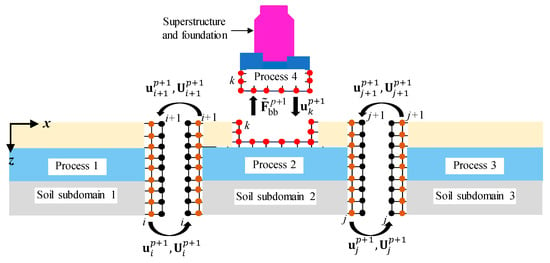
Figure 5.
Schematic diagram of SSI analysis by partitioned algorithms with parallel computation.
The SSI coupling is achieved through data exchange between process 2 and process 4, enabling the use of an inter-field parallel scheme to further improve computational efficiency. In the structural partition, the dynamic response is evaluated using the mode-superposition method, and the time step is determined by the desired accuracy. In contrast, the soil partition adopts an explicit integration scheme, whose time step is restricted by the stability condition and is therefore considerably smaller. Using this smaller step size for both partitions would unnecessarily reduce the structural computation efficiency and increase memory demand. To address this issue, different time steps are adopted for the two partitions: the structural time step is set to be n times the soil time step. The predicted value of is obtained using the soil displacement at time as the external load of the structure at time . The structural response at time is then calculated via the mode-superposition method, after which the resulting displacement and velocity are transferred to the corresponding soil interface nodes. For the interval to , and under the assumption of constant acceleration within each soil time step , the displacement of the soil–structure interface nodes at intermediate soil time levels is estimated using Equation (28):
The implementation process is illustrated in Figure 6. Table 2 provides a concise summary of the workflow for performing the SSI analysis with the parallel computing framework described in this study.
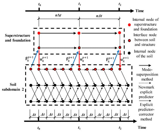
Figure 6.
Computational flow of the asynchronous algorithm for the structure and soil subdomains.

Table 2.
The procedures for partitioned algorithms with parallel computing.
3. Partitioned SSI Analysis for NPP with Pile Foundations Considering Soil Nonlinearity
This section presents the seismic response analysis of a pile-supported CAP1400 NPP located on a soft soil site, where a 40 m-thick clay deposit overlies bedrock. The computational model and associated parameters are outlined below.
3.1. Site and Structure Model
The site is an inland sedimentary formation comprising an overconsolidated clay layer of approximately 40 m in thickness overlying the bedrock. The soil properties adopted in the analysis are listed in Table 3. The upper clay layer is in a hard plastic to semi-stiff state, with a characteristic bearing capacity of 200~300 kPa. The underlying granite bedrock is slightly to moderately weathered, exhibiting a saturated uniaxial compressive strength of 33.96 MPa and a characteristic bearing capacity of 1000~1500 kPa. For the CAP1400 NPP, the design foundation pressures are about 500~600 kPa for the nuclear island and 300~400 kPa for the auxiliary buildings. The foundation embedment depth is 18 m. To satisfy the bearing capacity and settlement requirements, cast-in-place rock-socketed piles are employed. The primary material parameters of the piles are summarized in Table 4.

Table 3.
Material properties of the site soil layers.

Table 4.
Material parameters of C40 concrete piles.
The nuclear island building comprises the shield building, water storage tank, auxiliary building, steel containment vessel, and air inlet. For modeling efficiency, the internal equipment and pipelines are represented using mass and shell elements. Figure 7 illustrates the finite element model of the CAP1400 NPP containment and nuclear island structures. The model consists of 45,810 elements and 35,588 nodes, and the corresponding material parameters are summarized in Table 5.
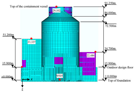
Figure 7.
Finite element model of the CAP1400 nuclear island and containment structures.

Table 5.
Material parameters for the CAP1400 NPP.
The pile foundation design complies with the Code for Design of Nuclear Safety-Related Building Foundations of Nuclear Power Plants (NB/T 20308–2024) [] and the Code for Design of Building Foundations (GB 50007–2011) []. Bored cast-in-place piles with a diameter of 2.2 m and a total length of 24 m are adopted. The pile tips are embedded 2 m into slightly weathered granite, corresponding to an embedment depth-to-diameter ratio of . The comprehensive bearing capacity coefficient at the pile tip is . Neglecting the ultimate side resistance of the surrounding soil, the standard value of the ultimate vertical bearing capacity of a single pile is calculated as
Using the safety factor of , the characteristic vertical bearing capacity of a single pile is obtained as
Within the foundation area of the nuclear island building, 107 piles are arranged with a spacing of m, and the design axial load at the pile head under axial compression is given by
For the auxiliary building, 54 piles are arranged with a spacing of m, and the corresponding design axial load on the pile head is
The design value of the axial compressive strength for C40 concrete is MPa. The axial compressive capacity of the reinforced concrete pile section is calculated as
The verification demonstrates that the designed piles meet the vertical bearing capacity requirements. In total, 161 piles are installed beneath the nuclear island and auxiliary buildings, and their plan layout is shown in Figure 8.
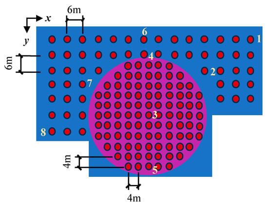
Figure 8.
Plan layout of the pile foundations. The nuclear island and auxiliary building areas are indicated separately, with pile spacing of 4 m and 6 m, respectively.
The SSI model is illustrated in Figure 9. The computational domain extends 450 m × 300 m × 60 m, and transmitting boundaries are applied to represent the radiation of seismic waves into the far field. The soil is discretized using 2 m × 2 m × 2 m hexahedral elements. Piles are represented by equivalent square sections (2 m × 2 m) based on the equal-area approach and are also modeled using solid elements. Following to the partitioned parallel strategy, the entire domain is separated into two primary computational partitions: the soil domain, which is solved with an explicit predictor–corrector scheme, and the superstructure (foundation) partition, which is analyzed using the modal-superposition method. The soil domain is further divided into three subdomains along the x-direction, with one overlapping element layer between adjacent subdomains to ensure numerical continuity. Subdomains 1 and 3 (each 152 m × 300 m × 60 m) are allocated to computational processes 1 and 3, respectively, each containing approximately 334,200 elements and 406,945 nodes. Subdomain 2 (150 m × 300 m × 60 m), where the structure and piles are located, includes about 324,795 elements and up to 399,214 nodes. Both inter-field parallelism and intra-field parallelism are employed to improve computational efficiency.
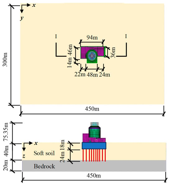
Figure 9.
Site model for SSI analysis of CAP1400 NPP.
3.2. Comparison of Computational Schemes
In the SSI analysis of large-scale NPP models, the total number of DOFs often reaches several hundred thousand or even millions, making an efficient computational strategy essential to achieve sufficient accuracy within a reasonable time. As illustrated in Figure 10, two computational schemes are considered under the assumption of linear elasticity for the pile foundation and superstructure. Scheme (a): The pile foundation and superstructure are treated as an integrated body, and their dynamic response is solved using the modal-superposition method. The surrounding soil domain is modeled separately using an explicit integration scheme, with the soil–structure interaction realized at the interface. Scheme (b): The piles are included within the soil domain, which is solved together using the explicit integration method, while only the superstructure is analyzed via the modal-superposition method. The piles are assumed to remain linear elastic, neglecting material nonlinearity. The modal analysis results for both schemes are presented in Figure 11. Scheme (a) exhibits a larger number of DOFs due to the coupling of piles and superstructure within a single computational domain, resulting in reduced overall stiffness and lower modal frequencies. Consequently, Scheme (a) requires a greater number of participating modes to achieve comparable response accuracy under identical excitation.

Figure 10.
Two computational schemes designed for the SSI analysis of a pile–structure system: (a) the soil is analyzed using the explicit integration method, while the pile–structure system is treated as an integrated body solved by the modal superposition method; (b) both the soil and piles are analyzed explicitly, and the superstructure is solved by the modal superposition method.
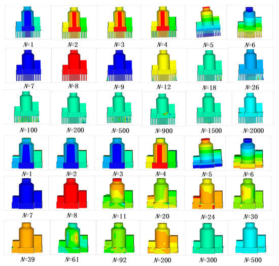
Figure 11.
Comparison of selected mode shapes for the two computational schemes.
The input excitation is applied vertically at the base of the model and, is described by the impulse time function, as shown in Figure 12. A time step of s is adopted, with a total of N = 32,768 calculation steps, resulting in a total duration of 3.2768 s and a corresponding cut-off frequency of 10 Hz.
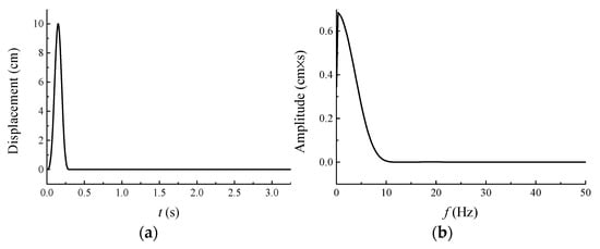
Figure 12.
The SV displacement wave: (a) displacement time history; (b) displacement Fourier amplitude spectrum.
Both schemes adopt an asynchronous partitioned algorithm. The soil partition is solved using explicit time integration with a time step of s, while the structure partition employs modal-superposition method with a time step of s. In Scheme (a), 1000 modes are considered, with a maximum modal frequency of 13.3 Hz; in Scheme (b), 500 modes are included, with a maximum modal frequency of 18.2 Hz. The cumulative effective modal mass in all directions exceeds 90% of the total structural mass, ensuring accurate dynamic response.
Simulations are conducted on a personal computer with an Intel Core i7-14700 processor (28 cores) and 32 GB of memory, using four parallel processes. The soil is modeled as linear elastic, and soil nonlinearity is not considered in this comparison. As shown in Figure 13, the displacement responses of the NPP structure from both schemes are nearly identical, confirming the consistency of dynamic responses. Computational efficiency, however, differs markedly: Scheme (a) requires approximately 293 h, whereas Scheme (b) completes the same analysis in 88 h, achieving nearly a threefold improvement in efficiency.
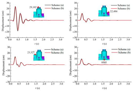
Figure 13.
Comparison of displacement time histories at selected nodes of the NPP structure obtained from the two computational schemes.
Scheme (a) reduces the computational effort required for the soil partition but increases the structural DOFs and lowers the modal frequencies. As a result, more modes must be included, substantially extending the computation time and creating an imbalance in overall efficiency. Scheme (b), by contrast, keeps the modal workload low without sacrificing accuracy, leading to a more balanced and efficient partitioned simulation. Overall, for SSI analysis of pile-supported NPPs using a partitioned parallel algorithm, adopting a scheme that limits the computational demand of the structural partition provides reliable accuracy and significantly improves efficiency—an important advantage for large-scale nonlinear SSI simulations.
3.3. Seismic Response Analysis Considering Soil Nonlinearity
This section employs Scheme (b)—the more computationally efficient strategy in which the piles and soil are solved together using explicit integration, while the superstructure is analyzed via modal-superposition method—to evaluate the seismic response of the CAP1400 NPP.
The seismic input is synthesized to match the RG1.60 standard design spectrum, which is widely recommended in nuclear engineering practice and commonly adopted for engineering verification of NPP seismic performance. Because RG1.60 provides broad and well-defined frequency content representative of design-basis loading, it is appropriate for assessing the dynamic behavior of the system within the scope of this study. After amplitude modulation, the peak ground acceleration is set to 0.2 g and the total duration to 20.48 s. Figure 14 presents the acceleration and displacement time histories together with the corresponding Fourier spectrum of the synthesized wave, and the excitation is applied in the x-direction by prescribing displacement time histories along the soil boundaries. In this analysis, an RG1.60-compatible input is employed to demonstrate the implementation and performance of the proposed computational framework under standard design-basis excitation.
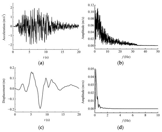
Figure 14.
Input seismic wave in x-direction: (a) Acceleration time history; (b) Fourier amplitude spectrum of acceleration; (c) displacement time history; (d) Fourier amplitude spectrum of displacement.
The soil domain is evaluated using the explicit time integration scheme with a time step of s, while the structural response is obtained through the modal-superposition method with a time step of s. A total of 500 modes are retained to achieve adequate accuracy across the frequency range of interest. Figure 15 shows the relationships between the normalized shear modulus ratio , damping ratio , and shear strain for representative soil and rock materials, which serve as input for the nonlinear soil model.
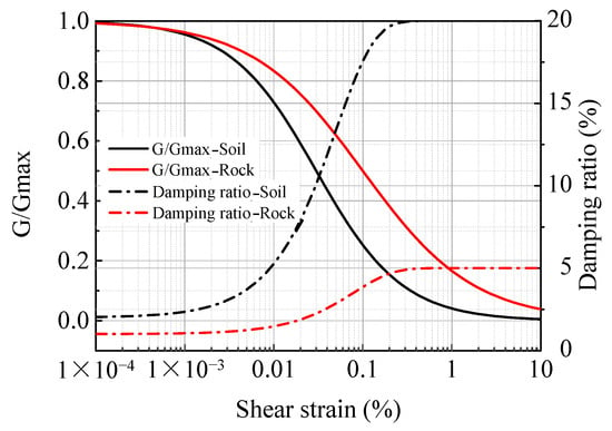
Figure 15.
Typical variation in normalized shear modulus ratio and damping ratio with shear strain for representative soil and rock materials.
Seismic response analyses are performed for two cases: linear soil behavior and nonlinear soil behavior. Figure 16 presents the displacement and acceleration time histories, along with the 5% damped acceleration response spectra at selected observation points of the NPP structure in the x-direction. The results show a clear increase in structural responses with height, reflecting a typical inter-story amplification pattern. Incorporating soil nonlinearity consistently reduces the displacement, acceleration, and spectral peaks at all observation points. In addition, the peak responses occur later in time, and the dominant frequencies of the acceleration response spectra shift toward the lower values. For the containment top node (29,102), nonlinear soil conditions reduce the peak displacement and acceleration by 47.43% and 48.40%, respectively, and the spectral peak by 75.86%. For the auxiliary building top nodes (23,327 and 22,484), peak displacements decrease by 45.80% and 46.09%, and the spectral peaks by 57.32% and 60.75%, while reductions in peak acceleration are more modest at 4.96% and 6.52%. At the foundation top node (9505), the peak displacement decreases by 43.49%, the peak acceleration by 9.16%, and the spectral peak by 57.76%.
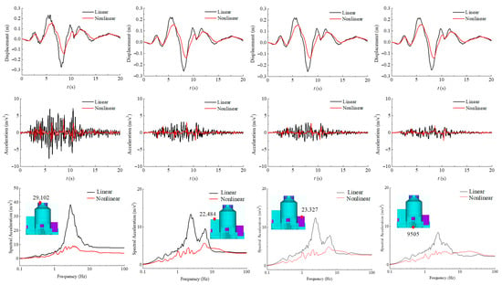
Figure 16.
Comparison of displacement and acceleration time histories and 5% damped acceleration response spectra in the x-direction at representative observation points of the NPP structure.
These results highlight the pronounced influence of soil nonlinearity on the structural seismic response, which is reflected in three main aspects: (1) Reduction in response amplitude, particularly in the upper structural regions, showing that nonlinear soil behavior provides notable attenuation of upward-propagating seismic waves; (2) Dynamic softening of the system, resulting in an increased fundamental period and a delayed occurrence of response peaks; and (3) Shift and attenuation of spectral response, with the dominant frequencies moving toward the low-frequency range and high-frequency components being markedly diminished. Taken together, the findings underscore the necessity of incorporating nonlinear soil behavior in SSI analyses of nuclear power plant structures to achieve more realistic dynamic simulations and improve the reliability of seismic performance evaluations.
To examine the deformation and stress characteristics of the piles under seismic loading, the central, edge, and corner piles beneath the containment and auxiliary buildings (numbered 1–8 as shown in Figure 8) are selected as monitoring points. Figure 17 and Figure 18 present the time-history comparisons of the x-direction displacement, shear force , and bending moment for the corner pile beneath the auxiliary building (Pile 1) and the central pile beneath the containment (Pile 3) at various depths, respectively.
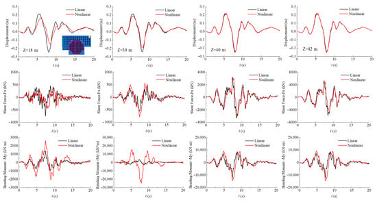
Figure 17.
Time-history comparisons of x-direction displacement, shear force, and bending moment at different depths along Pile 1 (corner pile beneath the auxiliary building).
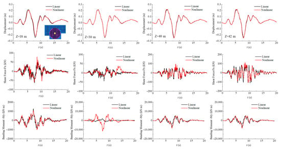
Figure 18.
Time-history comparisons of x-direction displacement, shear force, and bending moment at different depths along Pile 3 (central pile beneath the containment building).
As shown in Figure 17, under nonlinear soil conditions, the x-direction displacement, shear force , and bending moment of the corner pile (Pile 1) beneath the auxiliary building exhibit notable deviations from the linear analysis results. (1) Displacement response: The peak displacement at the pile head decreases by 38.78% compared with the linear case. With increasing depth, the difference between the nonlinear and linear responses gradually diminishes, and their values converge near the pile toe. (2) Shear force response: The peak shear force at the pile head is reduced by 40.50% relative to the linear analysis. Along the pile depth, the peak shear force initially decreases and then increases, reaching its maximum at the pile toe. The discrepancy between nonlinear and linear results gradually reduces with depth, with the nonlinear peak at the pile toe being 16.42% lower than the linear counterpart. (3) Bending moment response: The bending moment distribution follows a different pattern from displacement and shear. Differences between nonlinear and linear results are minor at the pile head and pile toe but become pronounced at mid-depth. At m, the nonlinear peak bending moment is approximately seven times higher than the linear result.
As shown in Figure 18, the central pile (Pile 3) beneath the containment building is less influenced by soil nonlinearity compared with the corner pile (Pile 1). The x-direction displacement along its depth closely matches the linear analysis. Both the shear force and bending moment of Pile 3 are smaller than those of Pile 1. The difference between the nonlinear and linear bending moments is most significant at mid-depth, where the nonlinear peak bending moment at m is approximately 5.5 times greater than the corresponding linear value.
As shown in Figure 19, the distributions of the maximum axial force, shear force, and bending moment along the pile shafts (Piles 1–8) indicate that the pile layout and spacing significantly influence the internal force characteristics of the pile group foundation. Among the piles, the central pile beneath the containment building (Pile 3), with a spacing of 4 m, experiences the lowest axial force, shear force, and bending moment. This is followed by the edge piles beneath the containment building (Piles 4 and 5). In contrast, the corner piles beneath the auxiliary building (Piles 1 and 8), which have a larger spacing of 6 m, exhibit the highest internal forces, followed by the edge piles beneath the auxiliary building (Piles 2, 6, and 7).
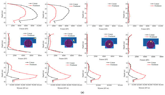
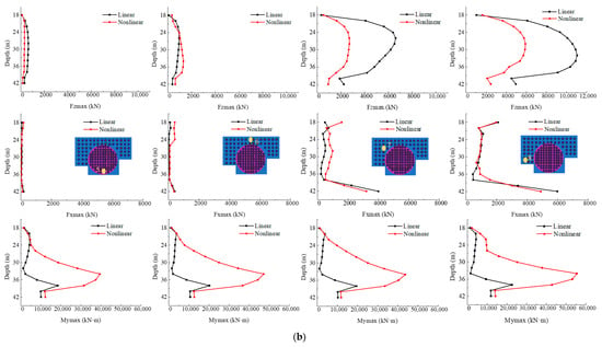
Figure 19.
Distributions of the maximum axial force , shear force , and bending moment along the pile shafts. (a) Piles 1–4; (b) Piles 5–8.
This distribution pattern indicates that, under seismic loading, the piles beneath the containment building—with smaller spacing—experience stronger group-pile interaction and restraint, resulting in relatively lower internal forces. In contrast, the piles beneath the auxiliary building, where spacing is larger, are less constrained by the group effect and thus sustain higher internal forces. Piles located near the structural symmetry axis (Piles 3, 4, 5, and 6) generally carry smaller forces, whereas those beneath the outer auxiliary buildings (Piles 1, 2, 7, and 8) are subjected to larger internal forces, with the corner piles (Piles 1 and 8) being the most critical. At the depth corresponding to the soil–bedrock interface, the axial force, shear force, and bending moment curves exhibit inflection points, reflecting the change in pile loading behavior due to the stiffness transition between soil layers. The maximum bending moment typically occurs slightly above this interface, within the lower–middle section of the pile shaft. It should be noted that the self-weight of the structure was not included in the current calculation, which slightly underestimates the overall axial forces. Additionally, torsional effects of the structure under seismic excitation lead to higher axial forces in the corner and edge piles (Piles 1, 2, 7, and 8) compared with those near the symmetry axis (Piles 3, 4, 5, and 6), due to the combination of bending and torsion.
When soil nonlinearity is considered, the reduction in equivalent stiffness caused by deformation weakens the lateral confinement of the piles, resulting in notable changes in the distributions of axial force, shear force, and bending moment compared with the linear analysis. The main observations are summarized as follows: (1) Axial force: Piles near the structural symmetry axis (Piles 3, 4, 5, and 6) are minimally affected by soil nonlinearity, as their load transfer paths remain stable and their axial forces change only slightly. In contrast, the piles beneath the auxiliary buildings (Piles 1, 2, 7, and 8) exhibit significant reductions in axial force due to the degradation of soil stiffness and weakened lateral restraint. (2) Shear force: The shear response of central piles shows limited sensitivity to soil nonlinearity, whereas the effect is pronounced for the outer and corner piles (e.g., Piles 1 and 8). Soil stiffness degradation modifies the shear transfer path, leading to non-uniform distributions along the pile depth. Although overall peak shear forces decrease compared with the linear results, certain depth intervals exhibit localized amplification. (3) Bending moment: Soil nonlinearity strongly influences the bending moment distribution. Changes at the pile head and toe are minor, while the middle-to-lower sections experience substantial increases in bending moment due to reduced lateral restraint and amplified pile deformation. For example, in Piles 1 and 8, the peak bending moments in the mid-lower segments obtained from the nonlinear analysis are several times greater than those from the linear analysis. These regions represent critical control points for internal force redistribution under seismic loading and should be carefully considered in detailing and reinforcement design.
Table 6 summarizes the maximum axial, shear, and bending stresses along the shafts of Piles 1–8. The results indicate that the center pile beneath the containment (Pile 3) experiences the lowest stress levels, reflecting a relatively light load under seismic excitation. Edge piles beneath the containment and auxiliary buildings (Piles 4–7) exhibit moderate stresses, whereas the corner piles beneath the auxiliary building (Piles 1 and 8) sustain the highest stresses. This stress distribution is consistent with the trends observed in axial force, shear force, and bending moment along the piles, as presented in Figure 19.

Table 6.
Maximum stress values of Piles 1–8 under linear and nonlinear soil conditions.
Table 7 lists the maximum values of the first and third principal stresses (σ1 and σ3) for Piles 1–8. When soil nonlinearity is considered for, the maximum principal stresses of all piles increase relative to the linear case, indicating that nonlinear soil behavior amplifies local stress concentration within the pile shafts and leads to a more critical stress state. Among the different pile locations, the center pile beneath the containment building (Pile 3) exhibits the lowest maximum principal stresses for both σ1 and σ3, followed by the edge piles (Piles 4–7), while the corner piles beneath the auxiliary building (Piles 1 and 8) sustain the highest principal stresses. This pattern aligns with the distributions of axial force, shear force, and bending moment in Figure 19, further confirming the close coupling between the internal force distributions and principal stresses along the pile shafts.

Table 7.
Maximum values of the first and third principal stresses for Piles 1–8.
Figure 20 illustrates the contours of the principal stresses along the pile shafts at the time of maximum σ1 response, revealing the internal stress distribution under nonlinear soil conditions. Compared with the linear analysis, the principal stresses increase notably along the pile shafts, and the high-stress regions expand significantly, exhibiting more complex and concentrated patterns. The highest principal stresses primarily occur in the middle-to-lower sections of the piles, particularly near the upper part of the soil–bedrock interface, where a distinct high-stress band is observed. This region coincides with the bending moment peak shown in Figure 19, indicating that it represents the main zone of pile bending deformation and a critical region for internal stress redistribution under seismic loading. Additionally, under nonlinear soil conditions, the high-stress zones shift slightly upward compared with the linear case, suggesting that stiffness degradation and energy dissipation associated with soil nonlinearity modify the pile–soil interaction mechanism, affecting stress transfer paths and concentration areas.
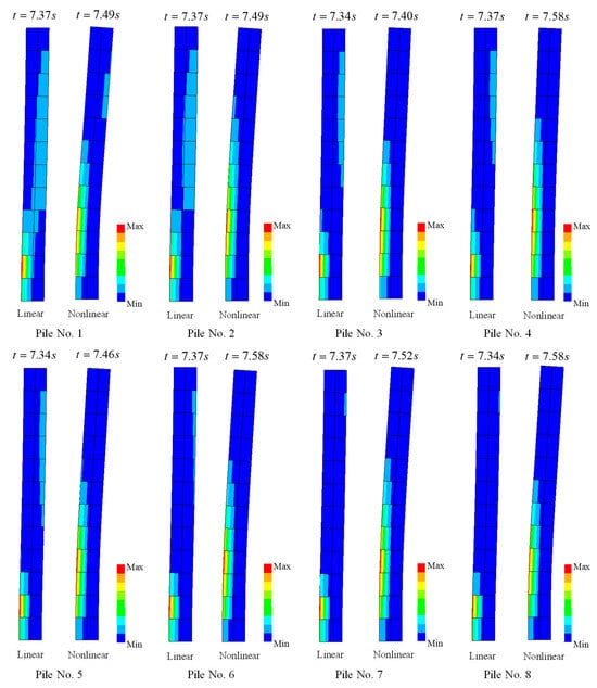
Figure 20.
Distribution contours of the first principal stress along Piles 1–8 under linear and nonlinear soil conditions.
Soil nonlinearity exerts a substantial influence on the seismic response of the structure. It suppresses high-frequency components and reduces overall response amplitude, while simultaneously altering the load transfer characteristics of the piles. Specifically, nonlinear soil behavior modifies shear force paths, increasing bending moments, and intensifies local stress concentrations, thereby raising the potential for damage in critical pile sections. These observations indicate that assuming linear soil behavior may underestimate the seismic demand on the structure. Incorporating soil nonlinearity provides a more realistic representation of pile–soil interaction, enhancing the accuracy of seismic response evaluation and the reliability of safety assessment. Consequently, the nonlinear coupling mechanism between piles and soil should be considered in pile foundation design. Pile layout, length, reinforcement configuration, and stiffness distribution should be optimized based on nonlinear analysis results to ensure deformation compatibility and sufficient energy dissipation under strong seismic events, thereby improving the overall seismic performance and safety of the structure.
4. Conclusions
This study develops a partitioned parallel framework for nonlinear SSI analysis of pile-supported NPP structures. The nonlinear soil behavior is modeled using the Davidenkov backbone curve combined with a modified Masing loading–unloading rule and solved through explicit time integration, while the structural response is computed using the modal-superposition method. The framework is applied to the CAP1400 NPP on a deep soft-soil site, where the piles and superstructure are assumed to remain linearly elastic. Two partitioning schemes are examined: (a) explicit integration for the soil domain with the piles and superstructure treated as an integrated body in the modal solver, and (b) explicit integration for the combined soil–pile domain with only the superstructure analyzed using modal superposition. On the basis of their efficiency in the pulse-loading assessment, the more efficient scheme is adopted for nonlinear seismic response analyses under the RG1.60 design-basis earthquake to investigate the influence of soil nonlinearity on SSI behavior. The main conclusions are summarized as follows:
- The computations are performed on a workstation with an Intel Core i7-14700 processor (16 threads) and 32 GB of memory. The NPP model includes 45,810 elements and 35,588 nodes, and the site model contains 993,195 elements and 1,213,104 nodes, using four MPI processes. Two partitioning schemes are evaluated: Scheme (a) with 1000 structural modes and Scheme (b) with 500 modes. Both schemes produced comparable responses, but Scheme (b) reduced computation time from approximately 293 h to 88 h. The lower efficiency of Scheme (a) is due to the increased structural degrees of freedom from the coupled pile foundation, which reduces overall stiffness and modal frequencies, requiring more modes in the modal superposition analysis. This highlights that selecting a scheme that minimizes the computational cost of the structural partition can significantly improve efficiency without compromising accuracy. The explicit pile–soil coupled approach demonstrates higher computational efficiency and better suitability for large-scale nonlinear SSI analyses.
- Using the efficient explicit pile–soil scheme, dynamic analyses under RG1.60 seismic input show that soil nonlinearity significantly influences the seismic response of the NPP structure, leading to reductions and delays in displacement, acceleration, and spectral peaks, with the dominant frequency shifting toward lower values. Meanwhile, nonlinear effects modify the load transfer mechanism within the pile foundation, causing reconfiguration of the shear force path, amplification of bending moments, and upward expansion of principal stress concentration zones, which may increase the damage potential in locally weak pile regions. From an engineering perspective, these findings highlight the importance of accounting for soil nonlinearity in seismic assessments of pile-supported NPPs. The observed response trends can inform foundation design, structural evaluation, and mitigation strategies, ensuring more reliable predictions of seismic performance. Incorporating such quantitative and physically based interpretations strengthens the scientific impact and practical relevance of the proposed partitioned SSI framework for large-scale nonlinear analyses.
- The proposed computational framework has been partially validated through comparisons with fully explicit nonlinear dynamic analyses on a simplified horizontally layered site, demonstrating its capability to accurately capture nonlinear soil behavior and confirming its reliability for SSI simulations. In the presented NPP case study, the framework proves both feasible and highly efficient for large-scale SSI analyses. While the study focuses on the CAP1400 model, the framework is not restricted to a single plant or scenario. By adjusting the partitioning strategy and selecting suitable computational methods for each subdomain, it can be applied to other NPP models and SSI conditions, including different soil types, deep foundations, or multi-structure interactions. This flexibility enhances its general applicability and supports its use in a wide range of engineering-scale nonlinear SSI analyses.
- The proposed framework demonstrates high computational efficiency and practical applicability for nonlinear SSI analyses of NPP structures. The current study assumes linearly elastic pile behavior and does not account for potential pile–soil slip or separation, which may affect detailed stress distributions. Only a single seismic input (RG1.60) is considered, while comprehensive seismic assessments typically require multiple, more complex ground motions with varying frequency content, duration, and direction to capture variability and ensure robust predictions. Future work will incorporate nonlinear pile behavior, interface effects, three-dimensional interactions, and a broader range of seismic inputs to further enhance the framework’s predictive capability for complex NPP systems. In addition, validation of the proposed method against other computational approaches or experimental results under nonlinear conditions will be conducted to confirm its accuracy and engineering applicability. Detailed sensitivity analyses of soil and structural parameters, which could provide further insight into their influence on SSI responses, are also planned for future research.
Author Contributions
Data curation, L.G.; Formal analysis, L.G.; Methodology, L.G. and S.C.; Supervision, S.C.; Writing—original draft, L.G.; Writing—review and editing, L.G. and S.C. Funding acquisition, S.C. All authors have read and agreed to the published version of the manuscript.
Funding
This research was funded by the National Natural Science Foundation of China, grant number No. U2039209 and the National Key R&D Program Project (2021YFB3302501).
Data Availability Statement
All data, models, or codes that support the findings of this study are available from the corresponding author upon reasonable request.
Conflicts of Interest
The authors declare no conflicts of interest.
Abbreviations
The following abbreviations are used in this manuscript:
| NPP | Nuclear power plant |
| SSI | Soil–structure interaction |
| SPSI | Soil–pile–structure interaction |
| DOFs | Degrees of freedom |
| PASSI | Parallel Analysis of Soil–Structure Interaction |
| MTF | The multi-transmitting formula |
References
- Basu, P.C. Site evaluation for nuclear power plants—The practices. Nucl. Eng. Des. 2019, 352, 110140. [Google Scholar] [CrossRef]
- Xia, F.; Qi, W.; Jing, L.; Wang, Z.; Lu, X. Numerical Simulation of Nuclear Power Plant Pile Foundation Damage Under Earthquake Action. Buildings 2024, 14, 3617. [Google Scholar] [CrossRef]
- Yang, Y.; Fan, H.; Cheng, Y.P.; Gong, W.; Dai, G.; Liang, F.; Jia, Y. Seismic Response of a Nuclear Power Station with a Disconnected Pile–Raft Foundation: Centrifuge Tests and Numerical Study. Soil Dyn. Earthq. Eng. 2022, 160, 107364. [Google Scholar] [CrossRef]
- Yang, Y.; Fan, H.; Cheng, Y.P.; Gong, W.; Dai, G.; Liang, F.; Jia, Y. Seismic response of nuclear power station with disconnected pile-raft foundation using dynamic centrifuge tests. J. Clean. Prod. 2022, 379, 134572. [Google Scholar] [CrossRef]
- Li, Z.; Yang, Y.; Gong, W.; Yi, P.C.; Dai, G.; Liang, F. Investigation on the seismic response of nuclear power stations with a pile-raft foundation using centrifuge tests. Earthq. Eng. Eng. Vib. 2022, 21, 753–768. [Google Scholar] [CrossRef]
- Veletsos, A.S.; Meek, J.W. Dynamic Behaviour of Building–Foundation Systems. Earthq. Eng. Struct. Dyn. 1974, 3, 121–138. [Google Scholar] [CrossRef]
- Gazetas, G. Foundation Vibrations. In Foundation Engineering Handbook; Springer: Boston, MA, USA, 1991; pp. 553–593. [Google Scholar]
- Guin, J.; Banerjee, P.K. Coupled soil-pile-structure interaction analysis under seismic excitation. J. Struct. Eng. 1998, 124, 434–444. [Google Scholar] [CrossRef]
- Ghayoomi, M.; Ghadirianniari, S.; Khosravi, A.; Mirshekari, M. Seismic behavior of pile-supported systems in unsaturated sand. Soil Dyn. Earthq. Eng. 2018, 112, 162–173. [Google Scholar] [CrossRef]
- Zhou, S.-H.; Feng, Z.-J.; Zhang, C.; Zhang, C.-C.; Wang, J.-K.; Wang, S.-Q. Dynamic Response and Damage Analysis of Variable Section Pile Group Foundation at Liquefaction Site Under Different Seismic Intensities. Buildings 2025, 15, 3840. [Google Scholar] [CrossRef]
- Benkhellat, S.; Kadri, M.; Seghir, A. Numerical investigation of the effects of soil-structure and granular material-structure interaction on the seismic response of a flat-bottom reinforced concrete silo. Earthq. Eng. Eng. Vib. 2024, 23, 609–623. [Google Scholar] [CrossRef]
- Roy, S.D.; Pandey, A.; Saha, R. Shake Table Study on Seismic Soil–Pile Foundation–Structure Interaction in Soft Clay. Structures 2021, 29, 1229–1241. [Google Scholar] [CrossRef]
- Sun, Y.; Wang, G.; Wang, Y.; Tu, J.; Jing, L.; Qi, W. Comparative Study on Shaking Table Tests for a Pile–Nuclear Island Structure under Different Soil Conditions. Sustainability 2023, 15, 11988. [Google Scholar] [CrossRef]
- Zhao, H.; Zhang, F. Seismic response of pile-supported structures considering the coupling of inertial and kinematic interactions in different soil sites. Front. Struct. Civ. Eng. 2024, 18, 1350–1361. [Google Scholar] [CrossRef]
- Lysmer, J.; Kuhlemeyer, R.L. Finite Dynamic Model for Infinite Media. J. Eng. Mech. Div. ASCE 1969, 95, 859–877. [Google Scholar] [CrossRef]
- Ostadan, F.; Deng, N. Computer Program: SASSI2010—A System for Analysis of Soil-Structure Interaction, version 1.1; Geotechnical and Hydraulic Engineering Services, Bechtel National Inc.: San Francisco, CA, USA, 2011. [Google Scholar]
- Bolisetti, C.; Whittaker, A.S.; Mason, H.B.; Almufti, I.; Willford, M. Equivalent linear and nonlinear site response analysis for design and risk assessment of safety-related nuclear structures. Nucl. Eng. Des. 2014, 275, 107–121. [Google Scholar] [CrossRef]
- Kabanda, J.; Kwon, O.S.; Kwon, G. Time and frequency domain analyses of the Hualien large-scale seismic test. Nucl. Eng. Des. 2015, 295, 261–275. [Google Scholar] [CrossRef]
- Nguyen, K.T.; Kusanovic, D.S.; Asimaki, D. Three-dimensional nonlinear soil–structure interaction for Rayleigh wave incidence in layered soils. Earthq. Eng. Struct. Dyn. 2022, 51, 2752–2770. [Google Scholar] [CrossRef]
- Coleman, J.L.; Bolisetti, C.; Whittaker, A.S. Time-domain soil-structure interaction analysis of nuclear facilities. Nucl. Eng. Des. 2016, 298, 264–270. [Google Scholar] [CrossRef]
- Prakhya, G.K.V.; Bhattacharya, S. Numerical Models in Geotechnics Including Soil–Structure Interaction. In Modeling in Geotechnical Engineering; Samui, P., Kumari, S., Makarov, V., Kurup, P., Eds.; Academic Press: London, UK, 2021; pp. 429–472. [Google Scholar] [CrossRef]
- Desai, C.S.; Zaman, M. Advanced Geotechnical Engineering: Soil–Structure Interaction Using Computer and Material Models; CRC Press: Boca Raton, FL, USA, 2013. [Google Scholar]
- Çetindemir, O. Nonlinear Constitutive Soil Models for the Soil–Structure Interaction Modeling Issues with Emphasis on Shallow Tunnels: A Review. Arab. J. Sci. Eng. 2023, 48, 12657–12691. [Google Scholar] [CrossRef]
- Hardin, B.O.; Drnevich, V.P. Shear modulus and damping in soils: Design equations and curves. J. Soil Mech. Found. Div. 1972, 98, 667–692. [Google Scholar] [CrossRef]
- Ramberg, W.; Osgood, W.R. Description of Stress–Strain Curves by Three Parameters; National Advisory Committee for Aeronautics (NACA) Technical Note 902; National Advisory Committee for Aeronautics: Washington, DC, USA, 1943. [Google Scholar]
- Dafalias, Y.F.; Popov, E.P. A model of nonlinearly hardening materials for complex loading. Acta Mech. 1975, 21, 173–192. [Google Scholar] [CrossRef]
- Vucetic, M.; Dobry, R. Effect of soil plasticity on cyclic response. J. Geotech. Engineering. 1991, 117, 89–107. [Google Scholar] [CrossRef]
- Kramer, S.L. Geotechnical Earthquake Engineering; Prentice Hall: Upper Saddle River, NJ, USA, 1996. [Google Scholar]
- Pyke, R. Nonlinear soil models for irregular cyclic loadings. J. Geotech. Eng. Div. ASCE 1979, 105, 715–726. [Google Scholar] [CrossRef]
- Bielak, J.; Loukakis, K.; Hisada, Y.; Yoshimura, C. Domain reduction method for three-dimensional earthquake modeling in localized regions: Part I—Theory. Bull. Seismol. Soc. Am. 2003, 93, 817–824. [Google Scholar] [CrossRef]
- Jeremić, B.; Yang, Z.; Lange, D.; Liao, S. Time domain simulation of soil–foundation–structure interaction in non-uniform soils. Earthq. Eng. Struct. Dyn. 2009, 38, 699–718. [Google Scholar] [CrossRef]
- Chen, S.; Wang, J.; Liu, Q.; Zhou, G.; Tang, H. Asynchronous parallel algorithm for three-dimensional soil-structure interaction analysis based on explicit-implicit integration scheme. Sci. Sin. Tech. 2017, 47, 1321–1330. (In Chinese) [Google Scholar]
- Chen, S.; Lv, H.; Zhou, G. Partitioned analysis of soil-structure interaction for Nuclear Island Buildings. Earthq. Eng. Struct. Dyn. 2022, 51, 2220–2247. [Google Scholar] [CrossRef]
- Lv, H.; Chen, S. Analysis of nonlinear soil-structure interaction using partitioned method. Soil Dyn. Earthq. Eng. 2022, 162, 107470. [Google Scholar] [CrossRef]
- Cui, Y.; Hou, T.; Pamukcu, S.; Li, H.; Wang, Y. Dynamic deformation characteristics of lightweight soil based on Davidenkov model. Environ. Geotechnics. 2025, 12, 226–238. [Google Scholar] [CrossRef]
- Jia, P.F.; Yang, A.W. A modified Davidenkov model for stiffness and damping characteristics of saturated clayey soils due to low-amplitude small-strain vibrations. Adv. Mater. Res. 2013, 680, 166–171. [Google Scholar] [CrossRef]
- Zhang, W.; Taciroglu, E. 3D time-domain nonlinear analysis of soil–structure systems subjected to obliquely incident SV waves in layered soil media. Earthq. Eng. Struct. Dyn. 2021, 50, 2156–2173. [Google Scholar] [CrossRef]
- Haskell, N.A. The dispersion of surface waves on multilayered media. In Vincit Veritas: A Portrait of the Life and Work of Norman Abraham Haskell, 1905–1970; American Geophysical Union: Washington, DC, USA, 1990; Volume 30, pp. 86–103. [Google Scholar] [CrossRef]
- Thomson, W.T. Transmission of elastic waves through a stratified soil medium. J. Appl. Phys. 1950, 21, 89–93. [Google Scholar] [CrossRef]
- Xu, L.; Ma, M. Dynamic response of the multilayered half-space medium due to the spatially periodic harmonic moving load. Soil Dyn. Earthq. Eng. 2022, 157, 107246. [Google Scholar] [CrossRef]
- Zhang, J.; Liang, J.; Ba, Z. Equivalent linear analysis of seismic response of horizontally layered fluid-saturated poroelastic half-space. Eng. Mech. 2016, 33, 52–61. (In Chinese) [Google Scholar] [CrossRef]
- Liao, Z.P.; Wong, H.L. A transmitting boundary for the numerical simulation of elastic wave propagation. Int. J. Soil Dyn. Earthq. Eng. 1984, 3, 174–183. [Google Scholar] [CrossRef]
- Martin, P.P.; Seed, H.B. One-dimensional dynamic ground response analyses. J. Geotech. Eng. 1982, 108, 935–952. [Google Scholar] [CrossRef]
- Chen, G.-X.; Zhuang, H.-Y. Developed nonlinear dynamic constitutive relations of soils based on Davidenkov skeleton curve. Chin. J. Geotech. Eng. 2005, 27, 860–864. (In Chinese) [Google Scholar]
- Zhao, D.; Ruan, B.; Chen, G.; Xu, L.; Zhuang, H. Modified irregular unloading–reloading rules and equivalent shear strain algorithm based on the Davidenkov skeleton curve: Model verification. Chin. J. Geotech. Eng. 2017, 39, 888–895. (In Chinese) [Google Scholar]
- Zhao, D.; Ruan, B.; Chen, G. Validation of the modified irregular unloading–reloading rules based on Davidenkov skeleton curve and the implementation in ABAQUS software. In Proceedings of the Seventh China–Japan–US Trilateral Symposium on Lifeline Earthquake Engineering, Shanghai, China, 1–4 June 2016; American Society of Civil Engineers: Reston, VA, USA, 2016; pp. 449–455. [Google Scholar] [CrossRef]
- Chen, G.X.; Liu, X.Z.; Zhu, D.H.; Hu, Q.X. Experimental studies on dynamic shear modulus ratio and damping ratio of recently deposited soils in Nanjing. Chin. J. Geotech. Eng. 2006, 28, 1023–1027. (In Chinese) [Google Scholar]
- Wang, B.H.; Chen, G.X.; Hu, Q.X. Experiment of dynamic shear modulus and damping of Nanjing fine sand. World Earthq. Eng. 2010, 3, 7–15. (In Chinese) [Google Scholar]
- Chen, S.; Liao, Z. Multi-transmitting formula for attenuating waves. Acta Seimol. Sin. 2003, 16, 283–291. [Google Scholar] [CrossRef]
- Belytschko, T.; Mullen, R. Stability of explicit-implicit mesh partitions in time integration. Int. J. Numer. Methods Eng. 1978, 12, 1575–1586. [Google Scholar] [CrossRef]
- Hughes, T.; Liu, W. Implicit-explicit finite elements in transient analysis: Stability theory. J Appl Mech. 1978, 45, 371–374. [Google Scholar] [CrossRef]
- NB/T 20308–2024; Code for Design of Nuclear Safety-Related Building Foundations of Nuclear Power Plants. National Energy Administration: Beijing, China, 2024.
- GB 50007–2011; Code for Design of Building Foundations. Ministry of Housing and Urban–Rural Development of the People’s Republic of China: Beijing, China, 2011.
Disclaimer/Publisher’s Note: The statements, opinions and data contained in all publications are solely those of the individual author(s) and contributor(s) and not of MDPI and/or the editor(s). MDPI and/or the editor(s) disclaim responsibility for any injury to people or property resulting from any ideas, methods, instructions or products referred to in the content. |
© 2025 by the authors. Licensee MDPI, Basel, Switzerland. This article is an open access article distributed under the terms and conditions of the Creative Commons Attribution (CC BY) license (https://creativecommons.org/licenses/by/4.0/).