1. Introduction
Fiber-Reinforced Polymer (FRP) composites are characterized by their high strength, lightweight nature, and corrosion resistance, making them suitable for wide employment for the retrofitting of existing concrete structures and the development of innovative hybrid structures. A key mechanism behind those applications is the confining effect that FRP imposes on the core concrete. Extensive research has demonstrated that externally bonded FRP sheets or FRP tubes provide continuous and substantial passive confinement to the core concrete [
1,
2,
3]. This effectively addresses common limitations of conventional stirrups such as insufficient spacing and susceptibility to corrosion. Additionally, the stress–strain behavior of confined concrete exhibits a marked strain-hardening response, and various constitutive models of FRP-confined concrete have been proposed [
4,
5]. Recently, ultra-high-performance concrete (UHPC) has attracted substantial attention owing to its significant advantages over conventional concrete, including superior mechanical properties and exceptional durability. The introduction of steel fibers enables UHPC to maintain considerable post-cracking tensile strength, exhibiting strain-hardening or strain-softening behavior. However, its failure mode remains predominantly brittle, typically necessitating transverse confinement to enhance the compressive ductility of UHPC members [
6,
7,
8]. In addition, conventional FRP confined concrete columns suffer from excessive FRP material consumption and diminishing marginal returns in the enhancement of core concrete compressive strength.
The FRP–concrete–steel double-skin tubular column (DSTC) conceived and pioneered by Teng et al. [
9,
10] represents a prominent example of hybrid structural members. This structural system comprises an inner steel tube and an outer FRP tube sandwiching the concrete. Crucially, the fibers within the FRP tube are oriented primarily in the hoop direction to provide confinement to the concrete, thereby significantly enhancing its compressive strength and ductility. Furthermore, both the steel and the FRP tubes serve as permanent formwork, streamlining the construction process. Considerable outcomes have demonstrated that DSTCs constitute an effective structural solution, offering high load-bearing capacity, exceptional ductility, and superior long-term durability [
11,
12,
13,
14]. Utilizing UHPC within DSTCs to replace traditional concrete allows the UHPC to be effectively confined while fully exploiting the tensile capacity of the FRP and the compressive strength of the UHPC, thereby improving the structural load-bearing performance [
15,
16]. Wang et al. (2019) studied the compressive performance of DSTCs filled with UHPC [
17]. The test results demonstrated that the adoption of adequate FRP confinement could lead to highly ductile behavior in a DSTC filled with UHPC specimens, while unconfined UHPC exhibited brittle failure under compression. Additionally, Chen et al. (2024) explored the behavior of DSTC-ECC specimens through concentric compression tests [
18]. The DSTC filled with ECC specimens had axial load–axial strain responses that featured a typical bilinear shape, similar to those of the DSTC filled with normal-strength concrete specimens but with better ductility.
Nevertheless, within this composite configuration, the durability of FRP and UHPC is not fully utilized when serving in corrosive environments [
19,
20]. Furthermore, FRP tube confinement exhibits poor high-temperature performance, complicating connections at beam–column joints in prefabricated structures. Alternatively, employing steel tubes or stirrups for confinement introduces durability concerns related to corrosion of the steel components. Moreover, achieving adequate ductility in confined UHPC requires a volumetric stirrup ratio (using an HRB 400 steel bar) exceeding 3% [
21,
22] or a steel ratio (using Q355 steel tube) surpassing 30% [
23,
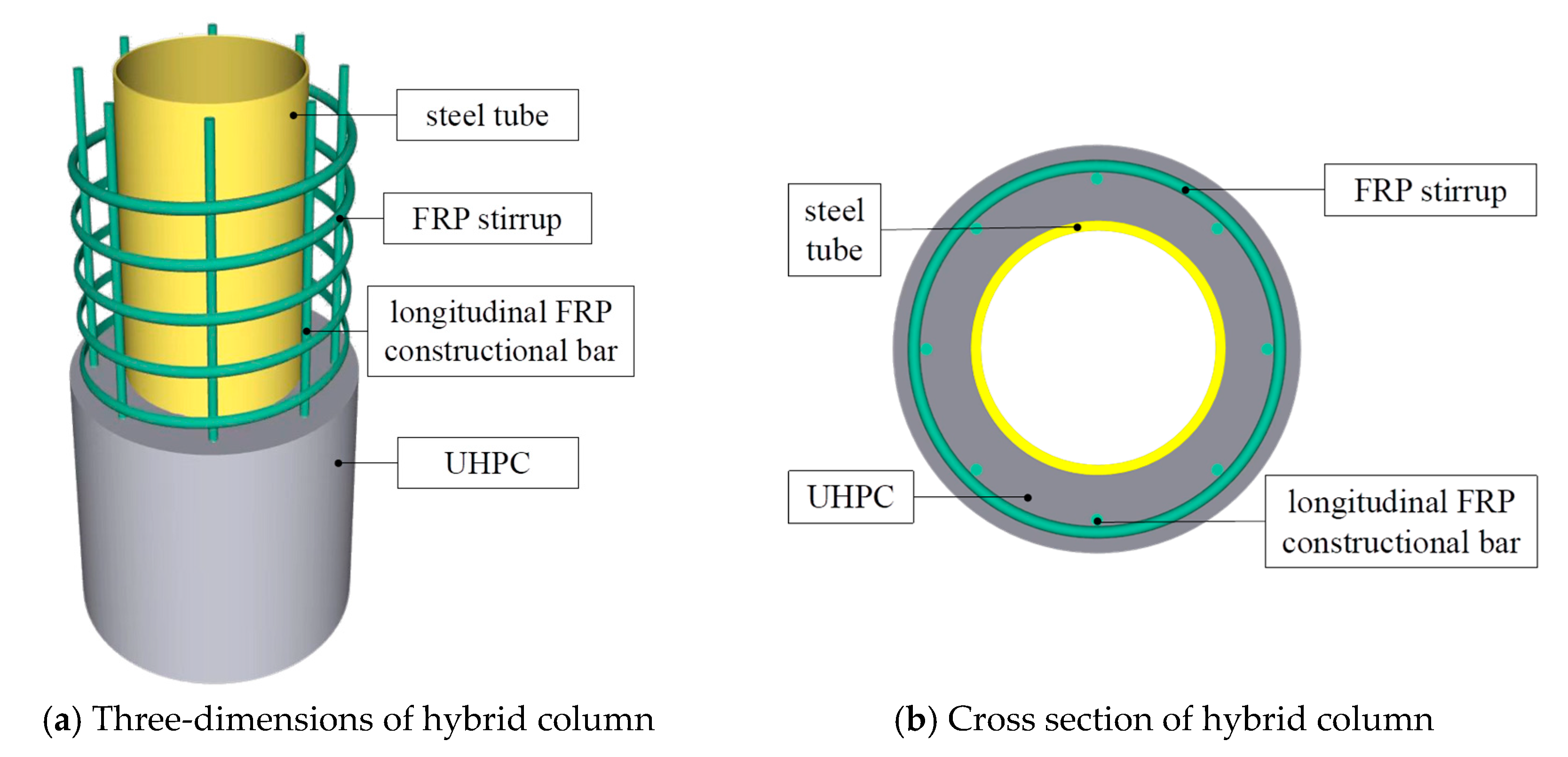
24]. Therefore, this study introduces a novel FRP stirrup-confined UHPC–steel tube (FSCUS) hollow composite column, developed from the double-skin tubular column concept, as illustrated in
Figure 1. The design enhances the outer tube with FRP stirrup-confined UHPC, effectively leveraging the high strength and durability of UHPC, the exceptional confinement and corrosion resistance of FRP, and the ductility of steel tube. To the authors’ knowledge, there is no research on such composite columns. An experimental investigation on the axial compressive performance was carried out to determine the effect of key parameters, clarify the structural mechanism, and reveal the synergistic interactions between the components. The results will provide a theoretical basis for the promotion and application of this composite column.
2. Experimental Program
2.1. Specimen Design
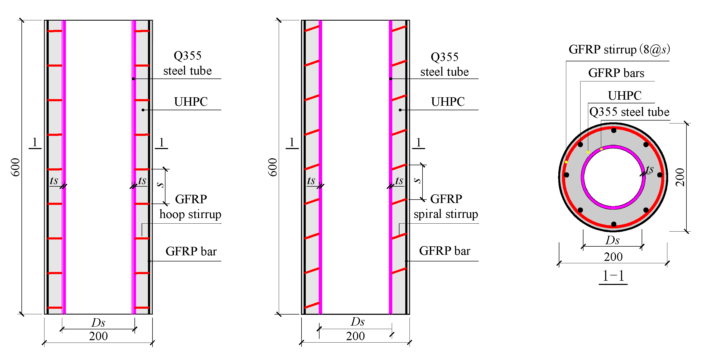
A total of 12 glass fiber-reinforced polymer (GFRP) stirrup-confined UHPC–steel tube (GFSCUS) hollow composite column specimens with identical dimensions were designed and tested under axial compression loads. All column specimens possessed a height of 600 mm and a diameter of 200 mm, and their detailed dimensions are illustrated in
Figure 2. The parameters in total encompass the construction (spiral stirrup or hoop stirrup) and spacing (40 mm, 80 mm or 120 mm) of the GFRP stirrup, outer diameter (42 mm, 76 mm or 114 mm) and thickness (4 mm, 5 mm or 6 mm) of the steel tube, and volume content (0%, 1% or 2%) of the steel fibers. All GFRP bars, including the GFRP longitudinal bar and GFRP spiral and hoop stirrups, possess a diameter of 6 mm. The splicing length of the hoop stirrup is 60 mm. What needs to be explained here is that the advantage of a spiral stirrup over a hoop stirrup lies in its ability to provide continuous and uniform lateral confinement to the core concrete. This mechanism effectively transforms the core concrete from a state of uniaxial compression into a highly efficient triaxial compressive stress state. Consequently, it is typically employed in critical seismic regions and structural members subjected to high axial loads. However, the spiral stirrup has a high cost and a complex production process compared to the hoop stirrup. Both a spiral stirrup and a hoop stirrup were thus designed for the GFSCUS composite column.
The designed parameters of each specimen are presented in
Table 1. The naming convention described in
Table 1 is based on the above-mentioned test parameters. For instance, specimen SS-s80-D76-t4-F2% represents a GFSCUS composite column specimen reinforced with spiral stirrups with a spacing of 80 mm, an outer diameter of the steel tube of 76 mm, a thickness of the steel tube of 4 mm, and incorporating a steel fiber volume content of 2%, respectively. Meanwhile, shear-resistant constructional measurements are configured outside the steel tube to improve the synergistic working between UHPC and steel tube, and can inhibit the internal buckling deformation of steel tube to a certain extent as well. Moreover, both ends of the GFSCUS composite column were strengthened using 3-ply wet-layup CFRP sheets of 30 mm width to avoid premature local stress concentration failure during loading.
2.2. Material Properties
Tensile tests of the GFRP bars (Lianyungang Zhongfu Lianzhong Composites Group Co., Ltd., Lianyungang, China), including GFRP longitudinal bar and GFRP spiral and hoop stirrups, were carried out via three GFRP bar samples with a length of 500 mm and a diameter of 6 mm, the mechanical properties of which are summarized in
Table 2.
The UHPC (Zhejiang Hongri Tenacal New Materials Technology Co., Ltd., Ningbo, China), employed in this study consisted of proprietary premix, steel fibers, and potable water. The matrix mix proportions incorporated silica sand (0.1–0.3 mm) as the fine aggregate and quartz powder (mean particle size ~38 μm, density ~2.65 g/cm
3) as a filler. The mix ratio of cement: silica fume: fine filler: finer aggregate: water: superplasticizer was 1:0.3:0.3:1.34:0.2:0.005. Mixing followed the supplier’s recommended procedures, and all samples and column specimens were cured at ambient temperature for 28 days. During the mixing process, a forced-action mixer was employed to impart sufficient shear forces for disintegrating fiber clusters, while a sufficient mixing duration could be controlled. The compressive strength was determined in accordance with the Chinese standard GB/T 31387-2015 [
25], employing six 100-mm cube samples for testing. The resultant 28-day average compressive strengths for UHPC with 0%, 1.0% and 2.0% steel fiber volume fractions were 96.2 MPa, 112.6 MPa and 128.8 MPa, respectively.
The steel tubes, made of Q355 grade steel, were tested in five dimensions: 76 × 4, 76 × 5, 76 × 6, 114 × 4, and 42 × 4 (where the values denote outer diameter × wall thickness in mm). In accordance with the Chinese standard GB/T 228-2010 [
26], three dog-bone specimens were prepared for each tube thickness for tensile testing.
Table 3 summarizes the material properties of steel tubes with various dimensions.
2.3. Test Setup and Instrumentation
A 20,000 kN electro-hydraulic servo universal testing machine was employed for the experiment. Following the recommendation in Ref. [
27], a displacement-controlled loading protocol was applied to all specimens at a constant rate of 0.5 mm/min. Prior to formal loading, a preloading process was conducted to effectively validate the situations of the two LVDTs, and possible adjustment to the composite column had to be conducted to ensure the force would be uniformly applied. Testing was terminated once the load declined to below 85% of the peak load.
Figure 3 illustrates the test setup and arrangement of strain gauges on the GFRP stirrup, steel tube and UHPC surface. Four axial and four hoop strain gauges were uniformly mounted on the outer UHPC surface. Additionally, four axial and four horizontal strain gauges were attached to the steel tube. All strain gauges were positioned at the mid-height of the specimens. To measure axial deformation, two Linear Variable Displacement Transducers (LVDTs) were installed symmetrically on opposite sides of each column.
3. Results and Discussions
3.1. Failure Mode
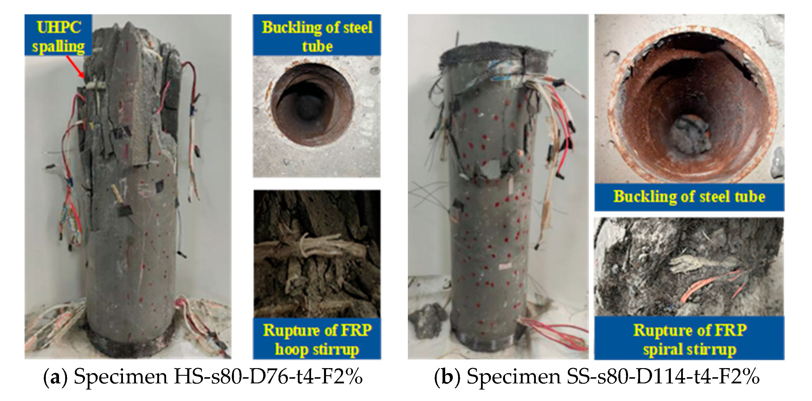
The GFSCUS hollow composite columns initiated with linear elastic behavior, where all components shared the load collectively. As loading increased, microcracks developed in the UHPC layer, while the steel tube yielded near its peak stress. For specimens with spiral FRP stirrups, the continuous confinement effectively restrained concrete expansion, allowing gradual crushing of the UHPC and stable deformation of the steel tube after peak load, leading to a ductile failure mode characterized by bulging in the mid-height region without sudden strength loss. In contrast, columns with circular FRP stirrups experienced brittle failure when discontinuous confinement led to stress concentration at the confined region of the hoop stirrup, causing sudden FRP fracture and explosive spalling of UHPC at the unconfined region accompanied by severe local buckling of the steel tube, as shown in
Figure 4. The final failure mode was thus predominantly governed by the confinement type: spiral stirrups resulted in progressive crushing with maintained integrity, whereas circular stirrups triggered abrupt structural disintegration. Typical failure modes of some specimens are shown in
Figure 4.
3.2. Parametrical Analysis of Load–Displacement Responses
3.2.1. Thickness of Steel Tube
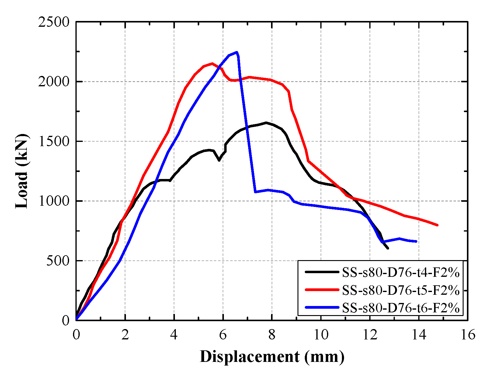
The load–displacement curves of composite columns specimens with different steel tube thicknesses are shown in
Figure 5. The load–displacement curves of composite columns with different steel tube thicknesses are shown in
Figure 5. Specimen SS-s80-D76-t6-2% exhibited approximately 35.73% and 4.47% increases in peak load, respectively, compared to specimens SS-s80-D76-t5-2% and SS-s80-D76-t6-2%. This improvement can be attributed to the increased tube thickness, which enhances both the load-carrying capacity and the axial rigidity of the column. Thicker steel tubes provide stronger confinement and higher inherent strength, thereby more effectively protecting the concrete core under compression and contributing to the overall structural performance.
Moreover, composite columns with thicker steel tubes tend to exhibit a shorter yield stage. This behavior results from the thick steel tube, characterized by its substantial stiffness, which exhibits less transverse expansion compared to the confined UHPC. This differential deformation induces significant interfacial shear stress at the steel–UHPC interface. Excessively high interfacial stress can lead to premature bond-slip or debonding between the steel tube and the UHPC core. Once debonding occurs, the composite action between the steel tube and UHPC is compromised. Consequently, the steel tube can no longer provide effective confinement to the UHPC, while the transverse expansion of the UHPC fails to be fully converted into hoop tension in the steel tube. This loss of synergistic interaction directly results in a significant degradation of the composite columns’ deformability.
3.2.2. Outer Diameter of Steel Tube
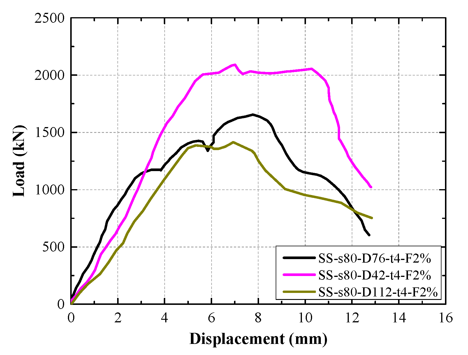
The effect of steel fiber content in UHPC on the load–displacement curves of the GFSCUS hollow composite column is shown in
Figure 6. Specimen SS-s80-D42-t4-2% showed about 47.81% and 26.36% increases in peak load, respectively, compared to specimens SS-s80-D76-t4-2% and SS-s80-D112-t4-2%. This positive improvement of the composite column with a decrease in outer diameter of the steel tube is attributed to the increased cross-sectional areas of both the steel tube and the core concrete, which contribute to higher overall structural resistance.
In addition, as the outer diameter of the steel tube increases, the yield stage of the composite columns becomes shorter. It behaved with the same trend as DSTCs [
28,
29]. This behavior occurs because a larger tube diameter reduces the cross-sectional area of the concrete confined within the stirrups, thereby decreasing the effective composite sectional area. As a result, synergistic interaction between the steel tube and concrete is diminished, leading to a shortened yield stage in the structural response.
Therefore, in the design of such composite columns, an optimal range of thickness and outer diameter of the steel tube exists to ensure the deformation capacity through a well-calibrated synergistic interaction among the steel tube, UHPC, and FRP stirrup. An excessively thick steel tube or steel tube with a relatively large outer diameter compromises this mechanism, shifting the structural failure mode from ductile to brittle and rendering external FRP confinement ineffective.
3.2.3. Spacing and Configuration of GFRP Stirrup
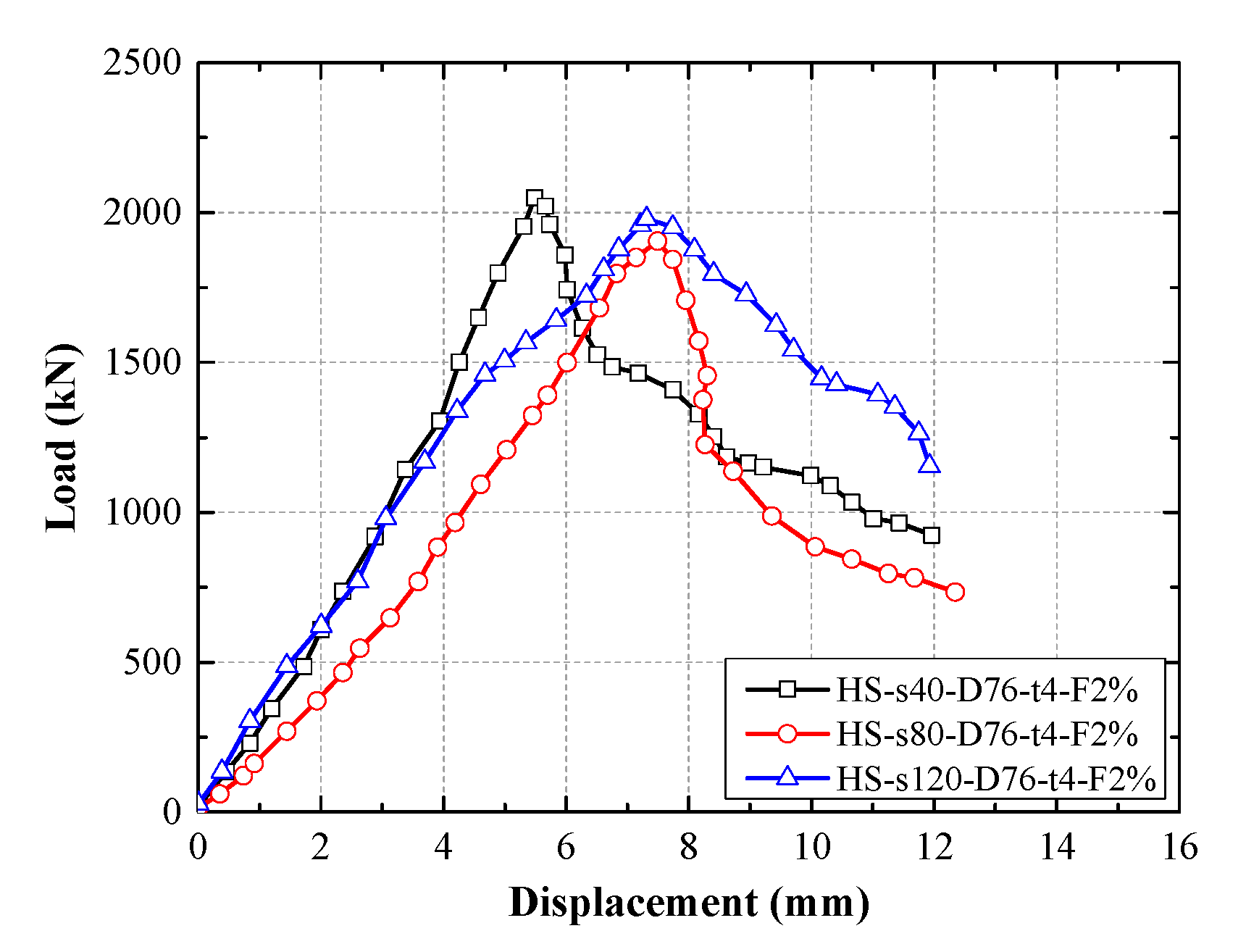
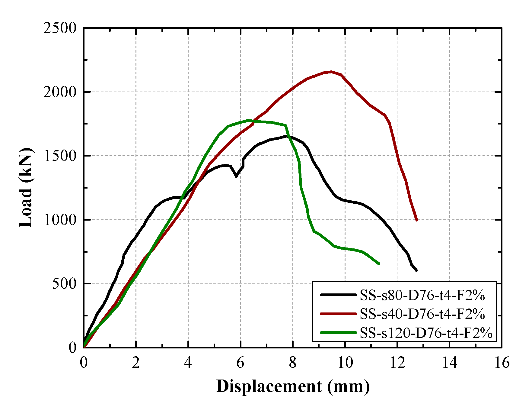
The effect of spacing of the GFRP stirrup on the load–displacement curves of the GFSCUS hollow composite column is shown in
Figure 7 and
Figure 8. It was observed that composite columns with a stirrup spacing of 40 mm exhibited the highest axial compressive strength, regardless of whether spiral or hoop stirrups were used. For specimens with hoop stirrups, the peak load of specimen HS-s40-D76-t4-F2% was 7.56% higher than that of specimen HS-s80-D76-t4-F2% and 3.48% higher than that of specimen HS-s120-D76-t4-F2%. In the case of specimens with spiral stirrups, the peak load of specimen SS-s40-D76-t4-F2% showed an increase of 21.46% compared to specimen SS-s80-D76-t4-F2%, and was 30.35% higher than that of specimen SS-s120-D76-t4-F2%. This improvement can be attributed to the reduced stirrup spacing, which enhances the confinement effect on the core concrete, thereby improving its overall stability and compressive capacity. In contrast, specimens with a stirrup spacing of 120 mm experienced a rapid decline in load-bearing capacity after reaching the peak load. This behavior is due to the larger stirrup spacing, which results in insufficient confinement of the core concrete and poor synergistic interaction between steel tube and concrete, leading to a sharp post-peak strength degradation.
Additionally, comparing
Figure 7 with
Figure 8, it is observed that the shape of load–displacement curves of composite columns configured with a GFRP spiral stirrup was obviously different from that of composite columns confined with a GFRP hoop stirrup. The two-stage load–displacement response and poor ductility observed in composite columns with circular FRP stirrups can be attributed to the discontinuous and non-uniform confinement provided by such reinforcement. Initially, circular stirrups offer limited lateral restraint; however, as axial loading increases, the transverse expansion of the UHPC core induces significant bending moments in the straight segments of the stirrups. Due to the inherent brittleness and low flexural resistance of FRP materials, these regions become susceptible to stress concentration, leading to sudden fracture. Once the stirrups fail, the confinement effect is abruptly lost, resulting in rapid crushing of the concrete core and a sharp post-peak descent in the load–displacement curve.
In contrast, spiral FRP stirrups enhance structural performance by delivering continuous and uniform circumferential confinement to the core concrete. This sustained confinement places the concrete in a more favorable triaxial stress state, not only increasing its ultimate compressive strength but also effectively restraining the propagation of internal microcracks. After the peak load is reached, the spiral reinforcement continues to confine the concrete, controlling its fragmentation and expansion through its capacity for coordinated deformation. This mechanism leads to the emergence of a gradual post-peak softening phase in the load–displacement curve. As a result, the ductility and deformability of the specimen are significantly improved, enabling greater energy dissipation and more stable structural behavior under compression. Meanwhile, for the GFSCUS hollow composite column configured with hoop stirrups, there were multiple occurrences of local yielding of the steel tube, as shown in
Figure 4a. This would result in premature fracture of the FRP stirrups and further crushing of the UHPC.
Furthermore, compared to load–displacement curves of conventional DSTCs [
12,
14], the third stage for the GFSCUS hollow composite column configured with a spiral stirrup exhibited a relatively gentle, not sharp, decline, which is attributed to FRP stirrups providing discrete passive confinement compared to FRP tubes.
3.2.4. Steel Fiber Content
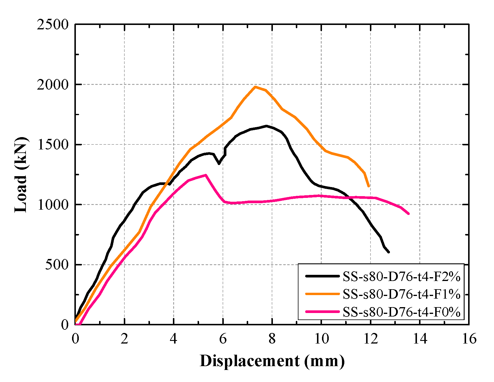
The effect of steel fiber content of UHPC on the load–displacement curves of the GFSCUS hollow composite column is shown in
Figure 9. It is observed that the incorporation of steel fibers into the composite column significantly enhanced its load-bearing capacity. This improvement is attributed to the ability of steel fibers to effectively restrain the development of micro-cracks within the concrete, thereby preventing their propagation into macro-cracks. Uniformly distributed throughout the concrete matrix, the steel fibers bridge across cracks as they initiate, providing additional internal support that resists further crack opening. Notably, the load-bearing capacity of the composite column with 1% steel fiber content was found to be 11.6% higher than that with 2% steel fiber content. This reduction in capacity at higher fiber content is due to excessive fibers restricting the transverse expansion of the core concrete. The confining effect provided by the stirrups is diminished, thereby leading to a decrease in the overall load-bearing capacity of the column. Thus, a steel fiber content of approximately 1% is recommended for the UHPC to achieve an optimal balance between structural performance (including both load-bearing capacity and deformability) and economic efficiency for such composite columns.
3.3. Load–Strain Curves
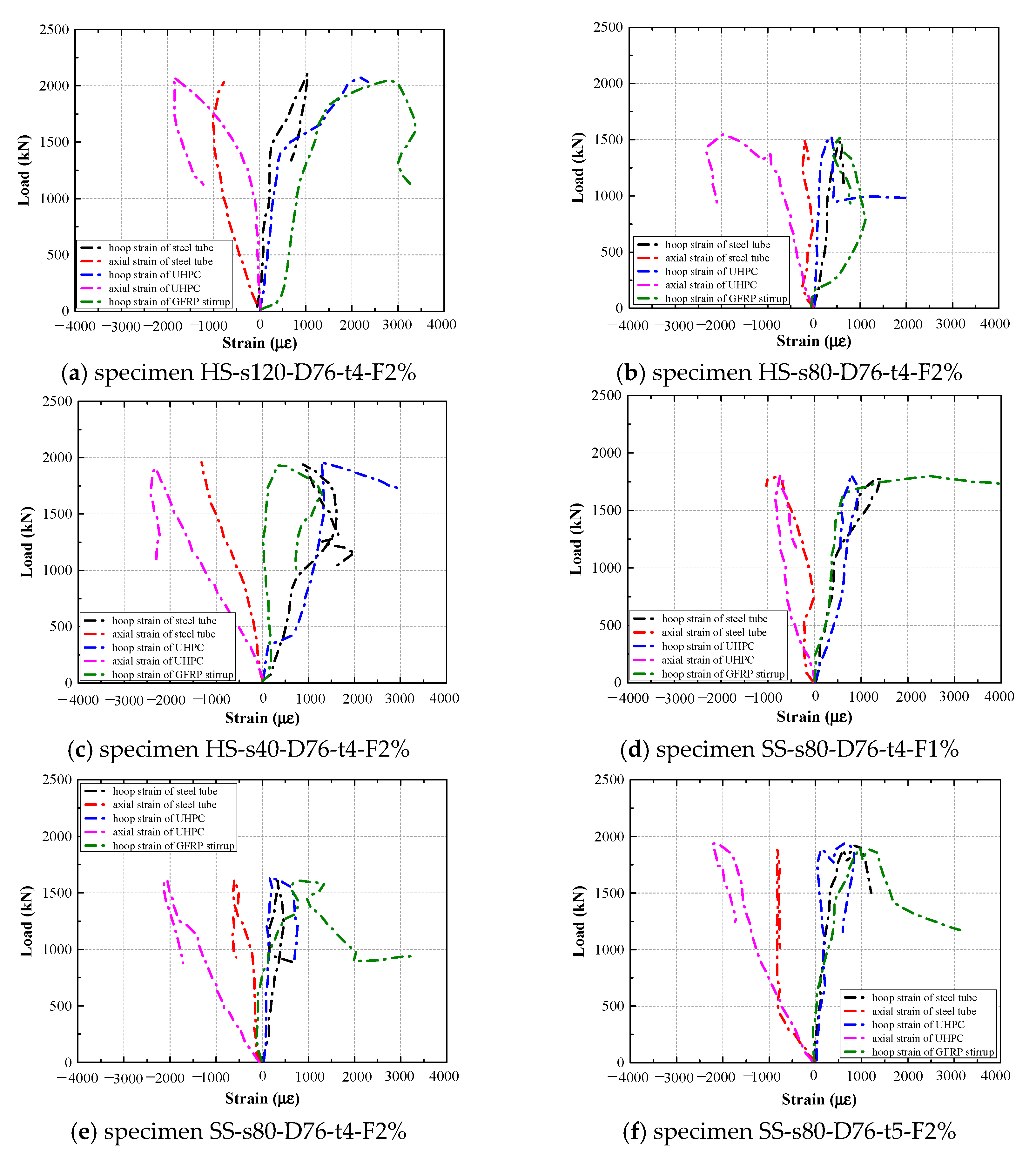
Figure 10 shows the load–strain curves of various components for some specimens. The values are the average values measured by different kinds of strain gauges. Positive values represent the tensile strain; on the contrary, negative values represent the compressive strain.
Generally, in the initial loading stage, the axial strain on the UHPC surface exceeds the hoop strain. This occurs because, under low load levels, the applied force is transmitted primarily along the axial direction of the column. At this point, lateral expansion of the internal concrete remains minimal, leading to a more rapid increase in axial strain compared to the relatively slow development of hoop strain on the UHPC surface. Correspondingly, the slow growth of hoop strain in the stirrups is also attributable to the limited lateral expansion of the core concrete, which results in minimal circumferential deformation of the reinforcement. As for the steel tube, both its axial and hoop strains increase gradually, which can be attributed to its high stiffness.
With a further increase in load, internal microcracks in the concrete progressively develop, and the rate of lateral expansion of the core concrete accelerates. Consequently, the stirrups experience greater tensile hoop strain due to the expanding concrete, and the hoop strain rate on the UHPC surface also rises. Owing to the high stiffness of the steel tube, the growth rates of its axial and hoop strains remain lower than those observed in the stirrups and UHPC. As deformation continues to accumulate within the composite column, the structure eventually becomes unstable and fails.
These things considered, comparing
Figure 10a–c to
Figure 10d–f, it is observed that the hoop strain of the GFRP hoop stirrup developed relatively quicker than that of the GFRP spiral stirrup, demonstrating that hoop stirrups provide confinement early, which might further result in premature rupture of the hoop stirrup as mentioned above.
Additionally, a comparison of the load–strain curves for different stirrup configurations indicates that composite columns with spiral stirrups demonstrate superior synergy in hoop strain development among the various components, in contrast to those configured with hoop stirrups.
3.4. Strain Analysis of UHPC
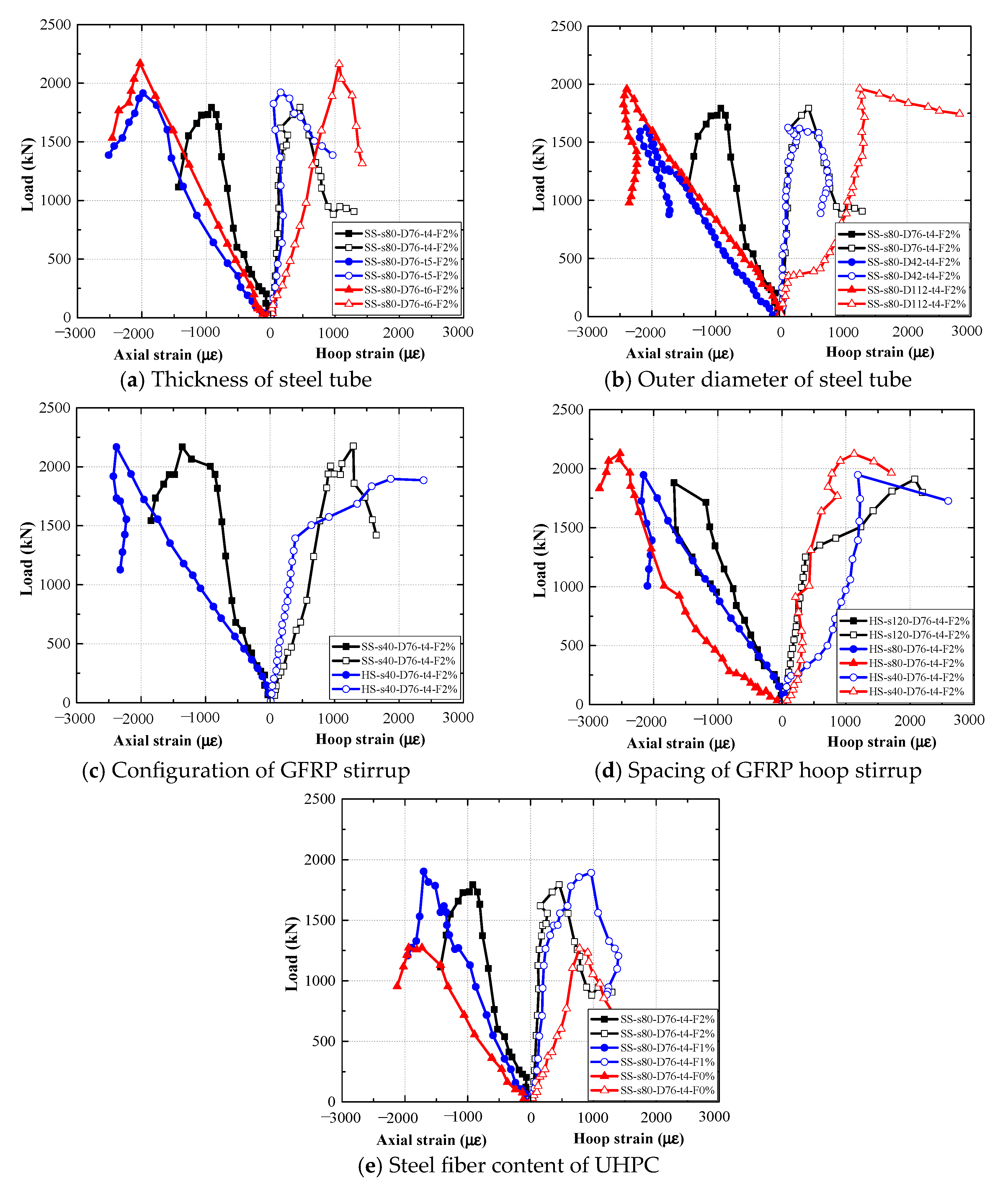
The evolution of axial and hoop strains of UHPC for composite column specimens with various parameters is shown in
Figure 11. As shown in
Figure 11a, as the thickness of the steel tube increases, the axial strain of the composite column decreases. This trend occurs because a thicker tube possesses higher stiffness, leading it to carry a greater share of the axial load. Consequently, the outer concrete experiences reduced stress, resulting in lower axial strain. In the case of the 6-mm-thick steel tube, the UHPC exhibits the highest hoop strain with increasing load. This is attributed to the high stiffness of the thicker tube, which resists deformation and weakens the composite action between the steel tube and the outer concrete. As the two components behave more independently, the concrete is subjected to greater transverse expansion, leading to increased hoop strain.
As shown in
Figure 11b, it can be observed that the composite column with a steel tube diameter of 42 mm exhibited the smallest variation in axial strain as load increased. This behavior can be attributed to its larger cross-sectional area of outer concrete, which distributes stress over a greater area, resulting in minimized axial strain per unit load. In contrast, the specimen with the largest tube diameter of 114 mm showed the most significant increase in hoop strain under loading. Due to the reduced cross-sectional area of the concrete core confined by the stirrups, the effectiveness of the confinement was considerably weakened. As a result, the stirrups were less capable of restraining the lateral expansion of the concrete under axial compression, leading to the most rapid hoop strain development.
As shown in
Figure 11c, compared to hoop stirrups, spiral stirrups provide superior continuity and a stronger confining effect, thereby more effectively restricting concrete deformation. As a result, under identical loading conditions, the outer UHPC layer in columns with spiral stirrups exhibited reduced strain, manifesting as less expansion and smaller axial deformation. For spacing of GFRP stirrups, a smaller stirrup spacing enhanced the confinement effect on the concrete, leading to reduced axial and hoop strains in composite columns subjected to axial compression, as shown in
Figure 11d. In terms of steel fiber content of UHPC, as illustrated in
Figure 11e, the presence of steel fibers effectively suppresses crack propagation and mitigates lateral deformation in composite columns under axial compression, as mentioned above.
4. Calculation of Axial Compressive Load-Bearing Capacity of FSCUS Composite Column
Under the assumption that the FRP stirrup, UHPC, and steel tube work collaboratively, the axial compressive bearing capacity of FSCUS hollow composite column could be divided into two parts: the axial load-bearing capacities of the steel tube and the GFRP stirrup-confined UHPC. The formula can be expressed as Equation (1) based on the superposition principle,
where
is the peak compressive strength of the confined concrete,
is the yielding strength of the steel tube, and
are the cross-sectional areas of UHPC and steel tube, respectively.
In terms of
, numerous models have been developed to predict the ultimate condition of FRP confined concrete, whether it is FRP/steel tube confinement or stirrup confinement, primarily categorized as either design-oriented or analysis-oriented [
28,
29,
30]. Mander’s model is a type of analysis-oriented model [
28], as shown in Equations (2) and (3), which used the iterative analysis method to establish the stress–strain model of confined concrete based on the energy balance. Many subsequent models were optimized and improved on its basis.
where
is the effective lateral confining stress on the core concrete,
,
are the unconfined concrete strength and the axial strain at the unconfined concrete strength, respectively, and
is the axial strain corresponding to
.
Based on Equations (1) and (2), the axial compressive load-bearing capacity of FSCUS composite column could be obtained, as summarized in
Table 4. It was observed that the calculated value was obviously lower than the corresponding values of FSCUS composite columns, particularly specimens SS-s80-D114-t4-F2% and SS-s80-D76-t4-F0%. This is attributed to the following reasons. Firstly, the confinement efficiency of the FRP stirrup was not fully realized in this study. Prior to the UHPC reaching its peak stress, the fiber bridging effect significantly suppressed the development of micro-cracks, resulting in limited lateral dilation of the UHPC. Consequently, the FRP stirrup was not sufficiently strained to mobilize its full confining stress. In addition, compared to a steel stirrup, the FRP stirrup exhibited inferior bond performance with UHPC. Secondly, the composite columns exhibited deficient composite action between FRP stirrup-confined UHPC and the steel tube, manifested by the fact that the confined UHPC failed to attain its peak confined strength once the steel tube yielded or buckled. Additionally, steel tubes with too-large outer diameter and UHPCs without fiber would reduce the cooperative working performance of the composite column, as described in
Section 3.2.
Based on the above reasons, a reduction coefficient
considering the confinement efficiency of the FRP stirrup was introduced, as shown in Equation (4).
Through fitting analysis of the test results of this study, the recommended value of
is 0.723. The modified calculated results are presented in
Table 4 as well. It can be seen that the calculated values considering the reduction coefficient are in good agreement with the experimental values, except for specimens SS-s80-D114-t4-F2% and SS-s80-D76-t4-F0%. However, Equation (3) can only be used to predict the axial compression load-bearing capacity of simpler FSCUS composite columns.
5. Conclusions
This paper presents an experimental study on the axial compression behavior of GFSCUS hollow composite columns. The load–displacement curves obtained from the tests are analyzed, along with the load–strain responses of individual components during the loading process. The effects of various parameters, including thickness and outer diameter of steel tube, configuration and spacing of GFRP stirrups, and steel fiber content of UHPC on the axial compressive performance of GFSCUS hollow composite columns are examined. The following conclusions can be drawn.
(1) The axial compressive behavior of GFSCUS hollow composite columns is governed by the synergy among the steel tube, FRP stirrups, and UHPC. Variations in FRP stirrup configuration mainly led to distinct load–displacement response types. The use of an FRP hoop stirrup could induce brittle failure in such composite columns, whereas an FRP spiral stirrup effectively ensured their ductile behavior.
(2) The influence of steel tube thickness and outer diameter on the axial compression performance of composite columns lies primarily in whether effective composite action can be achieved between the steel tube and FRP stirrup-confined UHPC. Steel tubes with bigger thickness and smaller outer diameter could effectively improve the axial compressive load-bearing capacity and deformation performance of FSCUS composite columns. However, steel tubes with excessively thicker or larger outer diameters might compromise the deformation performance.
(3) Within a fiber content of about 1%, the incorporation of steel fibers enhances both the peak load-bearing capacity and ductility of the composite column due to their bridging effect. However, excessive steel fiber content can restrain the transverse expansion of concrete, thereby reducing the effectiveness of stirrup confinement and leading to a decline in load-bearing capacity.
(4) Owing to the high stiffness of the steel tube, its strain develops at a relatively slow rate under axial compression. Reducing stirrup spacing, adding steel fibers, and modifying stirrup configuration can all effectively restrain concrete deformation. In contrast, excessive steel tube thickness or outer diameter can impair the composite action between concrete and the steel tube, resulting in an accelerated increase in concrete strain.
(5) Based on the superposition principle, considering the confinement efficiency reduction factor of FRP stirrups, a simple and predictable formula for calculating the axial compressive load-bearing capacity of FSCUS composite column is proposed.
Future research on the axial compressive load-bearing capacity calculation method for such composite columns, accounting for parameters such as UHPC fiber content and FRP stirrup reinforcement ratio, is ongoing to facilitate its design application. Furthermore, durability studies, scale-up effects and so forth of such composite columns should be focused on and investigated in the future.
Author Contributions
Conceptualization, J.-B.G. and Y.T.; Validation, F.Y. and Y.T.; Formal analysis, J.-B.G., Z.-Y.X. and F.Y.; Investigation, J.-B.G. and Y.T.; Resources, Y.T.; Writing—original draft, J.-B.G., Z.-Y.X. and F.Y.; Writing—review & editing, J.-B.G., Z.-Y.X. and F.Y.; Visualization, Z.-Y.X.; Supervision, J.-B.G. and Y.T.; Project administration, Y.T.; Funding acquisition, J.-B.G. and Y.T. All authors have read and agreed to the published version of the manuscript.
Funding
This research is supported by grants from the National Natural Science Foundation of Shaanxi Province (Grant No. 2024JC-YBQN-0547); the National Natural Science Foundation of Shaanxi Province (Grant No. 2025SYS-SYSZD-068); the Key Research and Development Program of Shaanxi Province (Grant No. 2024SF-YBXM-636), and the Young Talent Fund of Xi’an Association for Science and Technology (Grant No. 959202413011).
Data Availability Statement
The original contributions presented in the study are included in the article, further inquiries can be directed to the corresponding author.
Conflicts of Interest
The authors declare that they have no known competing financial interests or personal relationships that could have appeared to influence the work reported in this paper.
References
- Lam, L.; Teng, J.G. Design-oriented stress–strain model for FRP-confined concrete. Constr. Build. Mater. 2003, 17, 471–489. [Google Scholar] [CrossRef]
- Elisabetta, M.; Francesca, N.; Giuseppe, V. Basalt-based fiber-reinforced materials and structural applications in civil engineering. Compos. Struct. 2019, 214, 246–263. [Google Scholar]
- Shahawy, M.; Mirmiran, A.; Beitelman, T. Tests and modeling of carbon-wrapped concrete columns. Compos. Part B Eng. 2000, 31, 471–480. [Google Scholar] [CrossRef]
- Montuori, R.; Piluso, V.; Tisi, A. Comparative analysis and critical issues of the main constitutive laws for concrete elements confined with FRP. Compos. Part B Eng. 2012, 43, 3219–3230. [Google Scholar] [CrossRef]
- Montuori, R.; Piluso, V.; Tisi, A. Ultimate behaviour of FRP wrapped sections under axial force and bending: Influence of stress-strain confinement model. Compos. Part B Eng. 2013, 54, 85–96. [Google Scholar] [CrossRef]
- Hung, C.C.; Yen, C.H. Compressive Behavior and Strength Model of Reinforced UHPC Short Columns. J. Build. Eng. 2021, 35, 102103. [Google Scholar] [CrossRef]
- Gu, J.B.; Chen, Y.H.; Tao, Y.; Wang, J.Y.; Zhang, S.X. A Comparative Study on the Flexural Behavior of UHPC Beams Reinforced with NPR and Conventional Steel Rebars. Buildings 2025, 15, 2358. [Google Scholar] [CrossRef]
- Hu, H.L.; Liu, Y.Q.; Xu, X.Q.; Liang, C.; Zhou, Y.W.; Getahun, D. Effect of bond performance on flexural crack width of GFRP bar-UHPC beam: Theoretical model and finite element analysis. Structures 2025, 79, 109604. [Google Scholar] [CrossRef]
- Teng, J.G.; Yu, T.; Wong, Y.L. Behaviour of hybrid FRP concrete-steel double-skin tubular columns. In Proceedings of the International Conference on FRP Composites in Civil Engineering [CICE], Adelaide, Australia, 8–10 December 2004; pp. 811–818. [Google Scholar]
- Teng, J.G.; Yu, T.; Wong, Y.L.; Dong, S.L. Hybrid FRP-concrete-steel tubular columns: Concept and behavior. Constr. Build. Mater. 2007, 21, 846–854. [Google Scholar] [CrossRef]
- Han, L.H.; Tao, Z.; Liao, F.Y.; Xu, Y. Tests on cyclic performance of FRP-concrete-steel double-skin tubular columns. Thin-Walled Struct. 2010, 48, 430–439. [Google Scholar] [CrossRef]
- Zhou, Y.W.; Liu, X.M.; Xing, F.; Li, D.W.; Wang, Y.C.; Sui, L.L. Behavior and modeling of FRP-concrete-steel double-skin tubular columns made of full lightweight aggregate concrete. Constr. Build. Mater. 2017, 139, 52–63. [Google Scholar] [CrossRef]
- Peng, K.D.; Yu, T.; Hadi, M.N.S.; Huang, L. Compressive behavior of hybrid double-skin tubular columns with a rib-stiffened steel inner tube. Compos. Struct. 2018, 204, 634–644. [Google Scholar] [CrossRef]
- Bai, Y.L.; Zhang, Y.F.; Jia, J.F.; Han, Q.; Gao, W.Y. Compressive behavior of double-skin tubular stub columns with recycled aggregate concrete and a PET FRP jacket. Constr. Build. Mater. 2022, 332, 127321. [Google Scholar] [CrossRef]
- Wang, J.; Wang, Z.; Yu, T.; Nie, X.F.; Zhang, S.S. Behavior of FRP-UHPC-steel double-skin tubular columns under eccentric compression. J. Build. Eng. 2025, 108, 112884. [Google Scholar] [CrossRef]
- Wang, H.X.; Liu, Y.; Ouyang, C.Y.; Tang, H.Y.; Bian, Y.; Tao, Q.; Yao, B. Axial compression behavior of stainless steel tube-UHPC-carbon steel tube stub column. J. Constr. Steel Res. 2025, 227, 109340. [Google Scholar] [CrossRef]
- Wang, W.; Wu, C.; Liu, Z. Compressive behavior of hybrid double-skin tubular columns with ultra-high performance fiber-reinforced concrete (UHPFRC). Eng. Struct. 2019, 180, 419–441. [Google Scholar] [CrossRef]
- Chen, G.M.; Guo, Y.Z.; Lin, G.; Xiong, Y. Compressive Behavior of FRP-UHPC/ECC-Steel Double-Skin Tubular Columns under Eccentric Loading. J. Compos. Constr. 2024, 28, 04023020. [Google Scholar] [CrossRef]
- Tang, J.P.; Feng, R.; Quach, W.M.; Zeng, J.J. Axial compressive behaviour of simulated corrosion-damaged RC columns retrofitted with UHPFRC jackets subjected to dry-wet cycling condition. Constr. Build. Mater. 2024, 424, 135956. [Google Scholar] [CrossRef]
- Tang, J.P.; Feng, R.; Quach, W.M.; Zeng, J.J. Evaluation of flexural performance on corrosion-damaged RC beams retrofitted with UHPFRCC under marine exposure. Eng. Struct. 2025, 333, 120193. [Google Scholar] [CrossRef]
- Shehab, H.; Eisa, A.; Wahba, A.M.; Sabol, P.; Katunsky, D. Strengthening of Reinforced Concrete Columns Using Ultra-High Performance Fiber-Reinforced Concrete Jacket. Buildings 2023, 13, 2036. [Google Scholar] [CrossRef]
- Huang, L.; Su, L.W.; Xie, J.H.; Lu, Z.Y.; Li, P.J.; Hu, R.L.; Yang, S. Dynamic splitting behaviour of ultra-high-performance concrete confined with carbon-fibre-reinforced polymer. Compos. Struct. 2022, 284, 115155. [Google Scholar] [CrossRef]
- Hoang, A.L.; Fehling, E.; Lai, B.; Thai, D.K.; Van Chau, N. Experimental study on structural performance of UHPC and UHPFRC columns confined with steel tube. Eng. Struct. 2019, 187, 457–477. [Google Scholar] [CrossRef]
- Wei, J.G.; Xie, Z.T.; Zhang, W.; Luo, X.; Yang, Y.; Chen, B.C. Experimental study on circular steel tube-confined reinforced UHPC columns under axial loading. Eng. Struct. 2021, 230, 111599. [Google Scholar] [CrossRef]
- GB/T 31387–2015; Reactive Powder Concrete. China Architecture & Building Press: Beijing, China, 2015. (In Chinese)
- GB/T 228.1–2010; Metallic Materials–Tensile Testing–Part 1: Method of Test at Room Temperature. China Architecture & Building Press: Beijing, China, 2010. (In Chinese)
- Chen, G.M.; Lan, Z.H.; Xiong, M.X.; Xu, Z. Compressive Behavior of FRP-confined Steel-reinforced High Strength Concrete Columns. Eng. Struct. 2020, 220, 110990. [Google Scholar] [CrossRef]
- Mander, J.B.; Priestley, M.J.N.; Park, R. Theoretical stress-strain model for confined concrete. J. Struct. Eng. 1988, 114, 1804–1826. [Google Scholar] [CrossRef]
- Lam, L.; Teng, J.G. Ultimate condition of fiber reinforced polymer-confined concrete. J. Compos. Constr. 2004, 8, 539–548. [Google Scholar] [CrossRef]
- Toutanji, H.A. Stress-strain characteristics of concrete columns externally confined with advanced fiber-composite sheets. ACI Mater. J. 1999, 96, 397–404. [Google Scholar]
| Disclaimer/Publisher’s Note: The statements, opinions and data contained in all publications are solely those of the individual author(s) and contributor(s) and not of MDPI and/or the editor(s). MDPI and/or the editor(s) disclaim responsibility for any injury to people or property resulting from any ideas, methods, instructions or products referred to in the content. |
© 2025 by the authors. Licensee MDPI, Basel, Switzerland. This article is an open access article distributed under the terms and conditions of the Creative Commons Attribution (CC BY) license (https://creativecommons.org/licenses/by/4.0/).
