1. Introduction
With the rapid development of urban underground space and municipal infrastructure construction, the pipe-jacking method has been widely adopted in municipal engineering projects such as water supply and drainage, gas, power, and utility tunnels, owing to its remarkable advantages of minimal construction disturbance, limited environmental impact, and strong adaptability to different ground conditions [
1,
2,
3,
4,
5,
6]. However, with the increasing number of pipe-jacking projects, problems encountered during construction have gradually become apparent. In practice, the complex ground conditions that pipe jacking must traverse often lead to differential ground settlement, which can easily cause offsets between adjacent pipes. In addition, uneven distribution of jacking forces and limitations in construction accuracy can also contribute to this issue [
7,
8,
9]. Typically, bell and spigot joints are used between pipes. These joints primarily provide structural connection and watertightness, but their stiffness is significantly lower than that of the pipe body. When shear displacement caused by offset occurs, this can further result in leakage and a reduction in the overall structural performance, thus posing risks to both the safety and durability of the project [
10,
11,
12,
13]. In recent years, structural resilience has emerged as an important measure of underground structures’ ability to maintain functionality under disturbance. The investigation of joint behavior under offset conditions contributes to improving the resilience and service reliability of jacking pipe systems [
14,
15].
Extensive research has been conducted worldwide on the mechanical behavior of pipe-jacking structures during jacking operations. Zhong [
16] employed full-scale tests combined with numerical simulations to investigate the stress response of concrete and reinforcement in JPCCP pipes under axial jacking forces. Gong [
17] used numerical simulations to analyze the stress distribution of PCCP pipes under different jacking forces and geological conditions, and concluded that axial eccentric forces can significantly increase local stresses and induce structural damage. Zhao [
18] analyzed the variation and influencing factors of circumferential contact pressure in layered strata with soft-over-hard soil conditions using field monitoring data. Zhang [
19] monitored the contact pressure and pipe stress in a curved pipe-jacking project at Gongbei, and reported that axial pipe stress is primarily governed by the jacking force, whereas circumferential stress is controlled by earth and grouting pressures. Moreover, compressive stress concentrations occur at the intrados of the curve, where the stress magnitude reaches its maximum, and there is a strong interaction between circumferential and axial stresses in steel pipes. Li [
20] conducted field monitoring on a long-distance rock pipe-jacking project in Chongqing and found that internal voids caused by manufacturing defects transformed compressive stress into localized tensile stress during jacking, leading to concrete cracking.
Research on the mechanical behavior of bell and spigot joints has also attracted significant attention. Xu [
21,
22,
23,
24] performed laboratory tests and numerical simulations to study the shear failure mechanism of F-type bell and spigot joints in rectangular pipes. The results indicated that joint failure under shear offset was centro-symmetric, and the shear force–displacement curve of the joint could be divided into three stages: initial contact, steel ring warping, and weld cracking. Increasing the steel ring width and thickness effectively improved the shear capacity of the joint. Wu [
25] developed a refined three-dimensional finite element model of PCCP pipes and used a fluid–structure interaction approach to analyze the mechanical response of joints under differential foundation settlement. The results indicate that when a vertical relative displacement occurs between pipes, concrete damage first initiates at the crown–haunch transition zone and subsequently propagates laterally from the crown toward both sides. Becerril García [
26] conducted full-scale experiments to examine the effect of surface load magnitude and position on joint deformation. Liu [
27] combined full-scale tests with numerical simulation to investigate the stress distribution of pipes under deflection and found that the deflection angle significantly increased the tensile stress in the joint region. Tong [
28] established a refined pipe-jacking model and studied the joint failure modes under different eccentric loading patterns and angles. The results indicated that under eccentric loads, stress concentration at the pipe contact surface was pronounced, leading to localized joint cracking or crushing, followed by crack propagation toward the mid-span region of the pipe.
2. Overview of the Project
The Wuhan Road pipe-jacking project is located in the western section of Wuhan Road, Tianfu New District, Chengdu. The total length of the pipe-jacking alignment is 2.94 km, extending from west to east. The designed jacking starting point is at the pipeline section along Jiannan Avenue, and the endpoint is at the reserved interface near Yizhou Avenue. The alignment primarily passes through moderately weathered sandstone strata, with a relatively deep burial depth ranging from 10 to 20 m. The project employs six main jacks for pipe jacking, with a maximum jacking force of up to 12,000 kN, as illustrated in
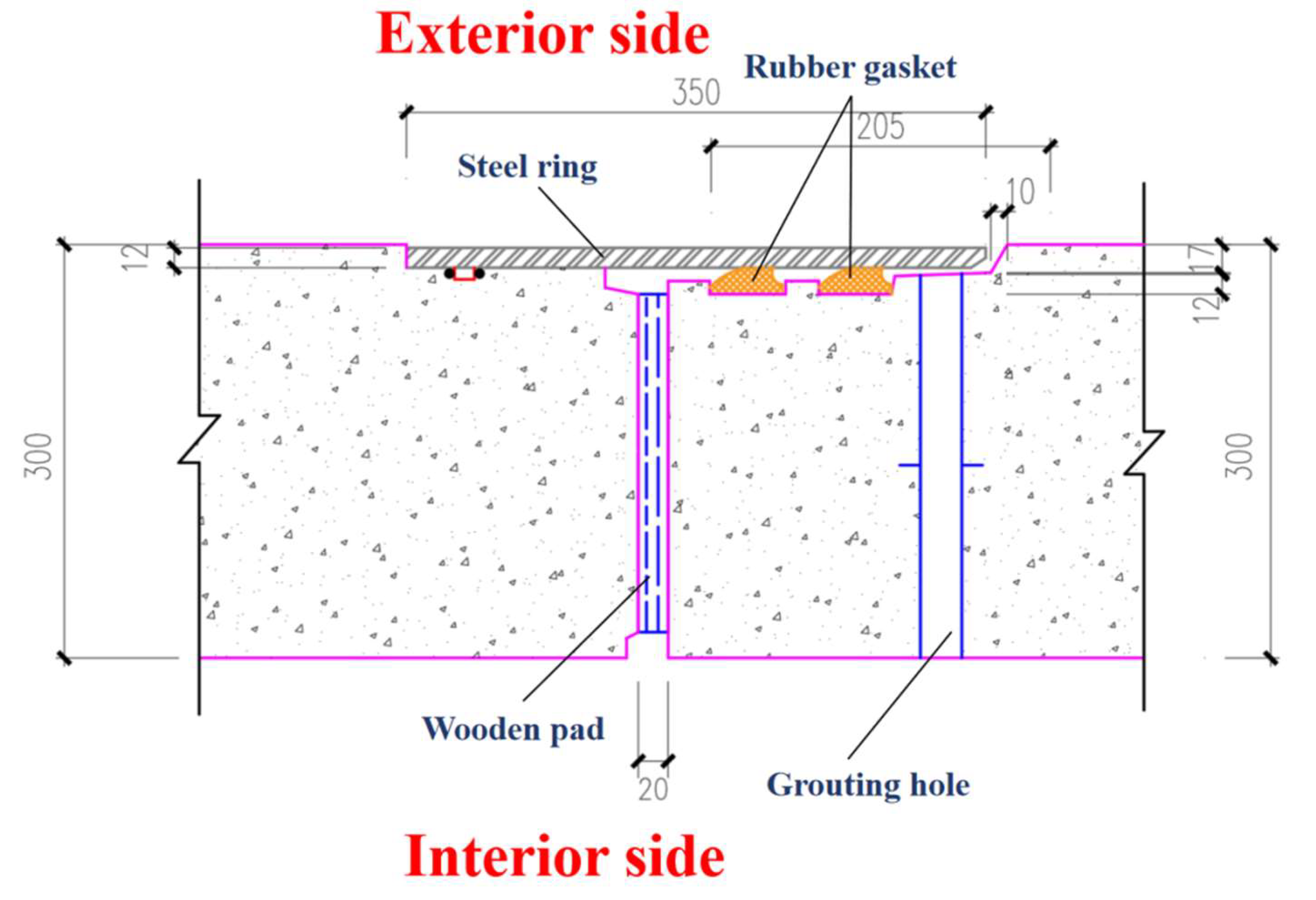
Figure 1. The jacked pipes are made of reinforced concrete, with each pipe measuring 2.5 m in length, 3 m in internal diameter, and 0.3 m in wall thickness. Bell and spigot joints are used for pipe connections, and the detailed joint configuration is shown in
Figure 2.
3. Numerical Model
3.1. Establishment of Numerical Model
To investigate the mechanical behavior of bell and spigot joints under different offsets and jacking force levels during pipe-jacking operations, a three-dimensional numerical model of the pipe was developed using the finite element software ABAQUS 2020. The joint region was modeled in detail to capture its local stress response. Since this study focuses on the joint behavior during the jacking process, and the contact force generated by the compression of the rubber gasket has only a minor influence on the joint stress [
29], the rubber gasket was not modeled [
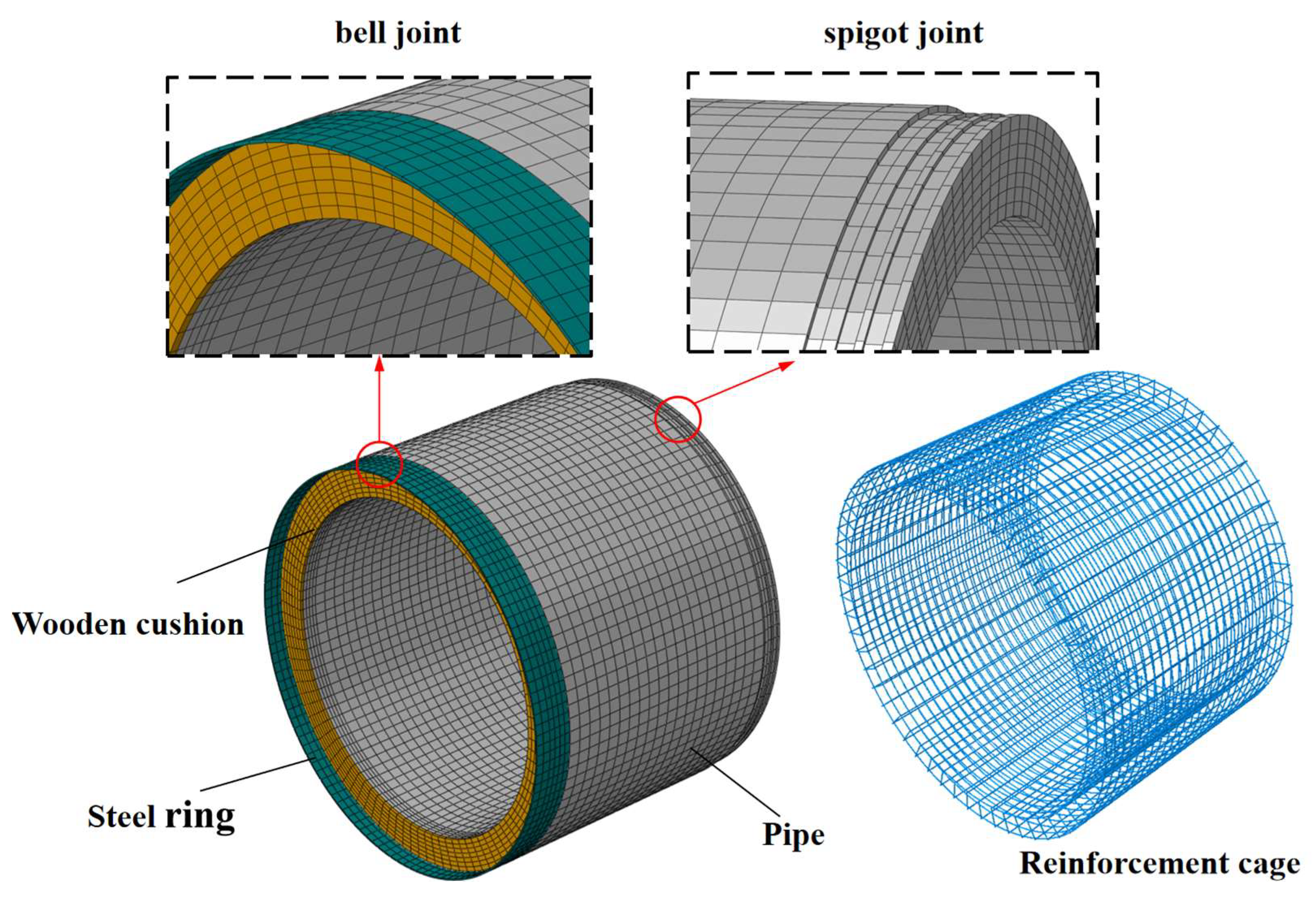
30]. The geometry and mesh layout of the pipe model are illustrated in
Figure 3.
In this numerical analysis, the concrete strength of the pipe body is C50, and the Concrete Damaged Plasticity (CDP) model provided by ABAQUS was used to simulate the nonlinear behavior of the concrete.
Table 1 presents the CDP parameters used in the current simulation. The wooden cushion was modeled using an isotropic linear elastic constitutive model, while both the steel collar and the reinforcement cage were represented by a bilinear elastic–plastic model. For the finite element mesh, the concrete, steel ring, and wooden cushion were simulated using eight-node linear brick elements with reduced integration (C3D8R), and the reinforcement cage was simulated using two-node linear three-dimensional truss elements (T3D2). The material mechanical parameters used in the calculation are presented in
Table 2. The element size of the pipe was approximately 110 mm, whereas the bell and spigot joint region, which is the focus of this study, was locally refined with an element size of about 40–50 mm [
31]. The entire numerical model consisted of 100,356 elements in total.
3.2. Boundary Conditions and Calculation Methods
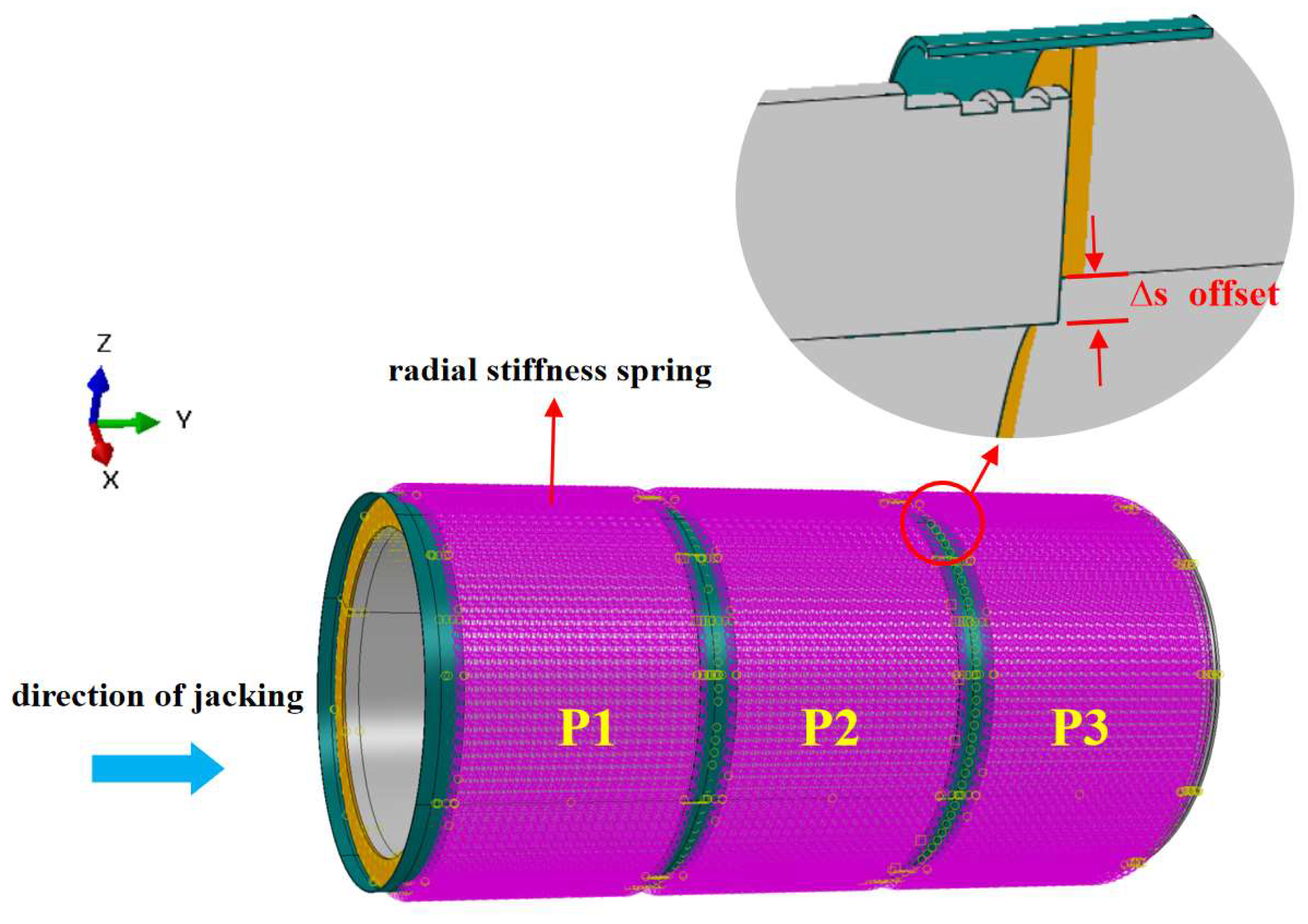
Three identical pipes were modeled in series, as shown in
Figure 4. In this model, the steel ring and wood cushion were tied to the bell end using Tie constraints. The reinforcement cage was embedded within the pipe body, while surface-to-surface contact was defined between the spigot end and the wood cushion as well as the steel ring. The normal contact behavior was defined as hard contact, and tangential behavior was modeled using a penalty function with a friction coefficient of 0.2 [
32,
33,
34]. The confining effect of the surrounding rock on the pipe was simulated by applying foundation springs along the exterior surface of the pipe body. The spring elements were defined as compression-only, with a uniform stiffness of 976 kN/m maintained both in the longitudinal and circumferential directions of the pipe. Furthermore, to realistically represent the frictional resistance between the surrounding rock and the pipe during the pipe-jacking process, the influence of the slurry lubrication layer was incorporated. Based on the parameters provided in the engineering design documentation, a frictional stress of 7 kPa was applied to the exterior surface of the pipe to simulate the interaction friction between the surrounding rock and the pipe.
To simulate the jacking process under offset conditions, the analysis was conducted in two steps: (1) The displacement of the spigot end of pipe P3 was fixed. The jacking force was assumed to be uniformly distributed and converted into an equivalent uniformly distributed circular load applied to the bell end of pipe P1. (2) Keeping the jacking force constant, a downward displacement (negative Z-direction) was applied to pipe P2 to simulate the occurrence of offset between adjacent pipes.
4. Results and Discussion
4.1. Effect of Offset on the Stress Characteristics of Joints
According to the Specification for Construction and Acceptance of Water Supply and Drainage Pipeline Projects (GB 50268-2008) [
35], the joint offset during pipe-jacking construction should not exceed 20 mm. To investigate the effect of offset on the mechanical behavior of bell and spigot joints during jacking operations, the jacking force was kept constant at 4000 kN, and seven working conditions were considered with joint offsets of 0 mm, 5 mm, 10 mm, 15 mm, 20 mm, 25 mm, and 30 mm. The bell and spigot joint of pipe P2 was selected as the subject for stress analysis.
4.1.1. Analysis of Stress in the Concrete at Joints
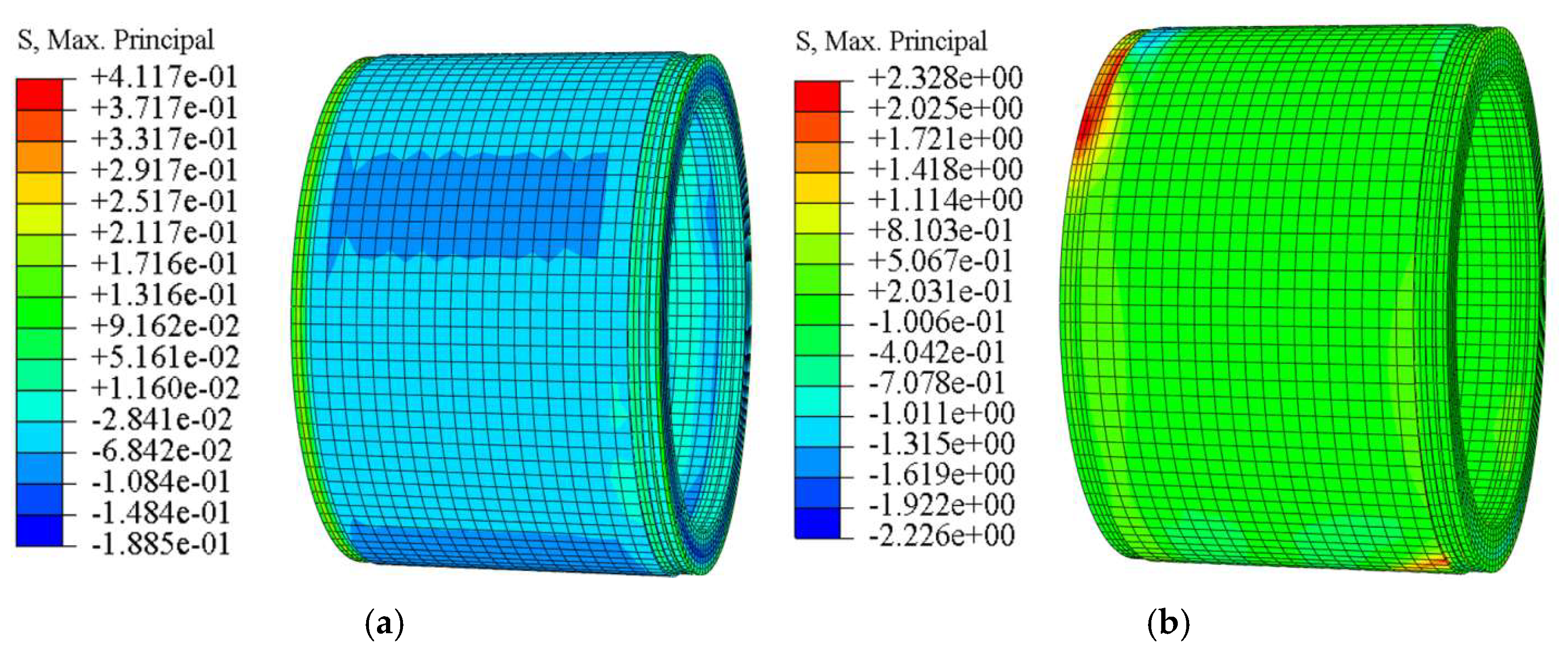
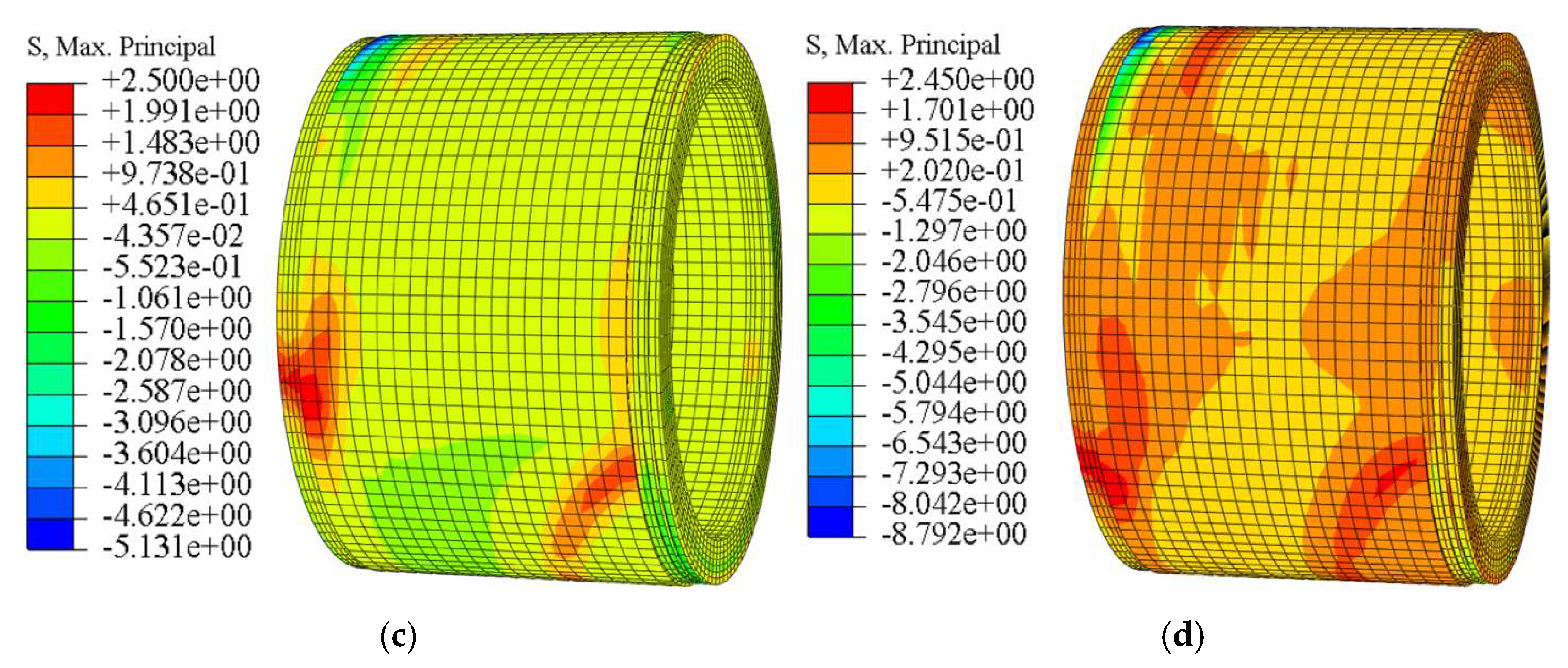
Figure 5 shows the contours of the maximum principal stress in the pipe concrete under different offset magnitudes. As illustrated, when no offset is present (0 mm), the stress in the pipe is uniformly distributed, and the entire pipe remains in compression under the axial jacking force. A small region of tensile stress appears on the outer side of the bell end, but the magnitude is relatively low, with a maximum tensile stress of only 0.41 MPa. When the offset increases to 10 mm, the steel ring at the crown of the bell end comes into close contact with and begins to press against the concrete of the spigot end of the preceding pipe (P1). Simultaneously, the concrete at the invert of the spigot end comes into contact with and is compressed by the steel ring of the following pipe (P3). At this stage, the tensile stress on the outer sides of both the bell and spigot ends becomes significantly greater than in other regions, and the tensile stress in the joint concrete increases sharply compared with the case of zero offset, reaching a maximum value of 2.33 MPa. As the offset further increases to 20 mm and 30 mm, the shear-compression interaction between the steel rings and the concrete at the bell crown and spigot invert intensifies, and the contact area between adjacent pipe ends gradually decreases. Pronounced diagonal tensile stress concentrations appear along the pipe, with maximum tensile stresses of 2.50 MPa and 2.45 MPa, respectively—still below the tensile strength of C50 concrete.
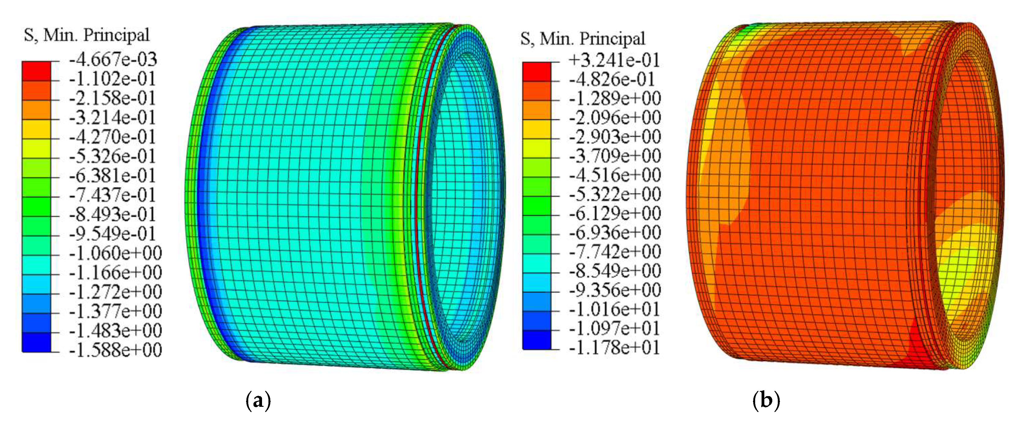
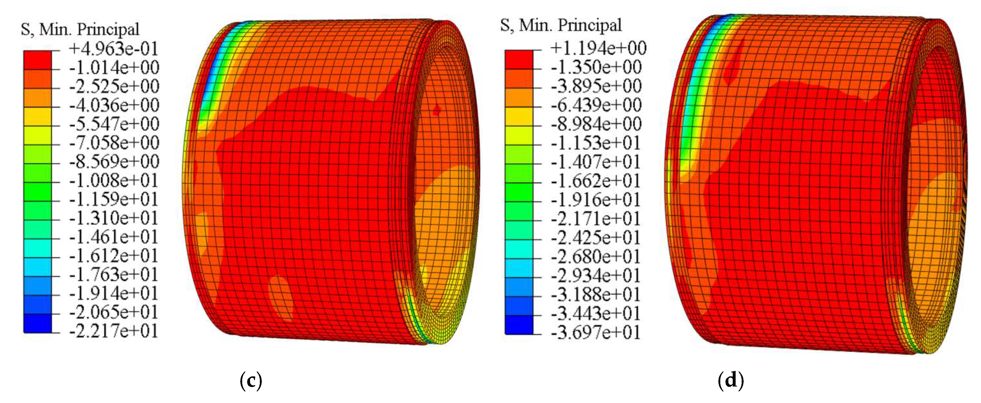
Figure 6 shows the contours of the minimum principal stress in the pipe concrete under different offset magnitudes. As illustrated, when no offset is present, the pipe end is subjected to the axial jacking force transmitted from the preceding pipe, resulting in a uniformly distributed compressive stress. However, the overall magnitude is relatively low, with a maximum compressive stress of only 1.59 MPa. When the joint offset increased to 10 mm, the steel ring at the bell end constrained the spigot of the preceding pipe. Under the action of vertical offset, the steel ring underwent warping deformation, producing radial compression on the concrete at the crown of the bell end. Consequently, the compressive stress in this region exhibited a rapid increase, reaching a maximum value of 11.78 MPa, which is approximately eight times greater than that under the non-offset condition. As the offset further increased to 20 mm, pronounced compressive stress concentrations developed at the crown of the bell end and the invert of the spigot, with the joint compressive stress continuing to rise rapidly. The maximum compressive stress at this stage reached 22.17 MPa. When the offset was further increased to 30 mm, the maximum compressive stress at the crown of the bell end reached 36.97 MPa, which significantly exceeds the compressive strength of C50 concrete (33.5 MPa).
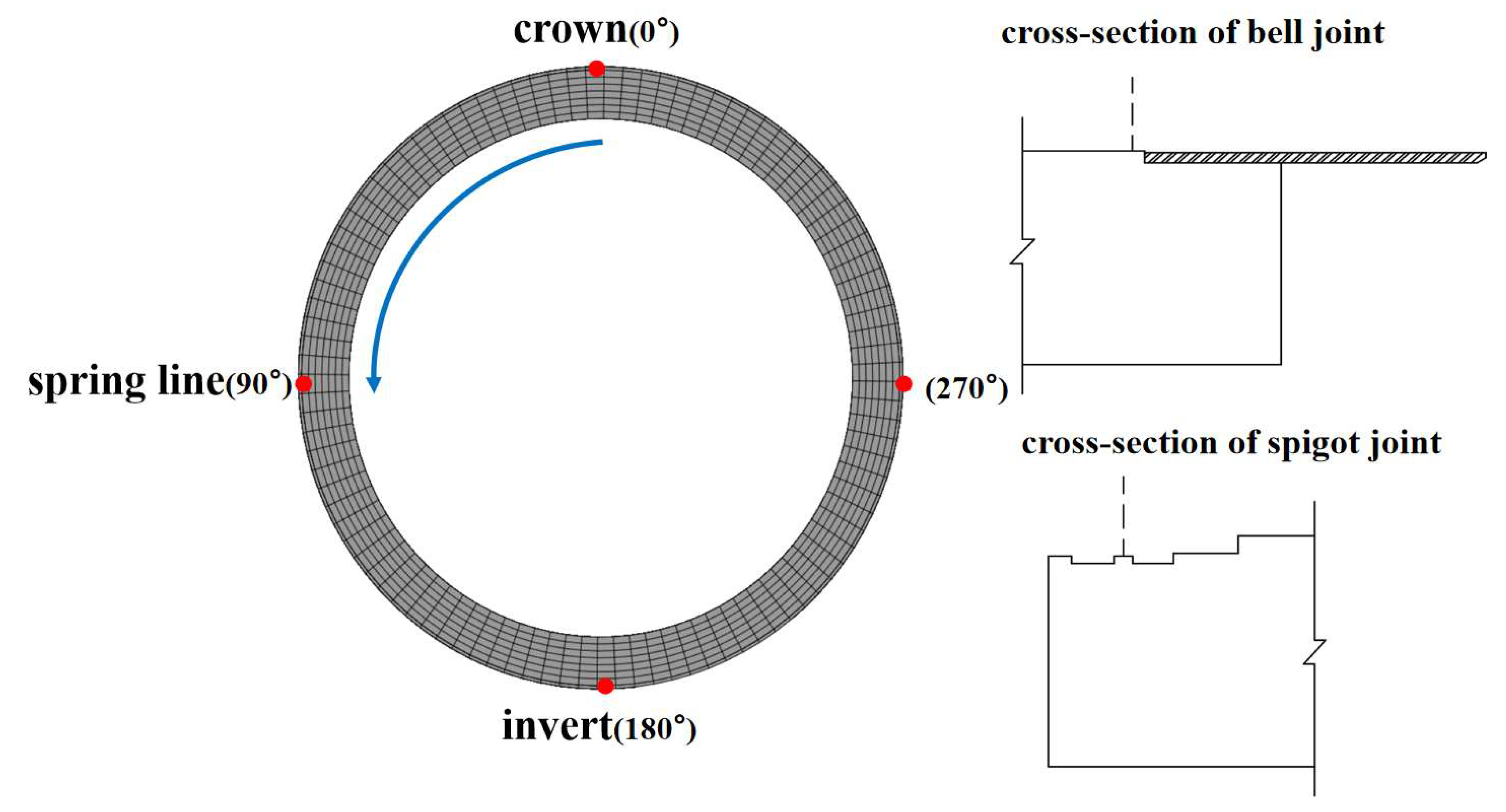
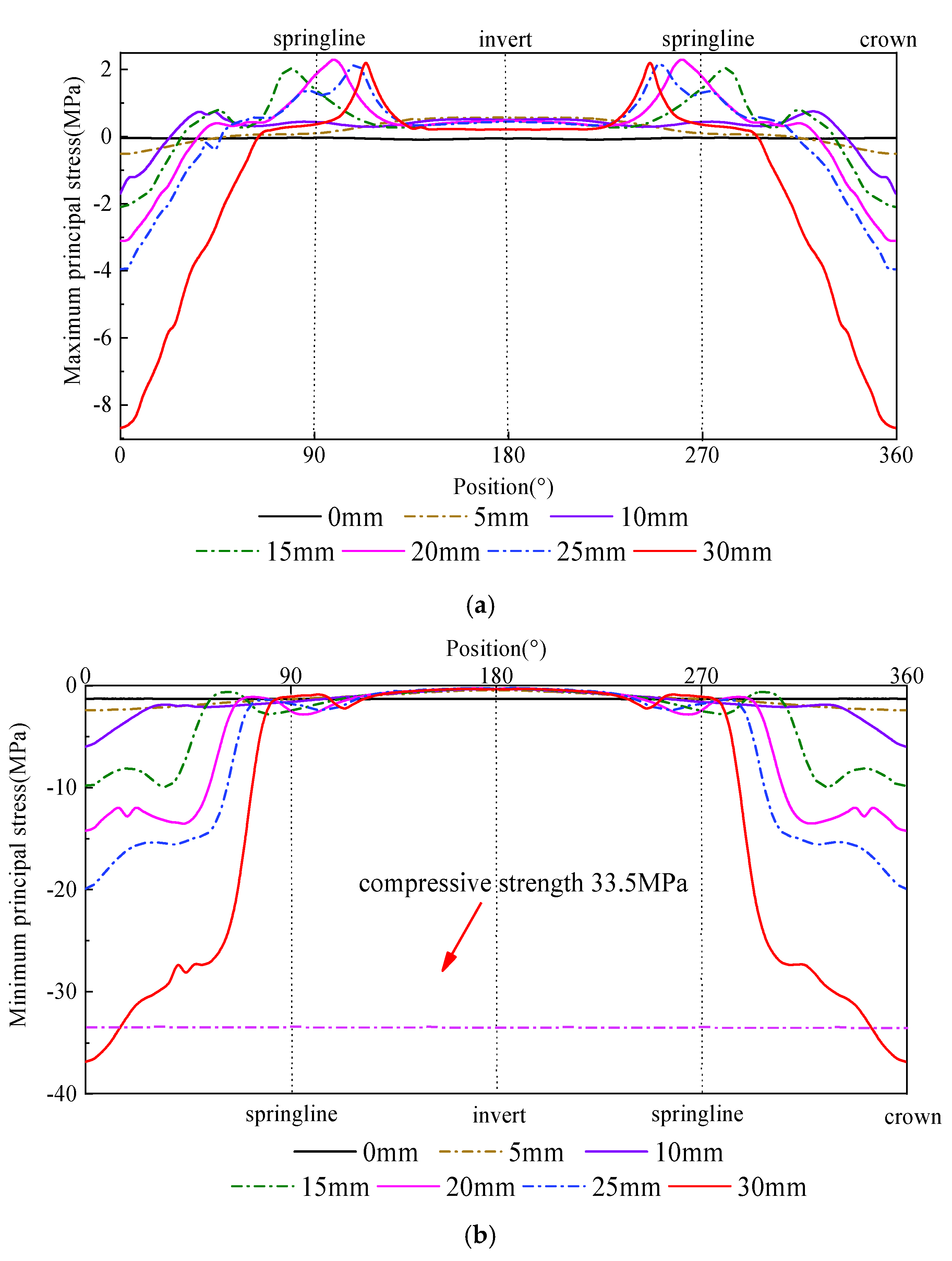
To investigate the stress distribution along the joint cross-section when an offset occurs between pipes, one representative cross-section was selected at both the bell end and the spigot end. The maximum and minimum principal stresses of the concrete were extracted circumferentially along each cross-section. The crown and invert correspond to angular positions of 0° and 180°, while the left and right springline correspond to 90° and 270°, respectively. The specific extraction path and cross-section locations are shown in
Figure 7.
Figure 8a presents the distribution of the maximum principal stress in the concrete at the bell-end cross-section. As shown in the figure, when a vertical offset occurs between pipes, the maximum principal stress in the bell concrete is symmetrically distributed along the cross-section centerline. When the offset does not exceed 10 mm, the overall tensile stress in the bell cross-section remains low, with the highest tensile stress occurring at the invert, reaching only 0.73 MPa. When the offset increases to 15 mm, the tensile stress in the bell cross-section rises sharply, and the maximum tensile stress shifts to the haunch, reaching 2.00 MPa. As the offset further increases to 30 mm, under the effect of diagonal eccentric loading, the location of the maximum tensile stress moves from the haunch toward the springline, while the growth rate of tensile stress becomes relatively small. The maximum value reaches 2.18 MPa, representing an increase of 9.0% compared with the 15 mm offset case.
Figure 8b shows the distribution of the minimum principal stress in the concrete at the bell-end cross-section. It can be observed that the distribution pattern of the minimum principal stress remains generally similar under different offsets, with the stress symmetrically distributed along the cross-section centerline: compressive stress is greater at the crown and smaller at the invert. As the offset gradually increases, the maximum compressive stress in the bell concrete exhibits a parabolic growth trend. This is because the continuous increase in offset causes warping deformation of the steel ring at the crown, leading to a progressive rise in the compressive stress in the concrete near the contact area between the bell and the steel ring. When no offset is present (0 mm), the maximum compressive stress in the bell concrete is only 1.34 MPa. When the offset increases to 10 mm, the growth of compressive stress is still relatively small, reaching 6.02 MPa. However, with further increase in offset, the maximum compressive stress grows exponentially. At an offset of 25 mm, the maximum compressive stress reaches 19.98 MPa, approximately 15 times that of the case with no offset. When the offset reaches 30 mm, the maximum compressive stress rises to 36.93 MPa, which significantly exceeds the compressive strength of the concrete, indicating that compressive failure has occurred in the crown concrete of the bell.
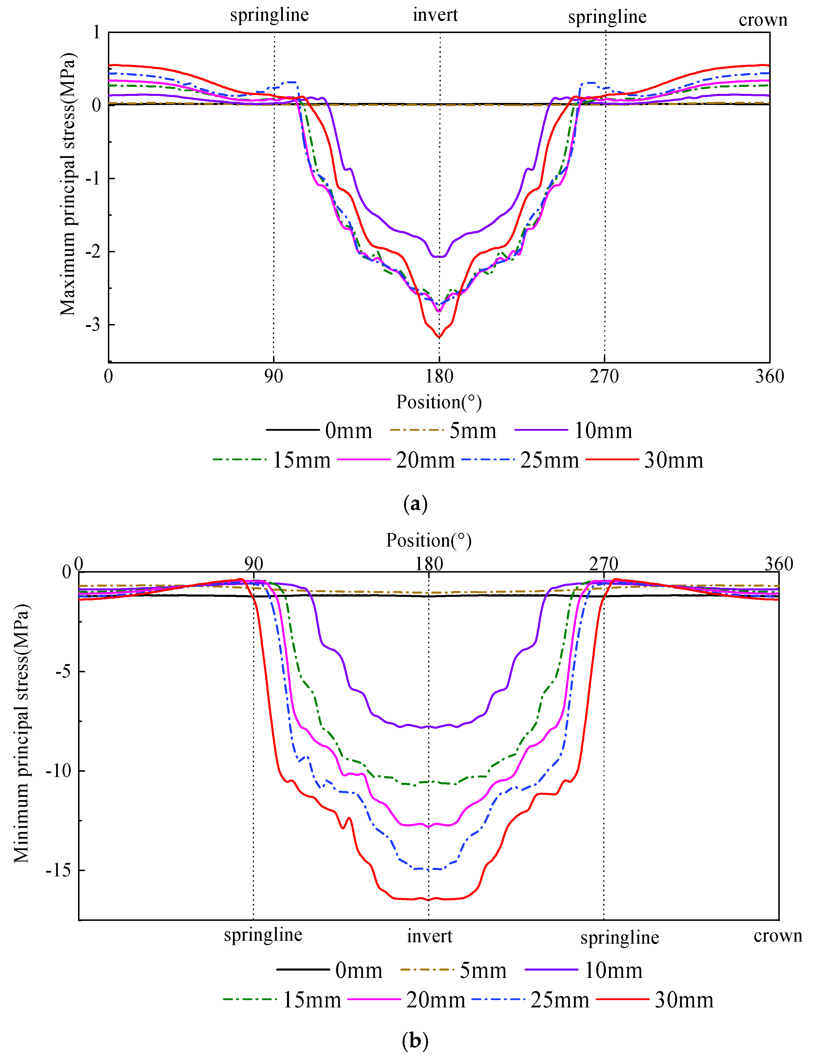
Figure 9a presents the distribution of the maximum principal stress in the concrete at the spigot-end cross-section. As shown in the figure, under different offsets, the maximum principal stress in the spigot concrete is symmetrically distributed along the cross-section centerline. Tensile stress is concentrated at the crown, whereas the springline and invert remain in compression, with no tensile stress present. The maximum tensile stress in the spigot cross-section is much smaller than that in the bell cross-section. When the offset is less than 15 mm, the tensile stress in the spigot cross-section remains relatively low, with a maximum value of only 0.29 MPa. When the offset increases to 30 mm, the maximum tensile stress occurs at the crown and reaches 0.55 MPa, still far below the tensile strength of concrete.
Figure 9b shows the distribution of the minimum principal stress in the concrete at the spigot-end cross-section. It can be observed that under different offsets, the minimum principal stress is symmetrically distributed along the cross-section centerline. The compressive stress in the upper part of the spigot cross-section is relatively small, not exceeding 2.00 MPa, while the compressive stress increases progressively toward the invert. This is because when vertical offset occurs between pipes, the spigot invert comes into contact with and is compressed by the steel ring of the following pipe, resulting in much higher compressive stress at the invert than elsewhere. When the offset does not exceed 10 mm, the overall compressive stress in the spigot concrete is relatively low, with a maximum of only 1.22 MPa. As the offset increases further, the maximum compressive stress in the spigot concrete begins to rise sharply, reaching 16.50 MPa at an offset of 30 mm, which is still below the compressive strength of the concrete.
4.1.2. Analysis of the Steel Ring
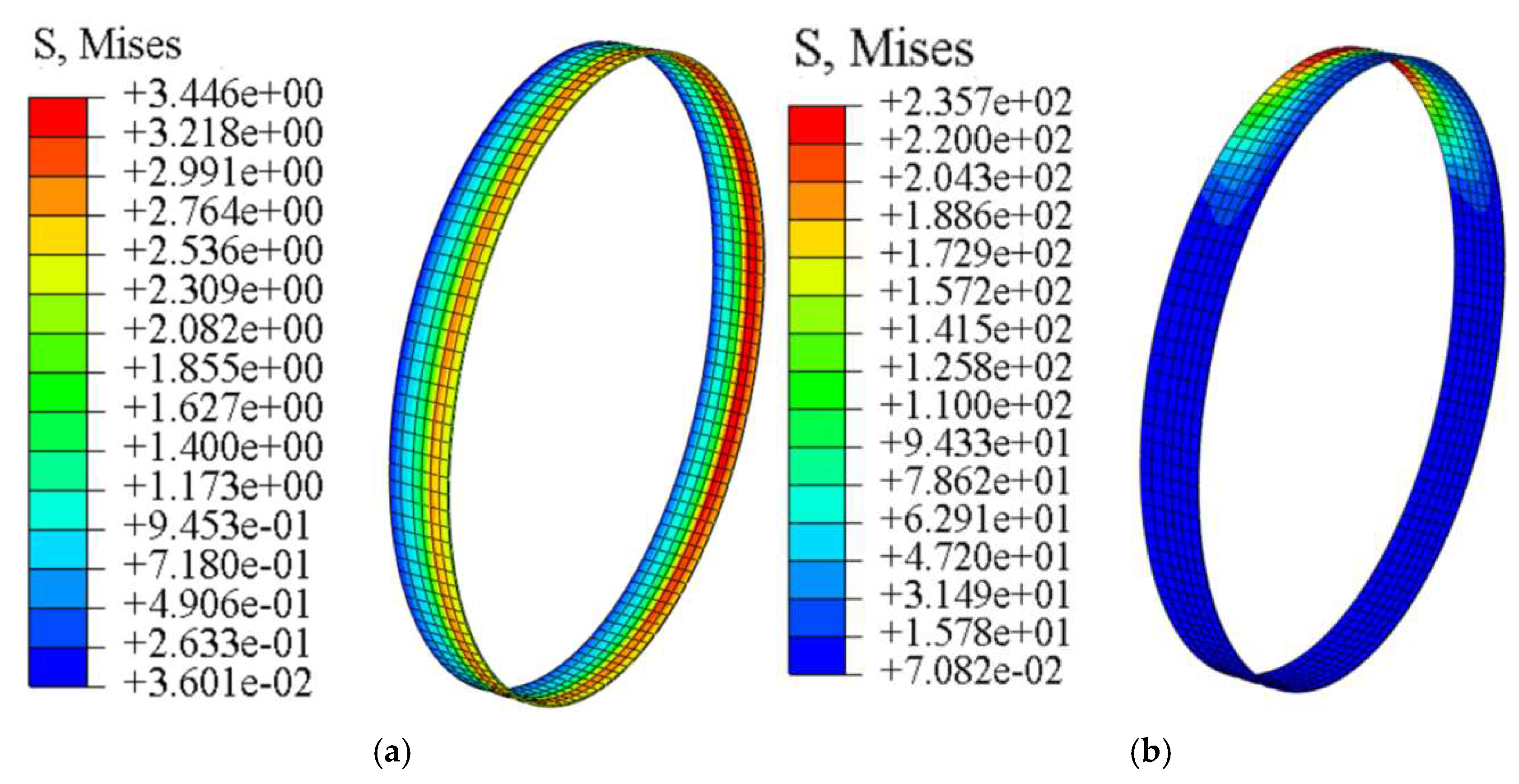
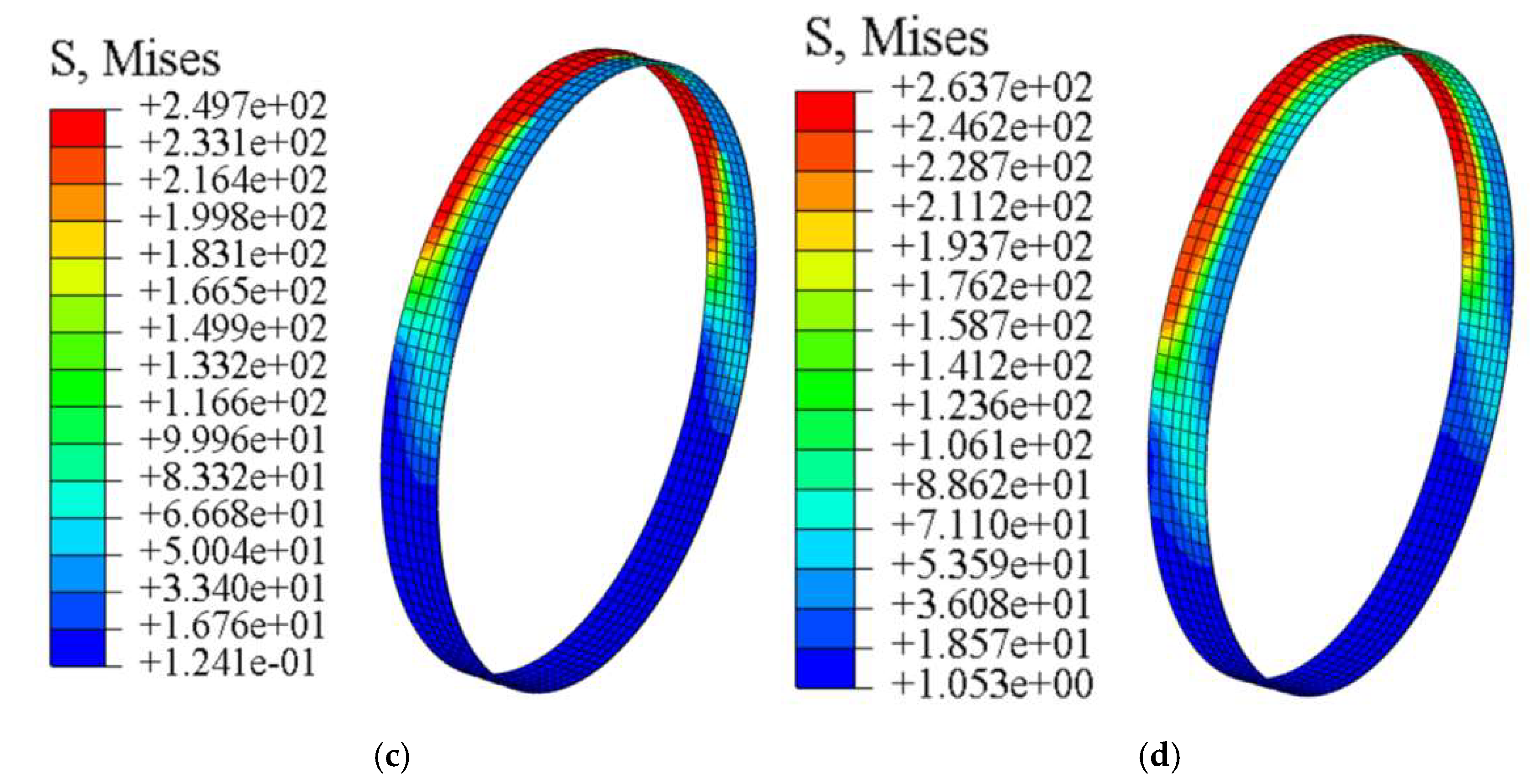
Figure 10 shows the contours of the von Mises stress in the steel ring under different offset magnitudes. As shown in the figure, when no offset is present between pipes, the stress in the steel ring is uniformly distributed along the circumferential direction. The bell-and-spigot joint is subjected to the axial jacking force transmitted from the preceding pipe, causing compressive deformation of the bell concrete and its contact with the steel ring. As a result, the stress at the connection between the steel ring and the pipe body becomes noticeably higher, with the maximum von Mises stress reaching 3.4 MPa. When the offset increases to 10 mm, the steel ring came into full contact with the spigot concrete of the preceding pipe, resulting in significant compressive interaction and a sharp increase in the stress within the steel ring. The maximum stress occurred at the top of the steel ring, reaching 235.7 MPa. As the joint offset continued to increase, the steel ring reached the yielding stage, and the warping deformation at the contact zone with the spigot of the preceding pipe became significantly more pronounced. The von Mises stress showed a slight increase compared with that observed at an offset of 10 mm. When the offset reached 30 mm, the von Mises stress at the crown of the steel ring increased to 263.7 MPa, which substantially exceeds the yield strength of Q235 steel.
4.2. Effect of Jacking Forces Under Offset
During pipe-jacking construction, the jacking force inevitably increases with the advance of the drive, and the magnitude of the jacking force directly affects the stress distribution in the joint region of the pipe [
36,
37,
38]. Field investigations indicate that the jacking force used in practical projects typically ranges from 4000 to 8000 kN. Therefore, in this study, three working conditions with jacking forces of 4000 kN, 6000 kN, and 8000 kN were established to analyze the influence of offset on the stress response of the bell and spigot joint under different jacking force levels.
4.2.1. Analysis of Stress in the Concrete at Joints
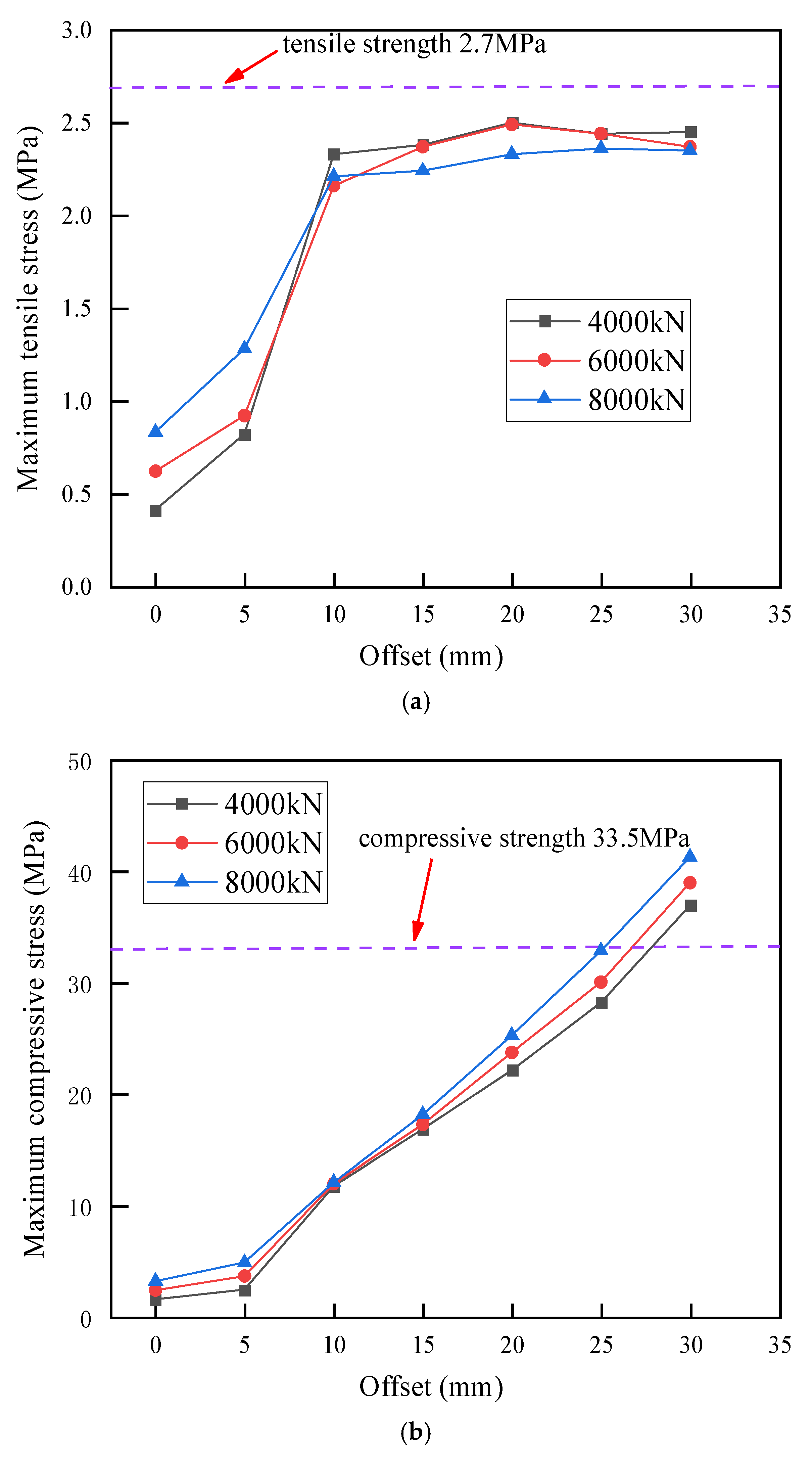
Figure 11a presents the variation curves of the maximum tensile stress in the bell concrete with respect to offset under different jacking forces. As shown in the figure, the variation trends are generally consistent across different jacking force levels: when the offset is less than 15 mm, the maximum tensile stress in the bell-end concrete increases rapidly with the growth of the joint offset, whereas beyond 15 mm, the growth rate of tensile stress gradually levels off. When no offset is present, the maximum tensile stresses under jacking forces of 4000 kN, 6000 kN, and 8000 kN are 0.41 MPa, 0.62 MPa, and 0.83 MPa, respectively. When the offset reaches 15 mm, the maximum tensile stresses under the three jacking forces increase to 2.38 MPa, 2.38 MPa, and 2.24 MPa, corresponding to increases of 480.5%, 282.3%, and 169.9% relative to the case with zero offset. When the offset further increases to 30 mm, the maximum tensile stresses become 2.45 MPa, 2.38 MPa, and 2.35 MPa, which represent only slight increases of 0.07 MPa, 0.01 MPa, and 0.11 MPa compared with those at 15 mm offset.
Figure 11b shows the variation curves of the maximum compressive stress in the bell concrete with respect to offset under different jacking forces. It can be observed that the maximum compressive stress increases sharply as the offset increases. When the offset does not exceed 5 mm, the maximum compressive stresses under all three jacking forces remain relatively low, with the largest value reaching only 4.89 MPa. When the offset exceeds 15 mm, the maximum compressive stress increases significantly. At an offset of 25 mm, the maximum compressive stresses under jacking forces of 4000 kN and 6000 kN are 28.24 MPa and 30.08 MPa, respectively, while that under 8000 kN reaches 32.90 MPa, which is extremely close to the compressive strength of C50 concrete (33.50 MPa), indicating a high likelihood of compressive failure at the bell. When the offset further increases to 30 mm, the maximum compressive stresses under all three jacking forces substantially exceed the compressive strength of the concrete, confirming that compressive crushing of the bell concrete would occur.
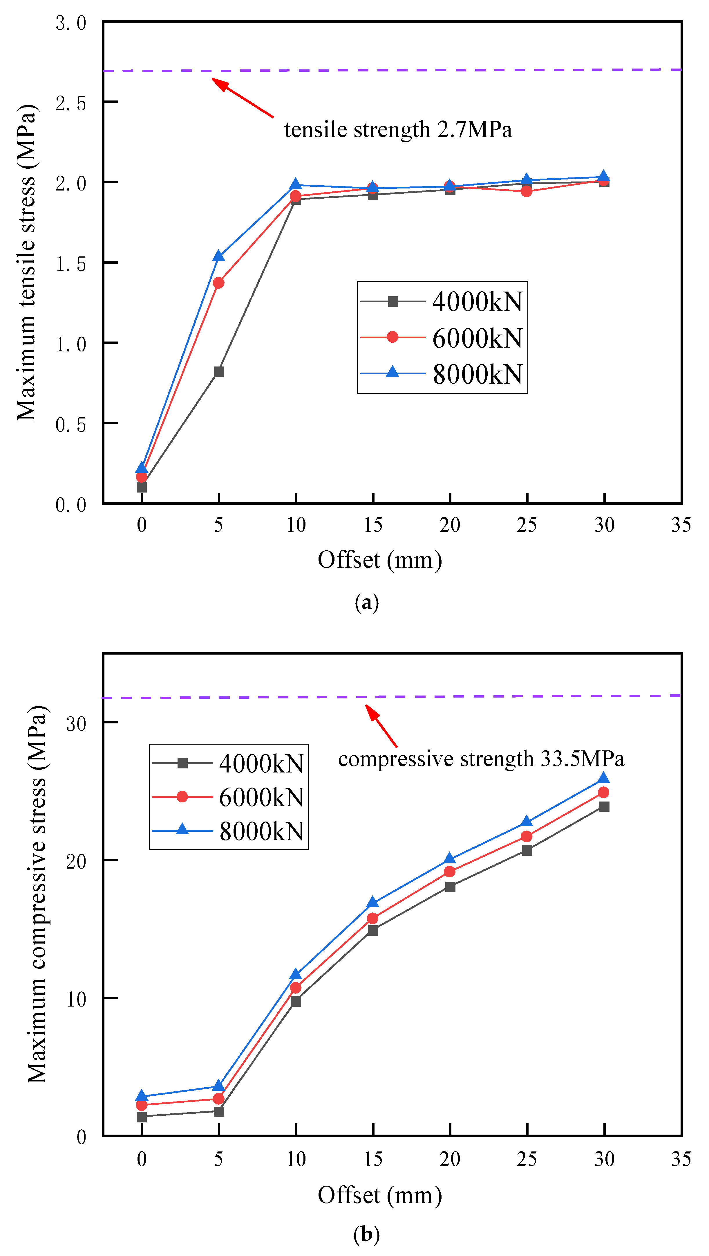
Figure 12a presents the variation curves of the maximum tensile stress in the spigot concrete with respect to offset under different jacking forces. When the offset is less than 15 mm, the tensile stress rises rapidly, whereas beyond 15 mm, the growth rate decreases significantly. When no offset is present, the maximum tensile stresses under jacking forces of 4000 kN, 6000 kN, and 8000 kN are 0.10 MPa, 0.16 MPa, and 0.21 MPa, respectively. When the offset reaches 15 mm, the maximum tensile stresses under the three jacking forces increase sharply to 1.92 MPa, 2.96 MPa, and 2.96 MPa. When the offset further increases to 30 mm, the maximum tensile stresses become 2.00 MPa, 2.01 MPa, and 2.03 MPa, respectively. The maximum tensile stress in the spigot-end concrete is slightly lower than that in the bell end, and both remain below the tensile strength of the concrete.
Figure 12b shows that the variation pattern of the maximum compressive stress in the spigot concrete is generally similar to that at the bell end. When the offset does not exceed 10 mm, the maximum compressive stresses under all three jacking forces remain relatively low, not exceeding 3.50 MPa. When the offset is greater than 5 mm, the maximum compressive stress in the spigot concrete exhibits a linear growth trend under all three jacking forces, and the growth rate increases significantly. The compressive stress at the spigot end is considerably lower than that at the bell end. At an offset of 30 mm, the maximum compressive stresses under jacking forces of 4000 kN, 6000 kN, and 8000 kN are 23.88 MPa, 24.89 MPa, and 25.86 MPa, respectively—all remaining below the compressive strength of concrete.
4.2.2. Analysis of the Steel Ring
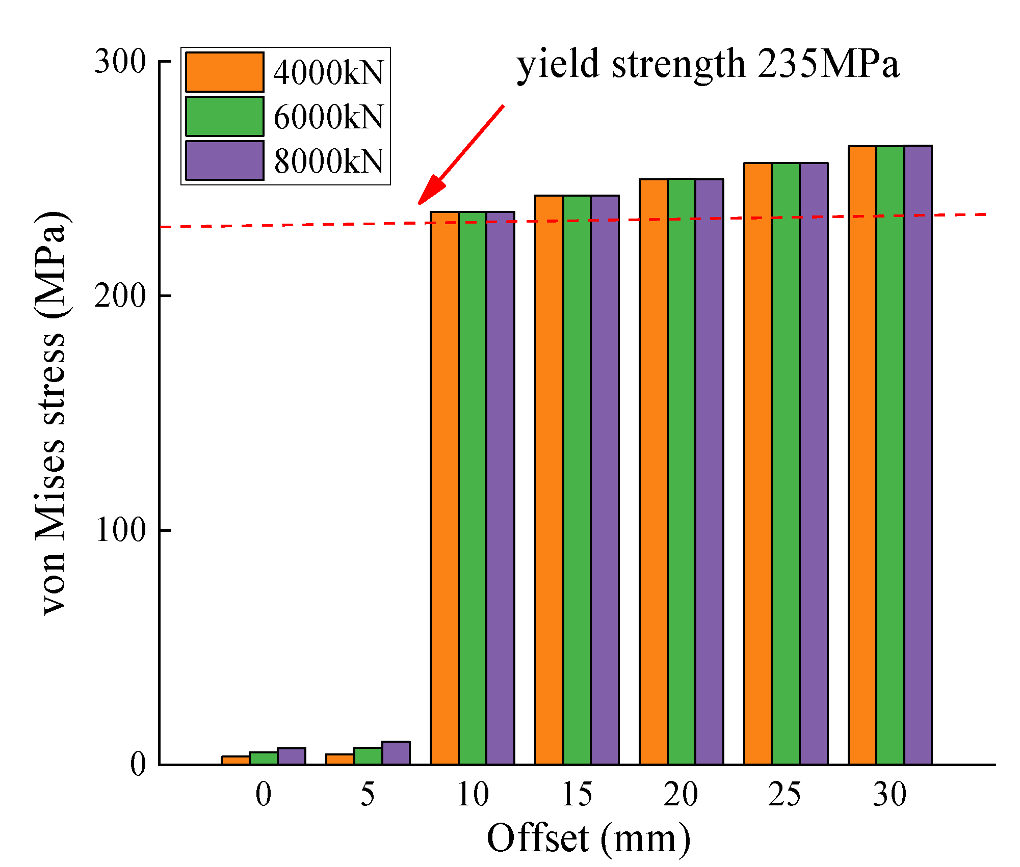
Figure 13 shows the variation of the von Mises stress in the steel ring with respect to offset under three different jacking forces. As illustrated, for the same offset, the von Mises stress in the steel ring remains nearly unchanged as the jacking force increases. This indicates that the magnitude of the jacking force has little effect on the stress state of the steel ring; the increase in steel ring stress is mainly attributed to its resistance to joint shear deformation. When the offset is 10 mm, the overall stress in the steel ring is relatively low under jacking forces of 4000 kN, 6000 kN, and 8000 kN, with the von Mises stress values of 11.61 MPa, 11.70 MPa, and 11.98 MPa, respectively, all remaining below 12 MPa. When the offset increases to 15 mm, the stress in the steel ring begins to grow exponentially, reaching 280.4 MPa, 281.3 MPa, and 281.7 MPa under the three jacking forces—approximately 24 times those at 10 mm offset. At this stage, the von Mises stress exceeds the yield strength of the steel, indicating that the steel ring has yielded. With a further increase in offset, the von Mises stress continues to rise rapidly, reaching a maximum value of approximately 780 MPa at an offset of 25 mm.
Based on the above analysis, it can be concluded that when an offset occurs between pipes, an increase in jacking force significantly amplifies the stress in the joint concrete but has only a minimal effect on the stress in the steel ring. When the offset reaches 10 mm, the steel ring yields under all three jacking force levels, whereas the concrete remains undamaged at this stage.
Table 3 presents the maximum compressive and tensile stresses of the joint concrete under different jacking forces and joint offsets. As shown in the table, the stress increase rate of the joint concrete rises significantly when the offset exceeds 5 mm. When the offset reaches 25 mm, under a jacking force of 8000 kN, the compressive stress of the joint concrete approaches the compressive strength of the concrete, indicating a high risk of structural failure. When the offset increases to 30 mm, the joint concrete has failed under all three jacking force conditions. To ensure construction safety, it is recommended that under jacking forces of 4000–6000 kN, the joint offset during construction should be limited to within 25 mm, whereas under a jacking force of 8000 kN, the offset should be limited to less than 20 mm.
5. Conclusions
To investigate the influence of offset on the mechanical behavior of pipe joints during pipe-jacking construction, a three-dimensional refined numerical model was developed based on the Wuhan Road pipe-jacking project. First, the effects of different offsets on the stress distribution of the bell concrete, spigot concrete, and steel ring were analyzed in detail. Subsequently, the influence of different jacking force levels on the joint stress under offset conditions was further examined, and recommended offset control values were proposed. The main conclusions are as follows:
(1) When an offset occurs between pipes, pronounced compressive stress concentration appears at the bell crown, while compressive stress concentration at the spigot invert is also evident. The location of the maximum tensile stress in the bell shifts from the haunch to the springline as the offset increases, whereas the maximum tensile stress in the spigot remains consistently located at the crown. The compressive stress in the bell concrete is higher than that in the spigot concrete. This is because, as the offset increases, the steel ring gradually comes into contact with and compresses the concrete at the spigot end of the adjacent pipe, causing warping deformation of the steel ring. As a result, the concrete at the connection between the steel ring and the bell is subjected to intensified compression, which is the primary cause of concrete failure.
(2) With increasing offset, the stresses in both the joint concrete and the steel ring increase progressively. When the offset does not exceed 5 mm, the stress growth in the concrete and steel ring remains relatively small. However, when the joint offset exceeds 5 mm, the compressive stress in the concrete and the von Mises stress in the steel ring begin to exhibit an explosive increase.
(3) When offset occurs between pipes, increasing the jacking force significantly amplifies the stress in the joint concrete but does not noticeably increase the stress in the steel ring. This indicates that the stress in the steel ring is primarily induced by resisting the shear deformation of the joint caused by the offset, and that the effect of jacking force is minimal.
(4) When the offset reaches 25 mm, the compressive stress in the bell concrete under an 8000 kN jacking force reaches 32.90 MPa, which is close to the compressive strength of concrete, indicating a high risk of compressive failure. When the offset reaches 30 mm, compressive failure of the bell concrete occurs under all jacking forces in the range of 4000–8000 kN. To ensure the structural safety of the pipe-jacking system, it is recommended that the offset be limited to no more than 25 mm when the jacking force is in the range of 4000–6000 kN, and to no more than 20 mm when the jacking force is between 6000–8000 kN.
Author Contributions
Conceptualization, L.L.; Methodology, Y.Z. and S.H.; Software, Y.Z.; Validation, Y.Z. and F.W.; Formal analysis, Y.Z.; Investigation, F.W.; Resources, Q.C.; Data curation, W.L.; Visualization, W.L.; Supervision, L.L. and Y.Z.; Project administration, F.W. All authors have read and agreed to the published version of the manuscript.
Funding
This research was funded by the Metallurgical Corporation of China Ltd., grant number. Major R&D Projects of MCC (MCC Tech [2023] No.5-5).
Data Availability Statement
The original contributions presented in this study are included in the article. Further inquiries can be directed to the corresponding author.
Conflicts of Interest
L.L, W.L. and Q.C. were employed by China MCC5 Group Corp., Ltd. The remaining authors declare that the research was conducted in the absence of any commercial or financial relationships that could be construed as a potential conflict of interest.
References
- Qian, D.; Jiao, H.; Li, Z.; Zhu, Y.; Liu, J.; Chen, Z.; Gao, X.; Liu, H.; Tao, B.; Xu, Z. Ground Settlement Law, Jacking Force Prediction, and Control Countermeasures for Large-Section Rectangular Pipe Jacking of National Highway Underpass. Sustainability 2023, 15, 12888. [Google Scholar] [CrossRef]
- Luo, L.; Zhe, Q.; Liu, W.; Fang, Y.; Wang, F. Research on the Longitudinal Deformation of Segments Induced by Pipe-Jacking Tunneling over Existing Shield Tunnels. Buildings 2025, 15, 1394. [Google Scholar] [CrossRef]
- He, Y.; Cheng, J.; Shi, Z.; Zhang, B.; Chen, L.; Li, X.; Wang, X.; Zhang, P. Research on Axial Stress and Strain Characteristics of Reinforced-Concrete Curved Pipe Jacking in Power Tunnels. Buildings 2024, 14, 3030. [Google Scholar] [CrossRef]
- Luo, Z.; Zhang, Y.; Chen, J.; Ou, X.; Zhang, X. Stress and Deformation Response of Pipe Jacking in Upper-Soft and Lower-Hard Strata: A Case Study in Changsha. Eng. Fail. Anal. 2024, 166, 108879. [Google Scholar] [CrossRef]
- Zhou, H.; Huang, S.; Ma, B.; Zhao, Y.; Tan, X.; Zhang, H. Prestressed Steel Wires Impact on Axial Bearing Capacity of Ultra-Large Section Jacking Prestressed Concrete Cylinder Pipe (JPCCP): Field Experiment and Simulation. Eng. Fail. Anal. 2025, 167, 109046. [Google Scholar] [CrossRef]
- Jiang, K.; Huang, L.; Liang, Y. Analysis on the Mechanical characteristics of long curve pipe jacking tunnel. J. Railw. Sci. Eng. 2021, 18, 2963–2970. [Google Scholar] [CrossRef]
- Zhou, H.; Chen, X.; Zhao, Y.; Zhang, H.; Ma, B.; Huang, S.; Wang, F.; Mi, R. Mechanical Performance of Ultra-Large-Section Jacking Prestressed Concrete Cylinder Pipe (JPCCP): A Case Study of Flood Diversion Pipeline in Zhengzhou, China. Tunn. Undergr. Space Technol. 2025, 165, 106841. [Google Scholar] [CrossRef]
- Geng, Z.; Jin, D.; Yuan, D.; Wang, Q.; Qiao, G. Study on Ground Deformation and Settlement Caused by the Construction of Pipe Jacking Tunnel in Multi-layer Strata. Tunn. Undergr. Space Technol. 2025, 165, 106856. [Google Scholar] [CrossRef]
- Tian, X.; Shen, X.; Song, Z.; Ma, P.; Fan, S. Deformation and Control Measures of Existing Metro Shield Tunnels Induced by Large-Section Pipe Jacking over-Crossing: A Case Study. Buildings 2025, 15, 2105. [Google Scholar] [CrossRef]
- Ma, P.; Shimada, H.; Sasaoka, T.; Moses, D.N.; Matsumoto, F.; Chen, X. Investigation on the Engineering Effects of the Geometrical Configuration of the Jacking Rectangular Pipe. Tunn. Undergr. Space Technol. 2022, 119, 104239. [Google Scholar] [CrossRef]
- Najafi, M.; Ramirez, G.; Mielke, R.; Keil, B.; Davidenko, G.; Rahman, S.; Jain, A. Design, Analysis, and Full-Scale Testing of the Rolled Groove Gasket Joint System in AWWA C303 Bar-Wrapped, Steel-Cylinder Concrete Pressure Pipe. J. Pipeline Syst. Eng. Pract. 2013, 4, 156–169. [Google Scholar] [CrossRef]
- Cui, Q.-L.; Xu, Y.-S.; Shen, S.-L.; Yin, Z.-Y.; Horpibulsuk, S. Field Performance of Concrete Pipes during Jacking in Cemented Sandy Silt. Tunn. Undergr. Space Technol. 2015, 49, 336–344. [Google Scholar] [CrossRef]
- Wadood, A.; McCabe, B.A.; Sheil, B.B. Field Monitoring and Instrumentation in Microtunnelling/Pipe Jacking: A Review and Future Directions. Undergr. Space 2025, 22, 225–240. [Google Scholar] [CrossRef]
- Gan, B.-L.; Zhang, D.-M.; Huang, Z.-K.; Zheng, F.-Y.; Zhu, R.; Zhang, W. Ontology-Driven Knowledge Graph for Decision-Making in Resilience Enhancement of Underground Structures: Framework and Application. Tunn. Undergr. Space Technol. 2025, 163, 106739. [Google Scholar] [CrossRef]
- Liu, S.-C.; Peng, F.-L.; Qiao, Y.-K.; Zhang, J.-B. Evaluating Disaster Prevention Benefits of Underground Space from the Perspective of Urban Resilience. Int. J. Disaster Risk Reduct. 2021, 58, 102206. [Google Scholar] [CrossRef]
- Zhong, Z.; Wang, Q.; Xiong, Y. Stress and Deformation Mechanism of Jacking Prestressed Concrete Cylinder Pipe under Axial Jacking Force. Eng. Fail. Anal. 2024, 159, 108097. [Google Scholar] [CrossRef]
- Gong, Q.; Zhu, H.; Yan, Z.; Huang, B.; Zhang, Y.; Dong, Z. Fracture and Delamination Assessment of Prestressed Composite Concrete for Use with Pipe Jacking Method. Math. Probl. Eng. 2015, 2015, 579869. [Google Scholar] [CrossRef]
- Zhao, Y.; Luo, F.; Xiong, L. Monitoring and Analysis of Circumferential Pressure for Long-distance Pipe Jacking Construction in Composite Strata. Eng. Rep. 2025, 7, e13066. [Google Scholar] [CrossRef]
- Zhang, P.; Feng, X.; Zeng, C.; Ariaratnam, S. Field Performance of Steel Pipes During Curve Jacking in Gongbei Tunnel. Tunn. Undergr. Space Technol. 2022, 128, 104585. [Google Scholar] [CrossRef]
- Li, C.; Zhong, Z.; Bie, C.; Liu, X. Field Performance of Large Section Concrete Pipes Cracking During Jacking in Chongqing–A Case Study. Tunn. Undergr. Space Technol. 2018, 82, 568–583. [Google Scholar] [CrossRef]
- Xu, Y.; Pang, Y.; Zhang, C.; Kang, J.; Huang, Z. Shear Performance of F-type Socket Joint in Rectangular Pipe Jacking Tunnel. J. Zhejiang Univ. Eng. Sci. 2023, 57, 957–966. [Google Scholar] [CrossRef]
- Xu, Y.; Kang, J.; Zhang, C.; Huang, Z.; Zhang, X. Shear Failure Mechanism of F-type Socket-and-Spigot Joint in Rectangular Pipe Jacking Tunnels. Mod. Tunn. Technol. 2023, 60, 189–198. [Google Scholar] [CrossRef]
- Xu, Y.; Kang, J.; Zhang, C.; Pang, Y.; Huang, Z.; Zhang, X. Shear Stiffness Analysis of F-Socket Joint in Rectangular Pipe Jacking Tunnel. China Railw. Sci. 2024, 45, 113–122. [Google Scholar] [CrossRef]
- Xu, Y.; Xu, C.; Zhang, C.; Zhang, X. Bending Performance of F-Type Socket Joints for Rectangular Pipe Jacking Tunnels with Longitudinal Connectors. Buildings 2024, 14, 3758. [Google Scholar] [CrossRef]
- Wu, H.; Zhai, K.; Fang, H.; Wang, F.; Yu, X.; Li, B. Bell-and-Spigot Joints Mechanical Properties Study of PCCP under the Uneven Settlement of Foundation: Simulation and Full-Scale Test. Structures 2022, 43, 1692–1703. [Google Scholar] [CrossRef]
- Becerril García, D.; Moore, I.D. Behaviour of Bell and Spigot Joints in Buried Reinforced Concrete Pipelines. Can. Geotech. J. 2015, 52, 609–625. [Google Scholar] [CrossRef]
- Liu, K.; Chen, X.; Zhang, P.; Ma, B.; Feng, X.; Zhang, Y.; Liu, H.; Tan, X.; Xu, T. Axial Mechanical Response of Concrete Pipe Jacking Considering the Deflection of the Bell-and-Spigot Joint: Full-Scale Test and Numerical Simulation. Tunn. Undergr. Space Technol. 2024, 149, 105805. [Google Scholar] [CrossRef]
- Tong, K.; Yang, C.; Gao, Z.; Huang, X. Mechanical Response and Influencing Factors on Pipe Jacking under Eccentric Load. Chin. J. Undergr. Space Eng. 2020, 16, 1459–1466. [Google Scholar]
- Xu, Y.; Pei, X.; Dong, W.; Huang, Z.; Kang, J. Waterproof Safety Limit of Rubber Rings of Rectangular Pipe Jacking Tunnel Joints. Tunn. Constr. 2022, 42, 388. [Google Scholar] [CrossRef]
- Chen, P. Study on Mechanical Properties of Multi-scale Polypropylene Fiber Reinforced Concrete Pipe Jacking. Master’s Thesis, Chongqing University, Chongqing, China, 2021. [Google Scholar]
- Deng, Z. Experimental and Analytical Study of Construction Mechanics Effect of an Extra-Long Distance Rock Pipe Jacking Through Rock Strata Under Complex Contact Condition. Ph.D. Thesis, Chongqing University, Chongqing, China, 2020. [Google Scholar]
- Kang, J. Research on Shear Deformation Mechanism and Control Standard of F-Type Socket Joint in Rectangular Pipe Jacking Tunnel. Master’s Thesis, Inner Mongolia University of Science and Technology, Baotou, China, 2022. [Google Scholar]
- Xu, Y.; Xu, C.; Zhang, C.; Zhang, X. Experimental and Numerical Study on the Mechanical Properties of F Type Socket Joints for Rectangular Pipe Jacking with Steel Screw Connection. Sci. Rep. 2024, 14, 30952. [Google Scholar] [CrossRef]
- Li, Y. Study on Mechanical Properties of Concrete Pipe Joint with Large Section in Long Distance Pipe Jacking Engineering. Master’s Thesis, Chongqing University, Chongqing, China, 2020. [Google Scholar]
- GB 50268-2008; Specification for Construction and Acceptance of Water Supply and Drainage Pipeline Projects. Beijing Municipal Construction Group Co., Ltd.: Beijing, China, 2008.
- Yang, Y.; Liu, Y.; Zhang, J.; Zhang, Z.; Li, Q. Jacking Force Prediction for Long-Distance Pipe by Integrating Physical Information and Adversarial Learning Mechanism. Buildings 2025, 15, 1337. [Google Scholar] [CrossRef]
- Kong, C.; Guan, G.; Gu, S.; Zhou, Z.; Wang, H. Frictional Resistance Calculation and Jacking Force Prediction of Rectangular Pipe Jacking. Sci. Rep. 2023, 13, 14992. [Google Scholar] [CrossRef] [PubMed]
- Liu, T.; Liu, J.; Tan, Y.; Fan, D. Prediction of Jacking Force for Construction of Long-Distance Rectangular Utility Tunnel Using Differential Evolution–Bidirectional Gated Re-Current Unit–Attention Model. Buildings 2024, 14, 3169. [Google Scholar] [CrossRef]
Figure 1.
Pipe jacking construction site ((a) Pipe Jacking, (b) Reinforced Concrete Pipe).
Figure 1.
Pipe jacking construction site ((a) Pipe Jacking, (b) Reinforced Concrete Pipe).
Figure 2.
Schematic diagram of joint detail dimensions.
Figure 2.
Schematic diagram of joint detail dimensions.
Figure 3.
Numerical model and mesh of pipe.
Figure 3.
Numerical model and mesh of pipe.
Figure 4.
Numerical model.
Figure 4.
Numerical model.
Figure 5.
Contours of maximum principal stress of pipe under different offsets ((a) 0 mm, (b) 10 mm, (c) 20 mm, (d) 30 mm).
Figure 5.
Contours of maximum principal stress of pipe under different offsets ((a) 0 mm, (b) 10 mm, (c) 20 mm, (d) 30 mm).
Figure 6.
Contours of minimum principal stress of pipe under different offsets ((a) 0 mm, (b) 10 mm, (c) 20 mm, (d) 30 mm).
Figure 6.
Contours of minimum principal stress of pipe under different offsets ((a) 0 mm, (b) 10 mm, (c) 20 mm, (d) 30 mm).
Figure 7.
Arrangement of stress extraction paths and cross-section locations.
Figure 7.
Arrangement of stress extraction paths and cross-section locations.
Figure 8.
Stress distribution at cross-section of bell joint ((a) maximum principal stress, (b) minimum principal stress).
Figure 8.
Stress distribution at cross-section of bell joint ((a) maximum principal stress, (b) minimum principal stress).
Figure 9.
Stress distribution at cross-section of spigot joint ((a) maximum principal stress, (b) minimum principal stress).
Figure 9.
Stress distribution at cross-section of spigot joint ((a) maximum principal stress, (b) minimum principal stress).
Figure 10.
Contours of von Mises stress of steel ring under different offsets: (a) 0 mm, (b) 10 mm, (c) 20 mm, (d) 30 mm.
Figure 10.
Contours of von Mises stress of steel ring under different offsets: (a) 0 mm, (b) 10 mm, (c) 20 mm, (d) 30 mm.
Figure 11.
Concrete stress of bell joint under different jacking forces ((a) maximum tensile stress, (b) maximum compressive stress).
Figure 11.
Concrete stress of bell joint under different jacking forces ((a) maximum tensile stress, (b) maximum compressive stress).
Figure 12.
Concrete stress of spigot joint under different jacking forces ((a) maximum tensile stress, (b) maximum compressive stress).
Figure 12.
Concrete stress of spigot joint under different jacking forces ((a) maximum tensile stress, (b) maximum compressive stress).
Figure 13.
Von Mises stress of steel ring under different jacking forces.
Figure 13.
Von Mises stress of steel ring under different jacking forces.
Table 1.
CDP model parameters.
Table 1.
CDP model parameters.
| Eccentricity | fb0/fco | Dilation Angle (ψ) | Kc | Viscosity Parameter
(μ) |
|---|
| 0.1 | 1.16 | 36 | 0.667 | 33.5 |
Table 2.
Physical and mechanical properties of various materials in the model.
Table 2.
Physical and mechanical properties of various materials in the model.
| Materials | Density
(kg/m3) | Elastic Modulus
(MPa) | Poisson’s Ratio
(μ) | Compressive
Strength
(MPa) | Tensile Strength
(MPa) | Yield Strength
(MPa) | Ultimate Strength
(MPa) |
|---|
| Concrete | 2460 | 34,500 | 0.2 | 33.5 | 2.7 | - | - |
| Steel ring | 7850 | 206,000 | 0.3 | - | - | 235 | 370 |
| Reinforcement cage | 7850 | 206,000 | 0.3 | - | - | 400 | 540 |
| Wooden cushion | 600 | 100 | 0.25 | - | - | - | - |
Table 3.
The maximum compressive and tensile stresses of the joint concrete under different jacking forces and joint offsets.
Table 3.
The maximum compressive and tensile stresses of the joint concrete under different jacking forces and joint offsets.
| Jacking Force | Stress | 0 mm | 5 mm | 10 mm | 15 mm | 20 mm | 25 mm | 30 mm |
|---|
| 4000 kN | maximum tensile stress (MPa) | 0.41 | 0.82 | 2.33 | 2.38 | 2.50 | 2.44 | 2.45 |
| maximum compressive stress (MPa) | 1.59 | 2.45 | 11.78 | 16.88 | 22.17 | 28.24 | 36.97 |
| 6000 kN | maximum tensile stress (MPa) | 0.62 | 0.92 | 2.16 | 2.37 | 2.49 | 2.44 | 2.37 |
| maximum compressive stress (MPa) | 2.41 | 3.68 | 11.99 | 17.28 | 23.76 | 30.08 | 39.02 |
| 8000 kN | maximum tensile stress (MPa) | 0.83 | 1.28 | 2.21 | 2.24 | 2.33 | 2.36 | 2.35 |
| Disclaimer/Publisher’s Note: The statements, opinions and data contained in all publications are solely those of the individual author(s) and contributor(s) and not of MDPI and/or the editor(s). MDPI and/or the editor(s) disclaim responsibility for any injury to people or property resulting from any ideas, methods, instructions or products referred to in the content. |
© 2025 by the authors. Licensee MDPI, Basel, Switzerland. This article is an open access article distributed under the terms and conditions of the Creative Commons Attribution (CC BY) license (https://creativecommons.org/licenses/by/4.0/).

