Article

Centrifugal Model Test Study on the Influence of Subgrade Filling on Adjacent Bridge Pile Foundations

1
School of Highway, Chang’an University, South Second Ring Rd., Yanta District, Xi’an 710064, China
2
National Key Laboratory of Green and Long-Life Road Engineering in Extreme Environment, CCCC First Highway Consultants Co., Ltd., Xi’an 710075, China
*
Author to whom correspondence should be addressed.
Buildings 2025, 15(22), 4162; https://doi.org/10.3390/buildings15224162
Submission received: 14 October 2025 / Revised: 10 November 2025 / Accepted: 12 November 2025 / Published: 19 November 2025
(This article belongs to the Section Building Structures)

Abstract

A series of centrifuge model tests was performed to investigate the influence of subgrade surcharge loading on adjacent bridge pile foundations in soft soils, based on the Mingu Road project in Zhongshan City, China. Four surcharge distances (1D, 2D, 3D, and 4D, where D is the pile diameter) were examined to clarify the spatial–temporal evolution of pile–soil interaction. The results show that horizontal displacement, bending moment, and lateral soil resistance of the pile increase over time, exhibiting significant time-dependent behavior characterized by rapid initial growth followed by stabilization. As the surcharge distance increases, these responses decrease markedly, indicating a strong spatial attenuation effect. The bending moment along the pile depth follows a unimodal pattern with a peak at the soft soil layer. In contrast, the lateral soil resistance exhibits a similar trend of increase and decrease with depth. When the surcharge distance exceeds approximately 4D, the additional influence on the pile response becomes small. This study provides physical evidence and theoretical support for the safe design and construction of bridge pile foundations adjacent to road embankments in areas with soft soil.

1. Introduction

In China, the rapid expansion of infrastructure construction has led to a significant increase in road–bridge parallel and road–bridge intersection projects. In conventional engineering practice, to minimize the adverse influence of construction activities on existing bridge structures, the embankment and pavement are typically completed before the bridge construction [1,2,3,4,5]. However, due to constraints such as urban planning adjustments, design coordination, and construction scheduling, situations often arise in which bridge pile foundations are constructed before the embankment or concurrently with the bridge and subgrade [6,7,8,9]. Under such circumstances, subsequent embankment filling can impose additional lateral soil pressure on the completed bridge pile foundations, leading to unfavorable responses, such as pile deflection, horizontal displacement, and vertical settlement. In severe cases, these interactions may compromise the overall stability and serviceability of bridge structures [10,11,12,13,14,15,16].
Numerous studies have investigated the deformation and stress behavior of pile foundations subjected to surcharge loading in soft soils. Dong et al. [17], using the Mali River Bridge project as a case study, analyzed the stress and deformation characteristics of bridge pile foundations adjacent to tall embankments and demonstrated that load reduction and anti-slide piles can effectively control pile displacement. Deng et al. [18] conducted field monitoring and revealed that surcharge loading induces negative skin friction around the pile, which evolves progressively with time. Feng et al. [19] combined field tests and numerical modeling to propose an in situ solidification and composite foundation technique that effectively mitigates horizontal displacement and bending moments, thereby enhancing the stability of pile foundations. Ding et al. [20] conducted field loading tests at the Ningbo North Freight Station and found that the surcharge height and horizontal distance significantly affect the internal forces and deformations of the piles, exhibiting strong time-dependent behavior. Liu [21] further clarified the mechanism of negative skin friction through single- and double-pile model tests, demonstrating its progressive increase during consolidation. Yuan et al. [22] explored the long-term effect of coal stockpile loads through centrifuge model testing, confirming the influence of sustained surcharge on foundation settlement and pile stress distribution.
Although these studies have provided valuable theoretical and practical insights into surcharge-induced pile responses, several critical limitations remain. First, most investigations have focused on single geological or boundary conditions, lacking systematic evaluation under complex stratified foundations and long-term surcharge effects. Second, the existing understanding of the deformation and failure mechanisms of pile foundations under combined surcharge loading and soil heterogeneity remains incomplete. Third, while field tests, numerical simulations, and theoretical analyses have been widely used, centrifuge model testing—capable of reproducing prototype stress conditions under controlled scaling laws—has been less frequently employed. Field monitoring is often restricted by site accessibility and safety considerations, whereas theoretical and numerical models are subject to uncertainties in soil constitutive behavior. Centrifuge model testing, where the prototype is scaled by a factor of n and the centrifugal acceleration is increased to n·g, ensures that the stress field and self-weight conditions in the model correspond to those in the prototype. This approach maintains experimental controllability while reducing cost and time.
To overcome the limitations above, this study performs a series of centrifuge model tests to systematically investigate the mechanical response of adjacent bridge pile foundations under varying surcharge distances in soft soil. The research focuses on analyzing the temporal and spatial evolution of horizontal displacement, bending moment distribution, and soil resistance along the pile shaft. The findings aim to clarify the mechanism of surcharge–pile–soil interaction, providing both experimental evidence and theoretical guidance for the safe design and construction of pile foundations in road–bridge intersection projects.

2. Materials and Methods

2.1. Project Overview

Min Gu Road is situated in the northern region of Zhongshan City, Guangdong Province, within the land–sea interactive sedimentary plain—a typical landform of the Pearl River Delta.
The utilization of the East Outer Ring Expressway corridor is necessary for the area between Nansan Highway and Century Avenue due to constraints on controlling factors for agricultural protection land. Construction of the East Outer Ring Expressway, employing a full-bridge design, commenced in 2020. The road segment is situated beneath the expansive cantilever bridge of the expressway, as depicted in Figure 1. The geological composition in the project vicinity primarily comprises plain fill, silt, silty mucky clay, silty clay, and sand. Mucky soil layers are prevalent, characterized by their shallow depth and significant variability in thickness. The application of subgrade filling (surcharge) can induce lateral displacement of neighboring pile foundations.

2.2. Test Equipment and Data Collection

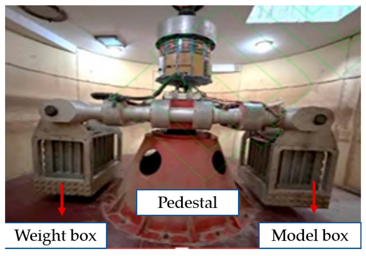
The experiment was conducted using the TLJ-3 geotechnical centrifuge model apparatus (Institute of General Engineering, China Academy of Engineering Physics, Mianyang, Sichuan, China) from Chang’an University. The apparatus is depicted in Figure 2, with its operational specifications detailed in Table 1.

2.3. Centrifuge Model Test Similarity Laws Tests

The mechanical properties of pile foundations are intricately linked to various factors, including their structural dimensions, material characteristics, and properties of the foundation and backfill soils, among others. To ensure a comprehensive alignment with centrifuge size, test setup conditions, and real-world engineering scenarios, a geometric similarity ratio of n = 60 has been determined. Table 2 presents the relationships among diverse parameters derived from dimensional analysis.

2.4. Design of the Model Pile

According to the specifications of the Mingu Road project, the prototype pile has a cross-sectional diameter of 1.8 m, a concrete strength grade of C30, and an elastic modulus of 30 GPa. In accordance with the scaling factor for the centrifuge model (n = 60), the model pile has a cross-sectional diameter of 30 mm and a wall thickness of 3.5 mm.
Considering the test conditions and material factors comprehensively, the main control factors for the model pile are the similarity in size, weight, volume ratio, and pile side friction resistance, with stiffness similarity as a secondary factor. The selected model pile for testing comprises a magnesium-aluminum alloy tube with a sealed bottom and an elastic modulus of approximately 70 GPa, mimicking a pile foundation. To replicate the pile’s roughness, a thin layer of mortar is applied to the surface of the pile. The deformation similarity ratio necessitates that the flexural strength of the model pile align with that of the prototype pile, as expressed by the following Equation (1):
n 2 E m I m = E p I p = n 4 E m D m o 4 - d m o 4 = E p D p o 4
In the equation, n represents the model scale; Em and Ep denote the elastic moduli of the model pile and the prototype pile; and Dmo, dmo, and Dpo stand for the outer diameter, inner diameter of the model pile, and diameter of the prototype pile, respectively.
Table 3 presents the flexural stiffness values for the model and prototype piles, indicating that the discrepancy between them falls within acceptable limits.

2.5. Model Deep Mixed Columns

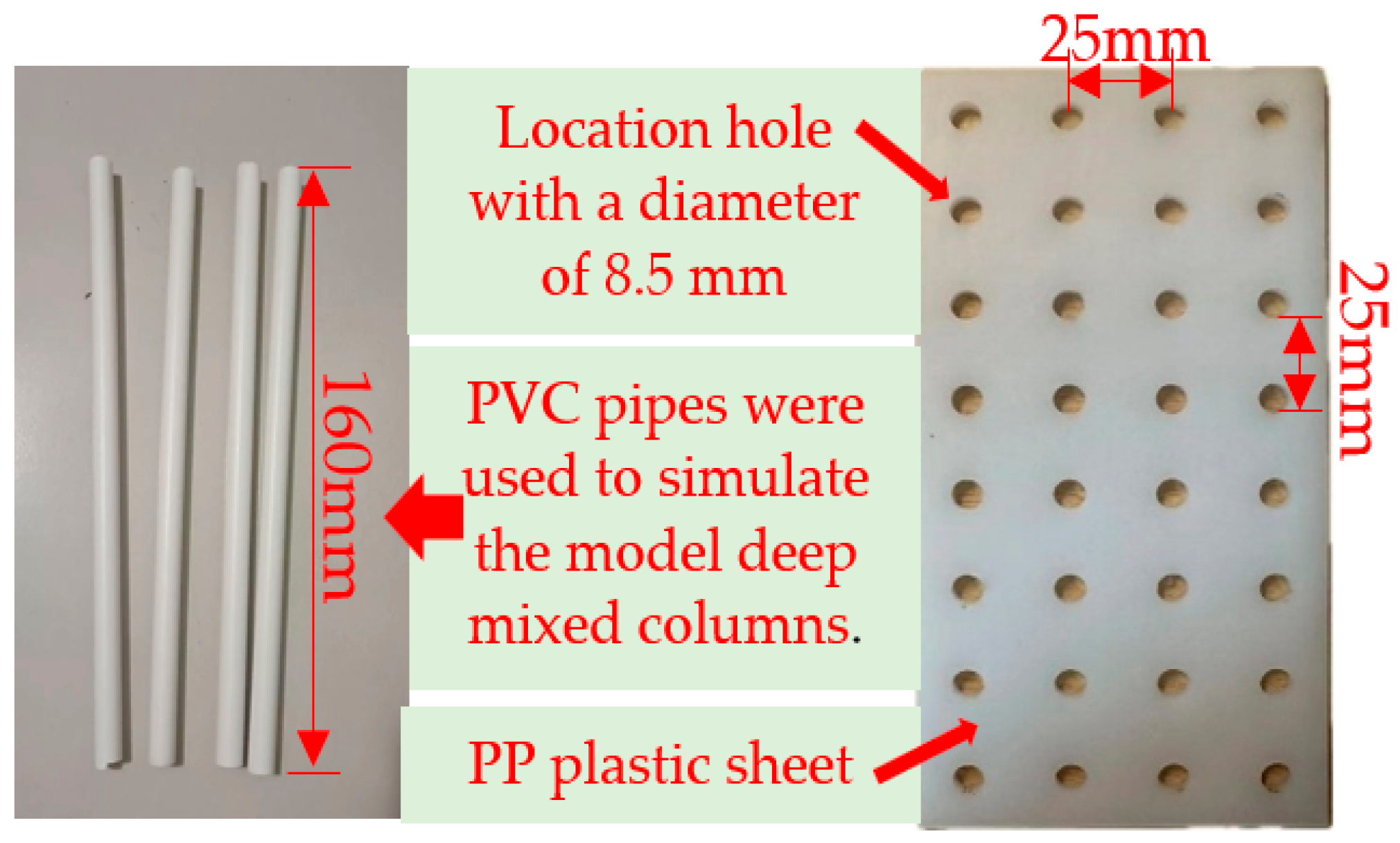
The prototype deep mixed columns material exhibits an elastic modulus of 0.5 GPa. PVC pipes have been chosen for the deep mixed columns in the experimental model. To meet the deformation-similarity ratio criteria, the flexural stiffness of the model’s deep mixed columns must match that of the prototype deep mixed columns (Figure 3).
Based on the model’s deep mixed columns, with a diameter of 8.3 mm and a wall thickness of 0.3 mm, Table 4 can be derived from the computations.

2.6. Soil Sample Preparation

In this study, soft soil was used to replicate the upper layer, well-graded sand for the intermediate layer, and a composite layer comprising soil, sand, and gravel for the lower layer, to mimic the highly weathered rock layer. The geological survey data informed the arrangement of soil layers in this investigation of the Mingu Road project section. Following numerous trial preparations and indoor geotechnical assessments (including moisture content testing, direct shear testing, compression testing, etc.) conducted at the Geotechnical Laboratory of the School of Highway at Chang’an University for validation, the parameters of each soil layer are detailed in Table 5.
The apparent cohesion of coarse sand (approximately 2 kPa) is attributed to slight suction and weak cementation between fine particles under partially saturated conditions, as well as the presence of a small amount of silt and clay fractions in the sand matrix.

2.7. Experimental Protocol

During the soil-filling process in the model test, compaction times are determined by density and moisture content, and each soil layer is limited to a maximum height of 5 cm. Once the soil layer at the base of the pile satisfies the boundary conditions, the model pile is positioned at the designated height, followed by incremental layer-by-layer soil filling. Subsequently, the planar position of the pile foundation is assessed using a ruler after each soil layer placement, and any deviations are promptly corrected to maintain the vertical alignment of the pile body. The distance between the model pile’s base and the model box’s bottom is 180 mm, with the top of the model pile extending 50 mm above the soil surface (Figure 4). For installing the model-deep mixed columns, a plastic positioning hole is initially used for accurate placement. To ensure precise pile positioning during insertion, holes must be pre-drilled on the plastic positioning plate. Subsequently, the plate is positioned on the foundation soil, and the piles are sequentially inserted into the pre-drilled holes on the positioning plate. It should be noted that in Figure 4, there is no overlapping area between the deep mixed columns and the bridge piles. After filling the model box, it is lifted into the centrifuge chamber. The installation of the vertical loading device, laser rangefinder, strain gauge lead connections, and soil pressure cells to the centrifuge plug is then carried out.
To investigate the effect of surcharge position on pile–soil interaction, four separate physical models were prepared, each corresponding to a different surcharge location. All models were independently constructed to ensure consistent soil properties, geometry, and boundary conditions for each test case. The symbol S in Figure 4 denotes the distance from the center of the bridge pile to the toe of the filled soil.

2.8. Data Collection and Processing

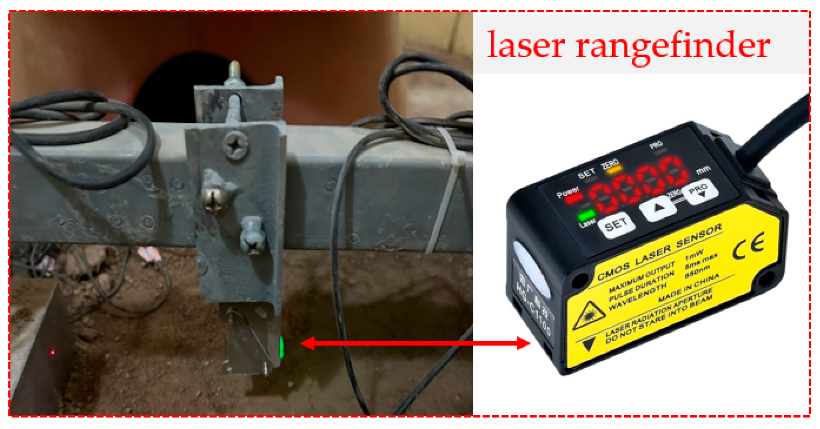
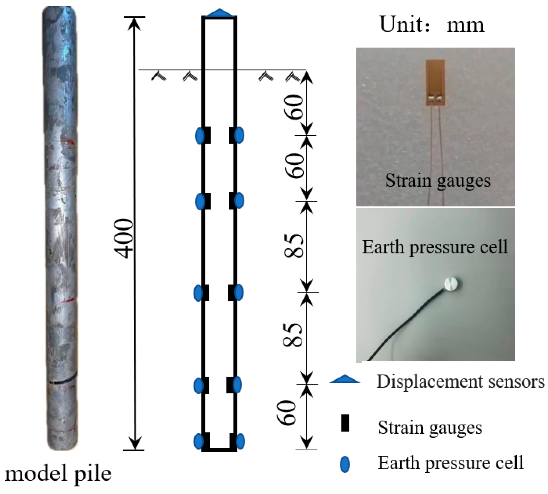
During the experimental testing, a laser rangefinder was used to measure the horizontal displacement of the pile head, as shown in Figure 5. Strain gauges of the BA120-05AA (Chengke Electronics Technology Co., Ltd., Shanghai, China) type were positioned symmetrically within the pile body on both the front and rear sides of the model pile in the radial orientation. Concurrently, earth pressure was monitored using the SY200 resistance miniature earth pressure cell (Mingyang Instrument Technology Co., Ltd., Changzhou, Jiangsu, China), with the distribution of measurement locations shown in Figure 6.
The experimental data obtained from the strain gauges include the compressive strain (εi) and tensile strain (εi+) measured on opposite sides of the pile cross-section. For any cross-section i, the distance between the compressive and tensile strain measurement points is assumed to be b (23 mm in this test, corresponding to the inner diameter of the model pile). The bending moment Mi at section i can be expressed as:
M = E I ( ε i + ε i ) b
where E is the elastic modulus of the model pile, I is the moment of inertia of the pile cross-section.

2.9. Transformation of Pile Body Displacement

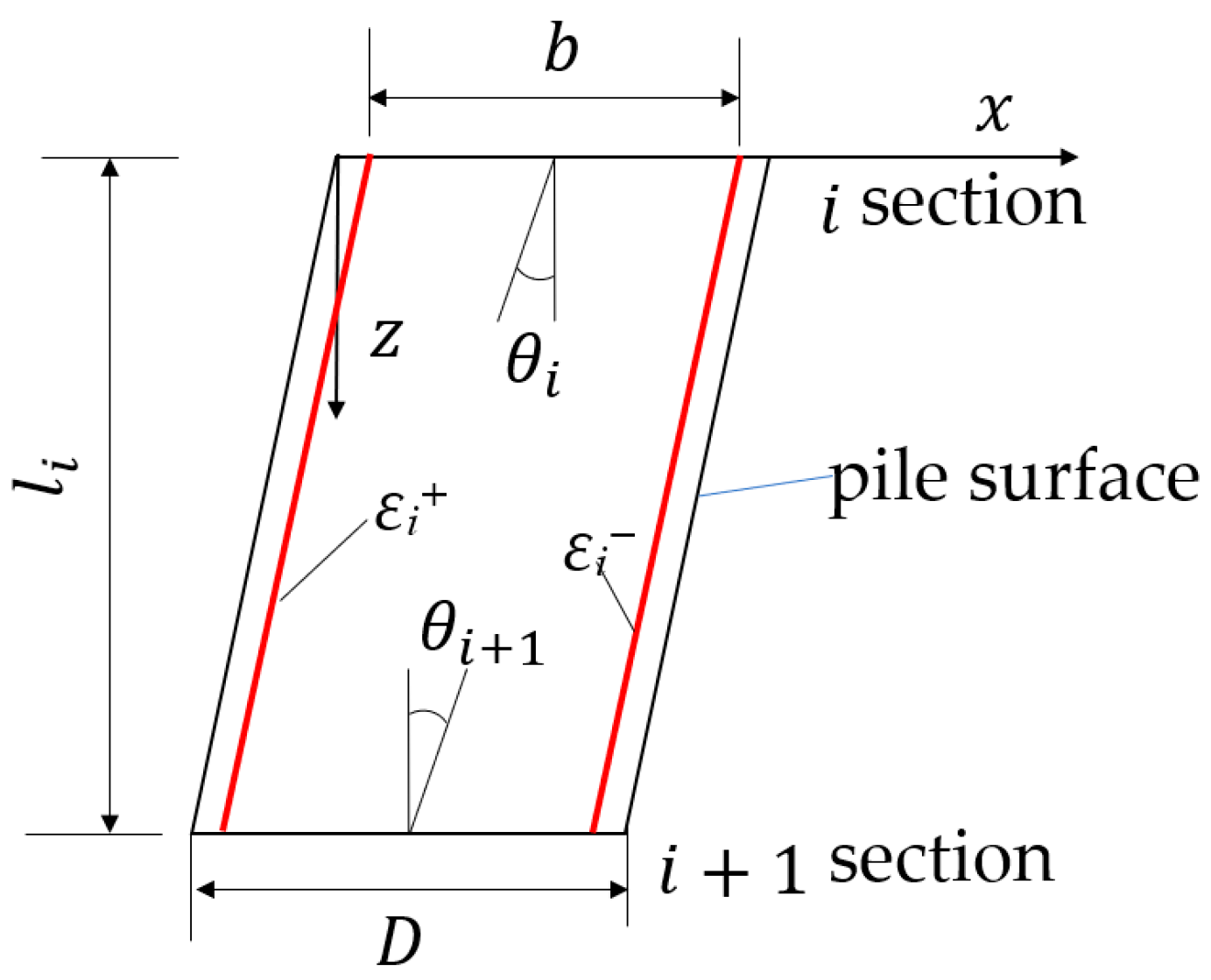
In the pile element deformation diagram: x denotes the horizontal direction; z denotes the vertical direction; li denotes the length of the pile element between sections i and i + 1; D denotes the pile diameter; θi denotes the rotation angle at section i; θi + 1 denotes the rotation angle at section i + 1.
In the scenario of lateral deformation, refer to Figure 7 for the schematic illustrating the deformation and rotation of the i element within the pile foundation. Denote Δ ε z = ( ε i + ε i ) as the strain differential between a given section at depth z and section i. This value can be determined by linearly interpolating the strain differential between sections i and i + 1. Therefore, we can express this relationship as follows:
Δ ε z = Δ ε i + ( Δ ε i + 1 + Δ ε i ) l i z
Substitute Equations (1) and (2) into the fundamental differential equation governing pile deflection to derive…
d 2 x d z 2 = M z E I
Substituting Equations (1) and (2) into the above equation yields…
d 2 x d z 2 = Δ ε z b = Δ ε i + ( Δ ε i + 1 Δ ε i ) z / l i b
The rotation angle and deformation expressions can be derived by conducting first- and second-order integrations on Equation (4).
θ ( z ) = d x d z = 1 b [ Δ ε i z + ( Δ ε i + 1 Δ ε i ) 2 l i z 2 ] + C
x z = 1 b Δ ε i z 2 2 + Δ ε i + 1 Δ ε i z 3 6 l i + C z + D
When z = 0
θ i = θ ( 0 ) = C
x i = x ( 0 ) = D
When z = li
θ i + 1 = θ i ( Δ ε i + 1 + Δ ε i ) 2 b l i
x i + 1 = x i + θ i l i ( Δ ε i + 1 + Δ ε i ) 6 b l i
Given the considerable depth of penetration of the test pile, negligible rotation angle and horizontal displacement are assumed at the pile tip. By systematically analyzing data from fiber Bragg grating strain gauges positioned at varying depths along the pile, ranging from near the base to the top, comprehensive insights into the rotational behavior and deformation characteristics of the entire pile structure can be derived.
Before testing, all instruments were carefully calibrated to ensure measurement reliability, with displacement calibration errors maintained within ±2%. During model preparation, drainage boundaries were established at the base and along the sidewalls of the container to minimize boundary effects. A static preload was applied under 1 g conditions and maintained until settlement reached equilibrium (60 min), after which centrifuge rotation was initiated. This procedure ensured complete system stabilization and enhanced the repeatability of the subsequent dynamic tests.

3. Results

3.1. Variation in the Horizontal Displacement at the Pile Top

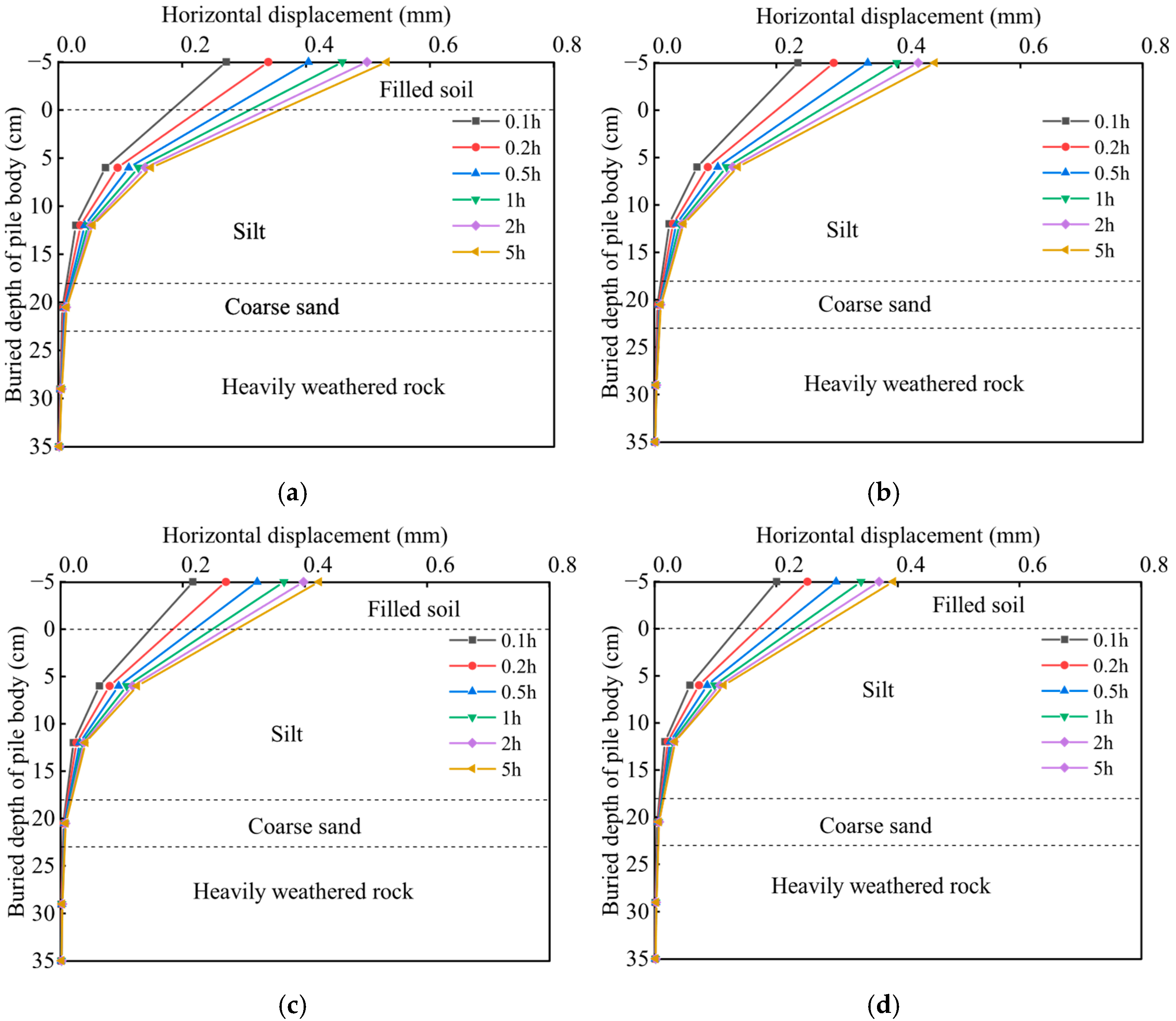
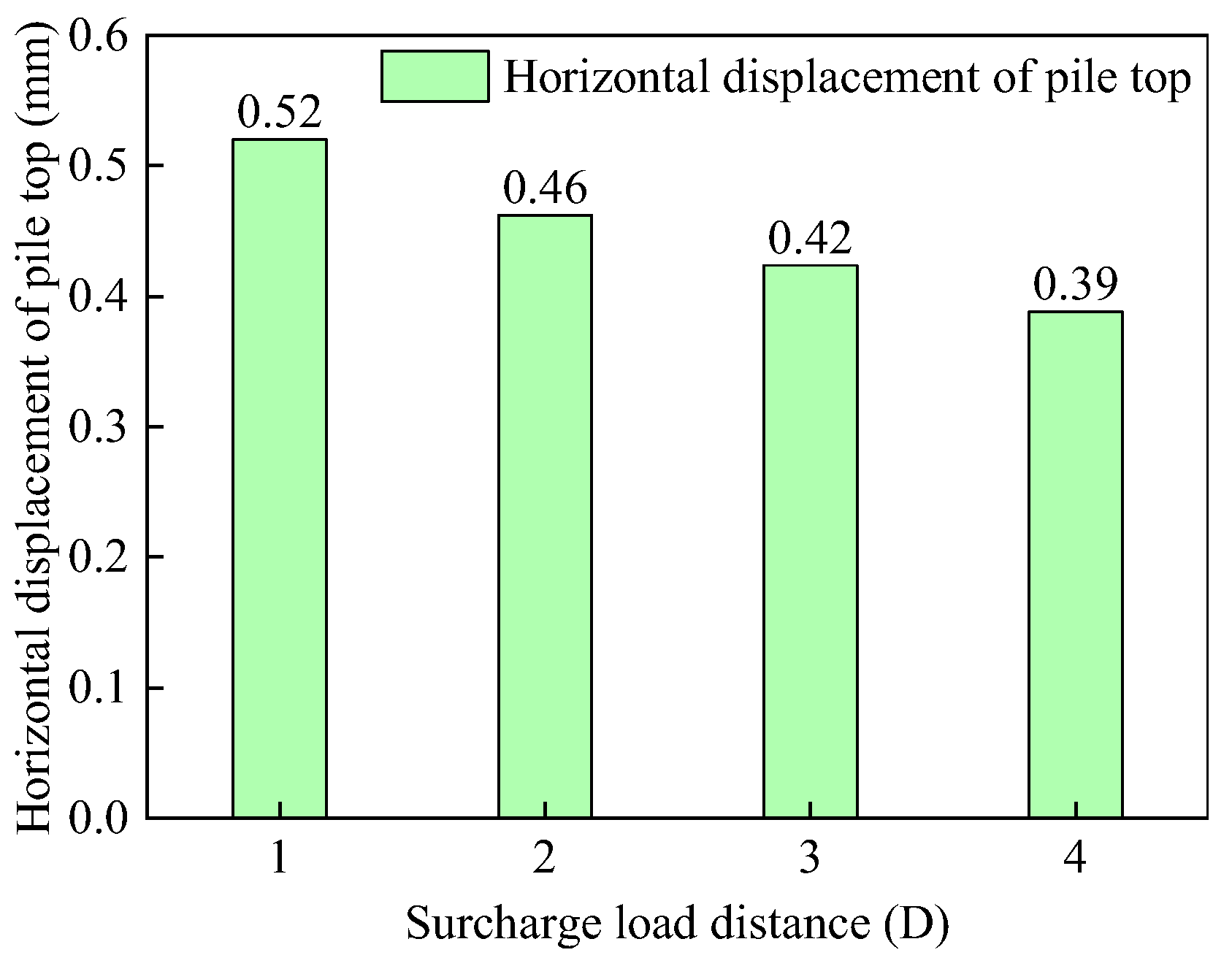
Figure 8, Figure 9 and Figure 10 illustrates the variation in the horizontal displacement at the pile top for surcharge load distances of 1D, 2D, 3D, and 4D.
Over time, the lateral displacement behavior of pile foundations remains consistent across various operational scenarios. Specifically, the lateral displacement at a given depth steadily increases over time, albeit at a diminishing rate, indicating a pronounced time-dependent effect. For instance, under the S = 2D condition, the lateral displacements at the pile’s top at 0.1, 0.2, 0.5, 1, 2, and 5 h are 0.24, 0.29, 0.35, 0.40, 0.43, and 0.46 mm, respectively. This trend underscores the ongoing increase in lateral displacement at the pile’s top with increasing consolidation time. Initially, rapid lateral displacement escalation occurs during consolidation, followed by a gradual decrease in the rate of increase. This phenomenon arises from the progressive dissipation of pore water over time, leading to increased effective stress, greater foundation soil stiffness, and stronger pile–soil interaction. Consequently, while the lateral displacement of the pile foundation continues to rise, the rate of increase diminishes.
As the surcharge distance increases, the lateral displacement behavior of pile foundations remains consistent across various operational scenarios. Specifically, lateral displacement decreases at a diminishing rate with greater surcharge distances. For instance, considering lateral displacement at the pile top, values are 0.52 mm, 0.46 mm, 0.42 mm, and 0.39 mm for surcharge distances of 1D, 2D, 3D, and 4D, respectively. Reductions in lateral displacement at the pile top between surcharge distances of 1-2D, 2-3D, and 3-4D are 0.015 mm, 0.009 mm, and 0.006 mm, respectively. This trend highlights the inverse relationship between the lateral displacement of pile foundations and the distance of the surcharge. Notably, smaller surcharge distances correspond to larger lateral displacements at the pile top, indicating heightened sensitivity of pile foundation deformation to proximal surcharges. This sensitivity arises from the lateral extrusion effect on the pile body, induced by soil displacement around the pile under surcharge, which, in turn, influences pile displacement. The significant association between surcharge distance and lateral displacement at the pile top fundamentally captures the spatial coupling effect within the soil–pile interaction system. In essence, the relative positions of surcharge application and pile foundation influence the stress redistribution in the soil and the static pile–soil interaction behavior.

3.2. Variation in Pile Shaft Bending Moment

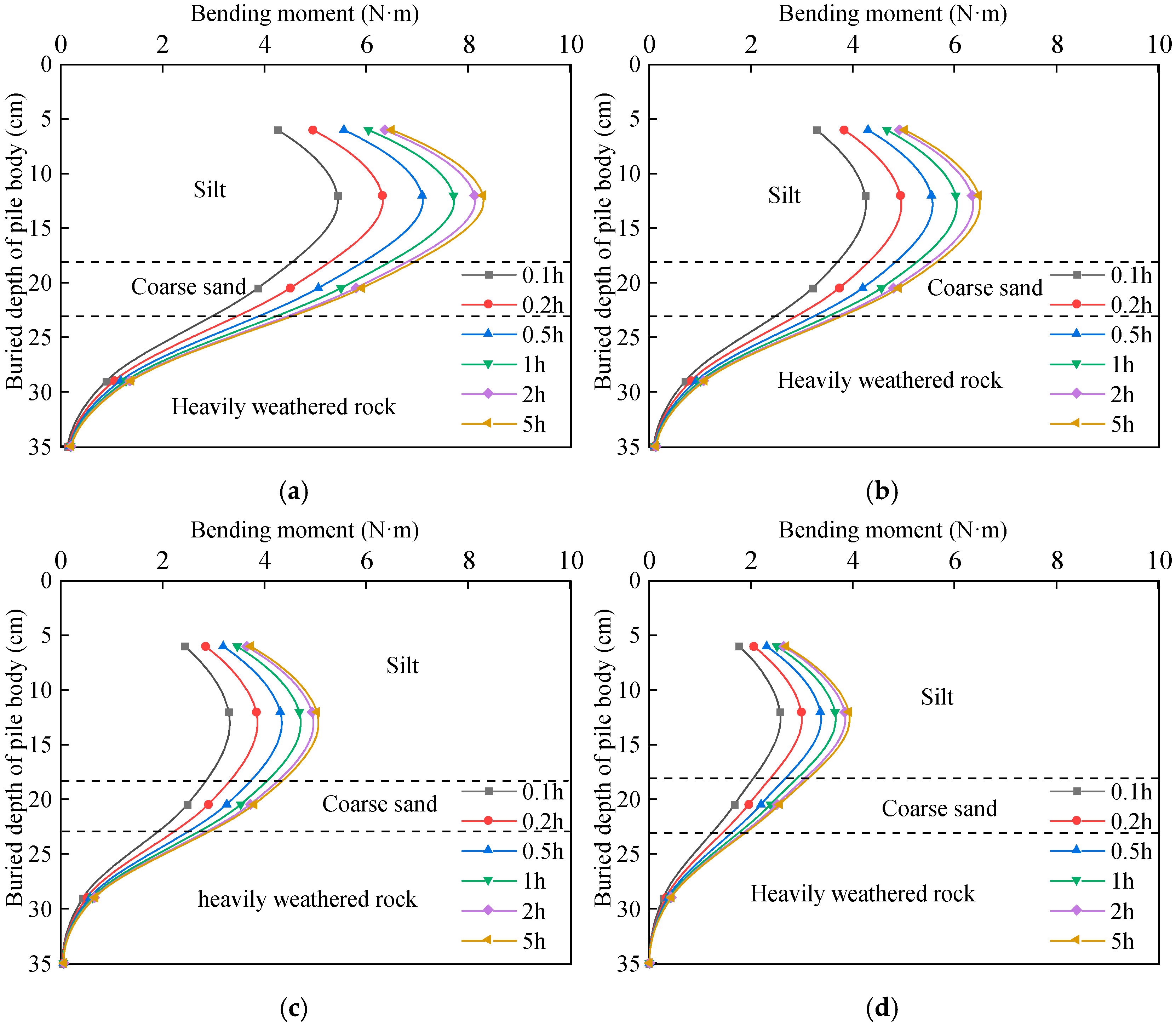
The bending moment curves of the pile are depicted in Figure 11 for surcharge load distances of 1D, 2D, 3D, and 4D.
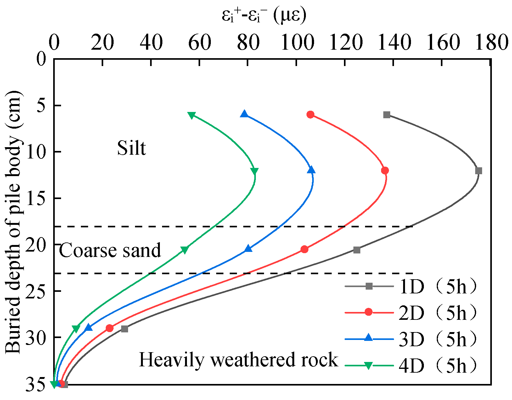
Figure 12 presents the differential strain measured by the front and rear side strain gauges along the pile under varying surcharge load distances. The results indicate that the strain difference increases with proximity to the applied surcharge, reflecting non-uniform load transfer along the pile shaft.
When a pile foundation supports lateral loads from surcharges, the load is distributed between the surrounding soil and the pile itself. This interaction results in lateral soil resistance acting on the pile. The remaining load is directly supported by the pile body, resulting in a significant increase in the bending moment acting on the pile.
Over time, the bending moments in pile foundations exhibit consistent patterns across various operational scenarios. Specifically, these bending moments increase steadily with time at equivalent depths, demonstrating pronounced time-dependent effects. The distribution pattern of bending moments along the depth of the pile body remains relatively stable as the duration of surcharge loading extends. Initially, the bending moments rise and subsequently decline with depth. Notably, the point of maximum bending moment consistently occurs at a burial depth of approximately 12 cm, with its magnitude moderately escalating as the duration of surcharge loading increases.
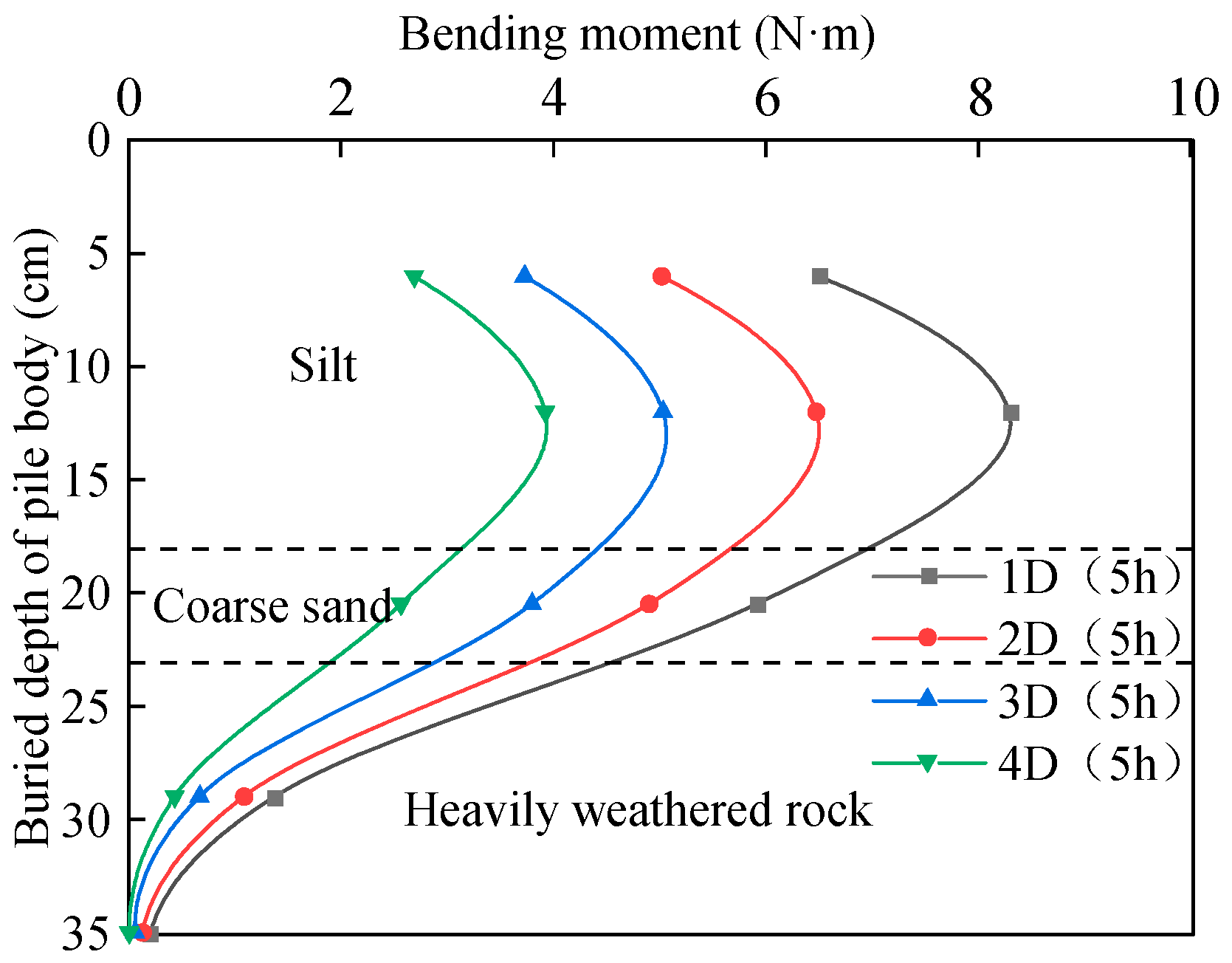
Figure 13 illustrates a distinctive single-peak variation in the bending moment of the pile along its length under varying surcharge distances. Specifically, the bending moment initially rises to a peak at 12 cm, then declines. This behavior is attributed to a surface silt layer that exhibits significant soil deformation under the surcharge load, leading to elevated bending moments. Upon penetration into a soil layer with greater strength, a subsequent reduction in the bending moment of the pile is observed.
As the surcharge distance increases, the bending moment at a fixed pile location decreases. For instance, at a pile embedment depth of 12 cm, the bending moments for surcharge distances of 1D, 2D, 3D, and 4D are 8.29, 6.47, 5.04, and 3.92 N·m, respectively. Beyond a surcharge distance of 4D, the reduction in pile bending moment diminishes. This suggests that for surcharge distances exceeding 4D, the surcharge’s impact on the pile foundation becomes less pronounced, resulting in a weaker influence. Initially, with shorter surcharge distances, the surcharge exerts a greater squeezing effect on the pile, thereby increasing bending moments. Conversely, longer surcharge distances allow for greater soil load dissipation during transmission, resulting in a substantial reduction in additional stress on the pile foundation and, consequently, a decrease in the pile’s bending moment.

3.3. Variation in Lateral Soil Resistance of Piles

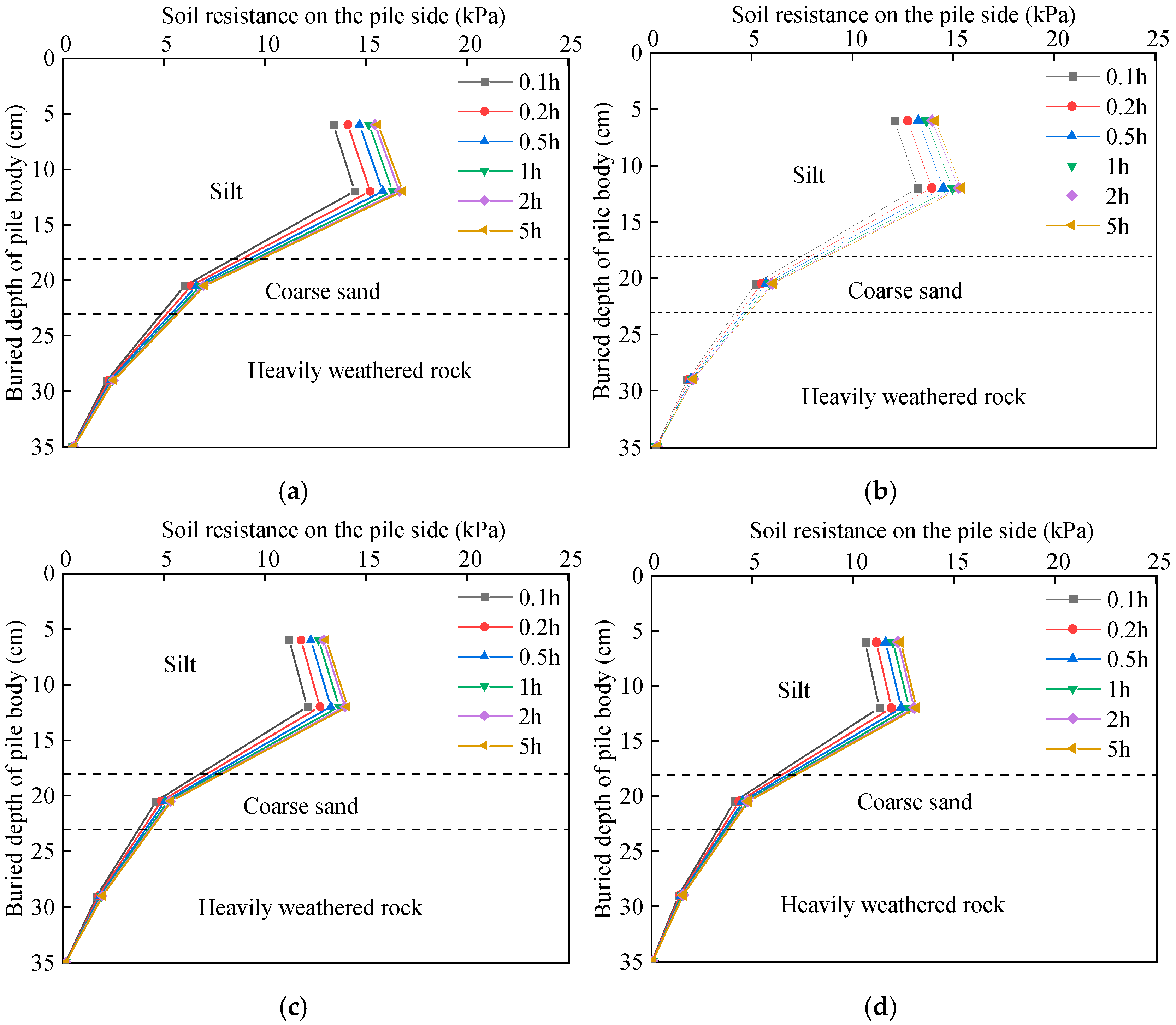
The lateral soil resistance curves of the pile are depicted in Figure 14 for surcharge distances of 1D, 2D, 3D, and 4D.
Over time, the lateral soil resistance laws for piles under various operational scenarios are consistent. Soil resistance at equivalent depths steadily increases, indicating pronounced time-dependent effects. The profile of lateral soil resistance along the pile depth remains unaltered, even with extended surcharge durations. In the vertical direction, soil resistance initially rises before declining. The depth at which maximum soil resistance occurs consistently lies at approximately 12 cm below the surface, with its intensity escalating as surcharge duration extends.
The lateral soil resistance of the pile exhibits consistent variation patterns with different surcharge distances, as depicted in Figure 15. This resistance generally increases from the top to the bottom of the pile, reaching a peak at 12 cm before decreasing. With an increase in surcharge distance, the lateral soil resistance diminishes at each specific position. For instance, at surcharge distances of 1D, 2D, 3D, and 4D, the maximum lateral soil resistance values are recorded as 16.83, 15.42, 14.09, and 13.15 kPa, respectively. The primary source of the lateral soil resistance on the pile stems from the interaction between the pile and the adjacent soil. When the surcharge distance is relatively short, the load concentrates around the pile, resulting in substantial soil deformation, increased horizontal soil pressure on the pile, and, consequently, significant lateral soil resistance. Conversely, as the surcharge distance increases, the load disperses more uniformly in the soil, resulting in a notable reduction in stress transmitted to the pile perimeter. This, in turn, minimizes soil disturbance around the pile, weakens the foundation pile’s response, and consequently decreases the lateral soil resistance at equivalent depths. As the surcharge distance expands, the impact of the surcharge on the soil surrounding the pile progressively diminishes.

4. Discussion

The centrifuge model tests demonstrate that both time-dependent and spatial attenuation effects dominate the mechanical behavior of pile foundations subjected to adjacent surcharge loading. The observed rapid increase and subsequent stabilization of displacement and internal forces are closely related to the consolidation characteristics of soft soil. During the early loading phase, excess pore water pressure dissipates rapidly, reducing effective stress and causing large lateral deformation of the soil mass around the pile. As consolidation progresses, the effective stress and shear strength of the soil increase, gradually stabilizing pile responses. This pattern aligns with the findings of Deng et al. [18] and Ding et al. [20], who reported similar temporal trends in field monitoring of surcharge-induced pile responses.
Along the pile depth, the bending moment exhibits a unimodal distribution, with a distinct peak located in the upper soft soil layer at an approximate depth of 10–14 cm. This depth corresponds to the transition between the soft clay and the underlying denser sand layer, where stress transfer between the pile and the surrounding soil reaches its maximum. The estimated peak depth is approximate due to the sparse sensor distribution and the use of linear interpolation between measurement points. In contrast, the lateral soil resistance follows an increase–decrease pattern, reaching its maximum in the middle soil layer. Similar phenomena were also reported by Wei et al. [23], who attributed such bending moment concentration to the stiffness contrast between strata, which induces localized bending and shear stress accumulation along the pile shaft.
The attenuation of pile response with increasing surcharge distance reveals that the lateral pressure induced by the embankment decays rapidly. At short surcharge distances (≤2D), the stress concentration near the pile produces pronounced soil movement and load transfer, significantly amplifying bending moments and displacements. When the surcharge exceeds 4D, the additional effect becomes small, suggesting an effective influence range of approximately 3–4 pile diameters. This conclusion is consistent with the numerical analyses of Gu et al. [24] and the experimental results of Yi and Liu [25], confirming that, beyond a critical distance, the surcharge load is primarily absorbed by the intervening soil mass.
From an engineering perspective, these findings underscore the importance of controlling the distance between embankment fills and existing bridge piles in areas with soft soil. For practical design, maintaining a minimum surcharge distance greater than four times the pile diameter can effectively mitigate adverse horizontal loads and bending moments. Furthermore, the results highlight the value of implementing soil improvement techniques to enhance subgrade stiffness and reduce pile deformation. Overall, this study bridges experimental evidence and field observations, contributing to a more comprehensive understanding of the mechanisms underlying surcharge–pile–soil interactions in soft foundations.

5. Conclusions

Based on centrifuge model tests investigating the influence of subgrade surcharge loading on adjacent bridge pile foundations, the following conclusions can be drawn:
(1)
The horizontal displacement, pile bending moment, and lateral soil resistance increase with time under sustained surcharge loading, showing pronounced time-dependent consolidation effects.
(2)
The horizontal displacement and bending moment both decrease with increasing surcharge distance, indicating an apparent spatial attenuation effect. The influence of surcharge loading becomes small but still measurable beyond approximately four times the diameter of the pile.
(3)
Along the pile depth, the bending moment exhibits a unimodal distribution with a peak in the soft upper soil layer. In contrast, lateral soil resistance follows an increase–decrease pattern, peaking in the middle layer.
(4)
The observed mechanical responses highlight that close surcharge loading can significantly compromise pile stability. Hence, maintaining adequate surcharge separation and improving the surrounding soil stiffness are essential for ensuring the long-term safety of bridge foundations adjacent to embankment fills.
These findings provide a refined experimental basis for the design and safety evaluation of pile foundations near embankments in soft soil environments, as the risk diminishes progressively. However, it is worth noting that this study represents a case-specific centrifuge investigation conducted under a single soil profile and loading condition. Therefore, a broader generalization of these results requires additional testing that considers different soil types, drainage conditions, and pile-spacing ratios (S/D) to validate their wider applicability.

Author Contributions

Conceptualization, Z.F. and S.Z.; methodology, J.L.; software, C.Z. (Chao Zhang); validation, C.Z. (Chao Zhang); formal analysis, S.Z.; investigation, J.W.; resources, J.L.; data curation, C.Z. (Chao Zhang); writing —original draft preparation, C.Z. (Chong Zhang); writing—review and editing, S.Z. and Z.F.; visualization, C.Z. (Chong Zhang); supervision, C.Z. (Chong Zhang); project administration, J.W.; funding acquisition, J.L. All authors have read and agreed to the published version of the manuscript.

Funding

This research received no external funding.

Data Availability Statement

The original contributions presented in this study are included in the article/supplementary material. Further inquiries can be directed to the corresponding author(s).

Conflicts of Interest

Authors Junyong Liu and Chao Zhang were employed by the company CCCC First Highway Consultants Co., Ltd. The remaining authors declare that the research was conducted in the absence of any commercial or financial relationships that could be construed as a potential conflict of interest.

References

  1. Li, Z. Study on the influence of adjacent surcharge loading on displacement of bridge pile foundations in soft soil. Rock Soil Mech. 2013, 34, 3594–3600. [Google Scholar]
  2. Yuan, B.; Chen, M.; Chen, W.; Luo, Q.; Li, H. Effect of pile-soil relative stiffness on deformation characteristics of the laterally loaded pile. Adv. Mater. Sci. Eng. 2022, 2022, 1–13. [Google Scholar] [CrossRef]
  3. Yuan, B.; Chen, W.; Zhao, J.; Li, L.; Liu, F.; Guo, Y.; Zhang, B. Addition of alkaline solutions and fibers for the reinforcement of kaolinite-containing granite residual soil. Appl. Clay Sci. 2022, 228, 106644. [Google Scholar] [CrossRef]
  4. Yuan, B.; Li, Z.; Chen, W.; Zhao, J.; Lv, J.; Song, J.; Cao, X. Influence of groundwater depth on pile-soil mechanical properties and fractal characteristics under cyclic loading. Fractal Fract. 2022, 6, 198. [Google Scholar] [CrossRef]
  5. Zhang, H.; Sun, K. Influence of surcharge load on the adjacent pile foundation in coastal floodplain. Insight-Civ. Eng. 2020, 3, 17–25. [Google Scholar] [CrossRef]
  6. Yi, S. Parametric study of passive piles subjected to adjacent surcharge load in extensively deep soft soil. Front. Mater. 2022, 9, 1080547. [Google Scholar] [CrossRef]
  7. Yi, S.; Liu, J. Field investigation of steel pipe pile under lateral loading in extensively soft soil. Front. Mater. 2022, 9, 480. [Google Scholar] [CrossRef]
  8. Zuo, L.; Cao, S.; Zhou, S.; Wu, J. Inversion of damage inducement of wharf pile foundation under heaped load based on parametric model. SN Appl. Sci. 2022, 4, 69. [Google Scholar] [CrossRef]
  9. Al-abboodi, I.; Sabbagh, T.T. Numerical modeling of passively loaded pile groups. Geotech. Geol. Eng. 2019, 37, 2747–2761. [Google Scholar] [CrossRef]
  10. Yu, Y.H.; Yan, B. Present Situation and Development Trend of Underground Space in Megacity in China. Chin. J. Undergr. Space Eng. 2021, 17, 1–7. [Google Scholar]
  11. Zhang, Y.; Guo, Y.; Zhang, Q. Experimental Study on the Horizontal Bearing Performance of Pile–Soil Composite Foundation Under Coupled Action of Active and Passive Loads. Buildings 2025, 15, 3184. [Google Scholar] [CrossRef]
  12. Li, T.; Yang, M. Investigation of Passive Pile Groups’ Responses Induced by Combined Surcharge-Induced and Excavation-Induced Horizontal Soil Loading. Buildings 2023, 13, 2775. [Google Scholar] [CrossRef]
  13. Li, T.; Yang, M.; Chen, X. Lateral Deformation Response of an Adjacent Passive Pile under the Combined Action of Surcharge Loading and Foundation Excavation. Sustainability 2023, 15, 13619. [Google Scholar] [CrossRef]
  14. Chen, H.; Feng, Z.; Wei, X.; Li, Y. Study on the Negative Skin Friction on Bridge Pile Foundations Induced by Backfilling in Karst Areas. Buildings 2025, 15, 3672. [Google Scholar] [CrossRef]
  15. Cheng, F.; Li, M.; Li, Q. Multi-Method Sensitivity Analysis of Influencing Factors on the Lateral Displacement of Retaining Piles in Asymmetric Excavations in Soft Soil Areas. Symmetry 2025, 17, 1525. [Google Scholar] [CrossRef]
  16. Cao, F.; Ye, C.; Wu, Z.; Zhao, Z.; Sun, H. Settlement Calculation of Semi-Rigid Pile Composite Foundation on Ultra-Soft Soil under Embankment Load. Buildings 2024, 14, 1954. [Google Scholar] [CrossRef]
  17. Dong, Y.; Feng, Z.; Feng, K.; Wen, J.; He, J. Effect of Road Embankment Overburden with Weak Interlayer on Bridge Pile Foundation and Its Treatment Methods. Chin. J. Undergr. Space Eng. 2020, 16, 1219–1229. [Google Scholar]
  18. Deng, H.; Dai, G.; Gong, W.; Zhu, Z. In situ experimental study of bearing characteristics of pile foundation under different balanced surcharges. Rock Soil Mech. 2015, 36, 3063–3070. [Google Scholar]
  19. Feng, T.; Gao, W.; Zhang, J.; He, Y. Effect of in-situ curing of joint composite foundations on pile-loaded adjacent pile foundations. J. Cent. South Univ. (Sci. Technol.) 2024, 55, 715–729. [Google Scholar]
  20. Ding, R. Field test study on pile foundation subjected to adjacent surcharge in deep-soft soil strata. J. Railw. Sci. Eng. 2015, 12, 291–296. [Google Scholar]
  21. Liu, Z. Field tests on negative skin friction of steel pipe piles in high backfilling soils. Chin. J. Geotech. Eng. 2015, 37, 337–342. [Google Scholar]
  22. Yuan, G.; Li, J. Centrifugal model tests on the influences of loads of a coal storage yard on the foundation and pile-based coal shed. Chin. J. Geotech. Eng. 2024, 46 (Suppl. S1), 197–201. [Google Scholar]
  23. Wei, L.; Zhang, K.; He, Q.; Zhang, C. Mechanical Response Analysis for an Active–Passive Pile Adjacent to Surcharge Load. Appl. Sci. 2023, 13, 4196. [Google Scholar] [CrossRef]
  24. Gu, M.; Cai, X.; Fu, Q.; Li, H.; Wang, X.; Mao, B. Numerical Analysis of Passive Piles under Surcharge Load in Extensively Deep Soft Soil. Buildings 2022, 12, 1988. [Google Scholar] [CrossRef]
  25. Li, H.; Liu, S.; Yan, X.; Gu, W.; Tong, L. Effect of loading sequence on lateral soil-pile interaction due to excavation. Comput. Geotech. 2021, 134, 104134. [Google Scholar] [CrossRef]
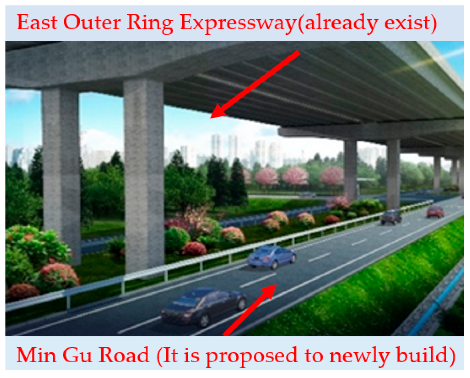
Figure 1. Schematic diagram of Mingu Road and East Outer Ring Expressway.
Buildings 15 04162 g001
Figure 2. TLJ-3 centrifuge model testing machine.
Buildings 15 04162 g002
Figure 3. Deep mixed columns model and plastic positioning hole.
Buildings 15 04162 g003
Figure 4. Working conditions schematic diagrams.
Buildings 15 04162 g004
Figure 5. Layout of the laser range finder (Jiangjing Intelligent Technology Co., Ltd., Suzhou, Jiangsu, China).
Buildings 15 04162 g005
Figure 6. Test element placement.
Buildings 15 04162 g006
Figure 7. Pile element deformation diagram.
Buildings 15 04162 g007
Figure 8. Horizontal displacement of the pile: (a) S = 1D, (b) S = 2D, (c) S = 3D, (d) S = 4D.
Buildings 15 04162 g008
Figure 9. The horizontal displacement of the pile body under different surcharge load distances.
Buildings 15 04162 g009
Figure 10. The horizontal displacement of the pile top under different surcharge load distances.
Buildings 15 04162 g010
Figure 11. Pile bending moment: (a) S = 1D, (b) S = 2D, (c) S = 3D, (d) S = 4D.
Buildings 15 04162 g011
Figure 12. Front and rear side strain gauge strain difference under different surcharge load distances.
Buildings 15 04162 g012
Figure 13. Pile bending moment under different surcharge load distances.
Buildings 15 04162 g013
Figure 14. Soil resistance on the pile side: (a) S = 1D, (b) S = 2D, (c) S = 3D, (d) S = 4D.
Buildings 15 04162 g014
Figure 15. Soil resistance of pile side under different surcharge load distances.
Buildings 15 04162 g015
Table 1. Performance parameters of the geotechnical centrifuge.
NameIndex
Maximum capacity60 g·t
Effective radius2.0 m
Degree of stability±0.1% F. S
Acceleration range10~200 g
The size of the model box700 × 360 × 500 mm
Table 2. Scaling laws of centrifugal model tests.
Physical QuantityDimensionSimilarity Constant
Acceleration aLT−2n
Force FMLT−21/n2
Water content w-1
Linear size lL1/n
Time t (consolidation)T−21/n2
Stress σFL−21
Density ρ FL−4T21
Note. The symbol M represents the bending moment.
Table 3. Comparison of flexural stiffness between model and prototype piles.
NameI/m4E/GPaEI/GN·m2n4EI/GN·m2Error/%
Prototype pile0.523015.45-8.7%
model pile1.55 × 10−8701.09 × 10−614.10
Error (%)” represents the relative difference between the model value and the prototype stiffness: E r r o r ( % ) = E I P r o t o t y p e n 4 E I m o d e l E I P r o t o t y p e × 100 % .
Table 4. Comparison of flexural stiffness between the model and prototype stirred pile piles.
NameI/m4E/GPaEI/GN·m2n4EI/GN·m2Error/%
Prototype deep mixed columns3.07 × 10−30.51.53 × 10−3-2.1%
Model deep mixed columns1.21 × 10−1021.23 × 10−101.56 × 10⁻³
Table 5. Mechanical parameters of soil in centrifugal test.
StratumNameWater ContentUnit Weight
/kN/m3
Compression Modulus/MPaFriction Angle/°Cohesion/kPa
Soft soilPrototype-16.62.04.55.8
Coarse sandPrototype-18.85.021.02.0
Heavily weathered rockPrototype-22.040.825.025.1
Filled soilPrototype-20.16.216.122.0
Soft soilModel45.1%16.52.14.65.8
Coarse sandModel5.3%18.65.121.52.1
Heavily weathered rockModel10.7%21.742.125.225.3
Filled soilModel13.5%20.46.116.322.2
Disclaimer/Publisher’s Note: The statements, opinions and data contained in all publications are solely those of the individual author(s) and contributor(s) and not of MDPI and/or the editor(s). MDPI and/or the editor(s) disclaim responsibility for any injury to people or property resulting from any ideas, methods, instructions or products referred to in the content.