Abstract
In the saline, cold, and arid regions of Western China, the adhesive performance at the carbon fiber-reinforced polymer (CFRP)–concrete interface critically affects the long-term reliability of CFRP-strengthened structures. Replacing the organic epoxy resin (EP) with inorganic magnesium phosphate cement (MPC) has been proposed as an alternative. However, comparative studies on the deterioration of MPC- and EP-bonded CFRP–concrete under sulfate freeze–thaw cycles are limited. This study employed double-shear tests to systematically compare the failure modes, ductility, and bond performance of the CFRP–concrete interface bonded with MPC and EP after 25, 50, and 75 sulfate freeze–thaw cycles. The results indicate that, as the number of cycles increased, MPC-bonded specimens exhibited progressive interfacial peeling, whereas EP-bonded specimens underwent abrupt brittle fracture. At 0, 25, 50, and 75 cycles, the peak strains of MPC specimens exceeded those of EP specimens by 9.28%, 10.13%, 5.99%, and 0.86%, respectively, indicating greater ductility. Bond performance declined markedly for both groups as cycles increased, with MPC specimens showing greater deterioration. After 75 cycles, compared with EP-bonded specimens, MPC-bonded specimens showed a 16.56% lower interfacial load capacity, a 21.53% reduction in peak bond stress, and a 6.03% shorter effective bond length. This systematic comparison of MPC- and EP-bonded CFRP–concrete under sulfate freeze–thaw exposure provides guidance for adhesive selection and strengthening practices in saline, cold, and arid regions.
1. Introduction
Long-term service reduces the load-bearing capacity of concrete structures. To extend service life, carbon fiber-reinforced polymer (CFRP) strengthening has been demonstrated as an economical and reliable means [1,2,3,4]. Reliable bond performance at the CFRP–concrete interface is critical to the effectiveness of these interventions [5], and the choice of adhesive directly influences long-term durability. Furthermore, Western China experiences cold, arid winters [6] and widespread saline soils and salt-lake landforms [7,8], where sulfate concentrations can be five to ten times higher than in marine environments. Under the significant sulfate freeze–thaw cycling effect locally, adhesive performance is severely compromised [9]. Cyclic frost heave stresses generated during freeze–thaw produce microcracks within the adhesive and at the interface [9]. Concurrently, high concentration sulfate solutions induce interfacial loosening and softening via mechanisms such as expansive pressure from crystallization [10]. The coupled and cumulative action of these physical and chemical mechanisms commonly yields synergistic deterioration of the CFRP–concrete interface that surpasses the effect of any single factor, thereby jeopardizing the long-term safety of the strengthened structure [11]. Accordingly, selecting an appropriate bonding system is essential for durable CFRP–concrete strengthening.
Epoxy resin (EP), a widely used organic adhesive, polymerizes through reactions of its epoxy groups to form a rigid, highly cross-linked network that provides high initial bond strength [12]. Its low viscosity and high fluidity enhance substrate wetting and filling of interfacial defects, facilitating on-site application [13,14]. Consequently, EP has become the predominant adhesive for bonding CFRP to concrete.
However, studies indicate that EP’s epoxy groups can react with biologically reactive groups during handling and curing, posing occupational health risks [15]. Moreover, the highly cross-linked EP matrix, while imparting high strength, exhibits limited fracture toughness [16]. These limitations constrain the use of EP in certain service environments.
Magnesium phosphate cement (MPC) is produced by an acid–base neutralization reaction between dead-burned magnesia and phosphate, with retarders and mineral admixtures. It exhibits rapid early strength development and excellent corrosion resistance [17,18,19,20,21]. MPC provides an alternative bonding approach for CFRP–concrete systems. Studies show that, when used as an adhesive, MPC significantly improves the flexural and shear capacity of concrete specimens and enhances structural ductility [22,23,24]. This rapid early strength promotes prompt bond formation with the concrete substrate. Li et al. [25] replaced organic adhesives with MPC in CFRP-to-concrete column tests and reported that MPC did not change the fundamental failure mode or stress–strain response but increased ultimate strength and improved ductility. However, MPC’s rapid hydration generates substantial quantities of amorphous products that are thermodynamically unstable and introduce numerous pore defects, thereby reducing material density [26]. The addition of setting retarders effectively mitigates these issues. Common retarders for MPC include borax, boric acid, and sodium tripolyphosphate. In addition, MPC exhibits a relatively high fraction of ionic and covalent bonding, and the directional character of these bonds increases its intrinsic brittleness [27]. Nonetheless, studies indicate that optimizing mix proportions can substantially improve MPC’s toughness under freeze–thaw cycling [28].
Researchers have investigated MPC behavior under various salt–freeze–thaw coupling conditions and shown that MPC-based materials exhibit resistance to combined deterioration induced by freeze–thaw in sodium sulfate and magnesium sulfate solutions [29]. Degradation during immersion depends on the salt species. Deterioration in sodium sulfate solutions is substantially greater than in sodium chloride solutions [30]. Li et al. [31] analyzed hydration products after long-term immersion and found that a 5% sodium sulfate solution caused the greatest loss of hydration products. Yang et al. [32] reported that, after 50 sulfate freeze–thaw cycles, MPC mortar experienced substantially lower mass loss and retained higher strength than ordinary cement mortar. Shan et al. [33] conducted sulfate freeze–thaw tests on MPC-based materials from coastal regions and found that deterioration primarily results from internal ice expansion and salt crystallization pressures within the matrix. Furthermore, incorporation of silica fume promotes matrix densification and thereby mitigates damage caused by sulfate freeze–thaw cycling. Moreover, when applied as a protective surface coating, MPC demonstrates good salt resistance even in single-sulfate environments [34,35,36].
Existing comparative studies of EP and MPC have primarily examined modified MPC-based materials—such as potassium magnesium phosphate cement (MKPC) and high-performance magnesium phosphate cement (HMPC). Although these variants contain additional admixtures, they retain the principal properties of MPC. Kai [37] compared CFRP-confined columns bonded with HMPC and EP and reported that HMPC bonding materials enhance confined load capacity and deformability relative to EP. Xue [38] compared CFRP–concrete systems bonded with MKPC and EP and found that MKPC provides superior wettability to CFRP and higher bond strength than EP.
Most studies of CFRP–concrete interfacial bond behavior under sulfate freeze–thaw cycles have employed EP as the adhesive. These investigations indicate that sulfate freeze–thaw cycles markedly degrade the EP and CFRP–concrete interface. After 100 coupled cycles, the failure load decreased by 37.7%, accompanied by reductions in interface strain and peak shear stress [39]. However, no study to date has directly compared the interfacial bond behavior of MPC-bonded and EP-bonded CFRP–concrete systems under coupled sulfate freeze–thaw conditions.
EP-based CFRP–concrete bonding systems emit volatile organic compounds that pose occupational health risks and exhibit low fracture toughness. MPC, an inorganic adhesive with rapid setting and high compatibility with concrete, provides an alternative adhesive for CFRP–concrete bonding. However, existing research on bond degradation under coupled sulfate freeze–thaw cycles has primarily focused on epoxy adhesives. The bond performance evolution of MPC-bonded CFRP–concrete remains unclear.
This study systematically compares the failure modes, ductility, and bond degradation of CFRP–concrete specimens bonded with MPC and EP under coupled sulfate freeze–thaw cycles through a series of mechanical tests. Double shear tests were conducted to develop predictive models for effective bond length and a local bond–slip constitutive relation for MPC- and EP-bonded CFRP–concrete subjected to sulfate freeze–thaw exposure. The results elucidate damage and deterioration mechanisms of MPC- and EP-bonded CFRP–concrete interfaces under sulfate freeze–thaw conditions and provide a theoretical basis for CFRP strengthening practice in the saline, cold, and arid regions of Western China.
2. Materials and Methods
2.1. Experimental Materials
2.1.1. MPC
The MPC used in this study was prepared by proportionally blending dead-burned magnesia (M), borax (B), potassium dihydrogen phosphate (P), silica fume (SF), fly ash (FA), and water (W). The M had a density of 3.3 g/cm3, a specific surface area of 235 m2/kg, and a light-brown appearance (component parameters are in Table 1).

Table 1.
M-component parameters (%).
P was selected as an analytical-grade white crystalline powder produced by Fuchen (Tianjin, China) Chemical Reagent Co., Ltd., with a relative molecular mass of 136.09, and purity exceeds 99.5%. B is a white crystalline powder with purity ≥ 99.5%. FA and SF were supplied by Borun Casting Materials Co., Ltd. (Changge, China). Tap water was used for mixing. Specific MPC mix proportions are given in Table 2.

Table 2.
Mix proportions of MPC (/g).
For specimen preparation, P, B, FA, and SF were weighed per the prescribed proportions and dry-mixed. Then water was added and stirred. MgO was subsequently introduced, and the mixture was high-speed-mixed for 90 s. The slurry was cast into 40 mm × 40 mm × 160 mm molds (Figure 1), compacted on a vibration table for 60 s, cured in air, and demolded. The flowability of the freshly mixed MPC paste, measured according to GB/T 8077-2023 [40], was 205 ± 2 mm.
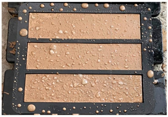
Figure 1.
MPC paste compacted in the mold.
After air curing, specimens were examined by scanning electron microscopy (SEM) (Figure 2). SEM images show unreacted free MgO particles uniformly distributed on the cured MPC surface. Unreacted MgO appears as small, irregular, angular or plate-like grains, typically located at the margins of or within the interstices of spherically shaped fly ash particles [41]. Fly ash particles (about 30–40 μm) and silica fume particles (about 2 μm) combine with MgO reaction products to fill surface pores and enhance integrity. At higher magnification, surface cavities attributable to gas channels formed during the exothermic early hydration of MPC are visible. Overall, the cured MPC surface is relatively dense but retains some porosity. This pore structure facilitates the formation of continuous defect pathways in the interfacial region, thereby enhancing the ingress of sulfate solutions.
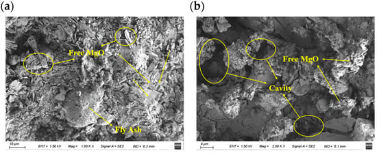
Figure 2.
SEM images of MPC after air curing: (a) ×1000; (b) ×2000.
2.1.2. EP
The two-component EP was supplied by Kaben Technology Group Co., Ltd. (Tianjin, China). Components A and B were mixed at a mass ratio of 2:1 and stirred until homogeneous. Testing showed that the tensile strength of the epoxy resin is ≥39 MPa, the tensile modulus is ≥2400 MPa, the elongation is ≥1.5%, and the heat deflection temperature is >65 °C. Under the conditions of (23 ± 2) °C and (60 ± 10)% relative humidity, the viscosity of component A is approximately 10,000 mPa·s, while that of component B is 50,000–80,000 mPa·s. The working time at 25 °C is 40 min.
2.1.3. Concrete
Portland cement (C) used in the tests was P.O. 42.5 ordinary Portland cement. Sand (S) was prepared by blending natural medium sand (fineness modulus 2.54) with manufactured sand (particle size 1.18–4.75 mm) at a mass ratio of 1:2. Coarse aggregate (G) was crushed stone with a maximum particle size of 31.5 mm. Municipal tap water was used for mixing. A polycarboxylate-based superplasticizer providing approximately 25% water reduction served as the water-reducing admixture. Concrete mix proportions are given in Table 3.

Table 3.
Concrete mix proportions (kg/m3).
2.1.4. Salt Solution
The saline corrosion solution was a sodium sulfate (Na2SO4) solution with a mass fraction of 5%, prepared from analytical-grade anhydrous Na2SO4 (Damao Chemical Reagent Factory, at least 99% Na2SO4, less than 0.005% insoluble matter). The required mass of salt was dissolved in distilled water and stirred with a glass rod until fully dissolved.
2.1.5. CFRP
Carbon fiber fabric was supplied by Kaben Technology Group Co., Ltd. Technical specifications are listed in Table 4.

Table 4.
Performance parameters of CFRP sheet.
2.2. Experimental Design
2.2.1. Sulfate Freeze–Thaw Cycle
Pronounced sulfate freeze–thaw cycling occurs in the northwestern cold-arid saline region. To evaluate its effect on the bond deterioration mechanisms of CFRP–concrete assemblies incorporating different adhesives, specimens were exposed to a controlled sulfate freeze–thaw degradation protocol. The sulfate freeze–thaw test was performed in accordance with DL/T 5150-2017 [42]. CFRP–concrete specimens were immersed in a Na2SO4 solution with a mass fraction of 5% and subjected to rapid freeze–thaw cycles, each lasting 3 h. The temperature at the specimen center was cycled between −18 ± 2 °C and 5 ± 2 °C. Test cycles were planned for 25, 50, 75, and 100 repetitions. The cooling stage from 5 °C to −18 °C lasts 60 min, followed by an isothermal hold at −18 °C for 60 min. The heating stage from −18 °C back to 5 °C then lasts 60 min. Together, these stages constitute one cycle (Figure 3). However, because the C40 concrete (The strength grade of concrete) exhibited localized freeze damage and interfacial delamination after 100 cycles, which precluded the double shear test, the maximum number of cycles was limited to 75. Three groups of specimens were prepared, each comprising eight specimens. In addition, six CFRP–concrete specimens stored at room temperature served as controls, arranged as two groups of three specimens. To avoid changes in solution concentration during exposure, the immersion solution was replaced after every cycle. Specimens were placed in rubber sample boxes and immersed in a prepared 5% Na2SO4 solution to a level approximately 5 mm above the specimen end faces. The solution was thoroughly stirred with a glass rod prior to addition to ensure homogeneity. To account for concentration changes during cycling, the solution was replaced after each cycle.
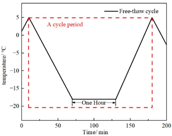
Figure 3.
Temperature control profile for the cycle.
Specimen identification codes are listed in Table 5. M0 denotes the room-temperature control group of MPC-CFRP–concrete specimens (0 sulfate freeze–thaw cycle). MD25, MD50, and MD75 denote MPC-bonded specimens subjected to 25, 50, and 75 cycles, respectively. The EP group follows the same naming convention.

Table 5.
Specimen designation.
2.2.2. Compressive Strength Test
Compressive strength test followed GB/T 50081-2019 [43]. Nonstandard concrete prisms (100 mm × 100 mm × 200 mm) were cast, subjected to the sulfate freeze–thaw deterioration protocol described above. Specimens were tested after 25, 50, and 75 cycles. Tests were conducted on a TYE-2000E hydraulic press (Jianyi Instrument Machinery Co., Ltd. (Wuxi, China)) under displacement control at a rate of 0.5 mm/min.
2.2.3. Double Shear Test
- 1.
- Preparation of Double Shear Specimens
The specimen preparation procedure is summarized in Figure 4.
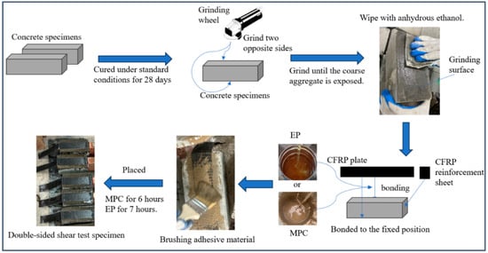
Figure 4.
Fabrication process of double shear specimens.
- (1)
- Cast concrete prisms measuring 100 mm × 100 mm × 200 mm and cure under standard conditions for 28 days.
- (2)
- After casting, two opposite faces of each concrete specimen were prepared for CFRP bonding. Surfaces were ground with an angle grinder until the coarse aggregate was exposed, and surface roughness was measured with a profilometer to confirm a Ra of 30–50 μm. Prior to bonding, surfaces were cleaned with anhydrous ethanol and conditioned at 23 ± 2 °C and 60 ± 10% relative humidity for at least 24 h to ensure substrate dryness.
- (3)
- Clean the ground surfaces with anhydrous ethanol and mark the CFRP bonding areas.
- (4)
- Bond CFRP using either EP or MPC to evaluate adhesive effects on shear performance. The design bond length is 200 mm [44]. For EP bonding, mix components A and B in a 2:1 ratio, stir thoroughly, and apply to the bonding area. After approximately 7 h, reapply the epoxy, position the CFRP, roll to consolidate, reapply epoxy, and cure for 48 h. Repeat the same procedure on the opposite face. For MPC bonding, apply freshly mixed MPC to the bonding area, position the CFRP, roll to consolidate, apply an additional MPC layer over the CFRP, allow 6 h set time, and then repeat on the other face. The selection of 48 h curing for EP and 6 h hardening for MPC in this study is based on their markedly different curing behaviors. EP undergoes a relatively slow polymerization reaction, and a 48 h cure ensures attainment of a stable strength plateau. By contrast, MPC hardens via a rapid acid–base reaction and develops load-bearing early strength within 6 h, reflecting its advantage of fast setting and early strength gain. Spacers were placed on both sides of the concrete bonding area to control bond-layer thickness. After adhesive application, the layer was leveled with a trowel and the CFRP was rolled to ensure full contact. Spacers were removed to produce a uniform bond layer, and thickness was measured at the specimen side with a vernier caliper. The mean controlled thickness was 1.5 ± 0.5 mm for EP and 2.5 ± 0.5 mm for MPC. The thicker MPC layer, due to incorporated aggregate, was trimmed by sanding [45,46].
- (5)
- To mitigate stress concentration at the CFRP ends during loading, bond a 50 mm × 50 mm patch of carbon fiber fabric to each CFRP end using the corresponding adhesive.
Strain gauges were mounted along the CFRP centerline and numbered 1–9 from the loading end toward the free end. Strain data were acquired using a JM5951 data acquisition system. After specimen preparation, gauge locations were cleaned with anhydrous ethanol, gauges were bonded to the CFRP with adhesive, and electrical junctions were sealed with Kafte sealant to prevent short circuits. The specimen and gauge layout are shown in Figure 5.
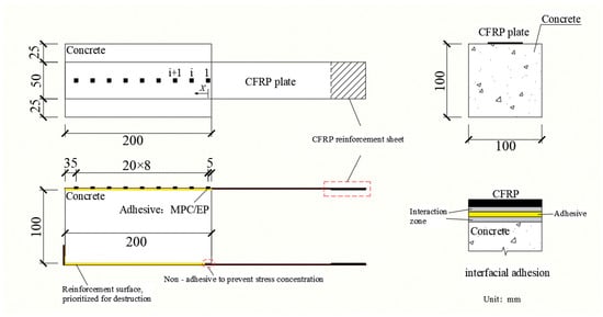
Figure 5.
Strain gauge layout and schematic of the double-shear specimen.
- 2.
- Test Method
After deterioration, specimens underwent a double shear test using a computer-controlled electro-hydraulic servo universal testing machine (Figure 6). Loading was displacement-controlled at 0.2 mm/min. An L-shaped stiffener was attached to one side of the CFRP to prevent failure of the non-tested face. During testing, the interface failure mode, interfacial load capacity, and tensile-direction strain distribution of the CFRP were recorded.
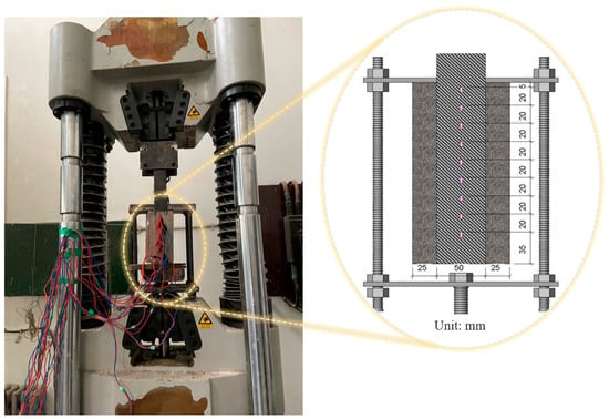
Figure 6.
Loading fixture and loading schematic for double shear specimens.
3. Results and Analysis
3.1. Compressive Strength
The compressive strength of concrete specimens subjected to different numbers of sulfate freeze–thaw cycles is presented in Figure 7. Strength initially increased slightly and then declined as the number of cycles increased. After 25 cycles, compressive strength increased by 0.72% relative to the initial value. After 50 and 75 cycles, compressive strength decreased by 0.48% and 10.84%, respectively, relative to the initial value. The error of the compressive strength results for specimens after cycling ranged from 0.21 to 0.83. The early increase is attributed to penetration of sulfate ions into the pore structure and partial pore filling, which densifies the matrix and marginally enhances strength [47]. With continued cycling, sulfate crystallization and freeze–thaw action generates expansive stresses that damage the pore structure and generate cracking. Consequently, deterioration accelerates with increasing cycle number [48].
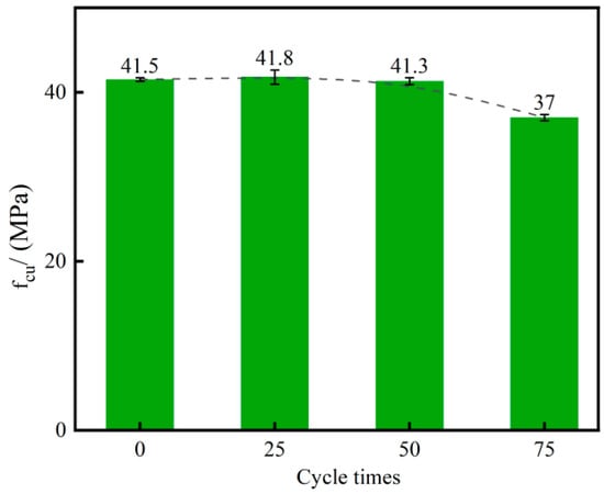
Figure 7.
Compressive strength of concrete after various numbers of sulfate freeze–thaw cycles.
3.2. Interface Failure Modes
The CFRP–concrete interface should be considered a multilayer interaction region rather than a single, well-defined interface. It comprises the CFRP layer, the CFRP–adhesive interaction zone, the adhesive layer, the adhesive–substrate interaction zone, and the concrete substrate [49] (Figure 8). Five principal failure modes were observed in the CFRP–concrete double shear specimens, which are CFRP rupture, CFRP–adhesive debonding, adhesive layer failure, adhesive–concrete delamination, and shear failure of the concrete substrate [50].
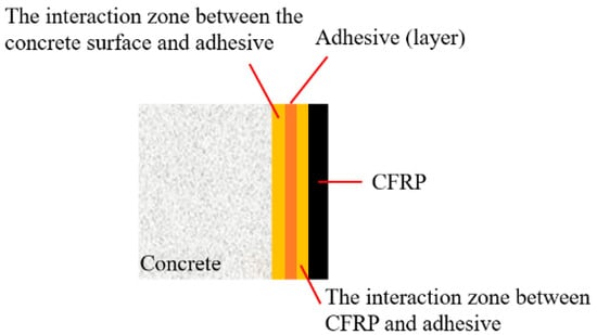
Figure 8.
Bonding zones at the CFRP–concrete interface.
- (1)
- EP-bonded specimens
The failure modes for EP-bonded specimens are shown in Figure 9. Uncycled specimens failed predominantly by shear of the concrete substrate, evidenced by abundant concrete and aggregate adhering to the CFRP (Figure 9a). After 25 cycles, failure shifted primarily to delamination between the adhesive and the concrete. Fracture surfaces were smooth and little concrete remained on the CFRP (Figure 9b). After 50 and 75 cycles, failures were mixed, involving both substrate shear and adhesive–concrete delamination (Figure 9c,d). In all cases, only small amounts of concrete adhered to the CFRP, although substantial local loss occurred (notably at the lower-right corner) due to stress concentration, concrete loss after 75 cycles exceeded that after 50 cycles.
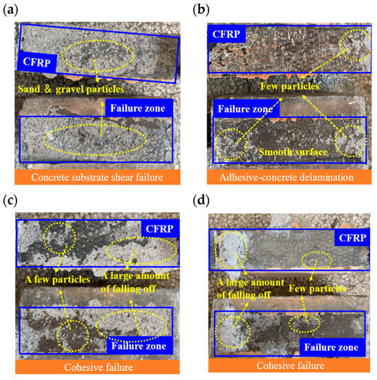
Figure 9.
Interface failure modes under EP adhesive: (a) E0; (b) ED25; (c) ED50; (d) ED75.
- (2)
- MPC-bonded specimens
The MPC-bonded specimens are illustrated in Figure 10. Uncycled MPC specimens failed by substrate shear, with many small concrete particles adhering to the fracture surface (Figure 10a). After 25, 50, and 75 cycles, failures were dominated by adhesive–concrete delamination, producing smooth fracture surfaces with minimal concrete particle retention (Figure 10b–d).
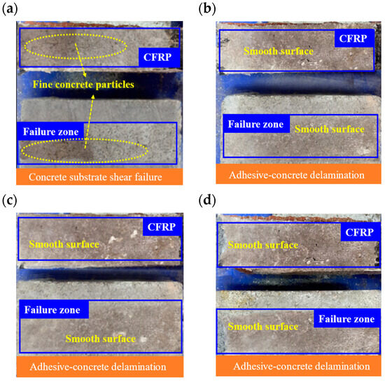
Figure 10.
Interface failure modes under MPC adhesive: (a) M0; (b) MD25; (c) MD50; (d) MD75.
These observations indicate that damage concentrates at the adhesive–substrate interface and predominantly affects the concrete substrate, consistent with that region’s relatively low interfacial strength [51]. In this study, the CFRP exhibited high tensile capacity, and the reinforcement strips at the clamp ends remained intact. Consequently, sulfate freeze–thaw cycles caused greater damage at the bond interface than within the concrete interior. With increasing cycles, internal concrete strength declined and edge spalling became more pronounced. Sulfate freeze–thaw cycling promotes crack propagation and bond failure through the combined effects of freezing-induced expansion and sulfate crystallization within transition-zone pores [52]. The MPC system, owing to rapid setting and limited penetration depth, tends to coat the CFRP surface and can form erosion channels at the interface [53]. This effect intensified with cycling and led to predominant delamination after 50 cycles. By contrast, the epoxy system penetrates the substrate more effectively, facilitating stress transfer into the concrete and improving resistance to pure delamination, although cumulative damage can still produce mixed-mode failure [54].
3.3. Interfacial Load Capacity
The axial tensile force at failure in the double shear specimen defines the interfacial load capacity . To quantify this capacity, parameters such as , (relative value of ), , and were introduced. referred to average bond strength, which was calculated by dividing the interfacial load capacity by the bonded area, shows a linear correlation with the square root of concrete compressive strength [55]. Relative bond strength was obtained by normalizing this bond strength by the square root of the pre-cycling concrete compressive strength. Normalization reduces the influence of variability in concrete strength and makes relative changes a more accurate indicator of environmental degradation effects on interfacial bond performance. In addition, represents the maximum strain recorded at the first measurement point near the loading end was used as an indicator of local deformation.
Interface shear-bonding results are presented in Table 6. In ambient (unexposed) conditions, the peak loads of MPC- and EP-bonded CFRP double shear specimens were 6.50 and 6.81 kN, respectively, indicating similar initial bond performance. With increasing sulfate freeze–thaw cycles, the interfacial load capacity of both EP and MPC groups progressively deteriorated. For the MPC group, bearing capacity decreased by 5.35% after 25 cycles and by 17.70% and 52.89% after 50 and 75 cycles, respectively, relative to the control. For the EP group, bearing capacity decreased by only 0.53% after 25 cycles, but fell by 13.47% and 42.07% after 50 and 75 cycles, respectively, indicating an accelerated deterioration rate at higher cycle counts.

Table 6.
Experimental results of interfacial shear-bond performance.
Comparing adhesives, EP-bonded specimens exhibited higher residual shear capacity than MPC-bonded specimens despite broadly similar degradation trends. This difference is attributed to the limited penetration of MPC into the CFRP–concrete interface, which favors the formation of erosion channels and easier ingress of salt solution. Under repeated sulfate freeze–thaw cycles, this accelerates bond deterioration [53].
Combining interface performance with concrete compressive strength data shows that, after 50 sulfate freeze–thaw cycles, the reduction in interfacial load capacity already exceeds the compressive strength reduction in concrete specimens observed after 75 cycles. This indicates that, under the coupled action of sulfate exposure and freeze–thaw cycling, service life is governed primarily by the durability of the bonded interface rather than by bulk concrete strength.
3.4. Strain Distribution
Measured curves were consistent across specimens. Therefore, Group M0 is presented as representative (Figure 11). Prior to failure, load–strain responses at all gauge locations were linear. When the applied load was below 6 kN, bond stresses were concentrated near the loading end (gauges 1–5). Once the load exceeded 6 kN, the bond stress gradually shifted toward the free end until failure occurred. The relatively low strain values at the free end at failure indicate limited interfacial load capacity in that region and rapid debonding between the CFRP and the concrete.
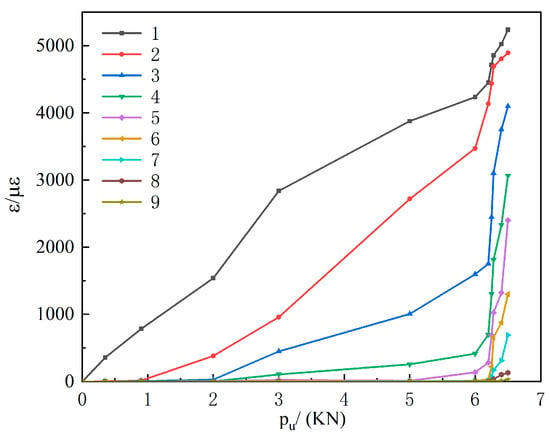
Figure 11.
Load–strain curves at measurement points 1–9 for group M0.
Figure 12 presents gauge-strain profiles plotted against distance from the loading end for specimens subjected to sulfate freeze–thaw cycles under varying applied loads. The slope of each profile corresponds to the bond stress between adjacent gauges. For the MPC group without cycling (Figure 12a), at 0.9 kN, only gauge 1 at the free end registered strain. As the load increased, strain at gauge 1 rose while gauges farther from the loading end recorded progressively lower strains. The slope between gauges 1 and 2 decreased, then increased, and decreased again, indicating an initial increase in bond force that was subsequently transmitted toward the free end. When the inter-gauge slope approaches zero, the CFRP–concrete bond is effectively negligible. Further load increases then produces failure because the bond at the free end cannot sustain the load transferred from the loading end.
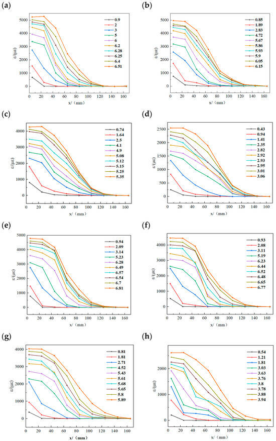
Figure 12.
Strain distribution at different loads (load unit: kN): (a) M0; (b) MD25; (c) MD50; (d) MD75; (e) E0; (f) ED25; (g) ED50; (h) ED75.
Figure 12e shows the EP group without cycling. The strain pattern remains similar, with strain spreading from the loading end toward the free end as the load increases, the free end becomes overloaded, and the specimen breaks. Figure 12 also shows that strain magnitudes in both EP and MPC groups decline progressively with increasing numbers of sulfate freeze–thaw cycles. At equal cycle counts, MPC specimens exhibit larger peak strains than EP specimens, indicating greater ductility. However, MPC gauge strains decrease more markedly after freeze–thaw exposure. Specifically, MPC maximum strain fell from 5280 με at M0 to 2545.15 με after 75 cycles (≈51% reduction), whereas EP maximum strain fell from 4790.43 με at E0 to 2623.34 με at ED75 (≈45% reduction). Moreover, the load that triggers interfacial delamination at the loading end is lower for MPC than for EP specimens.
In summary, EP-bonded specimens exhibit superior resistance to sulfate freeze–thaw degradation compared with MPC-bonded specimens. This difference stems from distinct penetration behaviors and associated erosion pathways and expansion-stress mechanisms. Rapid setting of MPC limits penetration of hydration products into CFRP fiber bundles. Instead a thin interfacial film forms, and the pore content within this film is a primary determinant of bond strength [56,57]. When specimens are exposed to sulfate solution, the fluid infiltrates the adhesive–concrete interface through these detrimental pores [58]. Temperature changes promote sodium sulfate crystallization in the pores; crystal growth exerts expansive pressure on pore walls and causes interconnection of pore defects, transmitting stress to weak bonding zones [59]. Chemical interactions between the sulfate solution and the interface further facilitate crack initiation and linkage [60,61]. Simultaneously, repeated freezing and thawing of the pore fluid generates pore pressures associated with the water-ice phase transition, driving progressive fragmentation and delamination at the MPC adhesive and concrete interface [62]. Collectively, these processes lead to rapid bond strength loss, observed as premature debonding at the loaded end and abrupt decreases in monitored strain. By contrast, EP exhibits superior flowability and penetrability, enabling deeper penetration into CFRP fibers and concrete pores [63] and forming a continuous, dense barrier that blocks most sulfate ingress paths [64]. Accordingly, freeze–thaw stresses concentrate more on external concrete than on the adhesive interface, which undergoes milder degradation. Nonetheless, full EP penetration and stiffening can make the CFRP–adhesive assembly more rigid and less ductile, so despite higher retained bond strength, the system may experience brittle failure at ultimate loads.
Figure 13 plots the strain at gauge 1 at CFRP delamination. With increasing cycle number, the ratio of the load corresponding to a reduced 1–2 gauge slope to the total load decreases, indicating progressive deterioration of loaded-end strain at failure. Larger cycle counts produce larger reductions in maximum strain. For 0–50 cycles, MPC specimens show higher strains than EP specimens. At 75 cycles, both groups display abrupt strain drops, with EP strains remaining higher than MPC. This indicates severe damage between 50 and 75 cycles and greater susceptibility of MPC-bonded double shear specimens to sulfate freeze–thaw damage than EP-bonded specimens. Higher delamination strain of the CFRP sheet indicates greater post-damage ductility. As shown in Figure 13, MPC group generally exhibit higher delamination strains than EP group. This difference reflects EP’s higher penetrability, which produces a denser CFRP–concrete interface. Although this denser interface partially mitigates deterioration from sulfate-induced freeze–thaw cycles, it increases brittleness and reduces deformability at failure. Consequently, delamination strains in EP specimens do not reach MPC levels until after 75 cycles.
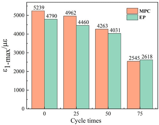
Figure 13.
Strain at gauge 1 at CFRP delamination.
3.5. Stress Distribution
Using the measured gauge strains and a difference method, the average bond shear stress at midpoints between adjacent gauges was computed. The resulting average shear-stress distributions under sulfate freeze–thaw cycles are plotted in Figure 14. MPC and EP specimens show similar stress-distribution evolution. At low loads, shear stress concentrates near the loading end and decreases with distance, producing an overall concave profile with peak stress between gauges 1 and 2. As load increases, the shear-stress concentration shifts away from the loading end (profile becomes convex, peak moves to gauges 2–3). At higher loads, the peak shifts further toward the free end (appearing between gauges 3–4 and 4–5) while bond shear stress at the loading end approaches zero.
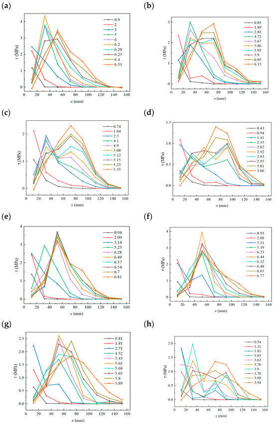
Figure 14.
Average bond shear-stress distribution curves (load unit: kN): (a) M0; (b) MD25; (c) MD50; (d) MD75; (e) E0; (f) ED25; (g) ED50; (h) ED75.
Figure 14 further indicates that the maximum bond shear stress for both specimen groups declines with increasing sulfate freeze–thaw cycles. MPC peak shear stress fell from 4.34 MPa initially to 1.39 MPa after 75 cycles (about 67% reduction). EP peak fell from 3.69 MPa at E0 to 1.97 MPa at E75 (about 46% reduction). Thus, MPC exhibits a larger absolute reduction. Moreover, peak shear-stress migration toward the free end is less pronounced for MPC specimens than for EP specimens, i.e., load transfer toward the free end occurs over a shorter distance in MPC-bonded double shear specimens.
Figure 15 schematically illustrates the stress-evolution mechanism during a double shear test of CFRP–concrete specimens. At low loads, the interface remains largely intact and shear stress concentrates near the loading end (Figure 15a). In this stage, the load-transfer path is short and efficient, producing cooperative deformation between the CFRP and the concrete. The shear-stress distribution is therefore steep and concave. As the load increases, damage accumulates in the adhesive at the loading end and microcracks develop, causing the interfacial stress field to redistribute. Consequently, shear stress near the loading end decreases, and the peak shear stress migrates toward the free end. The distribution curve changes from concave to mildly convex (Figure 15b). When the migrated peak reaches the interfacial bond strength, the original anchorage zone at the loading end fully delaminates, and cracks form, so the load is rapidly transferred toward the free end. Because the free segment has limited interfacial load capacity, interfacial cracks propagate with further loading, leading to CFRP delamination and specimen failure (Figure 15c).
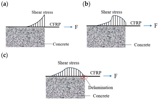
Figure 15.
CFRP–concrete bond shear-stress distribution modes: (a) initial loading; (b) mid-stage loading; (c) late-stage loading.
3.6. Effective Bond Length
Research indicates an effective bond length exists at the CFRP–concrete interface. When the actual bonded length is shorter than this effective length, the interface shear force increases with increasing bonded length, whereas once the actual bonded length exceeds the effective length, the shear force becomes insensitive to further increases in bonded length [50,65,66]. Several models have been proposed to compute the effective bond length, including those of Tanaka [67], Chaallal [68], and Chen and Teng [50]. In this study, the Chen and Teng model is modified to predict the effective bond length for CFRP–concrete joints bonded with MPC- and EP-based adhesives in the high-salinity, cold regions of Western China.
The original Chen and Teng model accounts for the CFRP laminate elastic modulus, CFRP thickness, and concrete compressive strength and is appropriate for typical environments. Based on laboratory tests, this work incorporates the effects of combined sulfate exposure and freeze–thaw cycling and proposes a corrected model for the effective bond length when MPC or EP is used as the adhesive in the targeted climatic conditions. The model expressions for MPC- and EP-based adhesives are given in Equations (1) and (2), respectively.
where represents the effective bond length for MPC-bonded systems when MPC is used as a binder. accounts for the elastic modulus of the CFRP sheet (GPa). indicates the thickness of the CFRP sheet (mm). denotes the stiffness of CFRP (kN/mm). is the concrete’s compressive strength (MPa). is the influence coefficient for the MPC-bonded effective bond length, and represents the number of freeze–thaw cycles.
where represents the effective bond length for EP-bonded systems when EP is used as a binder. is the influence coefficient for the EP-bonded effective bond length.
Using strain values recorded at the measurement points at maximum applied load, the bonded length corresponding to strains between 2% and 98% was adopted as the effective bond length of the double shear specimen interface. Experimental results were compared with the proposed model. The variation in effective bond length with the number of sulfate freeze–thaw cycles is plotted in Figure 16. Both specimen groups exhibit a progressive increase in effective bond length with increasing cycle number. The MPC group increased from 115.16 mm at 0 cycles to 127.65 mm (a 9.43% increase), and the EP group increased from 116.92 mm to 138.22 mm (a 15.40% increase). The coefficients of determination for the proposed models are R2 = 0.98 for the MPC-based model and R2 = 0.99 for the EP-based model, indicating strong predictive accuracy.
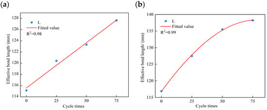
Figure 16.
Variation in effective bond length with number of freeze–thaw cycles: (a) MPC-bonded specimens; (b) EP-bonded specimens.
3.7. Local Interface Bond–Slip Analysis
- (1)
- Bond–slip curves of double shear specimens
For the local bond–slip analysis of degraded CFRP–concrete interfaces, the loaded end capable of bearing load was selected for study. The following assumptions were made in this study: the CFRP laminate behaves as a linear elastic material, the concrete remote from the bonded interface remains undeformed, strain varies linearly between adjacent measurement points, and no relative slip occurs at the free end. Integrating the strain distribution along the CFRP from the free end to a point at distance and accounting for the discontinuous arrangement of the strain gauges yields the local slip expression shown in Equation (3).
where represents the slip at measurement point i, is the strain at point i, indicates the distance from point i to the free end, with i ∈ [1, n − 1], n being the number of strain gauges, and . Calculate the slip at the midpoint as the average of the two adjacent points.
The expression for slip at the midpoint between two adjacent measurement points is given in Equation (4).
Substituting the experimental data into Equations (3) and (4) yields the midpoint slip between adjacent measurement points. From these results, the bond–slip curves for double shear specimens bonded with MPC and EP were plotted (Figure 17). Both adhesives show an approximately linear increase in slip with load during the initial stage, followed by a slower, plateauing increase near the ultimate load. Comparison of M0 and E0 indicates that MPC-bonded specimens sustain slightly lower peak loads than EP-bonded specimens, while exhibiting similar overall bond behavior. After sulfate freeze–thaw cycles, the initial-stage slope of the bond–slip curves decreases with increasing cycle number for all specimen groups, indicating degradation of the CFRP–concrete interface bond and corresponding reductions in slip and slip stiffness.
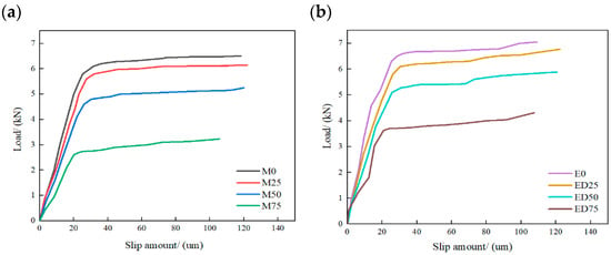
Figure 17.
Comparative analysis of bond–slip curves for double shear specimens: (a) MPC-bonded specimens; (b) EP-bonded specimens.
- (2)
- Local interface bond–slip constitutive relation
Accurate characterization of the CFRP–concrete bond–slip constitutive law is essential for reliable modeling of bonded components. Because bond–slip curves at different measurement points display similar trends [69] while data at the free end are highly scattered, this study analyzes the midpoint between measurement points 1 and 2 at the loaded end.
Figure 18 presents the local interface bond–slip curves for double shear specimens bonded with MPC and EP. Under sulfate freeze–thaw cycles, the bond–slip response for both adhesives can be divided into three stages. In the initial stage, interfacial shear stress rises rapidly with similar slopes across specimen groups. With increasing slip, interfacial shear stress attains a peak at a relatively small slip value. After the peak, the curve enters a softening stage. Shear stress declines rapidly with further slip, and interface debonding initiates. Continued slip transfers load progressively toward the free end until the free end can no longer sustain the load, and failure occurs. Figure 18 also shows that, as cycle number increases, peak interfacial shear stress decreases markedly and the slip at peak shifts to smaller values, indicating pronounced deterioration of bond–slip behavior under sulfate freeze–thaw exposure. EP-bonded specimens are more sensitive to this deterioration than MPC-bonded specimens.
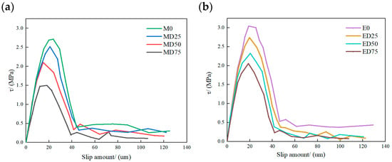
Figure 18.
Local interfacial bond–slip curves for MPC and EP specimen groups: (a) MPC; (b) EP.
Equation (5) [70] is used to describe the local CFRP–concrete bond–slip curves for both adhesives.
where indicates bond stress, represents the maximum bond stress at the interface, , s is the interface slip amounts, is the slip during the elastic phase of the interface, . is the slip values corresponding to parameter , , is the tensile strengths of concrete, A and B are curve parameters linked to initial stiffness and peak points, , , is the parameter describing the descending curve section, and are fitting coefficients, is the width coefficient of CFRP–concrete, and is the initial stiffness of the bond-slip behavior.
Figure 19 shows the bond–slip model curves fitted with Equation (5) for all specimen groups. Prior to sulfate freeze–thaw exposure, both adhesive groups exhibit similar curve shapes. As the cycle number increases, peak stress decreases, and the slip at peak shifts slightly toward smaller values, indicating reduced maximum shear stress, lower slip capacity, and diminished load-bearing ability. Curve fitting yields coefficients of determination R2 of 0.96, 0.95, 0.95, and 0.93 for M0, MD25, MD50, and MD75, respectively, and 0.96, 0.98, 0.98, and 0.98 for E0, ED25, ED50, and ED75, respectively, demonstrating good fit quality.
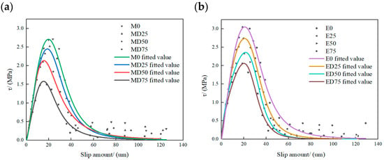
Figure 19.
Fitted bond–slip model curves for double shear specimens: (a) MPC fitted curve; (b) EP fitted curve.
4. Conclusions
This study examined the interfacial bond performance of CFRP–concrete bonded with MPC or EP under coupled exposure to a 5% sulfate solution and freeze–thaw cycling. The main conclusions are summarized below.
- (1)
- Under sulfate freeze–thaw cycles, most failures in both groups occurred near the concrete substrate side of the adhesive–concrete interface. EP specimens primarily exhibited shear failure of the concrete substrate, whereas MPC specimens mainly exhibited adhesive layer–concrete peeling. This contrast reflects the MPC adhesive’s lower permeability and greater post-freeze–thaw ductility, which favor interfacial peeling, whereas EP forms a dense barrier layer that provides higher initial bond strength but fails in a brittle manner.
- (2)
- The MPC group showed higher peak strains than the EP group by 9.28%, 10.13%, 5.99%, and 0.86% at 0, 25, 50, and 75 cycles, respectively, indicating greater ductility. Accordingly, MPC specimens can absorb more deformation energy before failure, thereby delaying damage propagation.
- (3)
- With increasing sulfate freeze–thaw cycles, the interfacial load capacity of both MPC- and EP-bonded specimens declined. The peak bond stress decreased, while the effective bond length generally increased with cycle number. After 75 cycles, compared with EP specimens, MPC specimens exhibited 16.56% lower interfacial load capacity, 21.53% lower peak bond stress, and a 6.03% shorter effective bond length. Thus, bond deterioration under sulfate freeze–thaw cycles was slightly greater for MPC than for EP.
- (4)
- Predictive models for effective bond length and for bond–slip behavior were calibrated to the experimental data for MPC and EP adhesives. The effective-bond-length model achieved R2 = 0.98 for the MPC group and R2 = 0.99 for the EP group. The bond–slip model produced R2 ranges of 0.93–0.96 (MPC) and 0.96–0.98 (EP), indicating close agreement with the experimental results.
In summary, although MPC-bonded interfaces exhibited slightly greater bond degradation under sulfate freeze–thaw cycling than EP-bonded interfaces, MPC demonstrated superior ductility and sustained larger deformations before failure. This ductility partially mitigates brittle interfacial failure and enhances overall structural stability. Therefore, when selecting MPC as an adhesive, practitioners should explicitly consider and exploit its ductile behavior in design and detailing. This study provides guidance for selecting CFRP–concrete adhesives in China’s cold, arid, saline–alkaline regions and may inform adhesive choice in other areas exposed to severe sulfate freeze–thaw cycles.
Author Contributions
Q.W.: Writing—review & editing, Writing—original draft, Conceptualization. J.Z.: Writing—review & editing, Resources, Methodology. W.H.: Writing—review & editing, Methodology. S.H.: Data curation, Conceptualization. Y.Z.: Data curation. P.H.: Data curation. Y.N.: Writing—original draft. All authors have read and agreed to the published version of the manuscript.
Funding
This research was funded by the National Natural Science Foundation of China (52068043).
Data Availability Statement
The original contributions presented in this study are included in the article. Further inquiries can be directed to the corresponding author.
Acknowledgments
The authors gratefully acknowledge the financial support by the National Natural Science Foundation of China. The technical support by the National and Local Joint Engineering Laboratory of Road and Bridge Engineering Disaster Prevention and Control Technology of Lanzhou Jiaotong University is also acknowledged.
Conflicts of Interest
The authors declare that they have no known competing financial interests or personal relationships that could have appeared to influence the work reported in this paper.
References
- Naderi, M.; Rahbari, R. Efficiency of coating layers used for harsh environmental conditions protection of CFRP–strengthened concrete. J. Build. Eng. 2021, 44, 102892. [Google Scholar] [CrossRef]
- Liu, J.; Zhang, B.L.; Chen, F.J. CFRP–strengthened shear walls: Combined effects of CFRP and reinforcement ratio. Int. J. Mech. Sci. 2024, 282, 109634. [Google Scholar]
- Řepka, J.; Vlach, T.; Hájek, J. Flexural behavior of hollow HPC beams with cross–wound CFRP shear reinforcement. Eng. Struct. 2025, 322, 119055. [Google Scholar] [CrossRef]
- Souphavanh, S.; Sonoda, S. Impact Response in Flexural Strengthening of Reinforced Concrete Beams with CFRP Grid and PCM. Int. J. Civ. Eng. 2025, 23, 539–562. [Google Scholar]
- Teng, J.G. Behaviour of GFRP–strengthened RC cantilever slabs. Constr. Build. Mater. 2001, 15, 339–349. [Google Scholar] [CrossRef]
- Zang, Y.M.; Zhan, Y.L.; Liang, S.X. Study on the effects of steel bar diameter and anchorage length on bond-slip characteristics of reinforced concrete under freeze–thaw cycles. Constr. Build. Mater. 2025, 460, 139786. [Google Scholar] [CrossRef]
- Mei, X.F.; Zhang, Y.M.; Ni, D.Y. Analysis of the ion diffusion mechanism affecting the durability of concrete in saline–alkali soils in Western China. Constr. Build. Mater. 2025, 475, 141213. [Google Scholar] [CrossRef]
- Zhang, Y.S.; Jia, J. Salt-Lake Basin Bedrock Weathered Crust Gas Reservoir in the Altun Mountains Front of the Qaidam Basin, Western China. Acta Geol. Sin. 2023, 97, 1555–1567. [Google Scholar] [CrossRef]
- Wang, X.; Petrů, M. Mode I fracture evaluation of CFRP-to-concrete interfaces subject to aggressive environments agents: Freeze-thaw cycles, acid and alkaline solution. Compos. Part B Eng. 2019, 168, 581–588. [Google Scholar] [CrossRef]
- Jiang, F.; Yang, Q.; Wang, Y.; Wang, P.; Hou, D.; Jin, Z. Insights on the adhesive properties and debonding mechanism of CFRP/concrete interface under sulfate environment: From experiments to molecular dynamics. Constr. Build. Mater. 2021, 269, 121247. [Google Scholar] [CrossRef]
- Carloni, C.; Verre, S.; Sneed, L.H. Open issues on the investigation of PBO FRCM-Concrete debonding. Compos. Struct. 2022, 299, 116062. [Google Scholar] [CrossRef]
- Ciupack, Y.; Sternsdorff, S. Crack repair with CFRP patches and toughened EP adhesives. Adhäs. Kleb. Dicht. 2023, 67, 12–19. [Google Scholar] [CrossRef]
- Firmo, J.P.; Correia, J.R.; Pitta, D. Bond Behavior between Near–Surface–Mounted CFRP Strips and Concrete at High Temperatures. J. Compos. Constr. 2015, 19, 04014071. [Google Scholar] [CrossRef]
- Deng, J.; Surahman, R.; Huang, H. Improving bonding performance of PCM–concrete interface under elevated temperatures by using different adhesives. J. Adhes. Sci. Technol. 2024, 38, 4220–4235. [Google Scholar] [CrossRef]
- Huang, Y.Q.; Wong, C.K.C.; Zheng, J.S. Bisphenol A (BPA) in China: A review of sources, environmental levels, and potential human health impacts. Environ. Int. 2012, 42, 91–99. [Google Scholar] [CrossRef]
- Quan, D.; Zhao, G.Q.; Scarselli, G. Co-curingg bonding of carbon fibre/epoxy composite joints with excellent structure integrityusing carbon1 fibre/PEEK tapes. Compos. Sci. Technol. 2022, 227, 109567. [Google Scholar] [CrossRef]
- Walling, S.A.; Provis, J.L. Magnesia–Based Cements: A Journey of 150 Years, and Cements for the Future? Chem. Rev. 2016, 116, 4170–4204. [Google Scholar] [CrossRef]
- Fang, B.; Hu, Z.; Shi, T.; Liu, Y.; Wang, X.; Yang, D.; Zhu, K.; Zhao, X.; Zhao, Z. Research progress on the properties and applications of magnesium phosphate cement. Ceram. Int. 2023, 49, 4001–4016. [Google Scholar] [CrossRef]
- Ding, Z. Study on an Improved Phosphate Cement Binder for the Development of Fiber–Reinforced Inorganic Polymer Composites. Polymers 2014, 6, 2819–2831. [Google Scholar] [CrossRef]
- Nie, S.; Guo, A.F.; Feng, H. Bonding properties of composite interface composed of concrete/magnesium phosphate cement–based ECC/CFRP plate. J. Build. Eng. 2024, 90, 109486. [Google Scholar] [CrossRef]
- Sun, W.; Zheng, Y.; Zhou, L.Z. A study of the bond behavior of FRP bars in MPC seawater concrete. Adv. Struct. Eng. 2021, 24, 1110–1123. [Google Scholar] [CrossRef]
- Li, Y.; Bai, W.; Shi, T. A study of the bonding performance of magnesium phosphate cement on mortar and concrete. Constr. Build. Mater. 2017, 142, 459–468. [Google Scholar] [CrossRef]
- Ma, J.; Wang, H.Y.; Tian, Y.W. Preparation of Nanoscale β–Zeolite by Microwave Radiation Method. Bull. Chin. Ceram. Soc. 2006, 25, 10–12. [Google Scholar]
- Li, J.; Zhang, W.; Cao, Y. Laboratory evaluation of magnesium phosphate cement paste and mortar for rapid repair of cement concrete pavement. Constr. Build. Mater. 2014, 58, 122–128. [Google Scholar] [CrossRef]
- Li, Y.; Bai, W. Research on Axial Compression Test of CFRP Confined Concrete Column With MPC. J. Beijing Univ. Technol. 2017, 43, 467–472. [Google Scholar]
- Yao, Y.; Wang, Z.; Wang, L. Durability of concrete under combined mechanical load and environmental actions: A review. J. Sustain. Cem. Based Mater. 2012, 1, 2–15. [Google Scholar] [CrossRef]
- Sarkar, A.K. Phosphate Cement-based fast-setting bonders. Am. Ceram. Soc. Bull. 1990, 69, 234–238. [Google Scholar]
- Yuan, J.; Zhang, Z.P.; Chen, X. Microstructures and Properties of Modified Magnesium Phosphate Cement Mortar Prepared at Low Temperatures and Subjected to Freeze-Thaw Cycling at Early Ages. J. Wuhan Univ. Technol. Mater. Sci. Ed. 2025, 40, 427–438. [Google Scholar] [CrossRef]
- Zhu, D.; Li, Z.; Xing, F. Chemical durability investigation of magnesium phosphosilicate cement. Key Eng. Mater. 2006, 302–303, 275–281. [Google Scholar] [CrossRef]
- Li, Y.; Shi, T.; Li, J. Effects of fly ash and quartz sand on water–resistance and salt–resistance of magnesium phosphate cement. Constr. Build. Mater. 2006, 105, 384–390. [Google Scholar] [CrossRef]
- Li, C.Z.; Meng, X.K.; Zhu, J.C. Corrosion resistance of magnesium phosphate cement under long–term immersion in different solutions. J. Build. Eng. 2023, 66, 105879. [Google Scholar] [CrossRef]
- Yang, B.; Ji, Y. Sulfate Freeze–Thaw Resistance of Magnesium Potassium Phosphate Cement Mortar. Materials 2022, 15, 3342. [Google Scholar] [CrossRef]
- Shan, C.M.; Yang, J.M.; Chen, Y.D. Experimental study on salt freeze-thaw resistance of magnesium potassium phosphate cement paste in coastal areas. Bull. Chin. Ceram. Soc. 2019, 38, 3687–3694. [Google Scholar]
- Jun, L.; Yongsheng, J.; Linglei, Z.; Benlin, L. Resistance to sulfate attack of magnesium phosphate cement–coated concrete. Constr. Build. Mater. 2019, 195, 156–164. [Google Scholar] [CrossRef]
- Li, J.; Ji, Y.; Huang, G.; Zhang, L. Microstructure evolution of a magnesium phosphate protective layer on concrete structures in a sulfate environment. Coatings 2018, 8, 140. [Google Scholar] [CrossRef]
- Li, Y.; Shi, T.; Li, Y.; Bai, W.; Lin, H. Damage of magnesium potassium phosphate cement under dry and wet cycles and sulfate attack. Constr. Build. Mater. 2019, 210, 111–117. [Google Scholar] [CrossRef]
- Yan, K.; Song, Y.B.; Yuan, T.F. Comparative axial compressive behavior of CFRPs-confined columns containing high-performance magnesium phosphate cement-based composites and epoxy resin. Case Stud. Constr. Mater. 2025, 23, e05340. [Google Scholar] [CrossRef]
- Feng, X.Z.; Ren, J.G.; Liu, Q.L. Tailoring magnesium potassium phosphate cement-based adhesive for the improved bonding performance of CFRP/concrete interface. Constr. Build. Mater. 2024, 453, 139121. [Google Scholar] [CrossRef]
- Zhang, J.W.; Li, H.; Liu, S.W. Effects of sulfate and freeze–thaw cycles on the bond behavior of CFRP–concrete interface. Constr. Build. Mater. 2023, 368, 130368. [Google Scholar] [CrossRef]
- GB/T 8077-2023; Methods for Testing Uniformity of Concrete Admixtures. State Administration for Market Regulation & Standardization Administration of China: Beijing, China, 2023.
- Yao, Y.Y.; Zhang, D. Mechanical and microscopic properties of magnesium phosphate cement-based concrete with fly ash. J. Build. Eng. 2024, 91, 109640. [Google Scholar] [CrossRef]
- DL/T 5150–2017; Test Code for Hydraulic Concrete. China Electric Power Press: Beijing, China, 2017.
- GB/T 50081–2019; Standard for Test Methods of Concrete Physical and Mechanical Properties. China Architecture and Building Press: Beijing, China, 2019.
- Liu, S.W.; Zhang, J.W.; Zhao, J.C. Effect of sulfate dry-wet cycles on the interfacial bonding performance of carbon fiber reinforced epoxy resin-concrete. Acta Mater. Compos. Sin. 2018, 35, 16–23. [Google Scholar]
- Guo, S.H.; Zhang, J.R.; Gao, Y. Effect of Adhesive Thickness on Bond Behavior of CFRP Plate-concrete Interface. J. Highw. Transp. Res. Dev. 2015, 32, 87–91,97. [Google Scholar]
- Hawileh, R.; Douier, K.; Gowrishankar, P. Durability of externally strengthened concrete prisms with CFRP laminates and galvanized steel mesh attached with epoxy adhesives and mortar. Compos. Part C Open Access 2024, 14, 100493. [Google Scholar] [CrossRef]
- Jiang, L.; Niu, D.T. Deterioration Law of Concrete under Combined Action of Sulfate and Freeze–Thaw Cycles. J. Cent. South Univ. (Sci. Technol.) 2016, 47, 3208–3216. [Google Scholar]
- Jiang, L. Durability of concrete under sulfate attack exposed to freeze–thaw cycles. Cold Reg. Sci. Technol. 2015, 112, 112–117. [Google Scholar] [CrossRef]
- Ren, H.T.; Hu, A.N.; Zhao, G.F. Influence of Freeze–Thaw Cycles on Mechanical Performance of Concrete Beams Reinforced with Glass Fiber Cloth. J. Civ. Eng. 2004, 37, 104–110. [Google Scholar]
- Chen, J.F.; Teng, J.G. Anchorage strength models for FRP and steel plates bonded to concrete. J. Struct. Eng. 2001, 127, 784–791. [Google Scholar] [CrossRef]
- Xiong, H.X.; Zhang, Q.; Guo, S.H. Adhesive thickness effect upon the CFRP plate–concrete interface bond behaviours. Eng. Res. Express 2025, 7, 015101. [Google Scholar] [CrossRef]
- Yang, Q.B. Mechanism of Salt Freezing Damage in Concrete (II): Freeze–Thaw Saturation Degree and Ice Formation Pressure. J. Build. Mater. 2012, 15, 741–746. [Google Scholar]
- Zhang, L.C.; Zhang, A.L.; Wang, Q. Corrosion resistance of wollastonite modified magnesium phosphate cement paste exposed to freeze–thaw cycles and acid–base corrosion. Case Stud. Constr. Mater. 2020, 13, e00421. [Google Scholar] [CrossRef]
- Rahman, M.M.; Islam, A. Application of epoxy resins in building materials: Progress and prospects. Polym. Bull. 2022, 79, 1949–1975. [Google Scholar] [CrossRef]
- Ding, Z.; Li, Z.J. Preparation and Properties of Early–Strength Phosphoaluminate Cement. Chin. J. Mater. Res. 2006, 20, 141–147. [Google Scholar]
- Ma, C. Properties of magnesium phosphate cement containing redispersible polymer powder. Constr. Build. Mater. 2016, 113, 255–263. [Google Scholar] [CrossRef]
- Du, Y.B.; Gao, P.W.; Yang, J.M.; Shi, F.T. Research on the Chloride Ion Penetration Resistance of Magnesium Phosphate Cement (MPC) Material as Coating for Reinforced Concrete Structures. Coatings 2020, 10, 1145. [Google Scholar] [CrossRef]
- Zhang, J.; Yang, H.T.; Hu, X.M. Effect of Steel Fiber on Mechanical Properties and Microstructure of Magnesium Phosphate Cement–Based Concrete Exposed to Water and Sulfate Attack. J. Mater. Civ. Eng. 2023, 35, 04023450. [Google Scholar] [CrossRef]
- Steiger, M.; Asmussen, S. Crystallization of sodium sulfate phases in porous materials: The phase diagram Na2SO4-H2O and the generation of stress. Geochim. Cosmochim. Acta 2008, 72, 4291–4306. [Google Scholar] [CrossRef]
- Zhang, L.W.; Wu, Q.; Akbar, M. Multiscale investigation of differential corrosion mechanisms in magnesium potassium phosphate cement coatings under chloride and sulfate attack. J. Build. Eng. 2025, 112, 113842. [Google Scholar] [CrossRef]
- Torii, K.; Taniguchi, K.; Kawamura, M. Sulfate resistance of high fly ash content concrete. Cem. Concr. Res. 1995, 25, 759–768. [Google Scholar] [CrossRef]
- Zhou, Z.H.; Wang, Q.; Shen, Y.J. Interfacial debonding mechanism of magnesium phosphate cement onto old concrete substrates under freeze-thaw conditions. Compos. Part B Eng. 2024, 268, 111076. [Google Scholar] [CrossRef]
- Manson, J.A.; Chiu, E.H. Permeation of liquid water in a filled epoxy resin. J. Polym. Sci. Polym. Symp. 1973, 41, 95–108. [Google Scholar] [CrossRef]
- Ajir, K.; Toufigh, V.; Ghaemian, M. Protecting ordinary cement concrete against acidic and alkaline attacks utilizing epoxy resin coating. Constr. Build. Mater. 2025, 472, 141003. [Google Scholar] [CrossRef]
- Yuan, H.; Teng, J.G.; Seracino, R. Full–range behavior of FRP–to–concrete bonded joints. Eng. Struct. 2004, 26, 553–565. [Google Scholar] [CrossRef]
- Nakaba, K.; Kanakubo, T.; Furuta, T. Bond behavior between fiber–reinforced polymer laminates and concrete. Struct. J. 2001, 98, 359–367. [Google Scholar]
- Rizkalla, S.; Hassan, T. Design recommendations for the use of FRP for reinforcement and strengthening of concrete structures. Prog. Struct. Eng. Mater. 2003, 5, 16–28. [Google Scholar] [CrossRef]
- Chaallal, O.; Nollet, M. Perraton, Strengthening of reinforced concrete beams with externally bonded fiber–reinforced–plastic plates. Can. J. Civ. Eng. 1998, 25, 62–70. [Google Scholar] [CrossRef]
- Liu, L.M.; Zhang, W.P.; Gu, X.L. Study on Bond Performance and Durability of Carbon Fiber Sheet to Concrete. Build. Struct. 2006, A1, 788–791. [Google Scholar]
- Lu, X.Z.; Tan, Z.; Ye, L.P. Finite element analysis of interfacial bond behavior between FRP sheet and concrete. Eng. Mech. 2004, 21, 45–51. [Google Scholar]
Disclaimer/Publisher’s Note: The statements, opinions and data contained in all publications are solely those of the individual author(s) and contributor(s) and not of MDPI and/or the editor(s). MDPI and/or the editor(s) disclaim responsibility for any injury to people or property resulting from any ideas, methods, instructions or products referred to in the content. |
© 2025 by the authors. Licensee MDPI, Basel, Switzerland. This article is an open access article distributed under the terms and conditions of the Creative Commons Attribution (CC BY) license (https://creativecommons.org/licenses/by/4.0/).