You are currently viewing a new version of our website. To view the old version click .
Buildings
  • Article
  • Open Access

14 November 2025

Behaviour of Structural Subassemblies of Steel Beams with Corrugated Webs Using Reverse Channel Connections

and
1
Department of Civil Engineering, College of Engineering, University of Bisha, Bisha 67714, Saudi Arabia
2
Department of Structural Engineering, Faculty of Engineering, Al Azhar University, Cairo 11371, Egypt
*
Author to whom correspondence should be addressed.
This article belongs to the Section Building Structures

Abstract

This study uses the finite element (FE) software ABAQUS V 6.14to develop detailed, comprehensive numerical models of the behaviour of restrained structural subassemblies of corrugated web steel beams (SBCW) connected to concrete-filled tubular columns (CFTC) via reverse channel connection. Four different types of web corrugation profiles—trapezoidal (Trap), rectangular (Rec), sinusoidal (Sin), and triangular (Tria)—are numerically modelled and analyzed to evaluate the significance of their influence on structural behaviour. In addition, the effects of flange stiffeners at the point load and web slenderness are examined. Moreover, this study investigates the effects of using four different joint types of reverse channel connection: extended endplate, flush endplate, flexible endplate, and hybrid extended/flexible endplate on the behaviour of SBCW. It is concluded that, by means of corrugated webs for enhancing beam deformation capacity and strength, it is feasible for the beams to achieve a higher load-carrying capacity. The ultimate load of the beams with Trap and Rec corrugated web was higher than that for the flat web beam by about 22% and 18%, respectively, and with the same increase of 10.5% for Tria and Sin corrugation profiles. However, providing the corrugated web beams with flange stiffeners at the point load had a limited effect (+0.7% to +5.1% depending on profile). Moreover, increasing the web thickness to reduce the slenderness ratio (hw/tw) from 250 to 200 can be an effective solution to prolong their load-carrying capacity. In addition, using an extended or flush endplate gave the best behaviour of SBCW connected to concrete-filled tubular columns (CFTC) with an increase of (5.3–31.7%) and (25–30.9%) for flush endplate and extended endplate, respectively, compared to flexible endplate, depending on the web corrugation profile.

1. Introduction

SBCW are commonly used in low- and medium-rise buildings because of their light weight, reducing web stiffeners, economic design, high load carrying capacity and enhancing strength against shear buckling failure. In manufacturing, there are four common web corrugation profiles (trapezoidal, rectangular, sinusoidal, and triangular). Many researchers have experimentally and numerically investigated the behaviour of SBCW with various corrugation profiles. However, most of these studies focused on simply supported beams. For example, researchers Al-Kannoon and Suhiel [], Elamary et al. [], Hasan et al. [], and Ammash and Al-Bader [] carried out experimental tests to investigate the flexural behaviour of simply supported steel beams with different web corrugation profiles (trapezoidal, rectangular, sinusoidal, and triangular) and a flat flange under shear and moment. Landolfo et al. [] experimentally assessed the usage of corrugated webs in cold-formed steel beams. Other researchers experimentally studied the effect of fatigue and cyclic load on trapezoidal corrugated web when subjected to bending and combined bending and shear [,,,]. Al-Mawashee and Al-Kannoon [] performed an experimental study on castellated beams with corrugated webs. Several researchers have performed a few experimental tests and then used numerical modelling as an attractive alternative means of completing the research. This approach has been adopted by many researchers to experimentally and numerically investigate the behaviour of simply supported SBCW with various standard web corrugation profiles under different loading scenarios [,,,,,,]. Beneficial to providing insight into the stress distribution and deformation characteristics and conducting intensive parametric studies, numerical modelling alone has been employed by a great number of researchers to study numerically the behaviour of simply supported SBCW with various web profiles of corrugation under different loading scenarios. For example, Jáger et al. [] built a numerical model to study the behaviour of SBCW under bending. Luo and Edlund [] investigated the effect of various parameters on the shear strength of the trapezoidal corrugated web using a series of FE analyses. De’nan et al. [] used the LUSUS FE programme to investigate the behaviour of triangular corrugated web beams. Kumar et al. [] studied the flexural behaviour of corrugated sheets with different thicknesses, corrugated angles, and corrugation shapes using ANSYS. Mutalib et al. [] carried out intensive parametric analytical studies by using the LUSAS V 13.7 software to determine the effects of various parameters, including web and flange thickness and corrugation angle, on the behaviour of a composite plate girder with corrugated webs. Chan et al. [] performed FE analyses using LUSAS to study the effect of vertical and horizontal corrugation on the strength of steel beams. Al-Kanon and Suhiel [] used ANSYS to analyze five specimens of simply supported beams with flat and various web corrugation profiles, which were subjected to a two-point load. Sayed et al. [] used the FE numerical analysis to study the effect of corrugated web types on the flexure mode shapes and natural frequencies of steel beams. Researchers [,,] presented analytical studies to examine the behaviour of SBCW having cut-outs, under uniform or point load, using ANSYS.
These studies have examined most of the factors affecting the behaviour of SBCW, such as corrugation profiles, corrugation density, failure mechanism, flange stiffener, web slenderness, web cuts, and various loading types. However, so far, most of these existing experimental and numerical simulation studies have considered the behaviour of simply supported SBCW with statically determinate structures in which the real behaviour of the joint is not modelled. In contrast, the publication by Hafsamol and Abraham [] seems to be the only one to have used ANSYS to model SBCW connected to a column using a realistic direct-welded joint to determine the maximum load-carrying capacity of the beam. Reverse channel connection has excellent rotation capacity and moment resistance, which is a critical requirement for ensuring structural robustness []. Therefore, this study has the following four specific objectives:
  • Validate an ABAQUS model vs. the experimental results of Nie et al. [].
  • Develop a 3D finite element model using ABAQUS to study the behaviour of structural subassemblies of SBCW with different web corrugation configurations connected to CFT columns using an extended end-plate reverse channel connection.
  • Perform a parametric study considering various factors, including web corrugation profiles (Trap, Rec, Sin and Tria), flange stiffeners at the point load, and web thickness.
  • Investigate the effects of four different joint types of reverse channel connection: extended endplate, flush endplate, flexible endplate, and hybrid extended/flexible endplate on the load-carrying capacity of SBCW.

2. Finite Element Model

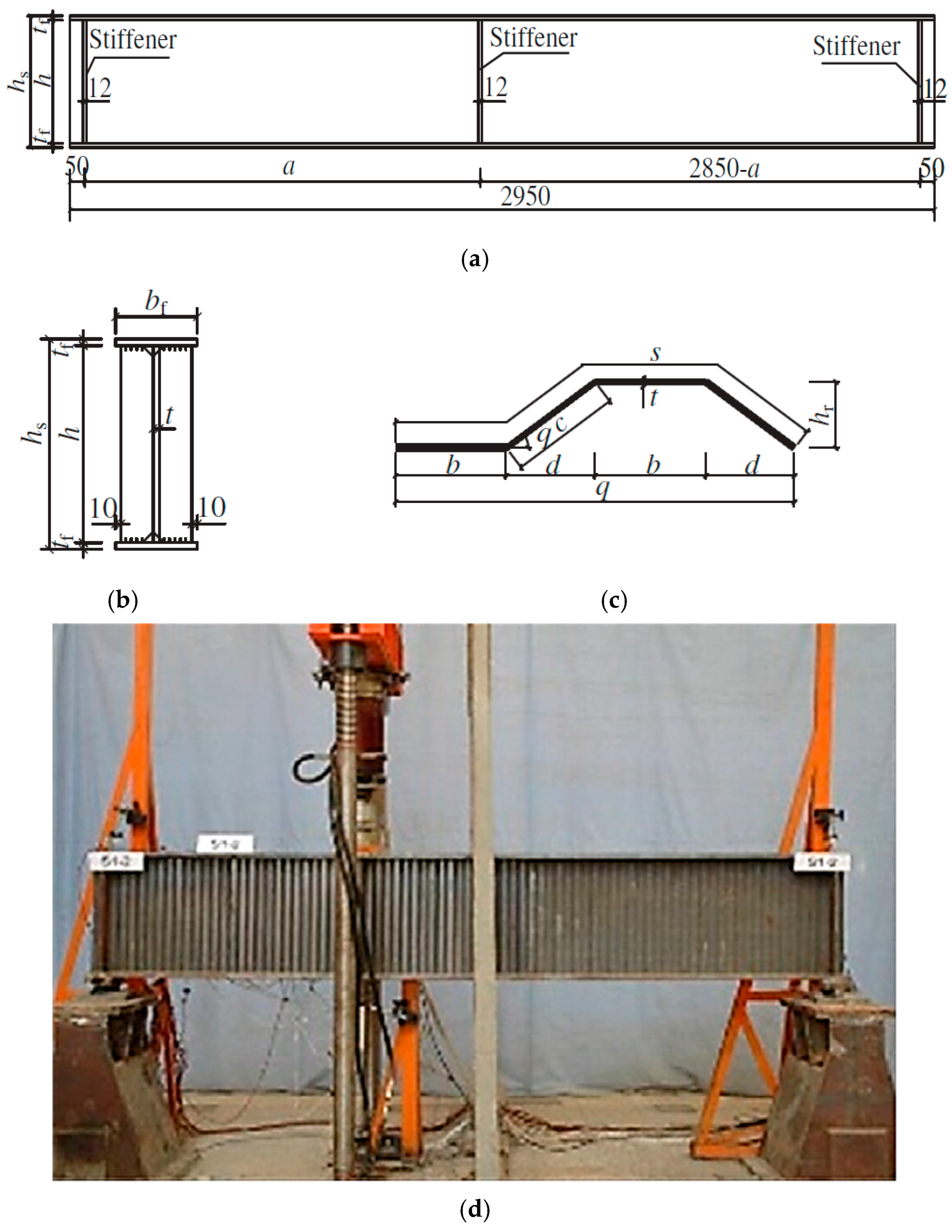
The FE model was validated with the results of experimental test data of a steel beam with a trapezoidal corrugated web conducted by Nie et al. []. Figure 1 represents the geometrical details of the test specimen. In the test setup, the specimen was subjected to a point load so that the web was under constant shear stress. The beam was provided with stiffeners at supports and at the point load to avoid the beam distortion and web crippling due to the influence of concentrated load. Table 1 and Table 2 represent geometric parameters of test beams and geometric parameters of trapezoidal corrugated configuration, respectively, as reported by Nie et al. []. The development of the numerical model and simulation methodology adopted for the validation of the FE model is summarized below:
-
Numerical simulations of the tests of Nie et al. [] were modelled using the nonlinear FE programme ABAQUS [].
-
The beam was modelled using the FE shell element (S4R).
-
To model accurate beam behaviour, several simulations were performed using 50, 35, 20, and 10 mm mesh sizes. The results in Table 3 indicate that the finer mesh size of 10 mm exhibited a ≤3% Pu change relative to the experimental ultimate load. Accordingly, it was selected to simulate accurate beam behaviour.
-
Both geometric and material nonlinearities were considered to perform a nonlinear static analysis. A multilinear stress–strain curve was used to model steel material properties as an isotropic material (see Figure 2).
-
The following parameters were used throughout the analysis for the steel section based on the material property tests of Nie et al. []: yield strength of the web, 385.5 MPa; ultimate strength of the web, 461.2 MPa; elastic modulus, E = 2.06 × 10⁵ MPa; and Poisson ratio, υ = 0.3.
-
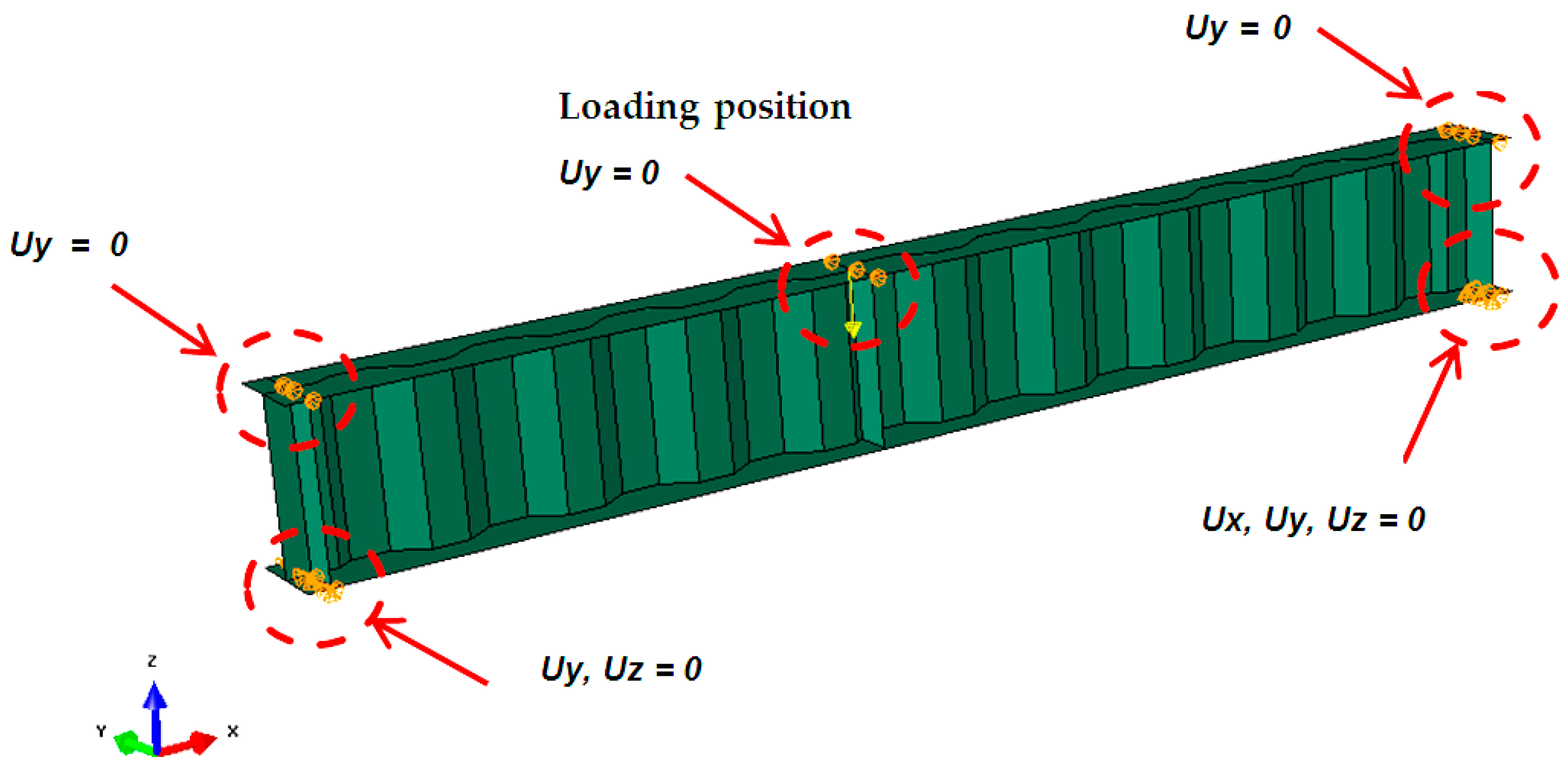
Boundary conditions of the beam in numerical simulations were applied at the loading and supports as the experimental specimens; the left support was modelled as a hinged support and the right support as a roller support, as shown in Figure 1d. Figure 3 summarizes the constrained DOFs of the FE model at each support and load plate.
-
One load was applied across the top flange of the beam and increased gradually until failure.
-
Due to structural geometric imperfections and residual stresses during manufacturing, forming, and processing, geometric initial imperfections in the nonlinear FE models were established and validated. The equivalent geometric imperfections recommended by the standard EN 1993-1-5:2006 [] were used for calculations of initial imperfections of the beam. Accordingly, geometric imperfections obtained from the first buckling mode based on eigenvalue buckling analysis were used and then scaled to simulate the initial imperfection. In simulation, the initial geometric imperfections in the web were estimated by scaling the first buckling mode by a value not more than L/350. The maximum value for the initial geometric imperfections used in validation for all tests was 5 mm. Table 4 shows the ultimate load capacity of test 2-2, using various values of initial geometric imperfections. The results in Table 4 indicate that Pu of the beam depends on initial geometric imperfections. Accordingly, the value that gave the least ΔPu% change relative to the experimental ultimate load was selected to simulate accurate beam behaviour.
-
Two load cases were applied to the beam. The first case was to stimulate the initial imperfection in the form of initial out-of-plane buckling over the web of the beam, when no external load was applied, and then, at the end of this case, after updating the geometry of the beam with the initial imperfection, the second case was applied, until the ultimate load was reached.
-
Static Riks is used for analysis with a minimum increment size of 1 × 10⁻⁵ and a maximum increment size of 0.1 with the default convergence tolerances in Abaqus.
-
The FE simulations were accomplished on the tests of Nie et al. [] with two different trapezoidal corrugated configurations and different geometric parameters of test beams, as reported in Table 2 and Table 3.
Figure 1. Details of test beam (Nie et al. []): (a) elevation; (b) cross section; (c) trapezoidal corrugation; (d) test specimen.
Figure 2. Stress–strain curve of web.
Figure 3. The constrained DOFs at each support and load plate.
Table 1. Geometric parameters of test beams (Nie et al. []).
SpecimenFlange DimensionsTrapezoidal Corrugated Web Parameters
bf (mm)t (mm)a (mm)h (mm)
S1-2150121000460
S1-314660
S1-416760
S1-520860
S2-1200161200260
S2-220360
S2-325460
Table 2. Configuration of trapezoidal corrugation (Nie et al. []).
Corrugated
Configuration
b
(mm)
d
(mm)
θ
(o)
hr
(mm)
s
(mm)
c
(mm)
t
(mm)
S12016371280720.9
S2806448320288
Table 3. Mesh convergence.
Mesh Size (mm)No. of ElementsPu (Kn)δmid (mm)ΔPu%
102760968.553.300.96%
20696183.903.7723.6%
352068106.544.5956.9%
501413111.074.5963.6%
Table 4. Initial geometric imperfections convergence.
Initial Geometric Imperfections (mm)Pu (Kn)δmid (mm)ΔPu%
175.743.2611.38%
270.43.253.53%
364.873.38−4.60%
462.143.24−8.62%
558.463.38−14.03%

3. Validation of the Finite Element Model

The FE model was validated against the experimental results of steel beams with trapezoidal corrugated steel webs, as reported by Nie et al. []. The validation parameters were the failure mode, the load vertical deflection, and the load capacities. The load versus deflection curve and the typical failure modes of the test girders and FE models are shown in Figure 4 and Figure 5, respectively. Table 5 shows comparisons between the experimental and numerical results. There is a good consistency between the FE modelling and test data in terms of load–deflection behaviour and ultimate load, with differences ranging from −3.98% to +3.55% (Mean= −0.48%, Standard deviation = 2.37, RMSE = 2.25). For direct comparison, Figure 4 shows the results of load–deflection curves for the FE modelling together with the measured test data. As can be seen in Figure 4, the load–deflection curves for FE results matched well with the test results in terms of ultimate load and load–deflection behaviour in the linear range for all tests except for the FE behaviour of test S1-5 was stiffer than the test results, whereas the FE behaviour of test S2-1 and S2-3 were softer than the test results. This may be due to the inaccuracy in the test results of Nie et al. []. If we compare the test results in terms of the elastic range of specimens S1-2, S1-3, and S1-4 having the same section profile with variable height (hw = 460, 660, and 760, respectively), it can be observed that, as the beam height increases, the stiffness increases. However, the specimen S1-5 of hw = 860 gave the same stiffness as specimen S1-4 (hw = 760). The specimen S1-5 should be stiffer than specimen S1-4. The FE model results in Table 5 showed the increase in stiffness in the elastic range with the increase in section height. The difference in stiffness of FE results and test results of specimens S2-1 and S2-3 in the elastic range can be justified by the same explanation. Figure 5 compares the modelling and experimental results for deformation and failure modes of the beams. The observed failure mode and deformation characteristics of the beam are modelled satisfactorily by the numerical model. As shown in Figure 5a, due to dense corrugations, the specimens of corrugated configuration S1 failed by global web shear buckling, which is clearly captured by the FE model (see Figure 5b–e). Whereas, due to course corrugations, the specimens of corrugated configuration S2 failed by the local shear buckling over 2 or 3 folds of the web as shown in Figure 5f–i. Consequently, there is a good consistency between the FE modelling and test data in terms of load–deflection behaviour, failure mode, and ultimate load. Accordingly, this provides confidence in the developed FE model in this study and could be considered as an effective method to predict the failure modes and ultimate load capacities of SBCW.
Figure 4. Mid-span deflection versus load for test and FE model: (a) Test S1-2; (b) Test S1-3; (c) Test S1-4; (d) Test S1-5; (e) Test S2-1; (f) Test S2-2; (g) Test S2-3.
Figure 5. Deformed shape (U) and failure mode: (a) Test S1-2 []; (b) FE model S1-2; (c) FE model S1-3; (d) FE model S1-4; (e) FE model S1-5; (f) Test S2-2 []; (g) FE model S2-1; (h) FE model S2-2; (i) FE model S2-3.
Table 5. Comparisons of the experimental and numerical results.

4. Numerical Model of the Behaviour of Restrained Structural Subassemblies of SBCW

The FE model for the structural subassemblies to be simulated in this study is shown in Figure 6. The structural subassemblies in Figure 6 consist of a steel beam connected to two CFT columns. In this study, the beam is connected to a CFT column with the so-called extended reverse channel connection in which the two legs of a channel are welded to the tubular column face and its web connected by a group of bolts to an extended endplate welded to the beam side (see Figure 7). Figure 8 represents the structure assembly dimensions, end conditions of the column, and the applied point load to be simulated in the parametric study. The simulation methodology adopted in modelling the structural subassemblies of SBCW connected to CFTC via reverse channel connection is outlined below:
-
Due to symmetry, half of the structure was modelled so that all nodes at the beam mid-section were fixed in the axial direction, preventing rotation about the two principal axes but allowing the beam to twist about its longitudinal axis. To account for the concrete slab, the beam was assumed to be fully laterally restrained.
-
The “tie” type constraint in ABAQUS was used to simulate the welds between connection components.
-
In modelling the end plate reverse channel connection, many contact pairs existed in the joints. These contact pairs occurred at the interfaces of the following contact points: the bolt shanks and web of the reverse channel and endplate, the bolt heads and web of the reverse channel, and the endplate and web of the reverse channel.
-
The ABAQUS contact function was used to simulate the interaction between the contact pairs. “Surface to surface” contacts with a small sliding option were defined for all contact relationships. The normal contact behaviour was assumed as “Hard contact”. A friction coefficient of 0.3 was assumed for the tangential direction of the contact pairs.
-
As can be seen in Figure 2 (stress–strain curve), a localized reduction in the cross-sectional area of the material after the UTS (Necking) is reached at εp = 0.15. Therefore, the failure load was considered as a large deflection of the beam combined with the spread of plastic strain, exceeding 0.15 at the web and flange at which the beam failed to carry the load. Grey colour in the finite element models represents plastic strain exceeding 0.15.
-
The numerical FE simulations were carried out on steel beams with four different geometrical corrugated web shapes (Trap, Rec, Sin, and Tria), as shown in Figure 9. Table 6 shows the configuration geometry of corrugation profiles.
-
Generally, the simply supported SBCW failed by five different modes of failure:
  • Global web shear buckling.
  • Local shear web buckling.
  • Local flange buckling.
  • Vertical buckling into the web.
  • Yielding of the compression flange.
Figure 6. FE model: (a) structural subassembly with realistic joints; (b) mesh.
Figure 7. Typical reverse channel connection using an extended endplate.
Figure 8. Geometry and end conditions for structure assembly.
Figure 9. Corrugation configurations of web: (a) Trap; (b) Rec; (c) Sin; (d) Tria.
Table 6. Configuration geometry of corrugation profiles.
Corrugated
Configuration
b
(mm)
d
(mm)
θ
(o)
hr
(mm)
s
(mm)
q
(mm)
t
(mm)
Trap404045401921601.7
Rec404090402381601.7
Sin404014401801601.7
Tria404025401771601.7

5. FE Results of Structural Subassemblies of SBCW Without Stiffener

The FE model was built for a flat plate web and different web corrugation configurations (Trap, Rec, Sin, and Tria) without flange stiffener and with web slenderness (hw/tw = 250). Figure 10 shows the applied loads against mid-span deflection curves obtained from the FE modelling. As can be seen, the flat web (FW) specimen and its counterpart exhibited the same initial stiffness and load–deflection behaviour until about 70 mm, at which point the stiffness of the beams decreased. The beam with a flat-web specimen reached its ultimate load at Pu = 164 kN, when the beam failed to carry the applied load. The ultimate load of the beam increased with the use of corrugated webs. Table 7 summarizes the beam’s ultimate load for each profile without flange stiffener (hw/tw = 250). The rate of increase depends on the web corrugation configurations. Trap and Rec corrugated web beams had a higher ultimate load than other corrugation profiles, as shown in Figure 10. The ultimate load of the beams with Trap and Rec corrugated web were 22% and 18%, respectively, higher than that of the flat web beam. However, the Tria and Sin corrugation profiles had the least increase in load-carrying capacity, with the same increase of 10.5%.
Figure 10. Load–mid-span deflection curves for beams without flange stiffener (hw/tw = 250).
Table 7. Pu for beams without flange stiffener (hw/tw = 250).
As shown in Figure 11a, the beam with a flat web failed due to the combined compression flange local buckling and web global buckling. As the beam had no flange stiffener, the buckling in the flat web beam occurred near the point load due to web crippling under the compression flange after its vertical buckling. The flat, slender web beam combined global web and flange buckling. This is due to the absence of a supported stiffener, where there is no additional support to resist the lateral out-of-plane deformation of the web, causing a concentration of compressive loads on the flange, making it more prone to global buckling. Figure 11b–e show overall deformed shapes for all four beams with different web corrugations without flange stiffener. The failure modes had similar failure mechanisms for all four beams, but at different ultimate loads. The failure mechanism started by yielding in the flange, followed by vertical buckling into the web, then the web of the beam buckled locally under compressive loads at the point loads because they had no flange stiffener. As can be seen in Figure 12, the plastic strains are localized at the area of the web adjacent to the compression flange. Grey colour, observed near the compression flange, represents plastic strain exceeding 0.15. It is observed that corrugation prevents web global buckling, which was the common mode of failure for the beam with flat web.
Figure 11. Deformed shape (U) at failure for beams without stiffener: (a) flat web; (b) Rec corrugation; (c) Trap corrugation; (d) Sin corrugation; (e) Tria corrugation.
Figure 12. Plastic strain (PEEQ) at failure for corrugated beams without stiffener: (a) Rec; (b) Trap; (c) Sin; (d) Tria. (U-Scale +1.00 × 100).

6. Effect of Transversal Stiffeners

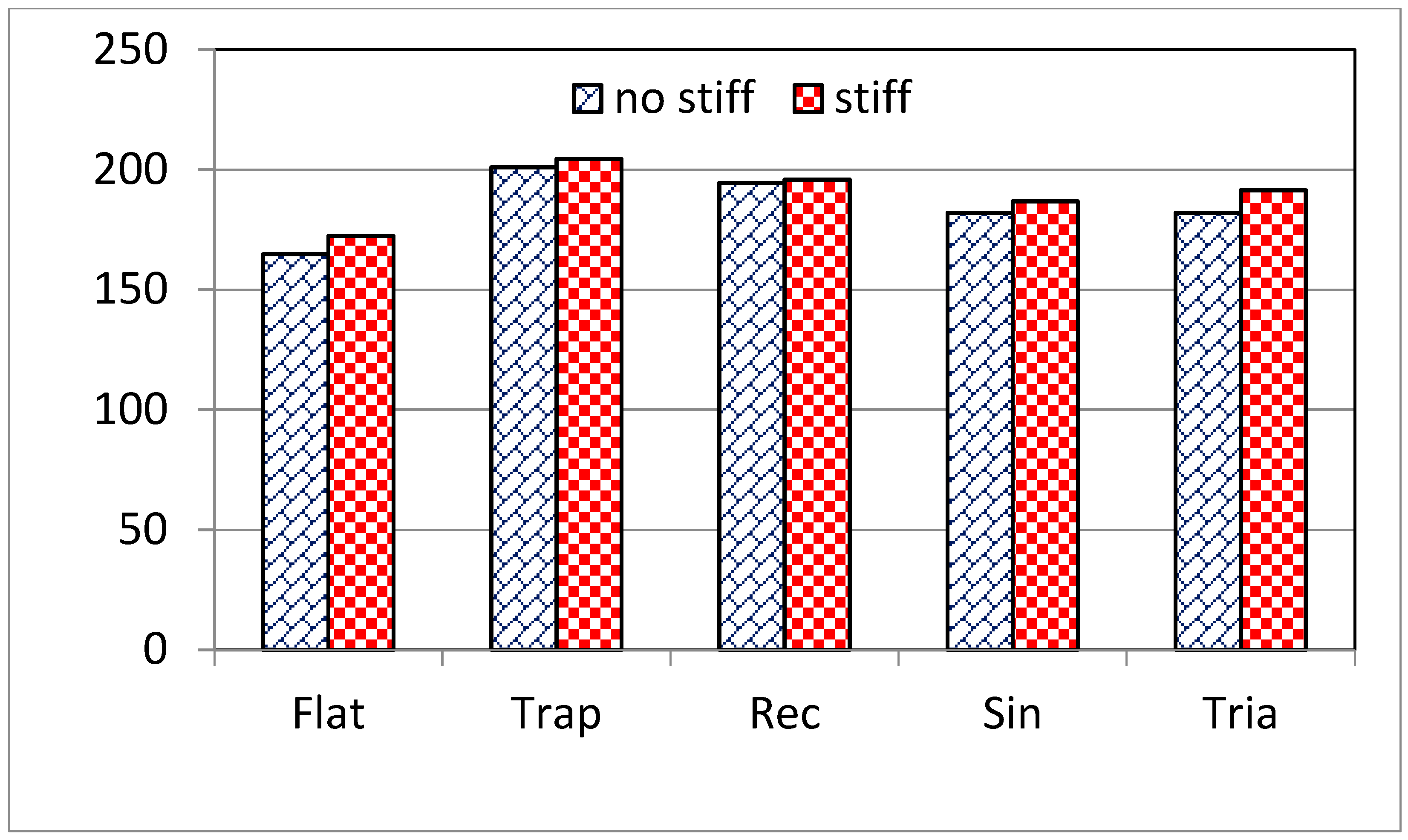
Figure 13 shows a comparison between the load–deflection results of the flat web specimen with those of the different web corrugation profiles (Trap, Rec, Sin, and Tria) with a flange stiffener (see Figure 14 for stiffener dimensions). The beams with a flange stiffener exhibited slightly higher ultimate capacities than the beams without a stiffener. The beam of flat web with a stiffener failed at an ultimate load of about Pu = 172.3 kN, with an increase of about 4.6% compared to the flat beam without a stiffener. Similarly, beams with corrugated webs experienced a slight increase in the load-carrying capacity compared to corrugated web beams without a stiffener. The effect of the flange stiffener depends on the web corrugation profile, as shown in the comparative bar chart in Figure 15. The load-carrying capacity for Tria and Sin web corrugation increased about 5.1% and 2.6%, respectively, compared with those without a stiffener. The ultimate load of beams with Tria and Sin corrugations with a stiffener were Pu = 191.35 kN and Pu = 186.8 kN, respectively, compared to Pu = 182 for both without a flange stiffener. However, their load carrying capacities were less than that for Trap and Rec web corrugations without a flange stiffener. The ultimate load of beams with Trap and Rec corrugations with stiffener were Pu = 204.46 kN and Pu = 195.8 kN compared to Pu = 201 kN and Pu = 194.5 kN without stiffener, representing an increase due to the flange stiffener of about 1.7% and 0.7%, respectively. This is revealed that the stiffener had a lower effect in the case of Trap and Rec web corrugations than Tria and Sin web corrugations. This may be because the folds orientation of Trap and Rec web corrugations provides the web with additional support to resist the lateral out-of-plane deformation of the web, making it less susceptible to buckling under load. However, that was not the case for Tria and Sin web corrugations; therefore, they need an additional stiffener at the load point to overcome the web local buckling failure at point loads and enhance higher load carrying capacity.
Figure 13. Load–mid-span deflection curves for beams with flange stiffener (hw/tw = 250).
Figure 14. Dimensions of the stiffener.
Figure 15. A comparison of Pu for beams without and with flange stiffener (hw/tw = 250).
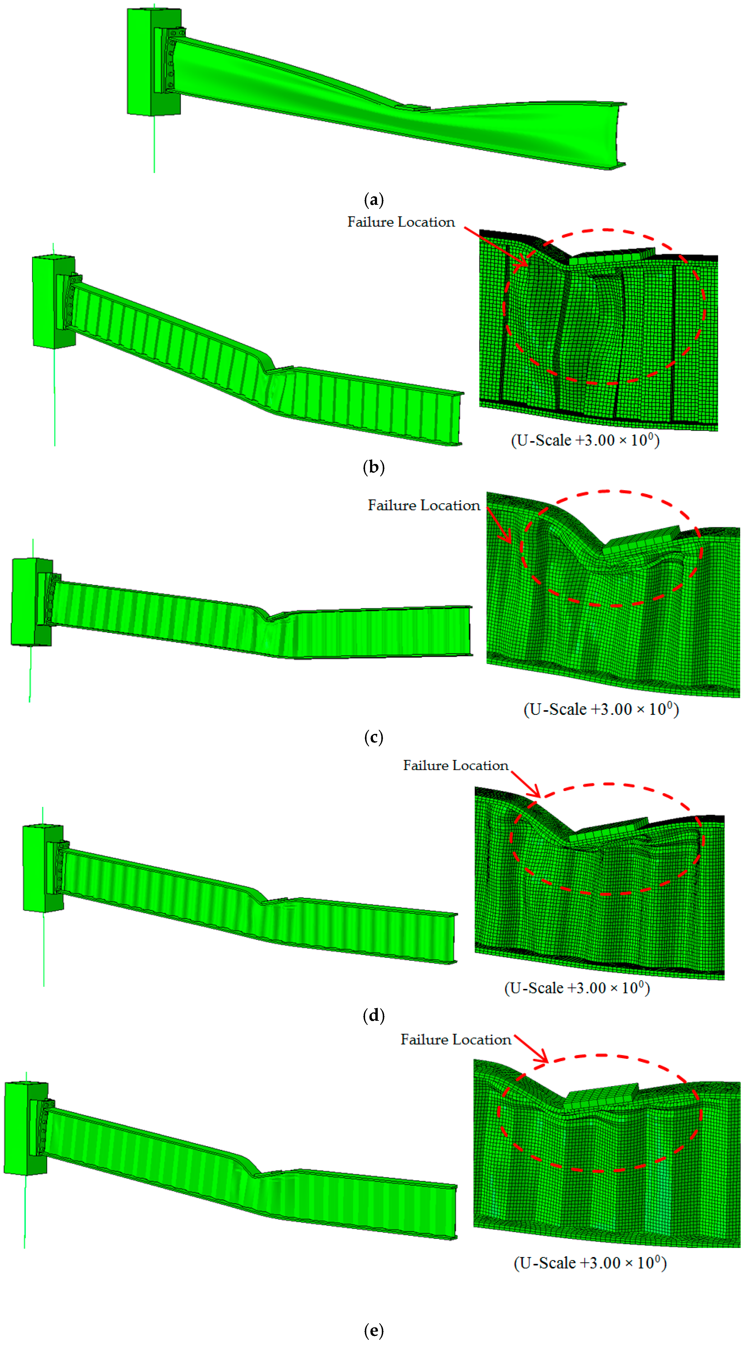
The results in Figure 16a revealed a significant effect of the flange stiffener on the failure mode for flat web beams. It is observed that a stiffener at the flange–web junction helped resist the global buckling of the web. The failure of the flat web was due to web local buckling by combined bending and shear. As shown in Figure 16b–e, there was an increase in buckling resistances of the flanges at the point load due to the flange stiffener, compared with the flanges without stiffener. The specimens of Trap, Rec, and Sin corrugations had similar failure mechanisms. In these cases, the beams failed by vertical buckling of the compression flange into the web, then the web of the beam buckled locally under compressive loads. As the beams were provided with flange stiffener at the loading point, the failure location shifted away from the point of load application to adjacent folds at maximum bending and shear. However, the beam of Tria corrugation failed by global buckling of the web away from the loading point, at the panels of maximum shear, as shown in Figure 16e. The failure mechanism of all specimens is clear as shown in Figure 17, which represents the plastic strain at failure for SBCW provided with flange stiffener.
Figure 16. Deformed shape (U) at failure for beams with stiffener (hw/tw = 250): (a) flat web; (b) Rec corrugation; (c) Trap corrugation; (d) Sin corrugation; (e) Tria corrugation.
Figure 17. Plastic strain (PEEQ) at failure for beams with stiffener (hw/tw = 250): (a) Rec; (b) Trap; (c) Sin; (d) Tria. (U-Scale +1.00 × 100).

7. Effect of Web Thickness

In the previous sections, all the simulations were at (hw/tw = 428/1.7 = 250). In this section, the effect of using different values of web thickness to the beam (hw/tw = 428/2.15 = 200) is checked. Table 8 shows a comparison of Pu for beam without and with a stiffener at hw/tw = 250 and (hw/tw = 200). Figure 18 shows the load–deflection curves for beams with flat web and different web corrugation configurations with slenderness hw/tw = 200 without and with flange stiffener, respectively. As expected, at the higher web thickness, the beam’s load-carrying capacity was higher. Furthermore, Figure 18 clearly shows the prolonged ultimate load of the beams with web corrugations compared to the flat web for beams, except for the Tria corrugation with stiffener, which gave a slight increase. However, what is more remarkable is that at higher web thickness, the beams with Sin, Rec, and Tria corrugations were able to achieve a higher increase in ultimate load than the beam with Trap corrugation. The beam applied load at failure for beams of hw/tw = 200 increased by about 22.6% and 28% when using Sin corrugations, 18.6% and 24.9% in case of Rec corrugations, 20.1 and 19.1% in case of Tria corrugations, and 11.1% and 17.7% in case of Trap corrugations, compared to beams of hw/tw = 250 without and with flange stiffener, respectively.
Table 8. A comparison of Pu for beams without and with flange stiffener at hw/tw = 250 and hw/tw = 200.
Figure 18. Load–mid-span deflection curves for beams (hw/tw = 200): (a) without stiffener; (b) with stiffener.
Figure 19, Figure 20, Figure 21 and Figure 22 show the failure modes and deformed shapes for beams of hw/tw = 200 with different web corrugation configurations without and with flange stiffener, respectively. Due to the increased web thickness, all the beams without flange stiffener failed by the same failure mode being local buckling of the web under compressive stresses at the point load after a vertical buckling of the compression flange, as shown in Figure 19 and Figure 20, whereas, for beams with flange stiffener, it was at the folds near the point load (see Figure 21 and Figure 22).
Figure 19. Deformed shape (U) at failure for beams without stiffener (hw/tw = 200) using extended endplate: (a) flat web; (b) Rec corrugation; (c) Trap corrugation; (d) Sin corrugation; (e) Tria corrugation.
Figure 20. Plastic strain (PEEQ) at failure for beams without stiffener (hw/tw = 200) using extended endplate: (a) flat web; (b) Rec corrugation; (c) Trap corrugation; (d) Sin corrugation; (e) Tria corrugation. (U-Scale +1.00 × 100).
Figure 21. Deformed shape (U) at failure for beams with stiffener (hw/tw = 200) using extended endplate: (a) flat web; (b) Rec corrugation; (c) Trap corrugation; (d) Sin corrugation; (e) Tria corrugation.
Figure 22. Plastic strain (PEEQ) at failure for beams with stiffener (hw/tw = 200) using extended endplate: (a) flat web; (b) Rec corrugation; (c) Trap corrugation; (d) Sin corrugation; (e) Tria corrugation. (U-Scale +1.00 × 100).

8. Effect of Type of Endplate Reverse Channel Connection

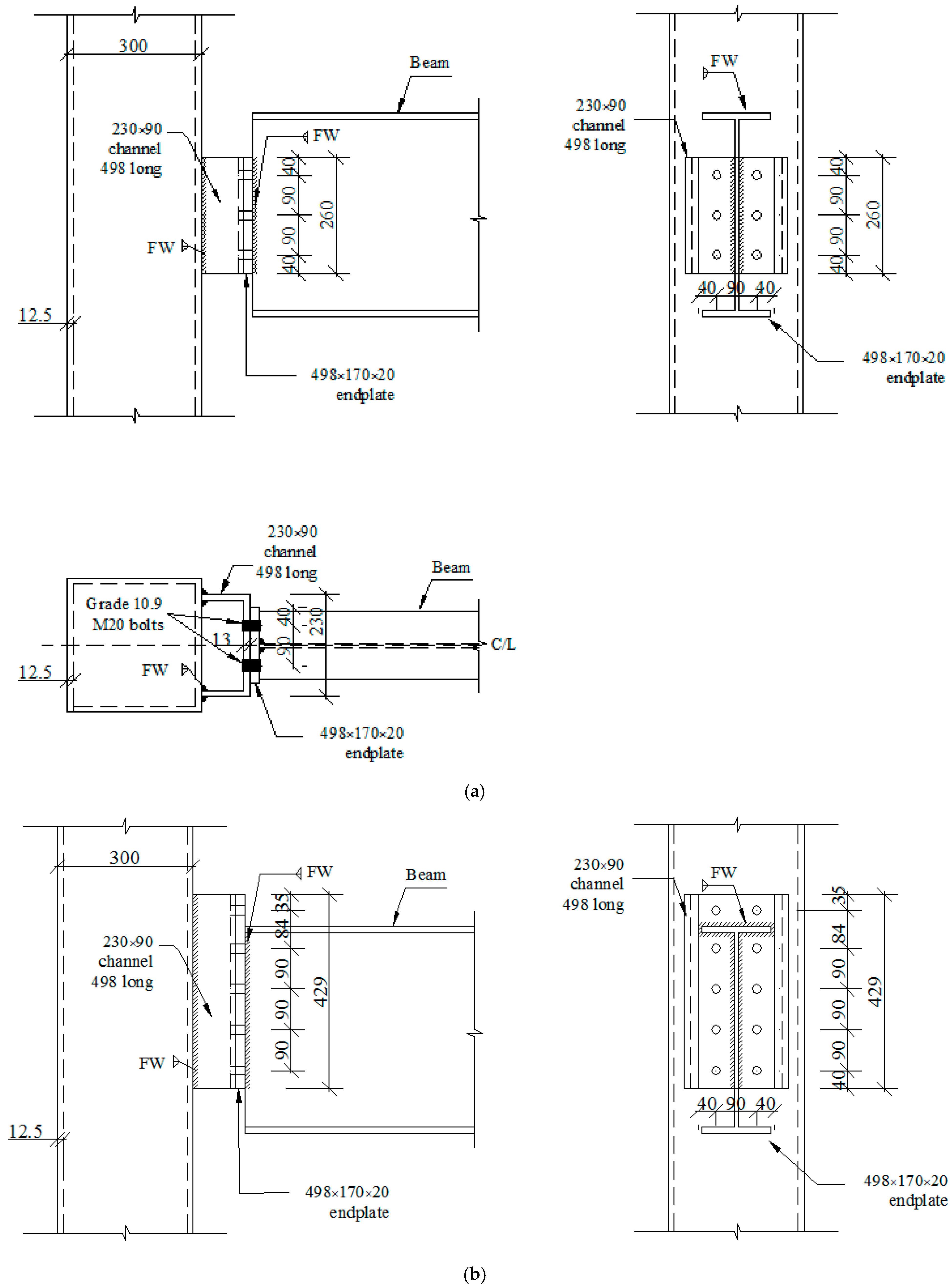
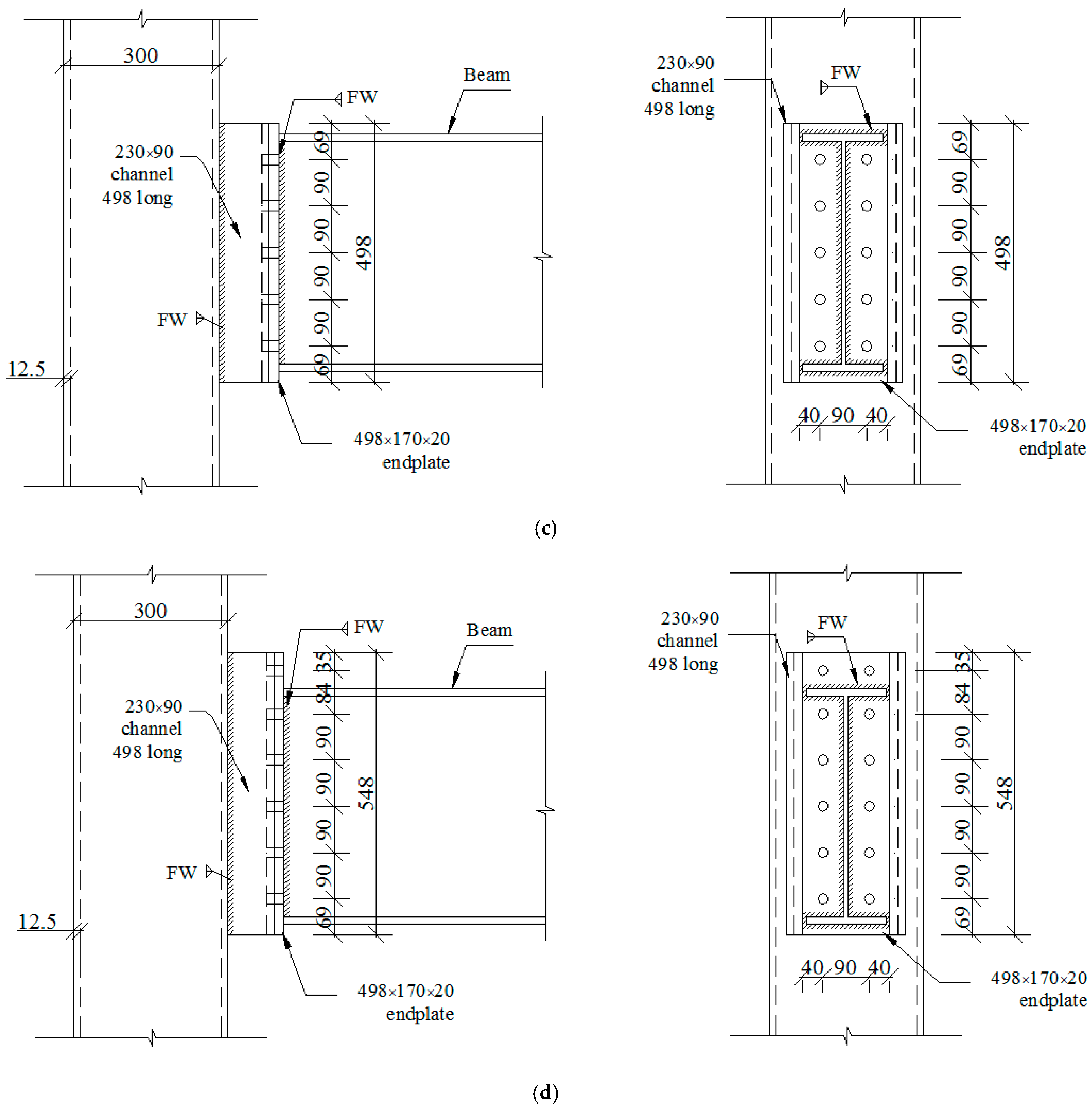
Connections between SBCW and CFTC in all previous simulations were extended end plate reverse channel connection. Different connection configurations may achieve different combinations of strength and deformation capacity and this parametric study investigated the following four configurations and their consequence on the load-carrying capacity of SBCW: flexible endplate (Figure 23a); hybrid extended/flexible endplate (Figure 23b) with a flush endplate at the top, providing tensile resistance, and flexible endplate at the bottom to enhance deformation capacity; flush endplate (Figure 23c); and extended endplate (Figure 23d). Figure 24 shows a comparison between the load–deflection results of the beams with different web corrugation profiles (Trap, Rec, Sin, and Tria) using the various types of endplate connections. All the other parameters are according to simulations in the previous section. Owing to an increase in the stiffness of the extended or flush endplate connection compared to the other joint types, the load carrying capacity of the beams connected to CFTC using extended or flush end plates exhibited higher ultimate capacities than the beams connected using hybrid extended/flexible endplate or flexible endplate, as shown in comparative bar chart in Figure 25. The increase rate (ΔPu %) depended on the web corrugation profile and ranged between (5.3–31.7%) and (25–30.9%) for the flush endplate and extended endplate, respectively, when compared to the flexible endplate, as shown in Table 9. Also, the beams connected using the extended or flush endplate connections had higher rotational stiffness than the other connections (see Figure 24).
Figure 23. Basic geometrical details of 4 configurations of reverse channel connection: (a) flexible endplate; (b) hybrid extended/flexible endplate; (c) flush endplate; (d) extended endplate.
Figure 24. Effects of joint type on beam behaviour: (a) flat web; (b) Rec corrugation; (c) Trap corrugation; (d) Sin corrugation; (e) Tria corrugation.
Figure 25. A comparison of Pu for beams using 4 configurations of reverse channel connection.
Table 9. Pu for beams using 4 configurations of reverse channel connection.
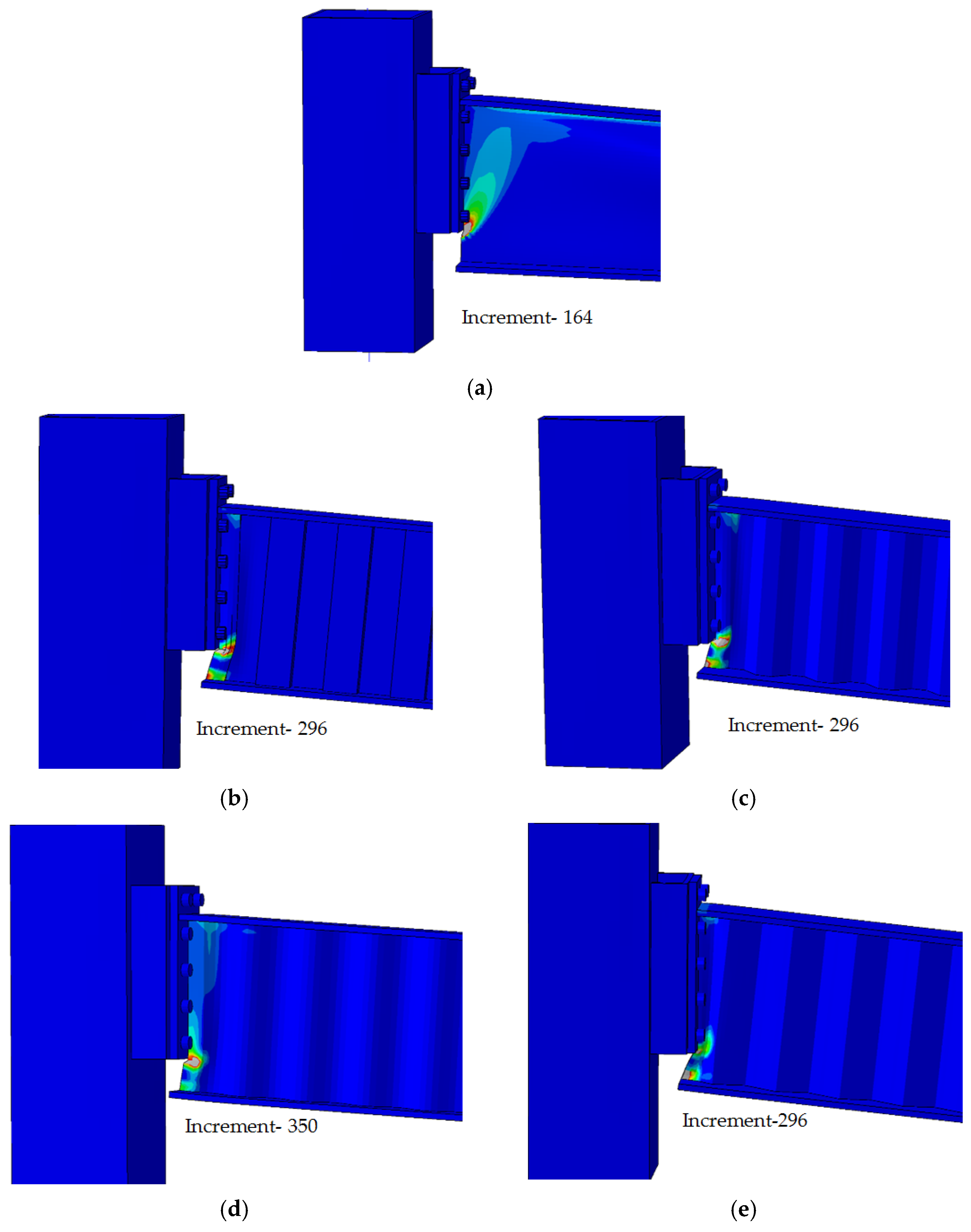
Figure 26, Figure 27, Figure 28, Figure 29, Figure 30 and Figure 31 show the failure modes and deformed shapes for beams with different web corrugation profiles (Trap, Rec, Sin, and Tria) using various types of endplate connections. As a result of the difference in strength and deformation capacity, different connection configurations failed by different failure modes. As can be seen in Figure 26 and Figure 27, due to the decreased part of the web connected to the flexible endplate, all the SBCW connected to the flexible endplate failed by web shear failure at maximum shear force. In the case of the hybrid extended/flexible endplate, the beam failed at the compression zone of the connection by a combination of shear and bending stresses, as shown in Figure 28 and Figure 29. Whereas, the observed failure mode of SBCW connected to the flush endplate was similar to the failure mode of specimens S2 of Nie et al. [], that being local shear buckling over 2 or 3 folds of the web, as shown in Figure 30 and Figure 31. However, owing to the highest stiffness and strength capacity of the extended endplate connection, the failure occurred away from the connection, and the beams failed by local buckling of the web under compressive stresses at the folds near the point load, as illustrated in Figure 21 and Figure 22 in the previous section.
Figure 26. Deformed shape (U) at failure for beams with stiffener (hw/tw = 200) using flexible endplate: (a) flat web; (b) Rec corrugation; (c) Trap corrugation; (d) Sin corrugation; (e) Tria corrugation.
Figure 27. Plastic strain (PEEQ) at failure for beams with stiffener (hw/tw = 200) using flexible endplate: (a) flat web; (b) Rec corrugation; (c) Trap corrugation; (d) Sin corrugation; (e) Tria corrugation. (U-Scale +1.00 × 100).
Figure 28. Deformed shape (U) at failure for beams with stiffener (hw/tw = 200) using hybrid extended/flexible endplate: (a) flat web; (b) Rec corrugation; (c) Trap corrugation; (d) Sin corrugation; (e) Tria corrugation.
Figure 29. Plastic strain (PEEQ) at failure for beams with stiffener (hw/tw = 200) using hybrid extended/flexible endplate: (a) flat web; (b) Rec corrugation; (c) Trap corrugation; (d) Sin corrugation; (e) Tria corrugation. (U-Scale +1.00 × 100).
Figure 30. Deformed shape (U) at failure for beams with stiffener (hw/tw = 200) using flush endplate: (a) flat web; (b) Rec corrugation; (c) Trap corrugation; (d) Sin corrugation; (e) Tria corrugation.
Figure 31. Plastic strain (PEEQ) at failure for beams with stiffener (hw/tw = 200) using flush endplate: (a) flat web; (b) Rec corrugation; (c) Trap corrugation; (d) Sin corrugation; (e) Tria corrugation. (U-Scale +1.00 × 100).

9. Limitations of the Study and Practical Implications

This study is limited by the following:
-
Elastic CFTC (concrete-filled tubular columns).
-
The SBCW overall height and flange dimensions are the same as the beam section size: 457 × 152 × 67 UB (hw = 428 mm, bf = 153.8 mm, and tf = 15 mm).
-
The web thickness: tw= 1.7 and 2.15 mm (hw/tw =250 and 200).
-
The SBCW is connected to CFTC using reverse channel end plate connections.
-
The connection is strong enough to transfer the failure to the beam (failure occurs in the beam before the connection).
-
Perfect bolt preload.
-
Ambient temperature (no elevated temperature).
-
The beam is applied by two monotonic concentrated loads (no cyclic load).
-
No residual stresses in flanges.
The following practical implications may be recommended from this study:
-
Using SBCW to increase the beam’s load capacity and enhance strength against shear buckling failure.
-
Using Rec and Trap web corrugation shapes for the beams without flange stiffener at point load.
-
Adding flange stiffener at point load for the beams of Tria and Sin web corrugation.
-
Using hw/tw = 200 for SBCW.
-
Using extended or flush endplate connections to connect SBCW to CFTC.

10. Conclusions

There were only a few research projects carried out on the performance of structural subassemblies of SBCW. The main aim of this research is to study the behaviour of structural subassemblies of steel beams with different corrugated web profiles. This research investigates the behaviour of four types of corrugation: Trap, Rec, Sin, and Tria under two-point loading. The effects of several geometric parameters were investigated namely: different web corrugation profiles, flange stiffener, and web thickness. From the results, these conclusions can be summarized:
-
The behaviour of structural subassemblies of SBCW may require further experimental and numerical investigations, including elevated temperature behaviour, dynamic behaviour under extreme conditions and multi-hazard events.
-
The proposed FE model is in good agreement with the experimental observations and results in terms of the failure mode, deformed shape, and the measured vertical deflection–relationship. The FE model clearly captured the global and local shear buckling of the trapezoidal corrugated steel web at failure.
-
The common failure mode of structural subassemblies of steel beams with different corrugated webs subjected to two-point load is the compression flange buckling vertically into the web, then local buckling of the web under compressive loads.
-
The behaviour of I-beam sections can be improved by means of the web corrugation profiles. This is reflected in reported differences for different web corrugation shapes. On the other hand, adding a flange stiffener to the corrugated web beams introduces a slight improvement. To prolong the beam’s load-carrying capacity of corrugated web beam, increasing the web thickness slenderness ratio hw/tw can be an effective solution.
-
Among the four web corrugation shapes investigated, using the Rec and Trap web corrugation shapes gave the best behaviour for the beams without flange stiffener subjected to bending moment and shear. Beams with Trap and Rec web corrugations showed an increase of 22% and 18%, respectively. Meanwhile, beams with Tria and Sin web corrugations gave the least improvement. In this case, the ultimate load increases by 10.5%.
-
Adding a flange stiffener at the point load positions exhibited a relatively slight increase in the ultimate load of the beams. However, the stiffener increased the buckling resistance of the flanges and web. The best effect of the flange stiffener was for Tria and Sin web corrugations with an increase of about 5.1% and 2.6%, respectively, compared with those without a flange stiffener.
-
The web thickness has an important influence on the structural behaviour of the corrugated web beams. The increased web thickness from hw/tw = 250 to hw/tw = 200 increased the beam load-carrying capacity of the corrugated beam differently. For Sin and Rec web corrugations, the difference in beam load-carrying capacity was 28.8% and 24.9%, respectively. Meanwhile, for the Tria web corrugation, the difference was 20.1%. Finally, the difference reached 17.7% for Trap web corrugation.
-
Among the four connection types investigated, using the extended or flush endplate connections gave the best behaviour of SBCW connected to CFTC. Using a flexible endplate (or hybrid extended/flexible endplate) connection was not effective. Extended and flush endplate connections enhanced the beam’s ultimate load and showed an increase of (5.3–31.7%) and (25–30.9%) for flush endplate and extended endplate, respectively, compared to flexile endplate, depending on the web corrugation profile.

Author Contributions

Conceptualization, S.A.E. and F.S.A.; methodology, S.A.E. and F.S.A.; software, S.A.E.; validation, S.A.E.; formal analysis, S.A.E. and F.S.A.; investigation, S.A.E. and F.S.A.; resources, S.A.E. and F.S.A.; data curation, S.A.E. and F.S.A.; writing—original draft preparation, S.A.E.; writing—review and editing, S.A.E. and F.S.A.; visualization, S.A.E. and F.S.A.; supervision, S.A.E. and F.S.A.; project administration, S.A.E. and F.S.A.; funding acquisition, S.A.E. and F.S.A. All authors have read and agreed to the published version of the manuscript.

Funding

This research received no external funding.

Data Availability Statement

The original contributions presented in this study are included in the article. Further inquiries can be directed to the corresponding author.

Acknowledgments

The authors are thankful to the Deanship of Graduate Studies and Scientific Research at the University of Bisha for supporting this work through the Fast-Track Research Support Program.

Conflicts of Interest

The authors declare no conflicts of interest.

References

  1. Al-Kannoon, M.A.; Suhiel, I.A. Experimentally flexural behaviour study of steel beams with corrugated webs. IOP Conf. Ser. Mater. Sci. Eng. 2020, 888, 12084. [Google Scholar] [CrossRef]
  2. Elamary, A.S.; Alharthi, Y.; Abdalla, O.; Alqurashi, M.; Sharaky, I.A. Failure mechanism of hybrid steel beams with trapezoidal corrugated-web non-welded inclined folds. Materials 2021, 14, 1424. [Google Scholar] [CrossRef] [PubMed]
  3. Hasan, Z.K.; Hemzah, S.A.; Al-kannoon, M.A.-A.K. Behaviour of corrugated steel compact I-section beams. In Proceedings of the 2nd International Conference for Civil Engineering Science (ICCES). J. Phys. Conf. Ser. 2021, 1895, 012063. [Google Scholar] [CrossRef]
  4. Ammash, H.K.; Al-Bader, M.A. Shear behaviour of steel girder with web-corrugated core sandwich panels. IOP Conf. Ser. Mater. Sci. Eng. 2020, 1090, 012017. [Google Scholar] [CrossRef]
  5. Landolfo, R.; Mammana, O.; Portioli, F.; Di Lorenzo, G.; Guerrieri, M.R. Laser- welded built-up cold-formed steel beams: Experimental investigations. Thin-Walled Struct. 2008, 46, 781–791. [Google Scholar] [CrossRef]
  6. Kövesdi, B.; Dunai, L. Fatigue life of girders with trapezoidally corrugated webs: An experimental study. Int. J. Fatigue 2014, 64, 22–32. [Google Scholar] [CrossRef]
  7. Anami, K.; Sause, R.; Abbas, H.H. Fatigue of web-flange weld of corrugated web girders: 1. Influence of web corrugation geometry and flange geometry on web-flange weld toe stresses. Int. J. Fatigue 2005, 27, 373–381. [Google Scholar] [CrossRef]
  8. Wang, S.; Liu, Y.; He, J.; Xin, H.; Yao, H. Experimental study on cyclic behaviour of composite beam with corrugated steel web considering different shear-span ratio. Eng. Struct. 2019, 180, 669–684. [Google Scholar] [CrossRef]
  9. Emami, F.; Mofid, M.; Vafai, A. Experimental study on cyclic behaviour of trapezoidally corrugated steel shear walls. Eng. Struct. 2013, 48, 750–762. [Google Scholar] [CrossRef]
  10. Al-Mawashee, H.S.; Al-Kannoon, M.A.-A. Flexural strength of castellated beams with corrugated webs. J. Phys. IICESAT Conf. 2021, 1973, 012213. [Google Scholar] [CrossRef]
  11. Nie, J.-G.; Zhu, L.; Tao, M.-X.; Tang, L. Shear strength of trapezoidal corrugated steel webs. J. Constr. Res. 2013, 85, 105–115. [Google Scholar] [CrossRef]
  12. Elgaaly, M.; Hamilton, R.W.; Seshadri, A. Shear strength of beams with corrugated webs. J. Struct. Eng. ASCE 1996, 122, 390–398. [Google Scholar] [CrossRef]
  13. Elgaaly, M.; Seshadri, A.; Hamilton, R.W. Bending strength of steel beams with CWs. J. Struct. Eng. ASCE 1997, 123, 772–782. [Google Scholar] [CrossRef]
  14. Elamary, A.S.; Saddek, A.B.; Alwetaishi, M. Effect of corrugated web on flexural capacity of steel beams. Int. J. Appl. Eng. Res. 2017, 12, 470–481. [Google Scholar]
  15. Khalid, Y.A.; Chan, C.L.; Sahari, B.B.; Hamouda, A.M.S. Bending behaviour of corrugated web beams. J. Materials. Process. Technol. 2004, 150, 242–254. [Google Scholar] [CrossRef]
  16. Naji, R.N.; Chkheiwer, A.H. Study on the non-linear finite element analysis of corrugated webs in steel sections with varying thickness. Int. J. Mech. Eng. 2022, 7. [Google Scholar]
  17. Li, G.-Q.; Jiang, J.; Zhu, Q. Local bucking of compression flanges of H-beam with corrugated webs. J. Constr. Res. 2015, 112, 69–79. [Google Scholar] [CrossRef]
  18. Jáger, B.; Dunai, L.; Kövesdi, B. Flange buckling behaviour of girders with corrugated web part ii: Numerical study and design method development. Thin-Walled Struct. 2017, 118, 238–252. [Google Scholar] [CrossRef]
  19. Luo, R.; Edlund, B. Ultimate strength of girders with trapezoidally corrugated webs under patch loading. Thin-Walled Struct. 1996, 24, 135–156. [Google Scholar] [CrossRef]
  20. De’nan, F.; Choong, K.; Hashim, N.S. The effects of the depth of web on the bending behaviour of triangular web profile steel beam section. AIP Conf. Proc. 2017, 1892, 020022. [Google Scholar] [CrossRef]
  21. Kumar, U.M.; Reddy, D.P.; Patel, R.R.; Pandian, M.S.; Karthikeyan, K. A study on flexural capacity of steel beams with corrugated web. Int. J. Civ. Eng. Technol. (IJCIET) 2018, 9, 945–957. [Google Scholar]
  22. Mutalib, A.A.; Mussa, M.H.; Abdulghafoor, A.M. Finite element analysis of composite plate girders with a corrugated web. J. Eng. Sci. Technol. 2018, 13, 2978–2994. [Google Scholar]
  23. Chan, C.L.; Khalid, Y.A.; Sahari, B.B.; Hamouda, A.M.S. Finite element analysis of corrugated web beams under bending. J. Constr. Steel Res. 2002, 58, 1391–1406. [Google Scholar] [CrossRef]
  24. Al-Kanon, M.A.-A.; Suhiel, I.A. Flexural behaviour of steel beam with corrugated web. Int. J. Sci. Technol. Res. 2019, 10, 3004–3009. [Google Scholar]
  25. Sayed, A.M.; Elaraki, Y.G.; Elalaoui, O. Experimental and numerical analysis of steel beams’ efficiency with different shapes of corrugated webs under free vibrations. Metals 2022, 12, 938. [Google Scholar] [CrossRef]
  26. Tohamy, A.S.; Sadeek, R.A.; Saddek, A.B.; Badran, S.F.; El-Serwi, A.A. Behaviour of trapezoidal corrugated webs girders with cutouts: Experimental and analytical solution. J. Eng. Sci. 2022, 50, 146–159. [Google Scholar]
  27. Tohamy, A.S.; Badran, S.F.; EL-Serwi, A.A.; Sadeek, R.A.; Saddek, A.B. Efficiency of web cutouts for steel plate girders with corrugated webs versus flat webs under shear loading. Artic. Arab. J. Sci. Eng. 2022, 48, 5215–5228. [Google Scholar] [CrossRef]
  28. Almohamady, A. Opening in oriented corrugated web steel beams. IOP Conf. Ser. Earth Environ. Sci. 2024, 1326, 012028. [Google Scholar] [CrossRef]
  29. Hafsamol, S.; Abraham, R. Finite element analysis of corrugated web beams, column and slab connection under loading condition. Int. Res. J. Eng. Technol. (IRJET) 2019, 06, 5418–5422. [Google Scholar]
  30. Wang, Y.C.; Xue, L. Experimental study of moment–rotation characteristics of reverse channel connections to tubular columns. J. Constr. Steel Res. 2013, 85, 92–104. [Google Scholar] [CrossRef]
  31. ABAQUS Analysis User’s Manual, Version 6.6. ABAQUS Inc.: Palo Alto, CA, USA, 2006.
  32. EN 1993-1-5:2006; Eurocode 3—Design of Steel Structures—Part 1–5: Plated Structural Elements. European Committee for Standardisation: Brussels, Belgium, 2006; pp. 1–53.
Disclaimer/Publisher’s Note: The statements, opinions and data contained in all publications are solely those of the individual author(s) and contributor(s) and not of MDPI and/or the editor(s). MDPI and/or the editor(s) disclaim responsibility for any injury to people or property resulting from any ideas, methods, instructions or products referred to in the content.

Article Metrics

Citations

Article Access Statistics

Multiple requests from the same IP address are counted as one view.