Abstract
This study examines the flexural behavior of reinforced concrete (RC) beams that utilize steel, glass fiber-reinforced polymer (GFRP), and hybrid steel–GFRP longitudinal bars. It considers variations in stirrup material (steel or GFRP) and stirrup spacing (100 mm or 200 mm). Nine beam specimens were subjected to three-point bending tests until failure. Their performance was assessed based on ultimate load, deflection, stiffness, ductility, energy absorption, and failure mode. The experimental program aimed to isolate the effects of transverse reinforcement detailing and to elucidate the role of stirrup characteristics in governing the transition between flexure and shear-controlled behavior. The findings indicated that both the type of reinforcement and the configuration of stirrups significantly influenced structural performance. Steel-reinforced beams demonstrated stable and ductile flexural behavior, whereas GFRP-reinforced beams supported loads up to 18% higher but experienced abrupt failure in brittle shear with restricted ductility. Hybrid beams effectively integrated the benefits of both materials: The HS100 specimen, which featured closely spaced steel stirrups, achieved the highest ultimate load (162.5 kN), maximum deflection (19.7 mm), and greatest energy absorption (2450 kN·mm). In contrast, beams utilizing GFRP stirrups exhibited early diagonal cracking and abrupt failure, even with closely spaced stirrups. The study indicates that hybrid steel–GFRP reinforcement can enhance the strength, ductility, and toughness of reinforced concrete beams, contingent upon the application of sufficient steel confinement. The findings provide practical recommendations for enhancing hybrid RC design by positioning steel in tension and utilizing steel stirrups for confinement, while effectively employing GFRP in compression zones or in corrosive environments.
1. Introduction
The widespread adoption of reinforced concrete (RC) structures in modern construction underscores their pivotal role in shaping the built environment. However, a critical challenge to their durability and safety lies in the susceptibility of traditional steel reinforcement to corrosion, particularly in aggressive environments. Corrosion-induced deterioration compromises structural integrity and imposes substantial maintenance costs through frequent repairs and replacements [1,2,3]. This global issue has driven the search for alternative reinforcement materials that offer superior durability and mechanical properties to extend the lifespan of RC structures [4]. Moreover, aggressive exposures expected to intensify due to climate change (e.g., elevated temperature–humidity cycles, saline intrusion, alkaline conditioning) can further accelerate degradation processes. Recent studies have demonstrated that such environments degrade composite–concrete interfaces, reducing bond capacity and altering debonding mechanisms, which reinforces the need for durable reinforcement strategies [5].
Modern concrete technology uses supplemental cementitious ingredients and innovative admixtures to improve durability and mechanical performance. Hosseinzadehfard and Mobaraki [6] found that natural pozzolans as partial replacements for microsilica improve the corrosion resistance and strain behavior of RC. These materials improve the concrete matrix and mitigate corrosion of embedded reinforcing steel. However, despite improvements in matrix durability, structural ductility remains a significant concern. Thus, this work addresses a structural gap by investigating the effects of hybrid steel–GFRP longitudinal reinforcement and varied stirrup materials and spacings affect flexural ductility and energy absorption. This comprehensive approach illuminates how reinforcement detailing can balance strength, flexibility, and corrosion resistance in next-generation concrete structures.
Fiber-reinforced polymer (FRP) materials have emerged as a promising solution, leveraging advancements in composite technologies. Among these, glass FRP (GFRP) bars have gained attention due to their exceptional corrosion resistance, high strength-to-weight ratio, and non-conductive nature. Furthermore, GFRP generally has the lowest initial cost among various FRP options, owing to its lower manufacturing cost and wider availability [7,8,9,10]. These characteristics make GFRP bars a viable alternative to conventional steel reinforcement in applications where durability is paramount [11,12,13]. As noted by Latosh et al. [14], FRPs combine strength and non-corrosive properties, offering a compelling option in scenarios where steel reinforcement is vulnerable.
Despite their advantages, GFRP bars have certain limitations that hinder their standalone application in structural systems. Most notably, their linear elastic behavior until failure results in brittle rupture without significant warning signs, unlike steel reinforcement, which provides ductility through yielding and plastic deformation [15]. Their elastic modulus is roughly one-fifth that of steel, which means that GFRP-RC beams tend to exhibit larger deflections and wider cracks under service loads compared to steel–RC beams with similar reinforcement ratios [15,16]. Experimental comparisons have shown that while GFRP-reinforced beams can achieve higher ultimate loads than identical steel-reinforced beams (due to GFRP’s high tensile strength), they fail at much lower curvatures, resulting in reduced ductility and energy absorption [10]. Elbawab et al. observed GFRP-RC beams carrying 8–18% greater peak load than steel–RC beams but with 38–58% lower deflection at failure, indicating a sudden, brittle collapse [10].
Another limitation is the behavior of GFRP bars in compression. While steel contributes in compression zones (as top reinforcement in beams or as longitudinal bars in columns), FRP bars are primarily designed for tension. GFRP can sustain compressive stress, but its compressive strength is typically only about 50–60% of its tensile strength [17,18]. The American Concrete Institute’s earlier guidance (ACI 440, 2006) recommended against the use of FRP bars in the compression zone of flexural members [19]. Although more recent research has started evaluating GFRP bars under compression loading [9,10,15,17,20,21,22,23], the available data remain limited, and design codes remain cautious. GFRP’s contribution as compression reinforcement is often neglected or assigned as a large reduction factor in design calculations [19]. This conservatism highlights a knowledge gap regarding whether GFRP bars can be effectively used in compression zones (e.g., as top bars in beams) without compromising member performance. Addressing this question is part of the motivation for exploring hybrid steel–GFRP reinforcement configurations.
Given these challenges, researchers have proposed hybrid reinforcement systems that combine both steel and GFRP bars within the same member to leverage the benefits of each material [8,15,24,25,26]. In a hybrid steel–GFRP RC beam, typically the steel bars provide ductility and yield prior to failure, while the GFRP bars provide additional tensile capacity and corrosion resistance. The optimal arrangement of hybrid bars can vary: some studies place steel and GFRP bars interspersed in the tension region, whereas others recommend placing steel in the extreme tension layer (to ensure it yields first) and GFRP in inner layers or near the top (where it can contribute to strength but is less strained). Recent experiments confirm that hybrid steel–GFRP beams can achieve a balanced performance: improved ultimate strength over steel-only beams due to the GFRP’s high tensile capacity, yet significantly better ductility and stiffness than GFRP-only beams due to the presence of steel [15]. Experimental programs consistently show that hybrid steel–FRP systems recover ductility and service stiffness relative to FRP-only beams while maintaining higher strength than steel-only controls. Reviews and data compilations since 2010 report improved load–deflection shape and refined cracking when a yielding steel component is present [27]. Beyond experimental tests, numerical models for hybrid FRP/steel RC (e.g., sectional analysis and curvature-based predictions) capture the observed increases in moment capacity, reduced service deflection, and balanced post-cracking stiffness, providing predictive support to the hybrid concept used here [28]. These findings suggest that a properly designed hybrid beam can avoid the brittle failure mode that observed in GFRP-RC, making hybrid reinforcement a promising design strategy for durable yet ductile concrete members. Studies have further indicated that if steel yields prior to GFRP rupture, the hybrid beam’s ductility can exceed that of an equivalent all-steel beam, and the minimum required GFRP ratio could potentially be reduced by 25% without loss of safety [9].
While hybrid flexural reinforcement has gained attention, there remains a lack of data on hybridizing the transverse reinforcement or other configurations. Transverse reinforcement (stirrups) made of GFRP have been employed in some studies to address corrosion in stirrups (which are especially vulnerable, being near the concrete surface). Standards like ACI 440.1R-15 [29] permits GFRP stirrups but requires strength and development length considerations because GFRP does not yield [12]. Research shows mixed outcomes for GFRP stirrups: they provide adequate shear strength if sufficiently close-spaced, but their linear elastic behavior often results in less ductile shear failure modes. In shear tests, Zhao et al. conducted shear tests on concrete beams with GFRP stirrups and found that increasing stirrup spacing from 100 mm to 200 mm led to a drastic drop in shear capacity (nearly 45% reduction) and a shift from flexural to brittle shear failure [30]. Furthermore, beams with GFRP stirrups experienced larger deflections and crack widths at comparable loads than beams with steel stirrups. Another study reported that replacing steel stirrups with GFRP stirrups could reduce the ultimate load by approximately 8–27%, depending on the stirrup ratio, due to the lack of ductile tie action [31]. These results underline that stirrup material and spacing are crucial for structural performance, insufficient or non-ductile shear reinforcement can trigger premature diagonal-cracking failure, especially in GFRP-reinforced members. To date, however, most investigations to date have concentrated either on longitudinal hybrid reinforcement or on FRP stirrups in all-GFRP RC beams, but rarely both together.
These observations highlight knowledge gaps in knowledge regarding the combined use of hybrid flexural bars and various stirrup strategies. Real structural members may benefit from a comprehensive hybrid approach, for example, using steel where ductility is essential (tension zones, critical shear regions) and GFRP where durability is crucial (compression zones, secondary reinforcement, or stirrups in corrosive settings). Yet, the interactive effects of these choices on overall beam behavior are not fully understood. This study aims to fill that gap by investigating RC beams with hybrid steel–GFRP longitudinal reinforcement under various transverse reinforcement scenarios. Specifically, the novelty of this research lies in examining: (1) hybrid bar configurations, steel and GFRP bars combined within the beam’s cross-section, and quantifying their flexural performance relative to purely steel- or purely GFRP-reinforced beams; (2) stirrup material effect, directly comparing steel vs. GFRP stirrups in otherwise identical beams, to assess how GFRP stirrups influence shear capacity, deflection, and failure mode; and (3) stirrup spacing effect, two spacings (100 mm and 200 mm) are tested to observe how closely spaced vs. widely spaced transverse reinforcement interacts with the different longitudinal reinforcement types. By testing nine beams that systematically vary these parameters, this work aims to provide a more comprehensive picture of how hybrid reinforcement systems behave under flexural loading.
2. Research Significance
The findings of this study will extend the current state of knowledge on steel–GFRP hybrid RC beams, offering practical insights for design and construction. If hybrid beams can exhibit superior strength while maintaining ductility, they could encourage wider adoption of GFRP bars in structures that demand both durability and toughness (e.g., bridges in harsh climates, coastal structures, etc.). Moreover, understanding the limitations of GFRP stirrups will inform design guidelines, for instance, the results may support recommendations to use steel stirrups for confinement even when using GFRP main bars, or to greatly reduce stirrup spacing if using GFRP, consistent with recent conclusions in the literature. Overall, this research addresses the twin challenges of corrosion resistance and structural ductility by leveraging a hybrid reinforcement approach and provides experimental data that can feed into the next generation of design codes to safely implement GFRP materials in critical load-bearing members.
3. Materials and Methodology
3.1. Material Properties
3.1.1. Reinforcing Bars
Tensile tests were performed on both steel and GFRP reinforcing bars to determine their mechanical properties. The tests followed ASTM A615 [32] for steel and ASTM D7957 [33] for GFRP. Steel specimens (SABIC–Hadeed, Al-Jubail Industrial City, Saudi Arabia) with a nominal diameter of 12.7 mm were prepared, each cut to a length of 250 ± 1 mm [34]. GFRP bars, supplied by IKK Mateenbar Co., Dammam, Saudi Arabia [35], were tested with a nominal diameter of 12.7 mm, with each specimen cut to a length of 1000 ± 1 mm. To ensure proper load transfer during testing, the GFRP specimens were prepared in accordance with ASTM D7205 [36]. Each bar end was embedded in a steel tube with an internal diameter of 33.5 mm and a length of 330 mm, filled with a high-strength non-shrink grout (SikaGrout-114 SA, Sika AG, Baar, Switzerland). This anchorage system provided effective stress transfer between the bar and the testing apparatus. The ends of the tubes were sealed with polyvinyl chloride plugs and fitted with threaded steel bushings to enable secure gripping by the testing machine. The properties of the steel and GFRP bars, as provided in the suppliers’ data sheets, are listed in Table 1.

Table 1.
Properties of steel and GFRP bars, as provided in the suppliers’ data sheets.
All tensile tests were conducted on a universal testing machine (UTM) with a load capacity of 100 kN. Steel specimens were mounted with standard wedge-action grips, whereas the GFRP specimens were secured through the prepared anchorage system, as illustrated in Figure 1. Tests were displacement-controlled at a constant loading rate of 4 mm/min, as recommended by relevant standards and literature. This approach ensured stable axial loading and accurate characterization of the tensile behavior of both steel and GFRP bars. The tensile properties of reinforcing steel and GFRP bars were evaluated, and the results are illustrated in Figure 2. The reinforcing steel bars exhibited yield strengths consistently higher than the nominal value of 420 MPa, with an average measured yield strength of approximately 505 MPa and an ultimate tensile strength of about 604 MPa. These values meet the requirements of ASTM A615 [32], confirming the structural adequacy of the tested bars. The stress–strain behavior (Figure 2) followed the characteristic profile of ductile reinforcing steel: an initial linear-elastic region up to yielding, a distinct yield plateau, strain hardening leading to the ultimate tensile strength, and finally strain softening accompanied by localized necking before rupture. This sequence reflects the expected ductile failure mode of steel, providing significant energy absorption and deformation capacity. In contrast, the GFRP bars displayed a markedly different response. As shown in Figure 2, the stress–strain curve remained linear up to failure, with no yield plateau or strain-hardening phase. The tested GFRP specimens achieved an average ultimate tensile strength of approximately 930 MPa and a corresponding ultimate strain of about 0.02, with minimal variation among samples. Failure occurred in a brittle manner at peak load, characterized by rapid fiber rupture and matrix cracking. Unlike steel, which yields and provides deformation capacity before fracture, GFRP bars failed suddenly without prior plastic deformation.
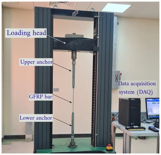
Figure 1.
Experimental setup for tensile testing of GFRP bars using the UTM.
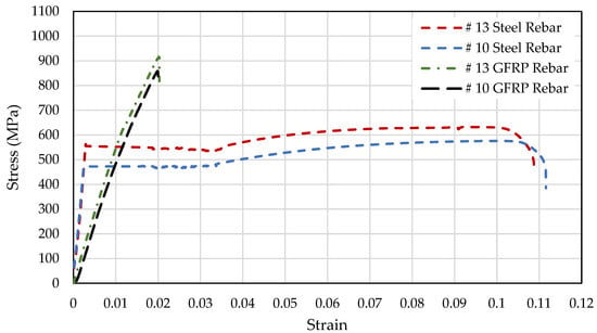
Figure 2.
Stress–strain behavior of steel and GFRP bars.
3.1.2. Concrete
All concrete specimens used in this study were cast from a single homogeneous batch to maintain consistency in material properties. The mix was proportioned to achieve an average 28-day compressive strength of 25 MPa. The proportions of cement, aggregates, water, and admixtures are summarized in Table 2. Cylindrical specimens measuring 150 mm in diameter and 300 mm in height were prepared for both compressive and splitting tensile strength testing. Tests were conducted in accordance with ASTM C39 [37] for compressive strength and ASTM C496 [38] for splitting tensile strength, using a 3000 kN compression testing machine equipped with standard platens. Compressive strength tests were carried out under force-controlled loading, applying axial load at a rate of 0.25 ± 0.05 MPa/s. To monitor strength development over time, tests were performed at curing ages of 7, 14, and 28 days. Splitting tensile strength tests were conducted on companion cylinders to evaluate the indirect tensile capacity of the concrete.

Table 2.
Concrete mixture proportions.
The mechanical properties of the concrete mix were evaluated at 28 days through standard compressive and splitting tensile strength tests on cylindrical specimens. Two cylinders, each measuring 150 mm in diameter and 300 mm in height, were tested after standard laboratory curing. The results showed an average compressive strength of 25.45 MPa, confirming that the mix achieved the target design strength. The corresponding splitting tensile strength was 3.05 MPa, which is consistent with the expected tensile-to-compressive strength ratio for normal-strength concrete. These values indicate that the concrete used in beam fabrication exhibited uniform and reliable performance at 28 days, providing a suitable matrix for evaluating the contribution of steel, GFRP, and hybrid reinforcement systems under flexural loading.
3.2. Specimen Preparation
An experimental program was conducted on nine RC beam specimens to evaluate their flexural performance under static loading. The primary objective was to investigate the structural behavior of beams reinforced with different combinations of steel and GFRP bars, as well as the influence of stirrup type and spacing. The reinforcement configurations are summarized in Table 3 and illustrated in Figure 3. Each beam had a 210 mm × 210 mm cross-section and a total length of 1100 mm. The span between supports measured 900 mm. The effective depth, accounting for a 10 mm concrete cover, #10 stirrups (10 mm), and #13 longitudinal bars (12.7 mm), was approximately 184 mm. The shear span (a) measured 450 mm, resulting in a shear span-to-depth ratio (a/d) of approximately 2.45. The test matrix included one plain concrete beam (P) without reinforcement, serving as a control specimen. Two beams (S100 and S200) were reinforced exclusively with steel longitudinal bars and steel stirrups spaced at 100 mm and 200 mm, respectively. Another two specimens (G100 and G200) were reinforced entirely with GFRP bars, including longitudinal reinforcement and stirrups, with the same stirrup spacings of 100 mm and 200 mm. Four hybrid beams were also prepared: HS100 and HS200 contained alternating steel and GFRP longitudinal bars with steel stirrups at 100 mm and 200 mm spacing, respectively, while HG100 and HG200 incorporated the same longitudinal arrangement but with GFRP stirrups. All longitudinal reinforcement consisted of #13 bars, while #10 bars were used for stirrups.

Table 3.
Summary of reinforced concrete beam specimens.
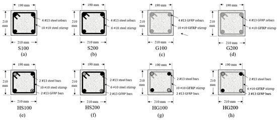
Figure 3.
Reinforcement configuration of RC specimens. (a) S100: 4 #13 steel bars; #10 steel stirrups at 100 mm. (b) S200: 4 #13 steel bars; #10 steel stirrups at 200 mm. (c) G100: 4 #13 GFRP bars; #10 GFRP stirrups at 100 mm. (d) G200: 4 #13 GFRP bars; #10 GFRP stirrups at 200 mm. (e) HS100: hybrid steel–GFRP bars; #10 steel stirrups at 100 mm. (f) HS200: hybrid steel–GFRP bars; #10 steel stirrups at 200 mm. (g) HG100: hybrid steel–GFRP bars; #10 GFRP stirrups at 100 mm. (h) HG200: hybrid steel–GFRP bars; #10 GFRP stirrups at 200 mm.
3.3. Test Setup and Instrumentation
Flexural testing of the RC beams was performed using a three-point bending configuration. Each beam specimen was placed on a loading frame with simple support, providing a clear span of 900 mm between the support centers, as illustrated in Figure 4. The load was applied at midspan through a hydraulic actuator, ensuring symmetric loading across the specimen’s cross-section. Steel rollers were used at the supports and at the loading point to minimize friction and allow free rotation, thereby simulating simply supported boundary conditions. The applied load was measured directly from the load cell integrated into the testing machine, and the vertical deflection at midspan was continuously recorded using a linear variable differential transformer (LVDT). The LVDT was fixed to a rigid frame independent of the test machine to eliminate extraneous deformations, as shown in Figure 5. The three-point bending structure was chosen to concurrently produce maximum moment and shear at mid-span, enabling assessment of how stirrup material and spacing on the transition between flexure and shear-controlled behavior. Crack initiation and propagation were monitored visually throughout testing. A crack width microscope was employed to measure crack widths at key load intervals, while photographs were taken at each significant load stage to document crack patterns and failure progression. The load and deflection data were synchronized through a digital data acquisition system (DAQ), enabling real-time recording of the structural response of each beam up to failure.
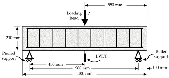
Figure 4.
Schematic of flexural test setup.
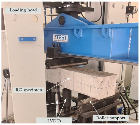
Figure 5.
Experimental setup showing loading head, RC specimen, LVDTs, and roller supports.
4. Results and Discussion
4.1. Failure Modes
The failure patterns of the nine tested beams were significantly affected by the type of longitudinal reinforcement, stirrup material, and stirrup spacing. Representative crack distributions are shown in Figure 6. The plain concrete beam (P) experienced a sudden brittle failure, marked by a single vertical mid-span crack that propagated rapidly through the depth once the tensile strength of the concrete was exceeded. No post-cracking resistance was observed. Beams reinforced with steel bars (S100 and S200) showed typical ductile flexural behavior. Multiple flexural cracks developed along the span and gradually widened before merging at mid-span. S100, with closer stirrup spacing, demonstrated improved crack control and ultimately failed by concrete crushing in the compression zone. S200 showed fewer but wider cracks and experienced a slightly earlier loss of ductility, indicating reduced confinement resulting from its wider stirrup spacing. Beams reinforced with GFRP bars (G100 and G200) carried higher loads than the steel-only beams but failed in a brittle manner. G100 displayed limited flexural cracking followed by abrupt diagonal cracking, while G200 experienced pronounced shear cracks extending toward the supports, confirming a shear-dominated failure. The absence of yielding and the lower elastic modulus of GFRP resulted in limited energy dissipation and abrupt rupture.
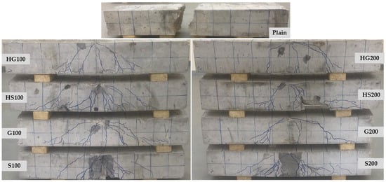
Figure 6.
Failure modes of plain, steel, GFRP, and hybrid reinforced concrete beams.
The hybrid beams with steel stirrups (HS100 and HS200) highlighted the benefits of combining materials. HS100 achieved the most favorable performance, with well-distributed flexural cracks and a ductile failure mode controlled by steel yielding and subsequent concrete crushing. The better-confined hybrid beams showed more distributed flexural cracking with smaller crack widths, consistent with reported serviceability benefits of FRP–steel hybrids [27]. Conversely, HS200 suffered from premature diagonal cracking and brittle shear failure due to the increased stirrup spacing, despite its hybrid configuration. Finally, beams reinforced with hybrid longitudinal bars and GFRP stirrups (HG100 and HG200) consistently exhibited the weakest performance. Both beams failed suddenly in shear, as indicated by steep diagonal cracks and minimal flexural cracking. Even at 100 mm spacing, GFRP stirrups (HG100) were unable to provide sufficient shear resistance, while HG200 failed even more abruptly at lower load and deflection. These observations confirm that ductility and stable failure modes are achieved only when steel stirrups are employed, while GFRP stirrups compromise shear resistance regardless of spacing. Furthermore, the superior performance of HS100 emphasizes that a well-detailed hybrid arrangement can balance strength, toughness, and durability.
4.2. Load–Deflection Behavior
The load–deflection responses of the tested beams are presented in Figure 7. Distinct differences in behavior were observed depending on reinforcement type, stirrup material, and stirrup spacing. The control specimen (P) displayed an almost linear response up to failure, accompanied by a minimal ultimate deflection, which confirms the brittle nature of unreinforced concrete. The steel-reinforced beams (S100 and S200) exhibited the classic behavior characteristic of reinforced concrete. Both specimens exhibited an initial linear elastic phase followed by yielding of the longitudinal bars and significant post-yield deformation. S100, featuring closely spaced stirrups, demonstrated higher stiffness and more gradual softening, while S200 showed a slight reduction in post-yield ductility due to wider stirrup spacing. The GFRP-reinforced beams (G100 and G200) exhibited higher load-carrying capacity compared to the steel beams, reflecting the superior tensile strength of GFRP. However, their load–deflection curves remained linear until failure, with no yielding or post-yield plateau. The absence of ductility resulted in sudden strength loss of strength after reaching the peak load, particularly in G200 which had wider stirrup spacing. This linear response followed by an abrupt post-peak drop aligns with the expected behavior of FRP-RC flexural members and accounts for the larger service deflections and crack widths relative to steel-reinforced beams. This linear-elastic response with larger service deflections/crack widths and abrupt post-peak drop is the characteristic pattern for GFRP-RC flexural members, as emphasized by ACI 440.1R-15 and practitioner summaries [29].
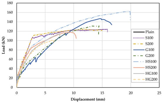
Figure 7.
Load–deflection behavior of plain, steel, GFRP, and hybrid reinforced beams.
Hybrid beams that combine steel and GFRP reinforcement, specifically HS100 and HS200, demonstrated mixed characteristics. The HS100, which features closer steel stirrups, exhibited the most favorable response, effectively combining the ductility of steel with the high tensile resistance of GFRP. Its load–deflection curve revealed a gradual reduction in stiffness, yielding, and a significant deformation capacity prior to crushing. Xiao et al. [39] noted a three-stage load–deflection response with post-yield hardening, as well as increased capacity and energy with higher hybrid ratios or thicker FRP jacket; HS100 displayed similar staged behavior, characterized by stable post-cracking stiffness, large deformation capacity, and the highest ultimate load, supporting the hybrid mechanism. This staged post-cracking response indicates that adequate transverse confinement-maintained flexure-controlled behavior and permitted significant deformation before crushing. In contrast, HS200 which has with wider stirrup spacing, exhibited a less stable response, characterized by a sharp decline in load capacity following cracking and an earlier onset of shear-related instability. The earlier drop in load capacity reflects a reduction in effective transverse reinforcement and the initiation of diagonal tension that governs the response. A nonlinear finite element (FE) parametric study indicates that increasing GFRP-stirrup spacing 50 mm to 100 mm broadens flexural cracks, decreases stiffness and ductility, and shifts response toward shear-sensitive failure. This is consistent with the observations made in the HS100, HS200, and G200 beams in this study [16]. The sensitivity of hybrid flexural performance to density transverse reinforcement aligns with prior findings that insufficient stirrup confinement limits the development of hybrid ductility and post-peak stability [39]. The hybrid beams with GFRP stirrups namely (HG100 and HG200) exhibited the least desirable performance. Their load–deflection curves indicated limited ductility and abrupt failure, which reflects inadequate shear resistance. Even with closer stirrup spacing in HG100, the response was brittle and lacked a post-cracking plateau. With GFRP stirrups the response remained linear until an abrupt failure occurred, signifying limited shear reserve and crack restraint.
The identified failure mechanisms and load–deflection characteristics align with other studies on hybrid and FRP-reinforced beams. Xiao et al. [39] and Elbawab et al. [10] noted that sufficient steel confinement enables staged stiffness degradation and a pseudo-ductile flexural response, akin to the HS100 beam examined in this investigation. Conversely, beams including GFRP stirrups or broader spacing demonstrated brittle shear failure, aligning with the results of Oukaili et al. [31]. This agreement indicates that transverse reinforcement detailing, rather than the composition of longitudinal bars, predominantly influences the transition from flexure-dominated to shear-dominated behavior.
4.3. Ultimate Load Capacity
The ultimate load capacities of the tested beams varied significantly depending on reinforcement type, stirrup material, and stirrup spacing, as illustrated in Figure 8. The control beam (P) reached the lowest ultimate load of 22.0 kN, failing abruptly once the concrete tensile capacity was exceeded. Stirrup detailing significantly affected the flexural–shear interaction and ultimate load capacity (Figure 8). Beams with 100 mm steel stirrup spacing (HS100, S100) showed better confinement, delayed cracking, and full reinforcement mobilization. Conversely, beams with GFRP stirrups or 200 mm spacing exhibited reduced restraint, premature diagonal cracking, and shear-controlled failure. The lower stiffness and non-yielding nature of GFRP stirrups further limited dowel action and anchorage. Therefore, stirrup material and spacing strongly influenced the load capacity of hybrid and GFRP-reinforced beams. These results confirmed the limited structural capacity of plain concrete under flexural loading and established a baseline for comparison with reinforced specimens. The steel-reinforced beams (S100 and S200) achieved ultimate loads of approximately 124 kN, nearly six times the control specimen. The close agreement between the two beams indicated that longitudinal steel reinforcement governed strength, while stirrup spacing had only a minor effect on ultimate capacity. Beams reinforced exclusively with GFRP bars (G100 and G200) exhibited even higher ultimate loads, reaching 146.8 kN and 131.2 kN, respectively. This increase reflected the high tensile capacity of GFRP, though it was accompanied by brittle failure modes. The reduction observed in G200 compared with G100 highlights the adverse influence of wider stirrup spacing on load capacity when GFRP is used for both longitudinal and transverse reinforcement.
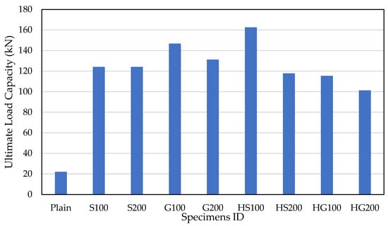
Figure 8.
Ultimate load capacities of plain, steel, GFRP, and hybrid reinforced beams.
Hybrid beams reinforced with both steel and GFRP longitudinal bars displayed contrasting results depending on stirrup type. HS100, combined hybrid longitudinal reinforcement with steel stirrups at 100 mm spacing, attained the highest ultimate load of 162.5 kN, demonstrating the beneficial synergy between steel ductility and GFRP tensile strength. Conversely, HS200, with steel stirrups at 200 mm spacing, failed earlier at 117.8 kN, highlighting the need for adequate transverse reinforcement in mobilizing the full flexural potential of hybrid beams. Hybrid beams with GFRP stirrups (HG100 and HG200) recorded the lowest load capacities among reinforced specimens, reaching only 115.3 kN and 101.3 kN, respectively. Their poor performance highlights the limited shear resistance of GFRP stirrups and their limited capacity to sustain ultimate strength levels comparable to beams with steel stirrups. Under three-point bending, the ultimate load results from the combined effects of flexural strength, governed mainly by the longitudinal reinforcement and the section’s bending resistance, and the stirrup-provided shear resistance and transverse confinement. Steel stirrups at 100 mm provide a higher effective transverse reinforcement index, tighter crack restraint, and more reliable anchorage and dowel action. Consequently, flexure governed, and the hybrid system mobilized the ductile response of steel together with the high tensile strength of GFRP, as observed for HS100. When the stirrups are GFRP, or when spacing is increased to 200 mm, the effective transverse reinforcement is reduced, diagonal tension initiates earlier, and the ultimate load becomes limited by shear rather than flexure, as reflected in HS200 and the HG series. This mechanism outlines the ranking of capacities: HS100 is the highest, followed by G100, G200, S100, and S200. The lowest rankings are HS200, HG100, and HG200. The differences arise primarily from the level of shear confinement rather than from the longitudinal reinforcement alone. This capacity drop is consistent with Xiao et al. [39] observation that all-GFRP beams tend to shear-dominated failure, while hybrid/steel beams reach flexural crushing, underscoring the role of stirrup confinement in realizing hybrid capacity and ductility.
In summary, the results show that ultimate load capacity is maximized in hybrid beams with close-spaced steel stirrups (HS100), while beams with GFRP stirrups (HG-series) exhibited the weakest performance. These findings emphasize that both reinforcement composition and stirrup detailing play critical roles in determining ultimate strength. The experimental data corroborates the central conclusion of Xiao et al. [39] that hybrid longitudinal reinforcement systems (steel + FRP) can deliver pseudo-ductile flexural performance and attain higher ultimate capacity than steel-only or GFRP-only beams. This study further demonstrates that the strength and ductility gains from hybrid reinforcement depend critically on transverse reinforcement details. With adequate steel stirrups (100 mm) spacing, the hybrids achieved ductility comparable to that reported by Xiao et al. [39]. In contrast, using GFRP stirrups or increasing the stirrup spacing to 200 mm led to an earlier shear-dominated failure, which suppressed the hybrid system’s ductility.
4.4. Deflection and Ductility
The ultimate midspan deflections of all tested beams are presented in Figure 9. The plain control specimen exhibited negligible deformation capacity, failing suddenly at only 0.18 mm of deflection. This brittle response reflects the lack of reinforcement and confirms the benchmark role of the control beam. The steel-reinforced beams (S100 and S200) displayed substantial deflections at failure, around 15–16 mm, which confirms their ductile behavior. The closer stirrup spacing in S100 promoted finer crack distribution and slightly higher deformation before crushing compared to S200. The GFRP-reinforced beams (G100 and G200) sustained higher ultimate loads but exhibited limited ductility compared with steel beams. G100 reached about 16 mm deflection, while G200 failed earlier at approximately 14 mm, illustrating the negative impact of wider stirrup spacing. The absence of yielding in GFRP bars resulted in a sudden collapse following peak load.
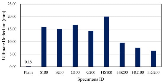
Figure 9.
Ultimate deflections of plain, steel, GFRP, and hybrid reinforced beams.
Hybrid beams with steel–GFRP longitudinal reinforcement and steel stirrups showed varied performance based on stirrup detailing. HS100 demonstrated the highest deformation capacity in the series, achieving about 20 mm of deflection. This highlights the beneficial synergy of steel ductility and GFRP strength when adequate shear resistance was provided. In contrast, HS200 failed at around 10 mm of deflection, confirming that insufficient transverse reinforcement limited ductility despite the hybrid reinforcement. Hybrid beams with GFRP stirrups (HG100 and HG200) performed the worst in terms of deflection capacity, failing at 7.6 mm and 6.4 mm, respectively. Both displayed abrupt shear failure modes, with minimal post-cracking deformation, underscoring the inability of GFRP stirrups to provide ductile shear resistance. Overall, the results indicate that ductility was maximized in HS100 due to the combined effects of steel yielding and GFRP tensile resistance, whereas the beams with GFRP stirrups (HG series) exhibited the lowest ductility and the most brittle responses.
4.5. Energy Absorption and Toughness
The energy absorption capacities of the tested beams, represented as the area under their load–deflection curves, are illustrated in Figure 10. Ductility and energy indices were evaluated using the displacement ductility ratio (μΔ = Δu/Δy), while the total absorbed energy (U) was calculated from the load–deflection data. The yield displacement (Δy) was determined through a bilinear equal-energy idealization, while the ultimate displacement (Δu) was defined as occurring at 80% of the peak load on the descending branch. Energy absorption (U) was calculated through trapezoidal integration of the recorded load–deflection curve up to Δu, utilizing raw data sampled at 10 Hz. These definitions establish a consistent framework for the comparison of ductility and toughness among steel, GFRP, and hybrid beams. This parameter reflects each specimen’s toughness and its capacity to dissipate energy before failure. The plain control beam absorbed almost no energy, failing abruptly upon cracking. This behavior underscores the inability of unreinforced concrete to withstand sudden fracture or sustain deformation. The steel-reinforced beams (S100 and S200) absorbed significantly more energy, with values ranging from 1600 to 1700 kN·mm. The close agreement between these two indicates that stirrup spacing had only a minor effect on toughness when steel reinforcement governed flexural behavior. In contrast, GFRP-reinforced beams (G100 and G200) absorbed less energy than their steel counterparts, despite exhibiting higher ultimate strength. Both specimens displayed brittle failures with limited deformation capacity, restricting their toughness to approximately 1300 to 1400 kN·mm. This observation confirms that the absence of yielding in GFRP bars constrains energy dissipation even when ultimate load capacity is high.
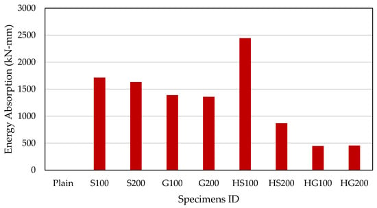
Figure 10.
Energy absorption of plain, steel, GFRP, and hybrid reinforced beams.
The hybrid beams featuring steel–GFRP longitudinal reinforcement and steel stirrups displayed the most notable differences. HS100 achieved the highest toughness of all specimens, approximately 2450 kN·mm. Its performance clearly illustrates the synergistic combination of steel ductility and GFRP tensile strength, supported by adequate shear reinforcement. In contrast, HS200 absorbed only around 900 kN·mm due to premature shear failure caused by widely spaced stirrups, preventing full flexural behavior from developing. The hybrid beams with GFRP stirrups (HG100 and HG200) recorded the lowest toughness among reinforced specimens, absorbing less than 600 kN·mm. Both beams failed suddenly in shear, exhibiting minimal energy dissipation. Even with closer spacing in HG100, the inability of GFRP stirrups to yield significantly limited toughness. In summary, HS100 absorbed nearly 40% more energy than steel-only beams and over four times that of the HG-series, highlighting the critical role of stirrup material and spacing in influencing toughness. These findings emphasize the importance of employing steel stirrups in hybrid reinforcement systems, particularly when ductility and energy absorption are critical design requirements. Energy absorption followed the same confinement hierarchy: close-spaced steel stirrups generated the highest energy absorption, while wider spacing and GFRP stirrups reduced energy due to earlier shear control.
The superior performance of hybrid beams with steel stirrups (HS100) can be attributed to the combined effects of yielding steel, which redistributes internal stresses after cracking, and the high tensile strength of GFRP bars, which can sustain additional load beyond the yield point of steel. This tension stiffening effect delays the widening of cracks and enhances both toughness and ductility. In contrast, the linear-elastic behavior of GFRP stirrups limits shear restraint and inhibits stress redistribution, leading to abrupt diagonal cracking once the tensile strength of the concrete is exceeded. These mechanisms are consistent with analytical models and experimental observations reported by Xiao et al. [39] and Dziomdziora & Smarzewski [27], confirming that the synergy between hybrid reinforcement and steel confinement plays a crucial role in determining load capacity and the post-cracking response.
4.6. Crack Width and Crack Distribution
After testing failure, each beam was examined to document its cracking behavior. For each specimen, the maximum flexural crack width, average crack spacing, and the number of cracks along the constant-moment region were recorded. Crack widths were measured using a handheld crack microscope, while crack spacing and crack count were obtained from post-test crack maps. These measurements illustrate how the different reinforcement layouts (all-steel, all-GFRP, and hybrid steel–GFRP) influenced damage localization, crack control, and stress redistribution in flexure. Table 4 summarizes the experimentally observed cracking characteristics for all beams.

Table 4.
Measured crack characteristics of tested beams.
Distinct differences in cracking response were observed among the various reinforcement systems. The steel-reinforced beams (S100 and S200) developed the largest maximum crack widths, measuring 1.77 mm and 2.07 mm, respectively. Although these beams exhibited closely spaced cracks (ranging from 70 to 90 mm) and a relatively high number of cracks (between 9 and 10), the localized yielding of the steel reinforcement caused significant strain concentration, resulting in the widening of dominant cracks at higher load levels. In contrast, the GFRP-reinforced beams (G100 and G200) showed a lower number of cracks and noticeably wider crack spacing. The G200 beam, in particular, demonstrated an average spacing of 170 mm and a maximum crack width of 1.80 mm. This behavior reflects the lower elastic modulus of GFRP, leading to higher tensile strains for the same load level, which results in fewer but wider cracks once the concrete tension zone fractures. The hybrid beams (HS and HG series) exhibited intermediate and, in some cases, superior cracking performance. The HS series, which combined steel and GFRP longitudinal reinforcement, developed between six and ten cracks with moderate spacing (ranging from 90 to 130 mm) and maximum crack widths between 1.25 mm and 1.37 mm. This indicates a more balanced distribution of tensile stresses between the two reinforcement materials, preventing the excessive widening of individual cracks. The HG series, consisting of GFRP longitudinal bars with steel stirrups, achieved the best overall crack control among all specimens. Both HG100 and HG200 formed eight cracks with an average spacing of about 70 mm and maintained a very small maximum crack width of only 0.50 mm. This demonstrates the effectiveness of the hybrid configuration in restraining crack propagation and promoting uniform stress distribution.
In general, the cracking behavior followed a consistent trend across the various reinforcement systems. Beams reinforced with steel showed the widest cracks, followed by the hybrid HS beams, then the GFRP-reinforced beams. In contrast, the hybrid HG beams showed the smallest crack widths and the most uniform crack distribution. This pattern suggests that incorporating hybrid reinforcement significantly improves crack control. The combination of steel together with GFRP bars enhances the cracking performance by producing smaller and more uniformly spaced cracks, thereby reducing the risk of localized damage. Consequently, the hybrid systems display superior service behavior and represent a promising strategy for improving both durability and structural performance in flexural members reinforced with GFRP materials.
4.7. Stiffness and Serviceability
The initial elastic stiffness of the tested beams, calculated from the slope of the load–deflection response during the pre-cracking stage, is presented in Figure 11. This parameter reflects each specimen’s ability to resist deformation under service loads and provides insight into their serviceability performance. The plain control beam exhibited a relatively high apparent stiffness (≈160 kN/mm), reflecting the uncracked elastic response of concrete prior to sudden brittle failure. However, this stiffness can be misleading as the specimen lacked capacity for post-cracking reserves. The steel-reinforced beams (S100 and S200) demonstrated the highest and most reliable stiffness among the reinforced specimens. S100, with closely spaced stirrups, recorded the greatest stiffness (~200 kN/mm), reflecting enhanced crack control and confinement. In contrast, S200 exhibited slightly lower stiffness (~150 kN/mm), indicating that wider stirrup spacing reduced serviceability performance despite similar ultimate strength. The GFRP-reinforced beams (G100 and G200) displayed noticeably lower stiffness than their steel counterparts, with values of approximately 150 kN/mm for G100 and 110 kN/mm for G200. This reduction is attributed to the lower elastic modulus of GFRP bars compared to steel, which resulted in wider cracks and larger deflections under service loads. The difference between G100 and G200 further illustrates the adverse influence of wider stirrup spacing on stiffness.
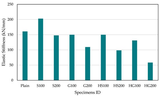
Figure 11.
Elastic stiffness of plain, steel, GFRP, and hybrid reinforced beams.
The hybrid beams with steel–GFRP longitudinal reinforcement and steel stirrups showed intermediate performance. HS100 achieved stiffness values comparable to those of steel-only beams (~150 kN/mm), confirming that adequate steel stirrups can maintain serviceability while benefiting from GFRP’s corrosion resistance. Conversely, HS200 dropped to ~100 kN/mm, further underscoring that insufficient stirrup confinement reduces stiffness regardless of the longitudinal reinforcement type. Service stiffness and crack distribution aligned with the transverse system, where steel stirrups produced tighter, more numerous cracks and higher stiffness compared to otherwise similar beams with GFRP stirrups. Hybrid beams with GFRP stirrups (HG100 and HG200) recorded the lowest stiffness values in the series (~130 kN/mm and ~60 kN/mm, respectively). Their poor performance demonstrates that GFRP stirrups, lacking yielding and adequate confinement capacity, are ineffective in maintaining serviceability, particularly at wider spacing. In summary, stiffness and serviceability were maximized in steel-reinforced beams with closely spaced stirrups (S100), while beams with GFRP stirrups exhibited the poorest performance. These results emphasize that the choice of stirrup material and spacing strongly governs service load behavior, with steel stirrups providing superior crack control and stiffness compared to GFRP stirrups.
The interplay between longitudinal reinforcement stiffness and transverse confinement explains the experimental trends identified in this study. The hybrid beams with steel stirrups demonstrated effective stress redistribution after the yielding of the steel, allowing the GFRP bars to remain active at elevated strain levels and support loads beyond the initial cracking point. This interaction clarifies the gradual post-yield softening and enhanced energy absorption characteristics observed in HS100. In contrast, beams including GFRP stirrups or had wider spacing showed signs of earlier diagonal cracking and a reduction in stiffness, which corresponds with the shear-dominated failures reported by Xiao et al. [39] and Oukaili et al. [31]. The findings indicate that hybrid reinforcement systems can effectively combine ductility and corrosion resistance, provided that sufficient steel confinement is maintained to ensure flexure-controlled behavior. The observed responses highlight the critical role of transverse reinforcement detailing in realizing the mechanical benefits of hybrid steel–GFRP reinforcement.
5. Conclusions
This study evaluated the flexural performance of RC beams that incorporated hybrid steel–GFRP longitudinal reinforcement under different stirrup materials (steel or GFRP) and stirrup spacings (100 mm or 200 mm). The experimental program consisted of nine beams tested under three-point bending, intentionally designed to isolate the effects of reinforcement composition and transverse confinement on various performance metrics, including strength, ductility, stiffness, cracking behavior, and failure mode.
The results demonstrate that the interaction between the type of longitudinal reinforcement and the method of transverse confinement governs the overall structural response. Beams with hybrid steel–GFRP bars and closely spaced steel stirrups (HS100) achieved the highest load capacity, deformation, and energy absorption. This finding confirms that the combination of steel ductility and GFRP tensile strength can be effectively utilized when sufficient steel confinement is present. Conversely, beams with GFRP stirrups or wider stirrups spacing (200 mm) demonstrated premature diagonal cracking and brittle shear failure. This highlights that inadequate transverse reinforcement suppresses the beneficial hybrid effect and accelerates shear-sensitive behavior.
In quantitative terms, HS100 reached an ultimate load of 162.5 kN and an ultimate midspan deflection of 19.7 mm, exceeding both steel-only and GFRP-only specimens. The ductility and toughness indices for HS100 improved by more than 40% compared to all-steel beams. Cracking measurements obtained after testing provide further clarification of the mechanisms: steel-reinforced beams (S100, S200) developed many closely spaced cracks (70–90 mm) but with the largest maximum widths ranging from 1.77 mm to 2.07 mm; conversely, GFRP-reinforced beams (G100, G200) formed fewer, more widely spaced cracks, particularly G200, which had 170 mm spacing and a maximum width of 1.80 mm. Hybrid beams display more uniform crack patterns, with the HG series (GFRP longitudinal bars paired steel stirrups) maintaining small maximum crack widths (0.50 mm) with 60–70 mm spacing and a total of 8 cracks, indicating effective restraint, improved stress redistribution, and higher service stiffness compared to GFRP-only configurations.
Overall, the findings suggest that hybrid reinforcement can effectively balance strength, ductility, stiffness, and durability when supported by adequate steel stirrups. From a practical standpoint, it is recommended that steel should be prioritized for tension zones (to provide necessary ductility) and for transverse reinforcement (to ensure confinement and crack control), while GFRP can be strategically used in areas prone to corrosion and in compression zones to enhance durability. This study offers experimental evidence to inform guide design optimization of hybrid RC members and supports the future development of design provisions and detailing recommendations for mixed-material reinforcement systems.
Future research should quantify long-term effects, including creep, shrinkage, and thermal/hygro-thermal cycling, on hybrid crack development and stiffness. Additionally, it should extend parametric studies (addressing section geometry, reinforcement ratios, bar layouts, and transverse reinforcement indices) to generalize the observed trends; investigate fatigue and cyclic loading to capture bond-slip and confinement interactions; and validate the conclusions on full-scale and continuous members exposed to realistic durability conditions is essential for consolidate practical recommendations for hybrid steel–GFRP flexural systems.
Author Contributions
Conceptualization, E.A. and A.A.; methodology, E.A.; software, A.A.; validation, E.A. and A.A.; formal analysis, A.A.; investigation, E.A. and A.A.; resources, E.A.; data curation, A.A.; writing—original draft preparation, A.A.; writing—review and editing, E.A.; visualization, A.A.; supervision, E.A.; project administration, E.A.; funding acquisition, E.A. All authors have read and agreed to the published version of the manuscript.
Funding
The authors gratefully acknowledge Qassim University, represented by the Deanship of Graduate Studies and Scientific Research, for the financial support of this research under grant number (QU-J-PG-2-2025-56846) during the academic year 1446 AH/2024 AD.
Data Availability Statement
The data presented in this study are available on request from the corresponding author.
Acknowledgments
The authors gratefully acknowledge Qassim University, represented by the Deanship of Graduate Studies and Scientific Research, for the financial support of this research under grant number (QU-J-PG-2-2025-56846) during the academic year 1446 AH/2024 AD. Also, during the preparation of this work, the authors used ChatGPT5 to refine language, improve readability, and enhance formatting consistency. After using this tool, the authors thoroughly reviewed and edited the content as needed and took full responsibility for the content of the publication.
Conflicts of Interest
The authors declare no conflicts of interest.
References
- Stewart, M.G.; Wang, X.; Nguyen, M.N. Climate change adaptation for corrosion control of concrete infrastructure. Struct. Saf. 2012, 35, 29–39. [Google Scholar] [CrossRef]
- Taffese, W.Z.; Nigussie, E. Autonomous corrosion assessment of reinforced concrete structures: Feasibility study. Sensors 2020, 20, 6825. [Google Scholar] [CrossRef] [PubMed]
- Zhang, Y.; Li, Q.; Zhang, F.; Xie, G. Estimates of econosmic loss of materials caused by acid deposition in China. Sustainability 2017, 9, 488. [Google Scholar] [CrossRef]
- Rafi, M.M.; Nadjai, A.; Ali, F.; Talamona, D. Aspects of behaviour of CFRP reinforced concrete beams in bending. Constr. Build. Mater. 2008, 22, 277–285. [Google Scholar] [CrossRef]
- Verre, S. Effect of Different Environments’ Conditioning on the Debonding Phenomenon in Fiber-Reinforced Cementitious Matrix-Concrete Joints. Materials 2021, 14, 7566. [Google Scholar] [CrossRef]
- Hosseinzadehfard, E.; Mobaraki, B. Corrosion performance and strain behavior of reinforced concrete: Effect of natural pozzolan as partial substitute for microsilica in concrete mixtures. Structures 2025, 79, 109397. [Google Scholar] [CrossRef]
- Davalos, J.F.; Chen, Y.; Ray, I. Long-term durability prediction models for GFRP bars in concrete environment. J. Compos. Mater. 2012, 46, 1899–1914. [Google Scholar] [CrossRef]
- Devaraj, R.; Olofinjana, A.; Gerber, C. Making a Case for Hybrid GFRP-Steel Reinforcement System in Concrete Beams: An Overview. Appl. Sci. 2023, 13, 1463. [Google Scholar] [CrossRef]
- Tran, H.; Nguyen-Thoi, T.; Dinh, H.-B. State-of-the-Art Review of Studies on the Flexural Behavior and Design of FRP-Reinforced Concrete Beams. Materials 2025, 18, 3295. [Google Scholar] [CrossRef]
- Elbawab, Y.; El Zoughby, Z.; ElKadi, O.; AbouZeid, M.; Sayed-Ahmed, E. Flexural Testing of Steel-, GFRP-, BFRP-, and Hybrid Reinforced Beams. Polymers 2025, 17, 2027. [Google Scholar] [CrossRef]
- Mustafa, S.A.A.; Hassan, H.A. Behavior of concrete beams reinforced with hybrid steel and FRP composites. HBRC J. 2018, 14, 300–308. [Google Scholar] [CrossRef]
- ACI Committee. Building Code Requirements for Structural Concrete Reinforced with Glass Fiber-Reinforced Polymer (GFRP) Bars: Code and Commentary; American Concrete Institute: Farmington Hills, MI, USA, 2022. [Google Scholar]
- Pang, L.; Qu, W.; Zhu, P.; Xu, J. Design Propositions for Hybrid FRP-Steel Reinforced Concrete Beams. J. Compos. Constr. 2016, 20, 04015086. [Google Scholar] [CrossRef]
- Latosh, F.; Al-Sakkaf, A.; Bagchi, A. Feasibility Study on the Effect of FRP Shear Reinforcements on the Behaviour of FRP-Reinforced Concrete Deep Beams. CivilEng 2023, 4, 522–537. [Google Scholar] [CrossRef]
- Megahed, K. Predicting flexural strength of hybrid FRP-steel reinforced beams using symbolic regression and ML techniques. Sci. Rep. 2025, 15, 20277. [Google Scholar] [CrossRef]
- Sümer, Y.; Öztemel, M. Investigation of the Effect of GFRP Reinforcement Bars on the Flexural Strength of Reinforced Concrete Beams Using the Finite Element Method. Fibers 2025, 13, 125. [Google Scholar] [CrossRef]
- Alsuhaibani, E.; Alturki, M.; Alogla, S.M.; Alawad, O.; Alkharisi, M.K.; Bayoumi, E.; Aldukail, A. Compressive and Bonding Performance of GFRP-Reinforced Concrete Columns. Buildings 2024, 14, 1071. [Google Scholar] [CrossRef]
- Aybar, K.; Yildirim, M.E.; Canbaz, M. Effect of High Temperature on the Mechanical Behavior of Glass Fiber–Reinforced Polymer Composite Bars under Compressive Loading. J. Mater. Civ. Eng. 2025, 37, 04025302. [Google Scholar] [CrossRef]
- Sarhan, M.M.; Al-Zwainy, F.M.S. Analytical investigations of concrete beams reinforced with FRP bars under static loads. Structures 2022, 44, 152–158. [Google Scholar] [CrossRef]
- Abbas, H.; Abadel, A.; Almusallam, T.; Al-Salloum, Y. Experimental and analytical study of flexural performance of concrete beams reinforced with hybrid of GFRP and steel rebars. Eng. Fail. Anal. 2022, 138, 106397. [Google Scholar] [CrossRef]
- Safan, M.A. Flexural Behavior and Design of Steel-GFRP Reinforced Concrete Beams. ACI Mater. J. 2013, 110, 677–685. [Google Scholar] [CrossRef]
- Gu, X.; Dai, Y.; Jiang, J. Flexural behavior investigation of steel-GFRP hybrid-reinforced concrete beams based on experimental and numerical methods. Eng. Struct. 2020, 206, 110117. [Google Scholar] [CrossRef]
- Yinghao, L.; Yong, Y. Arrangement of hybrid rebars on flexural behavior of HSC beams. Compos. Part B Eng. 2013, 45, 22–31. [Google Scholar] [CrossRef]
- Ruan, X.; Lu, C.; Xu, K.; Xuan, G.; Ni, M. Flexural behavior and serviceability of concrete beams hybrid-reinforced with GFRP bars and steel bars. Compos. Struct. 2020, 235, 111772. [Google Scholar] [CrossRef]
- Maranan, G.B.; Manalo, A.C.; Benmokrane, B.; Karunasena, W.; Mendis, P.; Nguyen, T.Q. Flexural behavior of geopolymer-concrete beams longitudinally reinforced with GFRP and steel hybrid reinforcements. Eng. Struct. 2019, 182, 141–152. [Google Scholar] [CrossRef]
- Araba, A.M.; Ashour, A.F. Flexural performance of hybrid GFRP-Steel reinforced concrete continuous beams. Compos. Part B Eng. 2018, 154, 321–336. [Google Scholar] [CrossRef]
- Dziomdziora, P.; Smarzewski, P. Reinforced Concrete Beams with FRP and Hybrid Steel–FRP Composite Bars: Load–Deflection Response, Failure Mechanisms, and Design Implications. Materials 2025, 18, 4381. [Google Scholar] [CrossRef]
- Kara, I.F.; Ashour, A.F.; Köroğlu, M.A. Flexural behavior of hybrid FRP/steel reinforced concrete beams. Compos. Struct. 2015, 129, 111–121. [Google Scholar] [CrossRef]
- ACI Committee. Guide for the Design and Construction of Structural Concrete Reinforced with Fiber-Reinforced Polymer FRP Bars; American Concrete Institute: Farmington Hills, MI, USA, 2015. [Google Scholar]
- Zhao, J.; Bao, X.; Yang, S.; Wang, Z.; He, H.; Xu, X. Experimental and Theoretical Studies on the Shear Performance of Concrete Beams Reinforced with Fiber-Reinforced Polymer Stirrups. Materials 2024, 17, 593. [Google Scholar] [CrossRef]
- Oukaili, N.; Allawi, A.A.; Issa, M.A.; Said, A.I.; AlBayati, A.; Ibrahim, T.H.; Wardeh, G. On the effectiveness of shear reinforcement type in GFRP-reinforced concrete beams: Experimental study. Struct. Concr. 2025, 26, 6547–6575. [Google Scholar] [CrossRef]
- ASTM A615/A615M-12; Specification for Deformed and Plain Carbon-Steel Bars for Concrete Reinforcement. ASTM: West Conshohocken, PA, USA, 2012. [CrossRef]
- D7957/D7957M-22; Standard Specification for Solid Round Glass Fiber Reinforced Polymer Bars for Concrete Reinforcement. ASTM: West Conshohocken, PA, USA, 2017. [CrossRef]
- Saudi Iron and Steel Company (Hadeed), Long Product Catalogue, SABIC, Al-Jubail Industrial City, Saudi Arabia. 2017. Available online: https://hadeed.com.sa/products (accessed on 27 October 2025).
- Leading the World in Durable Rebar, N.D. Available online: https://www.ikkmateenbar.com/resources/ (accessed on 27 October 2025).
- ASTM D7205/D7205M-21; Test Method for Tensile Properties of Fiber Reinforced Polymer Matrix Composite Bars. ASTM: West Conshohocken, PA, USA, 2021. [CrossRef]
- C 39/C 39M-9; ASTM C39 Standard Test Method for Compressive Strength of Cylindrical Concrete Specimens. ASM International: West Conshohocken, PA, USA, 2021. [CrossRef]
- ASTM C496; Standard Test Method for Splitting Tensile Strength of Cylindrical Concrete Specimens. ASM International: West Conshohocken, PA, USA, 2017. [CrossRef]
- Xiao, S.H.; Lin, J.X.; Li, L.J.; Guo, Y.C.; Zeng, J.J.; Xie, Z.H.; Wei, F.F.; Li, M. Experimental study on flexural behavior of concrete beam reinforced with GFRP and steel-fiber composite bars. J. Build. Eng. 2021, 43, 103087. [Google Scholar] [CrossRef]
Disclaimer/Publisher’s Note: The statements, opinions and data contained in all publications are solely those of the individual author(s) and contributor(s) and not of MDPI and/or the editor(s). MDPI and/or the editor(s) disclaim responsibility for any injury to people or property resulting from any ideas, methods, instructions or products referred to in the content. |
© 2025 by the authors. Licensee MDPI, Basel, Switzerland. This article is an open access article distributed under the terms and conditions of the Creative Commons Attribution (CC BY) license (https://creativecommons.org/licenses/by/4.0/).