Abstract
In order to surmount the characteristics of high steel consumption and cost in prefabricated buildings, as a novel structural component, reinforced concrete vierendeel sandwich plates (RC-VSP) could be effectively employed. However, RC-VSP is restricted by complex construction procedures and rigorous quality control demands. Reliable reinforcement connections are the keys to their prefabrication. This study employed the methods of 1:1 full-scale comparative tests and numerical analysis through finite- element modeling. It compared the mechanical behaviors of the continuous reinforcement control group and the upset sleeve assembly group under four-point cyclic bending conditions. It analyzed how sleeves’ distribution influences structural stress states and crack propagation processes. The results show a superior ductility and damage resistance, on the basis of the components’ attenuation amplitude of the secant stiffness remains around 50% after the loading test with a deflection of 1/100, and the equivalent damping ratio is greater than 13%. Furthermore, the high similarity of the strain responses demonstrated the connection achieves prefabricated structures’ “equivalent performance to cast-in-place ones”. Additionally, the sleeve joints have slightly better stiffness, minor stress concentration at sleeve ends. This study offers robust experimental and theoretical support for the integrated prefabricated application of RC-VSP and further facilitates the development of building structures toward higher efficiency and lower carbon emissions.
1. Introduction
Driven by the “dual carbon” goals, prefabricated buildings have been identified as a pivotal strategy to improve energy utilization efficiency, mitigate environmental burdens, and underpin the sustainable development of urban areas [1,2]. However, engineering practice shows that compared with the traditional cast-in-place structural system, certain prefabricated structures demonstrate an upward tendency in life-cycle costs, especially in terms of steel consumption, transportation, and hoisting. This issue further restricts their large-scale popularization and undermines the benefits of their engineering application [3]. Reinforced concrete vierendeel sandwich plates (RC-VSP) are also referred to as “Shear Key-Linked Bilateral Hollow Plates”. This structural component forms a two-way hollow grid structure by connecting the upper and lower ribs via shear keys, and functions in synergy with the upper concrete thin slab. The RC-VSP structure can significantly reduce structural self-weight and material usage. Meanwhile, its hollow regions enable the integrated layout of mechanical and electrical pipelines, which is beneficial for reducing floor height and enhancing space integration efficiency. Its feasibility has been verified in the applications of multi-story, high-rise, and long-span engineering projects [4], and the application examples of RC-VSP as shown in Figure 1.
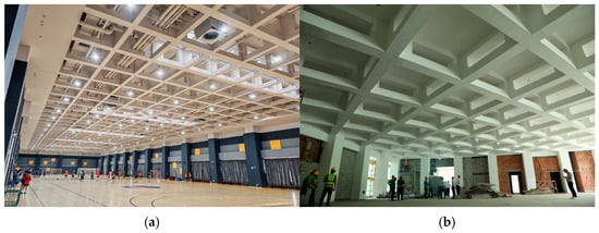
Figure 1.
Application examples of RC-VSP: (a) Zibo Sports School gymnasium; (b) Toyou Feiji Electronics high-rise factory building.
Nevertheless, vierendeel sandwich plates (VSP) adopting the traditional cast-in-place construction method are still confronted with challenges, including complex construction processes, high input costs for formwork and support systems, and high sensitivity to quality control. Promoting the prefabrication of this type of plate not only serves as an effective approach to breaking through these bottlenecks but also offers a new structural form that is more energy-efficient and economical for prefabricated building systems.
As a grid-type spatial structure, RC-VSP exhibits distinct prefabrication-oriented characteristics (shown in Figure 2). By arranging prefabricated joints at the inflection points between adjacent grids, the entire slab can be decomposed into multiple basic grid units with uniform dimensions [5]. The modular decomposition of the structure not only facilitates the generalization of prefabrication molds and improves the turnover rate of formwork but also enhances the collaborative efficiency of the “design-production-logistics-construction” industrial chain and the overall assembly efficiency of the structure.
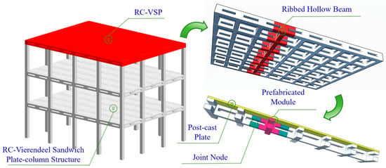
Figure 2.
The disassembled schematic diagram of RC-VSP.
Compared with conventional prefabricated frame systems, VSP features a larger quantity of assembly joints and more constrained assembly space. Consequently, the safety, assembly efficiency, and economy of the joints have thereby emerged as core factors governing the portability of the system. Among these factors, realizing reliable connections under the boundary conditions of “narrow cross-sections and high-density reinforcement” is of particular criticality. Traditional tied connections are prone to inducing reinforcement congestion. Welded connections exhibit high sensitivity to process control and heat-affected zone management, along with inadequate quality stability [6]. The force transfer of grouted sleeves depends on the strength and bonding effect of the grouting material, and the effect is greatly influenced by the grouting fullness. This connection method is mostly used in vertical structures where compactness is easy to control. Moreover, the diameter of the sleeves is often large, making it unsuitable for complex structures such as RC-VSP [7,8]. In contrast, the mechanical upset sleeve connection transfers force through mechanical bite force, which has high stability. It can avoid cross-section weakening through upsetting pretreatment and meet the requirement for sliding adjustment during assembly. In view of this, this paper focuses on the assembly technology of upset–threaded sleeves in adaptation to RC-VSP with small cross-sections and complex joints.
Existing studies have offered fragmented evidence regarding the assimilability of RC-VSP. Liu et al. (2016) verified the stress distribution characteristics and mechanical behaviors of RC-VSP structures via numerical simulation methods [9]. Chen et al. (2025) highlighted the assembly orientedassembly-oriented characteristics of RC-VSP and verified the feasibility of the assembly process for this type of structure through engineering case studies [4]. Regarding the connections of prefabricated components, Wan et al. (2020) conducted numerical simulations of eccentric loading tests on the joints of U-shaped steel-concrete composite beams [10], while Yu et al. (2023) carried out full-scale static loading tests on prefabricated steel-concrete sandwich panels [11]. These studies have confirmed the assimilability of VSP structures; however, they were limited to steel-concrete composite systems and did not involve RC systems. Chaliori et al. (2013) and Liu et al. (2024), respectively, explored the mechanical properties (encompassing stiffness, strength, deformation capacity, ductility, and energy dissipation performance) of RC beam members with sleeve connections via low-cycle repeated loading tests [12,13,14]. Nevertheless, these studies were confined to grouted sleeve connections and targeted traditional beam structures.
Therefore, despite the progress attained in the research on VSP structures and RC-related technologies for prefabricated building modules, these achievements have not directly tackled two core issues: first, whether prefabricated RC-VSP with upset sleeve connections can reach (or not be inferior to) the equivalent cast-in-place system in terms of key mechanical indicators, including load-bearing capacity, stiffness, and ductility. Second, what are the influence mechanisms of different sleeve distribution/arrangement patterns on the equivalent stiffness of assembly joints and crack propagation, and whether there exists an engineering-applicable arrangement optimization strategy. The aforementioned research gaps have constrained the replicable and standardized application of this system in engineering practices. To date, there have been no sufficient experimental proofs or research reports.
In light of the above context, this study takes the “assembly technology of RC-VSP based on upset sleeve connections” as the research focus and establishes a dual “experimental-numerical” verification framework: (1) A 1:1 full-scale comparative test was carried out, in which a full-length reinforcement control group and an upset sleeve assembly group were established. A low-frequency unidirectional cyclic loading regime was employed to systematically assess the load-bearing capacity, stiffness degradation, ductility, and failure mode of the specimens, so as to verify the performance equivalence of the prefabricated system relative to the cast-in-place system. (2) An experimentally calibrated finite element model was established to explore the effects of different sleeve distribution schemes on the equivalent stiffness, strain concentration, and crack development of joints; on this basis, actionable suggestions for connection arrangement were proposed. Through the cross-validation of experimental data and numerical results, this study aims to provide reliability validation and design method support for the integral assembly of RC-VSP, and offer a technical pathway balancing performance and economy for the goals of green construction and carbon reduction.
2. Experimental Design
2.1. Member Design
The flexural performance and load-bearing capacity of RC-VSP structures are generally assessed by investigating the mechanical properties of open-web sandwich beam members [15]. Considering the structural characteristics of RC-VSP, the design of ribbed beams is more consistent with the overall structural performance of the system. Therefore, the experimental members were designed as 6 m-long ribbed single-frame beams with a 1:1 conventional engineering scale (grid size: 1000 mm × 1000 mm). The rib width at the joint of each span was 300 mm (with two parallel ribs), and each span could be divided into four structural components: upper rib, lower rib, cover plate, and shear key. Specifically, the height of each upper rib was 100 mm, the height of each lower rib was 150 mm, and the thickness of the cover plate was 50 mm; the three-dimensional dimensions of the cross-shaped shear key were 350 mm × 200 mm × 100 mm. The specific dimensions and detailed drawings of the members are presented in Figure 3, and the reinforcement arrangement is illustrated in detail in Figure 4.
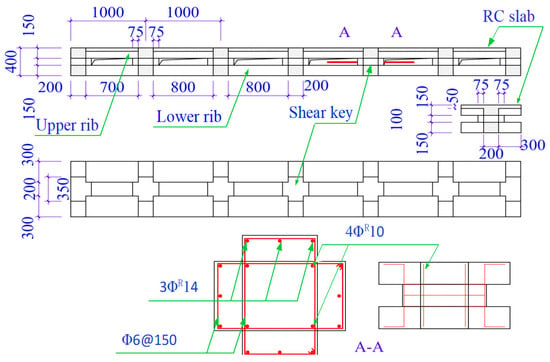
Figure 3.
Dimensions diagram of experimental components (unit: mm).
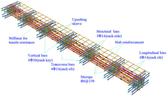
Figure 4.
Reinforcement drawing of experimental components.
The primary type of steel bar adopted in the test was HRB400: the transverse and longitudinal main bars were ΦR14 threaded steel bars, while the vertical bars of the shear keys were ΦR10 threaded steel bars [16,17,18]. In accordance with the requirements of the comparative experiment, two groups of specimens were established, respectively: a control group with continuous steel bars and an assembly group with upset sleeves. The sleeve connection joints of the assembly group were positioned at the mid-span, and this configuration could facilitate the standardization of prefabricated modules. The mechanical properties of the two groups of structures were compared and validated via the four-point bending test [19,20], so as to verify the reliability of the prefabricated application of the RC-VSP structure.
2.2. Experimental Preparation
First, C30 concrete specimens and Φ14 HRB400 steel bars were prepared with the same raw materials as those used for the test components. The reliability of the materials employed in the experiment was verified via axial compression tests on the concrete specimens and pull-out tests on the steel bars [21,22]. In the axial compression test, the average axial compressive strength of the concrete specimens was 32.7 MPa, which complies with the design criteria and specification requirements.
For the upset steel bars, steel sleeves with an inner diameter of Φ16 and an outer diameter of Φ24 were adopted for connection. The pull-out test results of the sleeve-connected steel bars (shown as Figure 5) satisfy the requirements for Class I steel sleeve joints, and the detailed test conclusions are presented in Table 1.
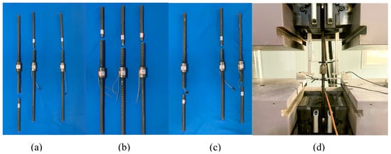
Figure 5.
The pull-out test of upset sleeve-connected steel bars: (a) large-deformation; (b) unidirectional; (c) unidirectional; (d) test arrangement.

Table 1.
Conclusion of the tensile pull-out test of steel bars connected by upsetting sleeves.
Second, the ABAQUS finite element simulation method was adopted to simulate the displacement response and load-bearing performance of the test members [23,24]. As illustrated in Figure 6, based on the displacement-load (D-L) curve obtained from the four-point bending loading simulation, the elastic modulus of the member underwent significant variations at the displacement points of 2.5 mm and 21.2 mm. When the displacement reached 21.2 mm, the structure entered the yield stage and transitioned to the plastic deformation phase; upon the displacement exceeding 33.3 mm, the structure exhibited a distinct “nonlinear gentle growth” characteristic.
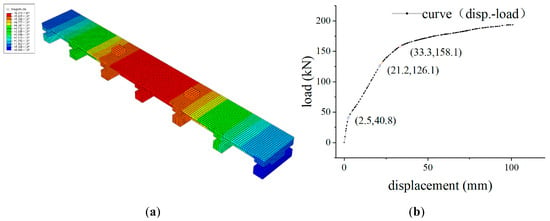
Figure 6.
The D-L response of 4-point continuous loading on simulation components: (a) heat map; (b) the D-L curve.
Based on empirical data, the yield load of ordinary reinforced concrete beams generally accounts for 70% to 90% of the ultimate load. Considering the superior energy dissipation capacity and ductile safety reserve of hollow sandwich ribbed beams, with 70% taken as the ratio of the yield load (126.1 kN) to the ultimate load, the expected ultimate load was extrapolated to be 180 kN. In line with relevant codes, the deflection control limit in the design of conventional reinforced concrete beams is 1/400 [25,26], while for vierendeel sandwich ribbed beams (hereinafter referred to as VSRB), this limit can usually be approximated as 1/200. In this experiment, the maximum displacement was controlled at 1/100 of the span length; specifically, for the 6 m-long member, the mid-span ultimate displacement was set to 60 mm. This control strategy was designed to fully exploit the mechanical properties of the member.
2.3. Loading Protocol
To verify the structural performance reliability of Vierendeel Sandwich Ribbed Beams (VSRB) under two configurations (continuous reinforcement and upset sleeve connection), the four-point bending loading method was adopted as the core experimental approach in this study. This method was used to analyze the load-bearing capacity indices (including strain response, crack propagation, and yielding behavior) of the members in different span segments (i.e., pure bending segment and shear-bending segment), while simultaneously validating the energy dissipation performance and engineering application feasibility of the members.
The loading was carried out using a hydraulic jack fixed to a reaction frame. The vertical load was uniformly transferred via a distribution beam, and the reaction points were supported by hinged supports. This setup accurately simulated the simply supported boundary conditions [27], thereby avoiding the generation of additional bending moments. Meanwhile, “rigid backing plates” were placed at the contact interfaces between both ends of the distribution beam and the reaction point supports to prevent local concrete crushing induced by uneven distribution or excessive magnitude of local compressive stress. The detailed loading schematic is illustrated in Figure 7.
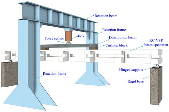
Figure 7.
Schematic diagram of 4-point bending loading of experimental components.
Based on the finite element-simulated monotonic loading test of VSRB in the experimental preparation stage and the expected ultimate deflection, the ultimate displacement was assumed to be 60 mm. Using the four-point bending method, cyclic loading tests were conducted on the continuous reinforcement member (hereinafter referred to as TC) and the upset sleeve connection member (hereinafter referred to as US), respectively, adopting a displacement-controlled stepwise loading mode.
The loading process was divided into two stages. In the first stage, the displacement was increased in incremental steps of 2.5 mm per step. After loading the preset displacement in each step, the load data were recorded. The control mode was switched to force control for unloading to 0 kN, followed by cyclic loading. Each displacement level in this stage was subjected to three loading cycles until the displacement reached 25 mm. In the second stage, the displacement was increased in incremental steps of 5 mm per step, and each displacement level was subjected to two loading cycles until the displacement reached 60 mm. If the member remained structurally intact when the displacement exceeded 60 mm, an attempt was made to continue loading until the displacement reached 65 mm, after which the maximum load was recorded. Throughout the experiment, data on structural load, displacement, strain responses of concrete and steel bars, and crack propagation behavior were collected separately [28].
2.4. Data Monitoring
Firstly, a static stress–strain testing system was employed to collect and record the strain data of the test members during the experiment. Two Tester 3826 devices and one Donghua 3816 device were used as measuring instruments for the acquisition of strain data of concrete and steel bars under cyclic loading [29]. Secondly, displacement sensors were utilized to measure the deflection variation in the beam at each loading stage, while spoke-type pressure sensors were employed to record the load during the loading process. Thirdly, the crack development process of each span was recorded via manual observation. Meanwhile, two-dimensional digital image correlation (DIC) technology was applied to observe and characterize the crack propagation behavior in the pure bending section of the beam [30].
3. Implementation Process
C30 concrete and HRB400 steel bars served as the main raw materials for the experiment. The reinforcement arrangement was consistent with the design conditions and parameters of the integral VSP structure. Concrete pouring, vibration, and curing processes were conducted in strict compliance with relevant specifications to ensure that the experimental members matched the structural state of actual engineering projects, and the details are shown in Figure 8.
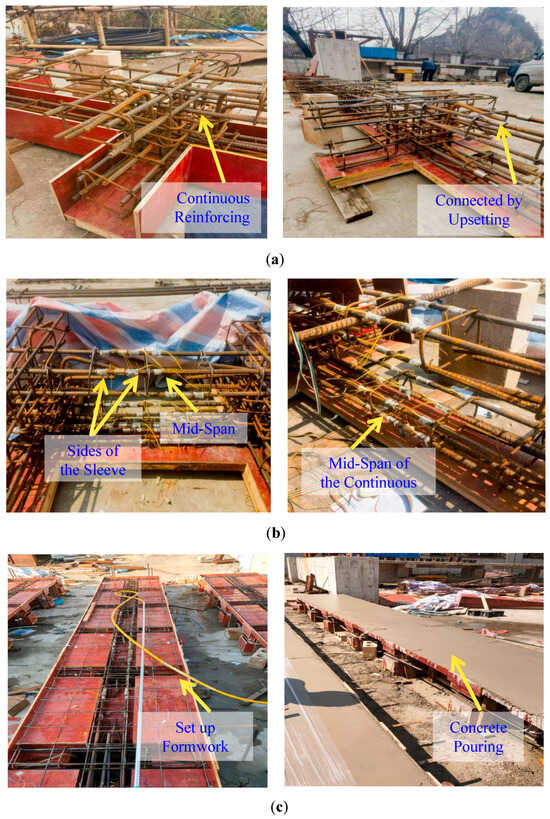
Figure 8.
The implementation processes of different test components: (a) rebars tying; (b) paste strain gauges; (c) structural formation.
Preparation for structural strain sensing and data collection was performed in the following steps. Firstly, steel bars were positioned, and strain sensors were then bonded to the steel bars. Subsequently, the wire connection terminals of the sensors were reserved, and the specific positions of the sensors were numbered. After the concrete curing period expired and the structure was placed on the test bench, additional strain sensors were bonded. Finally, key observation positions, including the upper and lower ribs of each span of the concrete and the open-web corners, were numbered and marked. The details were shown in Figure 9.
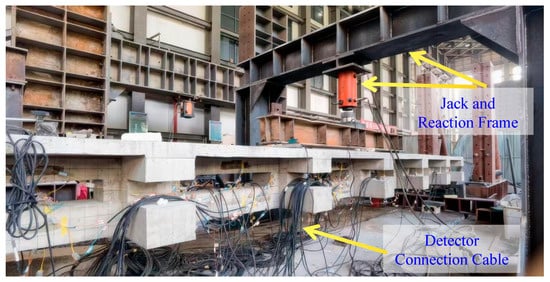
Figure 9.
Installation in the test.
A four-point bending cyclic loading test was performed by means of a steel reaction frame. The loading device applied loads through a jack, and the load was evenly transferred to the two end loading points via a distribution beam. The loading protocol adopted a two-stage equal-displacement stepwise incremental loading approach. During the loading process, load, displacement, and strain data were continuously recorded, while the crack development and failure mode of the specimen were observed in real time (shown in Figure 10).
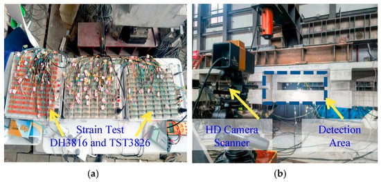
Figure 10.
Process monitoring: (a) strain test; (b) DIC system.
4. Experimental Results and Analysis
4.1. Load–Displacement Characteristics
Under the graded cyclic loading condition, the load–displacement data recorded in the experiment are presented in Figure 11. Several key findings can be summarized as follows:
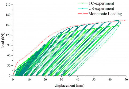
Figure 11.
The comparison of D-L curves between the US and TC.
(1) The cyclic loading envelope curves of the test specimens with continuous reinforcement (TC, monolithic casting) and upset sleeve connection (US) exhibit a high degree of similarity. Furthermore, the outermost displacement-load (D-L) boundaries of both types of specimens show good consistency with the nonlinear curves derived from simulated monotonic loading, and their amplitude ranges are consistent with theoretical predictions. This result confirms that the US specimens are essentially equivalent to the monolithic cast specimens in terms of load-bearing capacity and flexural strain behaviors [31,32,33].
(2) Both types of specimens conform to the three-stage development law of reinforced concrete beams, i.e., elastic stage → plastic stage → yield stage, thus exhibiting good structural stability. As shown in Table 2, based on the reciprocating loads and effective displacements recorded in 18 loading levels, the change rhythms of the secant stiffness of the two test components are consistent. The overall stiffness attenuation amplitudes are 55.6% and 49.7%, respectively, and the stiffness deviation rate in each loading level is within 18%. Specifically, in the elastic and elastoplastic stages, the secant stiffness of the US specimen is slightly higher, with the deviation rate ranging from 8% to 18%. In the yield stage, under the same displacement conditions, the secant stiffness deviation rate of the US specimen is reduced to about 5%. Compared with the TC specimen, the US specimen has a slightly larger stiffness, and the stiffness attenuation amplitude is around 50%. This indicates that both components possess superior ductility and damage resistance while ensuring stable bearing capacity.

Table 2.
Secant stiffness attenuation of test components.
(3) The D-L curves obtained from cyclic loading form a full and plump envelope area. According to the principles of structural dynamics, the envelope area of cyclic loading curves directly characterizes the energy dissipation capacity of a structural member. According to the envelope diagrams formed by the test components, the area of the envelope diagram, peak load, and displacement were measured. The equivalent damping ratio was calculated as follows:
The calculation results are shown in Table 3. The equivalent damping ratios of the two test components both exceed 13%, which is much higher than the design value of 5% required by the seismic code. The large area of the hysteresis curve and the high equivalent damping ratio indicate that the RC-VSP specimens have strong energy-dissipation performance [34,35].

Table 3.
Equivalent damping ratio of the load—displacement hysteresis curve of the experiment component.
(4) Even when the displacement increases to more than 60 mm (corresponding to an ultimate deflection exceeding 1/100 of the span length, which is far exceeding the deflection limit of conventional reinforced concrete members), no load drop occurs, and the overall structure remains free from fracture or damage. This observation fully proves that the structure has outstanding ductility and sufficient safety performance, endowing it with the capability to resist catastrophic failure under extreme loading scenarios [36,37,38].
4.2. Crack Propagation Behavior
The entire process of crack initiation and propagation can be divided into three distinct stages, whose detailed characteristics are as follows:
Stage 1: This stage ranges from the start of loading to the onset of micro-cracks (crack width < 0.05 mm). Micro-cracks began to emerge sequentially when the displacement reached 5 mm, which corresponds to a load of approximately 32 kN. During this stage, the formation of cracks was minimal and exhibited a localized distribution.
Stage 2: In this stage, micro-cracks propagated, and their widths expanded to the range of 0.05 mm–0.3 mm. This process occurred as the displacement increased from 5 mm to 20 mm, experiencing 6 loading levels and 18 cyclic loading cycles, with the corresponding load reaching approximately 92 kN. Notably, diagonal cracks appeared in the 2nd span (i.e., the shear-bending segment), and the propagation rate of these diagonal cracks was slightly higher than that of the vertical cracks in the pure bending segment.
Stage 3: Cracks continued to expand synchronously with the increase in displacement and load. In the pure bending segment, through-cracks were gradually formed [39]. Specifically, when the displacement reached 30 mm, the maximum crack width increased to 0.45 mm, corresponding to a load of approximately 120 kN. When the displacement reached 35 mm, the propagation rate of diagonal cracks in the shear-bending segment became significantly higher than that of cracks in the pure bending segment, and the diagonal cracks extended toward the flange ribs along the shear keys. Subsequently, all existing cracks widened gradually, with the maximum crack width reaching 1.4 mm (corresponding to a load of approximately 144 kN). After the displacement exceeded 60 mm, the crack width basically ceased to increase, indicating that the crack development entered a stable stage.
Figure 12 illustrates the crack propagation patterns in the pure bending segment (3rd span) and shear-bending segment (2nd span) of the specimen after cyclic loading. Figure 13 and Figure 14, captured by a high-resolution camera, show the crack conditions of the TC and US specimens, respectively, when the mid-span displacement reaches 10 mm and 30 mm.
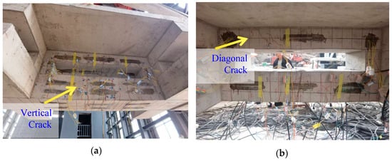
Figure 12.
The corresponding crack propagation of different span sections: (a) pure bending section; (b) shear-bending section.

Figure 13.
The pure bending crack propagation of TC members: (a) situation of (Disp.) 10 mm; (b) situation of (Disp.) 30 mm.

Figure 14.
The pure bending crack propagation of US members: (a) situation of (Disp.) 10 mm; (b) situation of (Disp.) 30 mm.
4.3. Strain Response of Concrete Under Loading
The test member featured a 6-span symmetric configuration, and its overall strain response complied with the law of symmetric variation. Therefore, the strain response was analyzed based on the strain data collected from the first 3 spans. In accordance with the stepwise incremental cyclic loading protocol, the strain data exhibited cyclic characteristics that were synchronized with load variations: the strain values decreased during the unloading phase and increased correspondingly during the reloading phase. Moreover, the variation in strain sensor data exhibited a significant correlation with the loading level, presenting an overall distinct “stepped” variation trend [40,41,42]. The strain variation of different spans with the loading level is shown in Figure 15 (Note: “US-C-3D1” denotes the concrete strain measured by Strain Sensor No. 1 at the lower rib of the 3rd span in the upset sleeve-connected member). The specific characteristics are analyzed as follows:
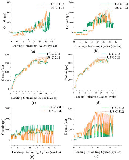
Figure 15.
The comparison of concrete strain between the US and TC: (a) Position 3 of the upper rib of 1st span; (b) Position 1 of the lower rib of 2nd span; (c) Position 1 of the lower rib of 3rd span; (d) Position 2 of the lower rib of 4th span; (e) Position 1 of the lower rib of 5th span; (f) Position 2 of the lower rib of 6th span.
(1) First span (end region): This region is mainly subjected to shear force, with minimal effect of bending moment. The strain values measured by strain sensors at the upper and lower ribs are relatively small, all within 800 microstrain (με), and no obvious fluctuations are observed. This indicates that the 1st span is not the main force-bearing region of the structure, and its overall strain response is gentle and stable.
(2) Second span (region under combined shear and bending): Located between the end segment and the pure bending segment, this span is subjected to the combined action of shear force and bending moment, rendering it the most complex force–bearing region of the member. Test results show that the strain values in this region increase remarkably, with the strain range reaching up to 8000 με. Additionally, the initial strain values exhibit an obvious stepwise increasing trend with the loading level, and the maximum strain fluctuation amplitude under a single loading step reaches 1200 με. Combined with the observation of diagonal cracks in this span, it can be concluded that under the combined action of shear and bending, relatively large absolute displacements or strains occur in some areas of the lower rib of this span, and the accumulation of residual strains is notable. This phenomenon is consistent with the theoretical law of strain response under the combined action of shear and bending [43].
(3) Third span (pure bending region): As the middle span, this region is not affected by shear force and only bears bending moment, thus serving as a key region for studying the flexural performance of beam-like members [44,45]. Compared with other spans, the 3rd span exhibits the largest strain variation amplitude under each loading step and is the most sensitive to load variations. Specifically, in more than 50% of the loading steps, the strain fluctuation range under a single step is approximately 2000 με. It should be noted that the overall strain range of this span is within 3000 με, which is smaller than the maximum strain value of the 2nd span. This indicates that although the middle span bears a large bending moment, no diagonal cracks or transverse cracks are formed, thus avoiding obvious residual strain accumulation.
(4) Performance comparison of structures with different connection methods: Each subfigure in Figure 15 includes the strain data of both the US member and the TC member. Comparative analysis reveals that the two types of structures exhibit highly similar strain response characteristics, and there are no significant differences in strain amplitude or evolution regularity at the same observation position. This result confirms that the US method can effectively guarantee the basic mechanical performance of the TC structure.
(5) Analysis of Abnormal Phenomena in Strain Monitoring: In addition to the aforementioned regular strain responses, approximately 24% of the strain sensors displayed abrupt anomalies in their monitoring data—their readings suddenly increased by dozens of times, followed by a cessation of subsequent strain response, and this variation was far beyond the normal strain fluctuation range. Based on the observation of crack development in the members and the structural characteristics of the test specimens, the primary cause of this abnormal phenomenon is inferred as follows: during the loading process, concrete cracks initiated and propagated continuously, causing the strain sensors bonded to the concrete surface to fracture along with the crack extension. This gave rise to a sudden and notable anomaly in the strain monitoring data, consequently.
4.4. Strain Response of Reinforcement Bars Under Loading
The strain testing of reinforcement bars adopted the same loading synchronization, equipment transmission sharing, and simultaneous data collection protocols as the concrete strain testing. The reading variation in the strain sensors exhibited a positive correlation with the loading level [46,47]. The “stepped” variation trend displayed was consistent with the response behavior of concrete, yet certain differences existed. The specific strain conditions are illustrated in Figure 16:
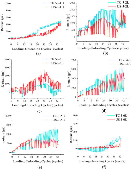
Figure 16.
The comparison of steel bar strain between the US and TC: (a) The upper rib of 1st span; (b) The lower rib of 2nd span; (c) The lower rib of 3rd span; (d) The lower rib of 4th span; (e) The upper rib of 5th span; (f) The upper rib of 6th span.
(1) For the 1st and 6th spans, the strain peaks were extremely low (within 500 με), and the fluctuation amplitudes were less than 100 με. This indicates that the end regions serve as secondary force–bearing components of the structure, where the mechanical response under cyclic loading is minimal, and the strain of the reinforcement bars remains stable, with no significant damage accumulation.
(2) For the 2nd and 5th spans, the strain peaks were relatively large, with the maximum value reaching nearly 2500 με, and the strain fluctuation was significant (amplitude: 500–1800 με). This demonstrates that for the shear-bending segments (as core force–bearing regions), the plastic development of the reinforcement bars was adequate, and the damage evolution process was complex.
(3) For the 3rd and 4th spans, the strain peaks were the highest (exceeding 3000 με), and the strain fluctuation amplitudes presented a broader range (300–2600 με) with higher regularity. This reflects the mechanical property of pure bending segments dominated by bending moment, where damage accumulation proceeds in a gradual fashion.
(4) Overall, the strain responses of the US and TC specimens were consistent with minimal variations. Certain individual spans of the specimens (e.g., the 5th and 6th spans) demonstrated more stable fluctuation characteristics. This indicates that, on the premise that experimental results validate the application feasibility of prefabricated structures, members with partial sleeve connections exhibit more stable strain responses.
(5) Compared with the concrete strain data, the proportion of abnormal abrupt changes observed in the steel bar strain is significantly lower (reduced by approximately 8.5%). This suggests that the failure ratio of steel bars during the cyclic loading process is relatively low, and the overall tensile performance of the members tends to be stable.
Based on the above test results, the RC-VSP structures demonstrate comprehensive and excellent seismic performance. Firstly, both the US and TC specimens exhibit good stiffness stability. The staged development of cracks is highly coordinated with the elastic-plastic-yield stages. Even in the yield stage, the specimens can still maintain a strong bearing capacity contribution. Secondly, under cyclic loading, a full hysteresis curve is formed, and the equivalent damping ratio exceeds 13%, endowing the structure with high-efficiency seismic energy dissipation capacity. Thirdly, under extreme displacement conditions with an ultimate deflection exceeding 1/100, there is no fracture, damage, or load-drop phenomenon. This fully demonstrates its excellent ductility, collapse-resistance ability, crack-control performance, and resistance to brittle failure. Thus, this structure is fully applicable to seismic-fortified projects.
5. Finite Element Simulation
5.1. Establishment of Finite Element Model
All structural components were modeled as three-dimensional (3D) deformable entities. Specifically, the concrete components and reinforcement bar (rebar) sleeves were discretized into meshes using the C3D8R element. The rebar components were modeled using the T3D2 truss element. The concrete is an elastic material of C30 type, the steel bars are elastoplastic materials of HRB400 type, and the sleeve is an elastoplastic alloy steel material of Q355 type [48]. Considering the reliable interfacial bonding performance between the sleeves and rebars, and all failure modes observed in the pull–out tests of sleeve connections were characterized by rebar fracture, the “Embedded region” constraint was employed to characterize the contact relationship between the rebars and sleeves. The two ends of the four-point loading are hinged supports. All loads are coupled constraints, moving synchronously and evenly distributed [49]. The rest of the geometric parameters and material constitutive parameters are set equivalent with reference to the experimental components. Through meshing, the test component generates 41,973 elements and 61,185 nodes.
Based on the two configurations of the experimental specimens, an additional US (upset sleeve connection) configuration was introduced in the finite element modeling, resulting in a total of three structural models. These models are designated as follows: the cast-in-place structure with continuous reinforcements (denoted as Model-TC), the upset sleeve connection structure with offset arrangement (denoted as Model-US-o), and the upset sleeve connection structure with aligned arrangement (denoted as Model-US-a). Subsequently, the displacement-load (D-L) curves of Model-TC and Model-US-o were simulated in accordance with the experimental loading protocol. A comparison between the simulated curves and the experimentally measured data is shown in Figure 17. The response displacement-load (D-L) curves of the finite element models are highly consistent with the experimental data, which confirms that the established finite element models are valid and can accurately reproduce the macroscopic mechanical responses of the specimens [50].
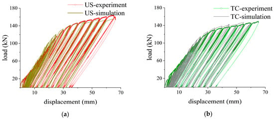
Figure 17.
The comparison of D-L curves between simulation and experiment: (a) component with upset sleeve (US) connection; (b) component with the continuous (TC) reinforcement.
5.2. Comparative Analysis of Models
On the premise of verifying the reliability of the established finite element models, D-L curves (as illustrated in Figure 18) and contour diagrams were generated by simulating the loading process of the three structural models. These results were employed to verify the crack propagation behavior of concrete under tensile failure, and to conduct a comparative analysis of the actual effects of different distribution positions of upset sleeves on stress distribution and crack propagation. This further provides insights into the detailed design of connection joints for prefabricated modular configurations in RC-VSP [51].
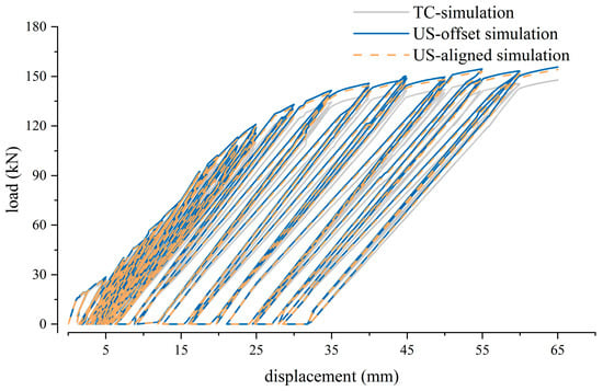
Figure 18.
The comparison of simulated D-L curves of three structural forms.
As shown in Figure 18, the D-L curves of components with sleeve connections (US structures) are nearly identical to those of components without sleeve connections (TC structures), and variations in sleeve positions do not significantly affect the structural load-bearing capacity. Subsequent loading simulations were performed on the three models, generating contour plots of concrete compression damage (Damage C) and tensile damage (Damage T), with the key findings analyzed as follows:
(1) Comparison between TC and US structures
First, after the completion of displacement loading, as shown in Damage T in Figure 19, the slab damage exhibited only slight differences in the 2nd and 5th spans (shear-bending segments), with the local damage of US structures being slightly less severe. Second, under the condition of maximum displacement corresponding to compression damage, as shown in Damage C in Figure 19, the local damage degree of US structures remained slightly lower—this indicates that the presence of upset sleeves slightly enhances the shear stiffness of the members. Third, the sleeves influence the propagation of concrete tensile cracks, particularly in the initial stage, as shown in Figure 20: crack propagation at the sleeve sections is relatively delayed, whereas cracking at both ends of the sleeves occurs earlier. This suggests that the tensile stiffness in the sleeve connection regions is slightly increased, resulting in smaller strains under equivalent tensile stress; however, stress concentration at the sleeve ends leads to premature cracking. Fourth, when the maximum displacement of the VSRB exceeds 30 mm (i.e., Amm (i.e., a deflection of 1/200), the tensile damage behaviors of the three models become essentially consistent, indicating that the overall flexural performances of the different models are comparable after entering the plastic stage [52,53].
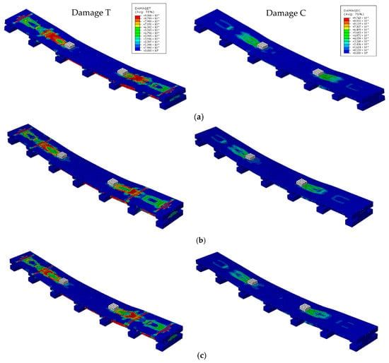
Figure 19.
The comparison of concrete tensile damage and compressive damage in the final stage: (a) model-TC; (b) model-US-offset; (c) model-US-aligned.
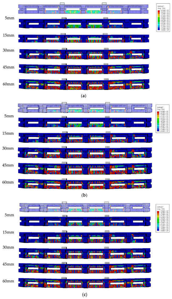
Figure 20.
The comparison of concrete tensile damage from 5 mm to 60 mm stage: (a) model-TC; (b) model-US-offset; (c) model-US-aligned.
(2) Comparison between different sleeve arrangement scenarios
As shown in the comparison between Figure 20b and Figure 20c. In the initial crack stage, differences in tensile strain are concentrated in the lower rib region of pure bending segments. The displacement range of the crack is 5 mm–10 mm. For Model-US-a (upset sleeve connection with aligned arrangement), the strain is minimized in sleeve-located sections and maximized in sleeve-end sections. In contrast, Model-US-o (upset sleeve connection with offset arrangement) exhibits relatively uniform strain in the mid-span, with the most strain-sensitive area located at the sleeve ends in the bottom layer of the lower rib.
In the crack development stage (displacement range: 10 mm–15 mm), the through—cracks in Model-US-a are formed earlier than those in Model-US-o, specifically at sections with stress concentration near the sleeve ends. Both types of members develop a similar number of cracks; however, the crack positions vary slightly depending on differences in sleeve layout, and cracks or damage consistently initiate first at the sleeve ends.
In the crack propagation stage (displacement range: >20 mm), cracks and damage in Model-US-a are relatively concentrated: the strain in the middle of the sleeve sections is minimal, and crack propagation proceeds stepwise from the middle toward both ends. In contrast, cracks and damage in Model-US-o exhibit a relatively uniform distribution. As displacement and load increase, both types of members only exhibit propagation of existing cracks, with few new cracks generated, and their overall crack densities are similar.
5.3. Simulation Conclusions and Action Mechanism
Finite element simulation results demonstrate that the upset sleeve connection enables reliable force transmission with reinforcing bars through the “Embedded Region” contact configuration. The stiffness of the sleeves contributes to enhancing the shear resistance and tensile performance of the joint region. Local stress concentration is only observed at the sleeve ends, resulting in earlier crack initiation; however, this effect is confined to the local region of the joint and exerts no adverse impact on the overall mechanical properties of the member. These findings thus verify the safety and feasibility of applying upset sleeve connections in VSP.
Furthermore, the arrangement of Model-US-o (upset sleeve connection with offset arrangement) can mitigate stress concentration at the sleeve ends and lead to a more uniform crack distribution, exhibiting superiority over the arrangement of Model-US-a (upset sleeve connection with aligned arrangement).
6. Conclusions and Inspiration
6.1. Key Conclusions
To resolve the connection bottleneck in the integral prefabrication process of reinforced concrete vierendeel sandwich plate structures (RC-VSP), this study designed and fabricated two full-scale (1:1) single-bay vierendeel sandwich ribbed beams (VSRB) with a span of 6 m and distinct configurations. Four-point cyclic bending tests were conducted to investigate the mechanical behaviors of the two specimens. Subsequently, the collected experimental data were used to verify the accuracy of the finite element models and the validity of the simulation tests. Furthermore, this model was employed to confirm the feasibility and reliability of applying upset sleeve connections in this type of structure, and the influence of sleeve layout configurations was analyzed. This research thereby provides guidance for the parameter design of key joints in the subsequent development of modular components. The specific conclusions are as follows:
(1) Under the four-point bending cyclic loading test conditions, the mechanical responses of the cast-in-place specimen with continuous reinforcement (TC) and the prefabricated specimen with upset sleeve connections (US) are highly consistent. The load–displacement envelope curves converge, and the calculated equivalent damping ratios of both exceed 13% (>5%). Both of the specimens demonstrate excellent bearing capacity, ductility, and damage resistance. Furthermore, the variation laws of the secant stiffness of the two components are consistent, with the stiffness attenuation amplitude being approximately 50%. The stiffness of the US component is slightly larger, and the proportion of stiffness increase in different loading stages ranges from 5% to 18%. Through the comparison of various mechanical performance indicators, the RC–VSP structure with upset—sleeve connection can achieve the expectation of its prefabricated performance being “equivalent to cast-in-place”.
(2) Under extreme displacement conditions exceeding 1/100 of deflection, neither of the TC and US specimens exhibits signs of fracture, damage, or load reduction. Moreover, the cracks develop in a staged and regular manner and eventually tend to stabilize. The characteristics, such as bearing stability, energy-dissipation capacity, ductility reserve, and resistance to brittle failure, demonstrated by these two components, make the RC-VSP structures fully applicable to seismic-fortified projects.
(3) Finite element analysis of concrete crack propagation in specimens with different sleeve arrangements indicated that the inherent stiffness of the sleeves helps enhance the shear resistance and tensile performance of joint regions. Although local stress concentration was detected at the sleeve ends—resulting in premature cracking—this phenomenon was limited to the local joint area and did not exert an adverse effect on the overall mechanical performance of the specimens. Additionally, compared with the aligned sleeve arrangement (Model-US-a), the offset sleeve arrangement (Model-US-o) was more effective in alleviating end stress concentration, providing a reliable reference for the engineering design of prefabricated RC-VSP joints.
6.2. Inspiration for Future Research
Conduct structural performance tests on the complete prefabricated vierendeel sandwich plate-column structure. Based on the characteristics such as bearing stability, high-ductility reserve, and fatigue resistance demonstrated by the ribbed beam components in the cyclic loading test, the test structure could be further expanded to a more complete prefabricated vierendeel sandwich plate-column structure. The feasibility of applying the integral prefabricated reinforced concrete vierendeel sandwich plate-column structure in high-rise buildings is verified through large–scale seismic tests and ultimate load tests. Moreover, the test data provides support for the local design code of this new prefabricated structure, thus promoting the engineering application of this new structure and technology.
In addition, the assembly precision control technology for the integral prefabricated vierendeel sandwich plate-column structure could be investigated more. The standardized modular design of the prefabricated reinforced concrete vierendeel sandwich beams, plates, and columns can be carried out through BIM modeling and construction technique deduction. Furthermore, it can clarify the detailed parameters of steel bars’ layout in joints, to ensure the efficiency and reliability of module splicing joints.
Author Contributions
S.Q.: Writing—review and editing, Software, Investigation, Experimental research, Funding acquisition, Formal analysis. Y.W.: Investigation, Methodology. K.M.: Methodology, Conceptualization, Funding acquisition. J.C.: Review and editing, Experimental research, Funding acquisition, Conceptualization. All authors have read and agreed to the published version of the manuscript.
Funding
This research is supported by Guizhou Science and Technology Achievement Transformation Foundation [Grant No QKH2023081]; Guizhou University Survey and Design Foundation [Grant No. 202206]; Foundation of Guizhou University GZUF202034.
Data Availability Statement
The original contributions presented in the study are included in the article; further inquiries can be directed to the corresponding author.
Conflicts of Interest
The authors declare that they have no known competing financial interests or personal relationships.
Abbreviations
The following abbreviations are used in this manuscript:
| VSP | vierendeel sandwich plates |
| RC-VSP | reinforced concrete vierendeel sandwich plates |
| VSRB | vierendeel sandwich ribbed beams |
| US | upset sleeve connection |
| TC | the continuous (reinforcement) |
| D-L | displacement-load (curve) |
References
- United Nations Environment Programme Global Status Report for Buildings Construction, E.B./.O.L. 2024. Available online: https://www.unep.org/resources/report/global-status-report-buildings-and-construction (accessed on 12 April 2025).
- Ministry of Housing and Urban-Rural Development. 14th Five-Year Plan for the Development of the Construction Industry. 2022. Available online: https://www.gov.cn/zhengce/zhengceku/2022-01/27/5670687/files/12d50c613b344165afb21bc596a190fc.pdf (accessed on 13 April 2025).
- Jin, Q.; Xu, C.; Liu, X. Research on Factors Affecting the Life-Circle Cost of Prefabricated Building in China. In Proceedings of the International Conference on Construction and Real Estate Management, Charleston, SC, USA, 9–10 August 2018; pp. 106–113. [Google Scholar] [CrossRef]
- Chen, H.; Yang, Y.; Yian, P.; Zhou, Z.; Chen, J.; Wei, Y.; Ma, K. Latest Progress in Innovation and Practice of Spatial Grid Vierendeel Sandwich Plate Structure. Chin. J. Appl. Mech. 2025, 42, 1–20. [Google Scholar] [CrossRef]
- Ismael Adil, A.; Hejazi, F.; Rashid, R.S.M. Voided Biaxial Slabs—State of Art. IOP Conf. Ser. Earth Environ. Sci. 2019, 357, 012004. [Google Scholar] [CrossRef]
- Tian, Y.; Feng, P.; Zhou, Z.H.; Ye, L.P.; Wan, B.L. Test on Hybrid Connection for Steel Bars in Concrete. Appl. Mech. Mater. 2012, 166–169, 215–218. [Google Scholar] [CrossRef]
- Zhong, Y.; Xiong, F.; Chen, J.; Deng, A.; Chen, W.; Zhu, X. Experimental Study on a Novel Dry Connection for a Precast Concrete Beam-To-Column Joint. Sustainability 2019, 11, 4543. [Google Scholar] [CrossRef]
- Bompa, D.V.; Elghazouli, A.Y. Monotonic and cyclic performance of threaded reinforcement splices. Structures 2018, 16, 358–372. [Google Scholar] [CrossRef]
- Liu, Z.Q.; Ma, K.J.; Xiao, J.C.; Bai, Z.Q.; Sun, J.M.; Liu, C. Analysis of the influence of concrete slabs on the static performance of steel vierendeel sandwich plate floor systems. J. Guangxi Univ. (Nat. Sci. Ed.) 2016, 41, 1–10. [Google Scholar]
- Wan, L.Y. Experimental Study on Static Behavior of Assembled Joints of Precast Steel—Concrete Vierendeel Sandwich Plate Composite Bottom Ribs. Master’s Thesis, Chongqing Jiaotong University, Chongqing, China, 2020. [Google Scholar]
- Yu, F. Experimental and Theoretical Research on Precast Steel—Concrete Composite Vierendeel Sandwich Plate Bridge. Doctoral Thesis, Guizhou University, Guizhou, China, 2023. [Google Scholar]
- Chalioris, C.E.; Papadopoulos, C.P.; Pourzitidis, C.N.; Fotis, D.; Sideris, K.K. Application of a Reinforced Self-Compacting Concrete Jacket in Damaged Reinforced Concrete Beams under Monotonic and Repeated Loading. J. Eng. 2013, 2023, 912983. [Google Scholar] [CrossRef]
- Liu, W.; Zhong, M.; Yang, S.; He, W.; Liu, W. Seismic performance study on novel precast concrete beam-to-beam connection with threaded sleeve. Structures 2024, 64, 106572. [Google Scholar] [CrossRef]
- Wang, X.; Wan, P.; Zhu, Z.; Wang, K.; Cao, D.; Yang, Y.; Yang, D.; Zhang, L. Research on seismic performance of new prestressed precast beam-column sleeve concrete frame joints. Structures 2024, 61, 105954. [Google Scholar] [CrossRef]
- Feng, X.; Liu, D.; Long, X.; Duan, K.; Zuo, J.; Liu, W.; Dong, H. Flexural Capacity of the Normal Sections of Concrete Beams Strengthened with Corrugated Steel Plates. Buildings 2024, 14, 1398. [Google Scholar] [CrossRef]
- DB22/48—2005 S; Technical Specification for Reinforced Concrete Vierendeel Sandwich Plate Floor Structure. Department of Construction of Guizhou Province: Guiyang, China, 2005.
- DB23/T1539—2014 S; Technical Specification for Reinforced Concrete Space Griding Structure with Open—Web Sandwich Plate. Department of Housing and Urban—Rural Development of Heilongjiang Province: Harbin, China, 2014.
- DBJ43/T351—2019 S; Technical Specification for Prefabricated Vierendeel Floor Steel Grid Box—Type Structure. China Architecture & Building Press: Beijing, China, 2019.
- Pronk, A.C.; Gajewski, M.; Bańkowski, W. Processing of four point bending test results for visco-elasticity and fatigue models. Int. J. Pavement Eng. 2017, 20, 1226–1230. [Google Scholar] [CrossRef]
- Hosseini, S.M.; Shakiba, M.; Bazli, M.; Javaheri, A. Using four-point flexure test to investigate effects of temperature and bar size on the tensile properties of GFRP bars. Polym. Test. 2022, 112, 107627. [Google Scholar] [CrossRef]
- Ma, J.; Bai, G.; Liang, L.; Wang, L.; Su, N. Mechanical behavior of semi-grouting sleeve and steel bar connection. Struct. Concr. 2023, 24, 5299–5313. [Google Scholar] [CrossRef]
- Zhao, Y.; Zhang, H.; Pan, Z.; Li, G. Mechanical behavior of grouted sleeve connection for rebars in precast concrete structures and reliability analysis considering the ratio of anchorage length to rebar diameter. Case Stud. Constr. Mater. 2024, 20, e02883. [Google Scholar] [CrossRef]
- Lin, J.; Yang, T.; Ni, K.; Han, C.; Ma, H.; Gao, A.; Xiao, C. Effects of boundary conditions on stress distribution of hydraulic support: A simulation and experimental study. Adv. Mech. Eng. 2021, 13, 16878140211001194. [Google Scholar] [CrossRef]
- Wan, H.T.; Yan, C. Finite Element Simulation of RC Beams and Columns. Appl. Mech. Mater. 2012, 170–173, 3529–3532. [Google Scholar] [CrossRef]
- Kirchhoff, P.H. Rational model for calculating deflection of reinforced concrete beams and slabs. Can. J. Civ. Eng. 2007, 34, 992–1002. [Google Scholar] [CrossRef]
- Zhou, W.; Kokai, T. Deflection calculation and control for reinforced concrete flexural members. Can. J. Civ. Eng. 2010, 37, 131–134. [Google Scholar] [CrossRef]
- Huang, D.; Nie, X.; Fan, J.; Ding, R. Experimental study on longitudinal shear behavior of prefabricated steel-concrete composite beams with notched connections. Eng. Struct. 2024, 300, 117151. [Google Scholar] [CrossRef]
- Le, K.B.; Van Cao, V. Performance of circular concrete-filled steel tube beams under monotonic and cyclic loadings. J. Constr. Steel Res. 2024, 212, 108301. [Google Scholar] [CrossRef]
- Ivashenko, Y.; Ferder, A. Experimental studies on the impacts of strain and loading modes on the formation of concrete “stress-strain” relations. Constr. Build. Mater. 2019, 209, 234–239. [Google Scholar] [CrossRef]
- Bello, I.; González-Fonteboa, B.; Wardeh, G.; Martínez-Abella, F. Characterization of concrete behavior under cyclic loading using 2D digital image correlation. J. Build. Eng. 2023, 78, 107709. [Google Scholar] [CrossRef]
- Chen, Z.; Gao, F.; Wang, Z.; Lin, Q.; Huang, S.; Ma, L. Performance of Q690 high-strength steel T-stub under monotonic and cyclic loading. Eng. Struct. 2023, 277, 115405. [Google Scholar] [CrossRef]
- Zheng, Y.; Zhou, Y.; Zhou, Y.; Pan, T.; Zhang, Q.; Liu, D. Cracking behavior of reinforced concrete beams strengthened with CFRP anchorage system under cyclic and monotonic loading. Eng. Struct. 2020, 207, 110222. [Google Scholar] [CrossRef]
- Lai, B.-L.; Li, Y.-R.; Becque, J.; Zheng, Y.-Y.; Fan, S.-G. Axial compressive behavior of circular stainless steel tube confined UHPC stub columns under monotonic and cyclic loading. Thin-Walled Struct. 2025, 208, 112830. [Google Scholar] [CrossRef]
- Nuñez-Castellanos, E.; Bustos-Figueroa, J.; Mata-Lemus, R.; Sanhueza-Espinoza, F.; Lapeña-Mañero, P. Cyclic behavior of 3D moment connections subjected to bidirectional load: Experimental approach. Eng. Struct. 2023, 291, 116392. [Google Scholar] [CrossRef]
- Xu, K.; Huang, L.; Zhang, L.; Xu, H.; Zhu, D.; Li, P. Experimental study on the seismic performance of prestressed concrete beams under low-cycle reciprocating load and simulated acid rain corrosion environment. Constr. Build. Mater. 2023, 408, 133629. [Google Scholar] [CrossRef]
- Bastami, M.; Heydarmoradi, M.; Chegini, J.; Abbasnejad, M. Reinforced Concrete Beams with Hexagonal Chicken Wire Under Monotonic and Cyclic Loading. Int. J. Civ. Eng. 2021, 20, 557–568. [Google Scholar] [CrossRef]
- Isleem, H.F.; Wang, D.; Wang, Z. Modeling the axial compressive stress-strain behavior of CFRP-confined rectangular RC columns under monotonic and cyclic loading. Compos. Struct. 2018, 185, 229–240. [Google Scholar] [CrossRef]
- Moein, R.S.; Tasnimi, A.A. An Analytical Model for FRP Debonding in Strengthened RC Beams under Monotonic and Cyclic Loads. Int. J. Concr. Struct. Mater. 2016, 10, 499–511. [Google Scholar] [CrossRef]
- Van, T.C.; Lau, T.L. Experimental Evaluation of Reinforced Concrete Frames with Unreinforced Masonry Infills under Monotonic and Cyclic Loadings. Int. J. Civ. Eng. 2020, 19, 401–419. [Google Scholar] [CrossRef]
- Psycharis, I.N.; Mouzakis, H.P. Shear resistance of pinned connections of precast members to monotonic and cyclic loading. Eng. Struct. 2012, 41, 413–427. [Google Scholar] [CrossRef]
- García, J.M.; Bonett, R.L.; Schultz, A.E. Structural testing of ungrouted post-tensioned cantilever masonry walls under unidirectional out-of-plane monotonic and cyclic loading. Eng. Struct. 2021, 235, 111961. [Google Scholar] [CrossRef]
- Li, H.; Chen, H.; Xu, Y.; Shen, J. Flexural behaviors of concrete beams under monotonic and cyclic loadings. Constr. Build. Mater. 2023, 362, 129721. [Google Scholar] [CrossRef]
- Choi, W.-C.; Jang, S.-J.; Kim, S.-H.; Yun, H.-D. Shear performance of embedded anchor plates in reinforced concrete tilt-up panels under monotonic and cyclic loadings. Arch. Civ. Mech. Eng. 2018, 18, 430–441. [Google Scholar] [CrossRef]
- Zhu, H.; Xu, P.; Liu, Y.; Chen, Y.; Li, J. Flexural capacity of reinforced concrete members strengthened with stainless steel casing. Thin-Walled Struct. 2025, 215, 113554. [Google Scholar] [CrossRef]
- Moosa, M.K.; Ali, A.Y. Structural behavior of continuous hybrid reinforced concrete spliced girder under monotonic and cyclic load: Experimental investigation. Innov. Infrastruct. Solut. 2022, 8, 9. [Google Scholar] [CrossRef]
- Edri, I.E.; Yankelevsky, D.Z.; Rabinovitch, O. Experimental study on one-way arching masonry specimens under monotonic and cyclic loads. Structures 2022, 37, 1142–1156. [Google Scholar] [CrossRef]
- Fan, Y.H.; Liu, P.P.; Shen, B.; Ma, K.; Wu, B.; Zheng, T.; Yang, F. Shear-bearing capacity analysis under static force for shear key of the reinforced concrete open-web sandwich slab applied to long-span structure. Int. J. Struct. Integr. 2020, 12, 195–213. [Google Scholar] [CrossRef]
- Vital, W.; Silva, R.; de Morais, M.V.G.; Emidio Sobrinho, B.; Pereira, R.; Evangelista, F., Jr. Application of bridge information modelling using laser scanning for static and dynamic analysis with concrete damage plasticity. Alex. Eng. J. 2023, 79, 608–628. [Google Scholar] [CrossRef]
- Wang, T.; Hopperstad, O.S.; Lademo, O.-G.; Larsen, P.K. Finite element modelling of welded aluminium members subjected to four-point bending. Thin-Walled Struct. 2007, 45, 307–320. [Google Scholar] [CrossRef]
- Rakić, D.M.; Bodić, A.S.; Milivojević, N.J.; Dunić, V.L.; Živković, M.M. Concrete Damage Plasticity Material Model Parameters Identification. J. Serbian Soc. Comput. Mech. 2021, 15, 111–122. [Google Scholar] [CrossRef]
- Fayed, A.S. Fatigue crack growth correlations in structural elements under mixed mode loading: A review. J. Umm Al-Qura Univ. Eng. Archit. 2025, 16, 732–741. [Google Scholar] [CrossRef]
- Lee, J.; Fenves, G.L. Plastic-Damage Model for Cyclic Loading of Concrete Structures. J. Eng. Mech. 1998, 124, 892–900. [Google Scholar] [CrossRef]
- Qiu, S.; Cui, H.; Zhang, H. Investigation on fatigue behavior and failure mechanism of quasi-3D woven composites under combined high and low cycle fatigue. Int. J. Fatigue 2025, 193, 108768. [Google Scholar] [CrossRef]
Disclaimer/Publisher’s Note: The statements, opinions and data contained in all publications are solely those of the individual author(s) and contributor(s) and not of MDPI and/or the editor(s). MDPI and/or the editor(s) disclaim responsibility for any injury to people or property resulting from any ideas, methods, instructions or products referred to in the content. |
© 2025 by the authors. Licensee MDPI, Basel, Switzerland. This article is an open access article distributed under the terms and conditions of the Creative Commons Attribution (CC BY) license (https://creativecommons.org/licenses/by/4.0/).