1. Introduction
The long-term performance of concrete structures is fundamentally governed by durability characteristics [
1], with frost resistance emerging as a critical evaluation metric. This property quantitatively assesses both the material’s impermeability and its capacity to endure crystallization pressures during freezing [
2,
3]. In cold regions experiencing regular freeze–thaw cycles, concrete undergoes progressive structural damage through two primary mechanisms: (1) repeated osmotic pressure gradients developing during temperature fluctuations and (2) cumulative frost heave stresses generated by water–ice phase transitions [
4]. These synergistic effects induce microstructural degradation that propagates with each thermal cycle until critical failure occurs.
Current research strategies for enhancing concrete frost resistance primarily involve three approaches: air-entraining agents, fiber reinforcement, and nanomaterial incorporation. Air-entraining agents function by introducing controlled microvoids (typically 50–200 μm diameter) that serve as pressure-relief chambers during freeze–thaw cycles. While these agents can reduce freeze–thaw damage by up to 60% through pore structure optimization, their compressive strength penalty (10–15% reduction at 0.05% dosage) often limits their application in structural concrete for cold regions [
5,
6].
Fiber reinforcement offers an alternative approach through three key mechanisms: (1) crack bridging via tensile load transfer (particularly effective for polypropylene and steel fibers), (2) microcrack interception through 3D dispersion, and (3) ice crystal growth restriction. Carbon nanofibers (10–100 nm diameter) demonstrate exceptional performance by simultaneously: (i) reinforcing the cementitious matrix through C-S-H fiber bonding, (ii) pore-filling to reduce permeable voids by 15–25%, and (iii) interfacial zone densification [
7,
8]. Steel fibers maintain mechanical strength while improving frost resistance by 30–40% at 1% volume fraction, whereas polypropylene fibers (12–19 mm length) specifically enhance hydrostatic pressure resistance with <3% strength compromise [
9,
10]. Recent investigations with polypropylene fibers have demonstrated their efficacy not only in crack control but also in reducing water absorption and permeability, a critical factor for frost durability [
11,
12]. Studies on hybrid fiber systems (e.g., combining macro- and micro-synthetic fibers) have shown synergistic effects in mitigating damage at different scales during freeze–thaw cycling [
7].
Nanomaterials have emerged as highly effective modifiers for enhancing concrete’s frost resistance through their unique ability to refine microstructure and improve mechanical properties [
13,
14,
15,
16,
17,
18,
19]. Key characteristics including nanoscale particle size (10–100 nm), high specific surface area (50–400 m
2/g), and reactive surfaces enable multiple enhancement mechanisms: (1) pozzolanic reactions that transform calcium hydroxide into dense C-S-H gels, (2) physical pore-filling that reduces porosity by 30–50%, and (3) interfacial transition zone optimization that strengthens aggregate–paste bonding [
20,
21,
22,
23,
24]. While nano-silica (SiO
2) has been widely studied for its ability to increase strength by 20–40% and improve freeze–thaw resistance 2–3-fold through nucleation and pore densification effects [
25,
26,
27], recent findings show nano-alumina (Al
2O
3) offers superior frost resistance improvements (35–60% greater than nano-SiO
2) due to its exceptional ice-crystal growth inhibition and low-temperature stability [
28,
29,
30]. Beyond the widely studied nano-SiO
2 and nano-Al
2O
3, recent work has explored the potential of nano-calcium carbonate (CaCO
3) for pore structure refinement [
17] and nano-clay for creating more impermeable matrices [
18]. Moreover, the concept of hybrid modification, combining nanomaterials with fibers, has gained traction. For instance, the synergistic interaction between nano-silica and polypropylene fibers has been reported to create a denser matrix while providing multi-scale reinforcement, leading to superior resistance to damage initiation and propagation under freeze–thaw actions [
31,
32]. These advanced nanomaterials demonstrate particular promise for developing high-performance, frost-resistant concrete in cold climate applications.
The current understanding of freeze–thaw damage in concrete primarily revolves around two fundamental mechanisms: hydrostatic pressure theory [
33] and osmotic pressure theory [
34]. During freeze–thaw cycling, three distinct phases of water movement occur: (1) capillary water migration (0.1–10 μm/s) towards freezing fronts, (2) gel water diffusion through C-S-H layers, and (3) vapor transport in partially saturated pores [
35,
36]. These processes generate critical pressures exceeding 200 MPa in confined pores [
37], leading to microcrack nucleation and propagation. The damage evolution follows a characteristic pattern: initial microcracking (cycles 1–50) → crack interconnection (cycles 50–150) → surface scaling (cycles 150+) → structural failure [
1,
3].
Despite the prolific and promising research efforts over the past five years, which have significantly advanced our understanding of fiber and nanomaterial applications in concrete, several challenges and inconsistencies remain. The optimal type, combination, and dosage of these modifiers for maximizing frost resistance are still debated, as results can vary significantly with base concrete composition and testing protocols [
8,
14]. More critically, there is a notable lack of systematic, side-by-side comparative studies that evaluate the performance of these advanced modifiers under identical experimental conditions. This makes it difficult for practitioners to make informed decisions regarding the most effective and economically viable strategy for enhancing the frost resistance of concrete in cold regions.
While considerable research has been conducted on individual modifiers, a significant scientific gap exists in the comparative evaluation of frost resistance performance between nanoparticle-based densification (nano-alumina and nano-silica) and fiber-based reinforcement (polypropylene fibers) under identical experimental conditions. Previous studies have predominantly investigated these modifiers in isolation, making direct comparisons of their efficacy and underlying damage mitigation mechanisms challenging. This lack of a unified, side-by-side comparison creates an ambiguity in material selection for cold-region concrete engineering. It remains unclear whether pore refinement through nanomaterials or crack-bridging through fibers provides a more substantial and cost-effective improvement in long-term frost durability.
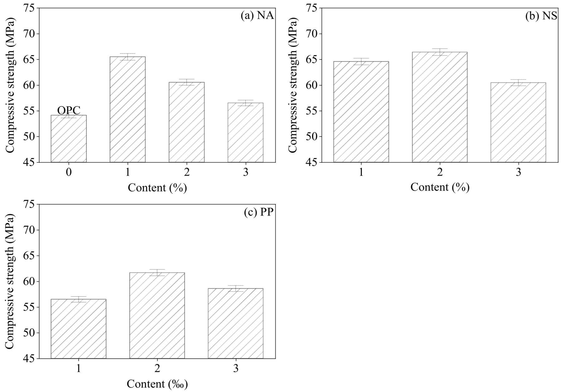
To address this research gap, this study systematically evaluates and compares the frost resistance performance of concrete modified with optimal dosages of nano-alumina (Al2O3), nano-silica (SiO2), and polypropylene fiber (PP), where “optimal dosage” is defined as the content that maximizes mechanical performance. The experimental investigation employed a rapid freeze–thaw cycling apparatus to subject specimens to 300 accelerated durability cycles. Throughout the testing regimen, we quantitatively monitored three key performance indicators: (1) compressive strength evolution, (2) mass loss progression, and (3) elastic modulus degradation. Complementing these macroscopic measurements, X-ray computed tomography (CT) was utilized to characterize the internal structural evolution of concrete specimens both pre- and post-freeze–thaw exposure.
The integrated multi-scale analytical approach—combining macroscopic mechanical testing with microscopic structural characterization—aims to provide novel insights into the comparative frost damage mechanisms of different modification strategies. These findings are expected to fill the existing knowledge gap and offer both fundamental scientific understanding and practical, data-driven guidance for selecting the most effective modifier to develop enhanced frost-resistant concrete formulations for cold-region infrastructure applications.
4. Results and Discussion
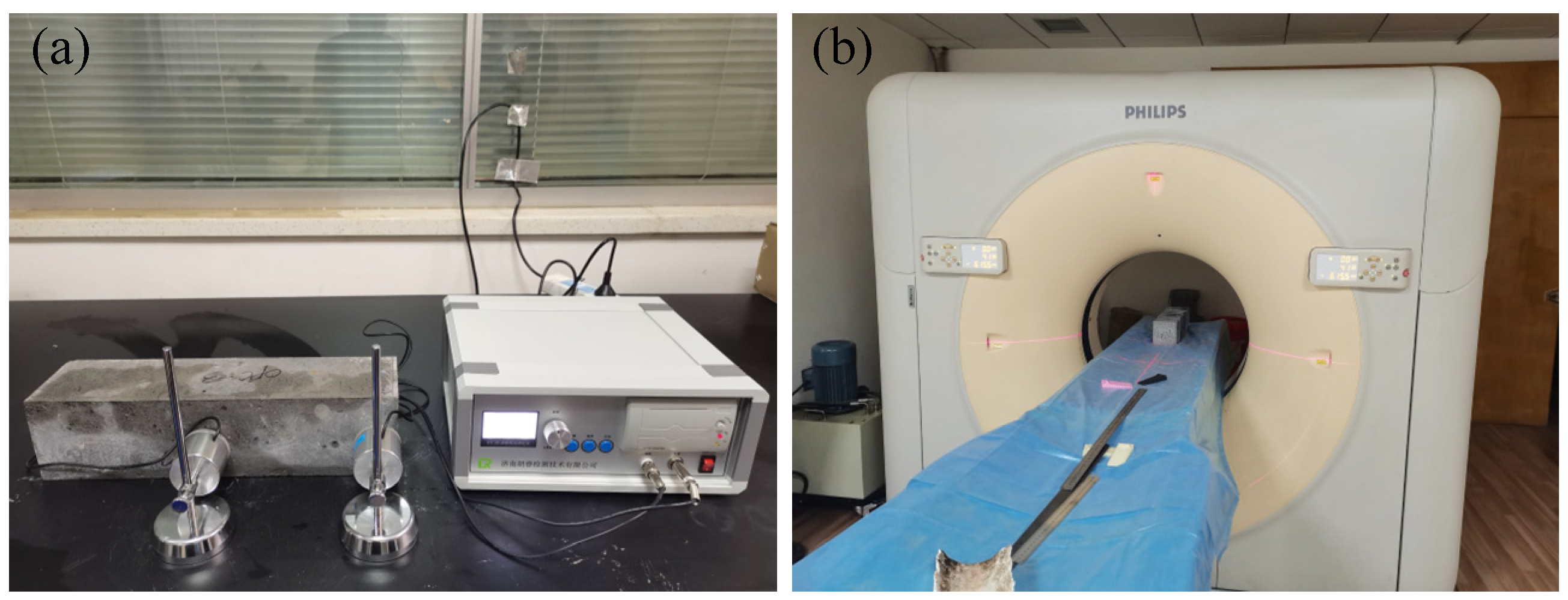
During the rapid freeze–thaw cycling of concrete, the mass, dynamic elastic modulus, and compressive strength of the concrete specimens were tested at different cycle intervals. The specimens tested are 100 mm × 100 mm × 400 mm standard prisms. The mass of the specimen is weighed by an electronic balance. Based on the principle of resonant frequency, the dynamic elastic modulus of the specimen was tested by a dynamic elastic modulus meter (
Figure 5a). Based on computed tomography technology, a CT scanner is used to obtain three-dimensional structural information inside the sample non-destructively (
Figure 5b).
4.1. Mass Loss
As shown in
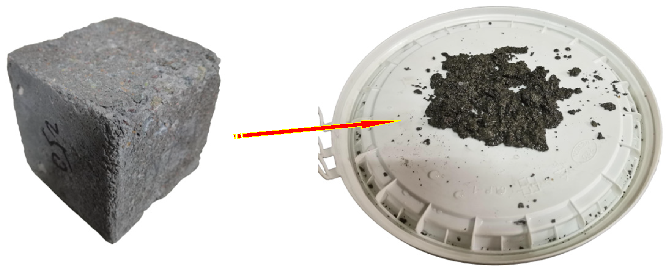
Figure 6, with increasing freeze–thaw cycles, the mortar and fine particles on the surface of the concrete specimens gradually peeled off, exposing the coarse aggregates, leading to mass loss of the samples.
During the cycling process, the mass of the specimens was measured every 25 cycles. The mass loss rate of the specimens was calculated using the following equation:
where
is mass loss rate of concrete specimens (OPC, NA1, NS2, PP2), %;
is initial mass of specimens (OPC, NA1, NS2, PP2) before freeze–thaw cycling, g;
is mass (g) of specimens (OPC, NA1, NS2, PP2) after
N freeze–thaw cycles, g.
The relationship between the mass of concrete specimens and the number of F–T cycles is shown in
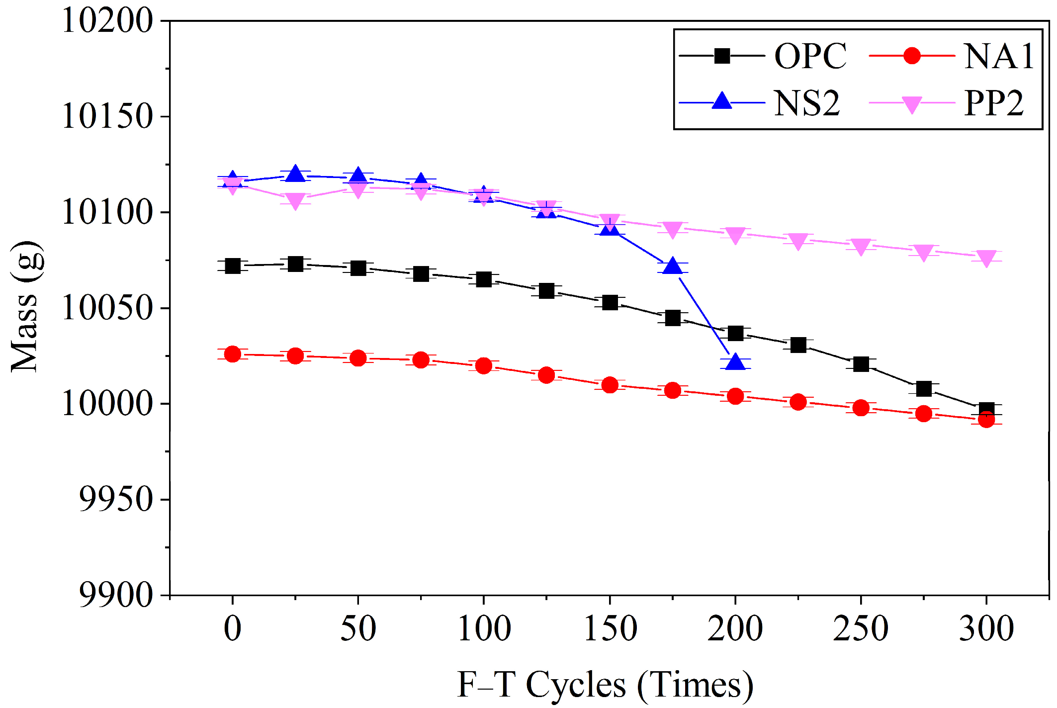
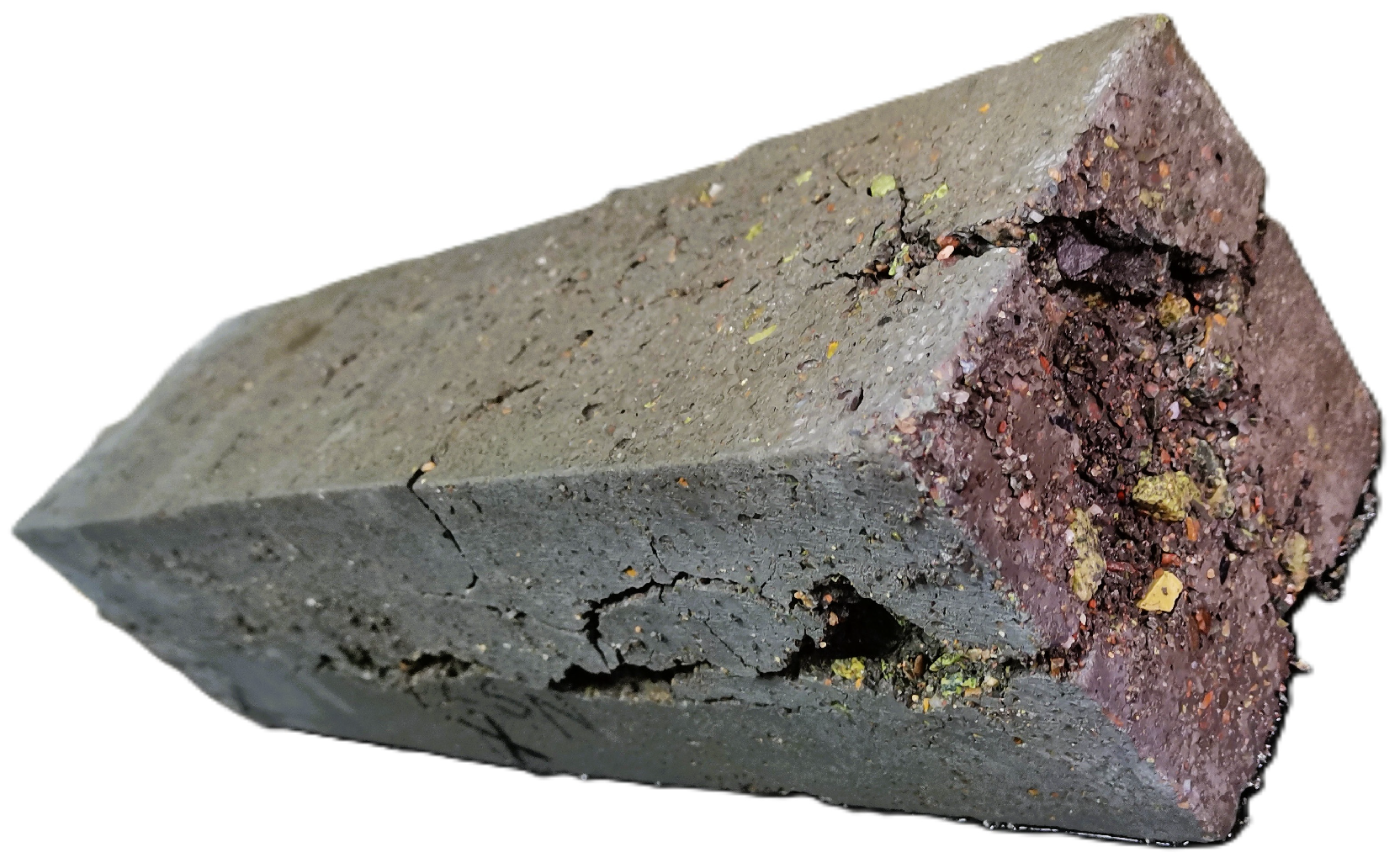
Figure 7. During the F–T cycling process, the specimen mass exhibited a decreasing trend with increasing number of cycles, with this trend becoming more pronounced after 100 cycles. The mass loss was attributed to the detachment of fine cement paste particles and sand grains caused by F–T action, with the amount of detachment increasing progressively with continued cycling. As evident from the figure, specimens NA1 and PP2 demonstrated relatively lower mass loss sensitivity to F–T cycles, followed by OPC, while NS2 exhibited the most significant mass loss among all specimens. After 200 F–T cycles, specimen NS2 experienced structural failure due to F–T damage, as illustrated in
Figure 8. The failure analysis revealed that the F–T action not only caused surface scaling and spalling but also severely compromised the specimen’s internal microstructure. Notably, NS2’s failure manifested primarily as internal structural damage rather than significant surface particle loss. This suggests that while surface spalling is a visible indicator of freeze–thaw damage, the most critical deterioration occurs internally. In contrast, specimen OPC maintained structural integrity but exhibited rapid mass loss, indicating it was still significantly affected by freeze–thaw cycles despite not reaching complete failure.
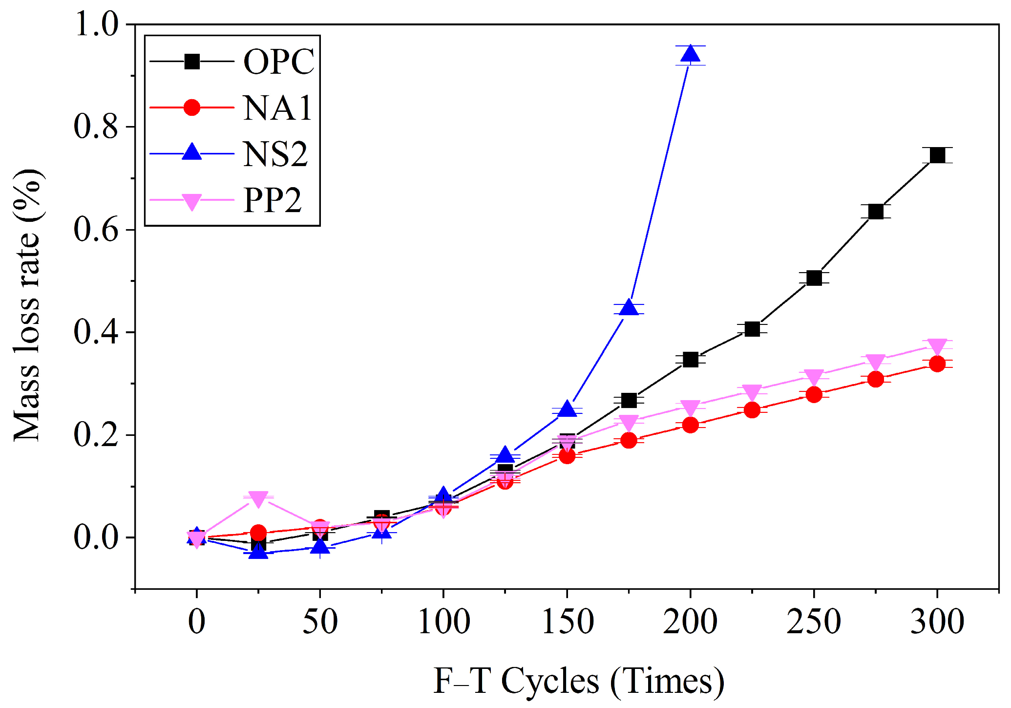
The mass loss rates of specimens during freeze–thaw cycling were calculated according to the given equation, with results presented in
Figure 9. The mass loss rate of specimen NS2 at failure was 0.95%, while those of OPC, NA1, and PP2 after 300 cycles reached 0.75%, 0.36%, and 0.39%, respectively. Notably, all specimens exhibited remarkably low mass loss rates (<1%), significantly below the standard’s 5% termination threshold, revealing three key findings: (1) while mass loss rate alone cannot reliably predict structural failure, it remains a valuable indicator of surface deterioration (particle detachment/aggregate exposure) in intact specimens; (2) the minimal mass loss suggests internal damage mechanisms dominate the failure process; and (3) the substantial margin below the 5% threshold indicates the standard’s conservative nature for these materials, particularly as higher mass loss rates clearly correlate with more severe surface damage from freeze–thaw action.
4.2. Dynamic Elastic Modulus
The dynamic elastic modulus test is a non-destructive method for evaluating concrete’s elastic properties through dynamic response analysis. When specimen dimensions and material composition remain constant, the natural resonant frequency depends solely on material density. Since density correlates with strength, a relationship can be established between resonant frequency and mechanical strength. By measuring the resonant frequency using a concrete dynamic modulus tester, the mechanical strength properties can be determined.
In freeze–thaw testing, dynamic elastic modulus serves as a fundamental indicator for assessing concrete’s frost resistance durability. The dynamic modulus tester was manufactured by Jinan Langrui Testing Co., Ltd., Jinan, China. The dynamic elastic modulus of concrete specimens changes upon freeze–thaw damage, making it a viable parameter for assessing frost deterioration. Tests were conducted on 100 × 100 × 400 mm3 specimens, with measurements taken every 25 freeze–thaw cycles. According to testing standards, concrete is considered to have failed under freeze–thaw cycling when its relative dynamic elastic modulus drops below 60%. The calculations are performed as follows:
Dynamic Elastic Modulus Calculation:
where
is the dynamic elastic modulus of concrete (GPa), m is the mass of the specimen (g),
f is the fundamental vibration frequency (Hz),
l is the longitudinal length of the specimen (mm),
a is the transverse edge length of the specimen (mm).
Relative Dynamic Elastic Modulus Calculation:
where
is relative dynamic elastic modulus (%),
is initial dynamic elastic modulus before cycling (GPa),
is dynamic elastic modulus after
N freeze–thaw cycles (GPa).
As shown in
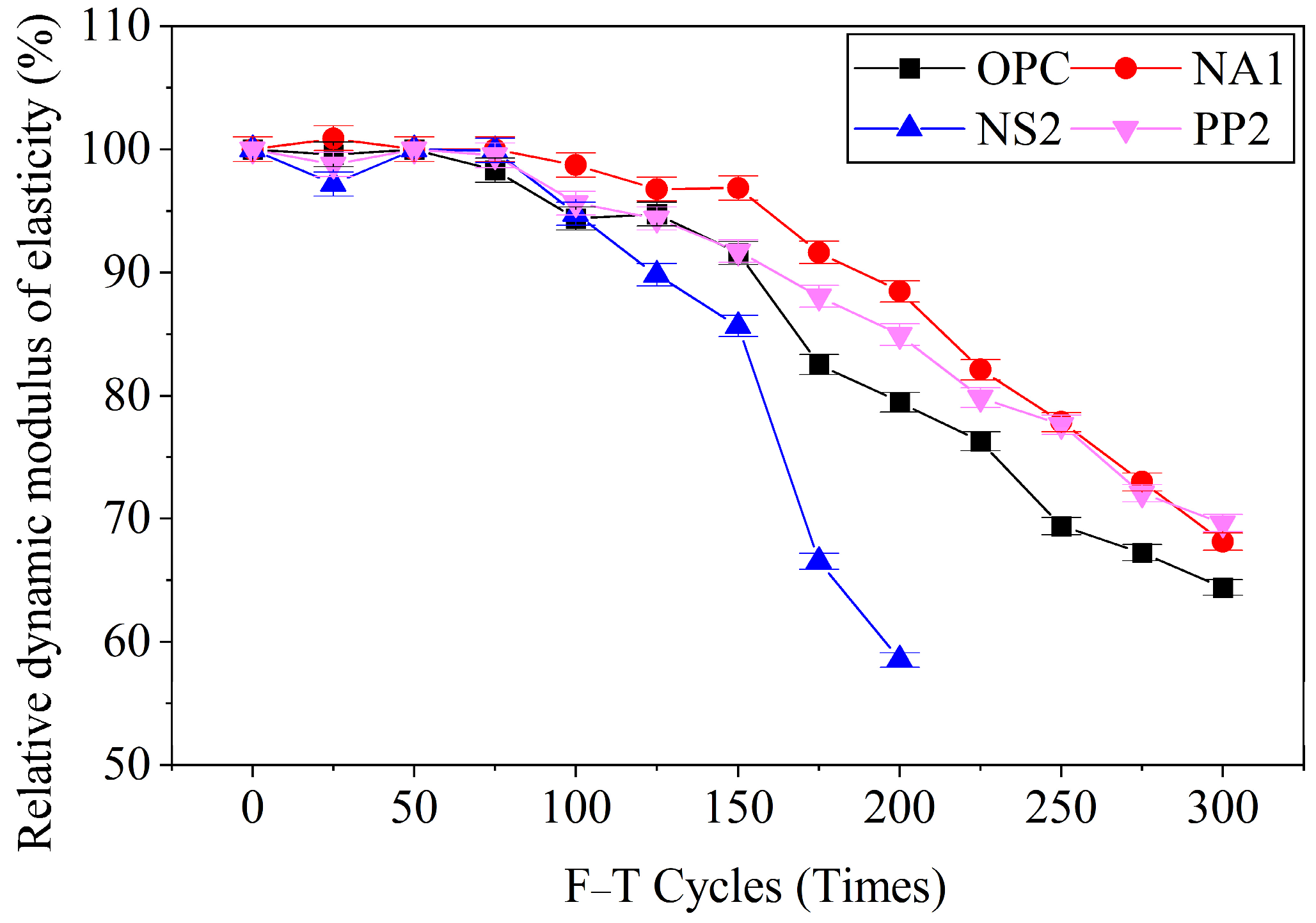
Figure 10, after 300 freeze–thaw cycles, the relative dynamic elastic moduli of specimens OPC, NA1, and PP2 were 64%, 68%, and 70%, respectively. Specimen NS2 failed at 200 cycles with a relative dynamic elastic modulus of 58%, which satisfies the evaluation criterion that defines failure when the value drops below 60%. The experimental results demonstrate that the relative dynamic elastic modulus of concrete decreases with increasing freeze–thaw cycles. This deterioration occurs because the freeze–thaw process continuously generates internal pores and microcracks, progressively reducing the structural density of the concrete. Comparative analysis of the 300-cycle results reveals a clear performance hierarchy: conventional concrete (OPC) showed the most significant modulus reduction (64%), nano-alumina-modified concrete (NA1) exhibited intermediate durability (68%), while polypropylene fiber-reinforced concrete (PP2) demonstrated superior performance (70% retention). This progression conclusively demonstrates that both 1% nano-alumina and 0.2% polypropylene fibers effectively inhibit pore and microcrack development during freeze–thaw cycling, with the fibrous reinforcement system in PP2 providing notably greater durability enhancement than NA1’s particulate modification approach, attributable to the fibers’ superior crack-bridging capability and stress redistribution mechanism.
The evaluation results of the relative dynamic elastic modulus (RDME) in
Table 4 demonstrate a strong correlation with the compressive strength of the lower specimen section, showing that higher relative compressive strength values correspond to elevated RDME values while significant strength reductions lead to proportional RDME declines, with specimen failure consistently occurring when RDME falls below 60%. This parallel behavior confirms RDME as a robust frost resistance evaluation metric since it not only precisely quantifies internal damage accumulation through modulus reduction but also exhibits strong alignment with physical failure patterns and effectively detects performance variations from material modifications, with its consistent adherence to the 60% failure threshold further validating its reliability for concrete durability assessment.
4.3. Compressive Strength
Compressive strength is the most intuitive indicator for evaluating the mechanical properties of concrete and one of the primary metrics for assessing its frost resistance durability. Destructive tensile strength tests were conducted on all specimens every 50 freeze–thaw cycles.
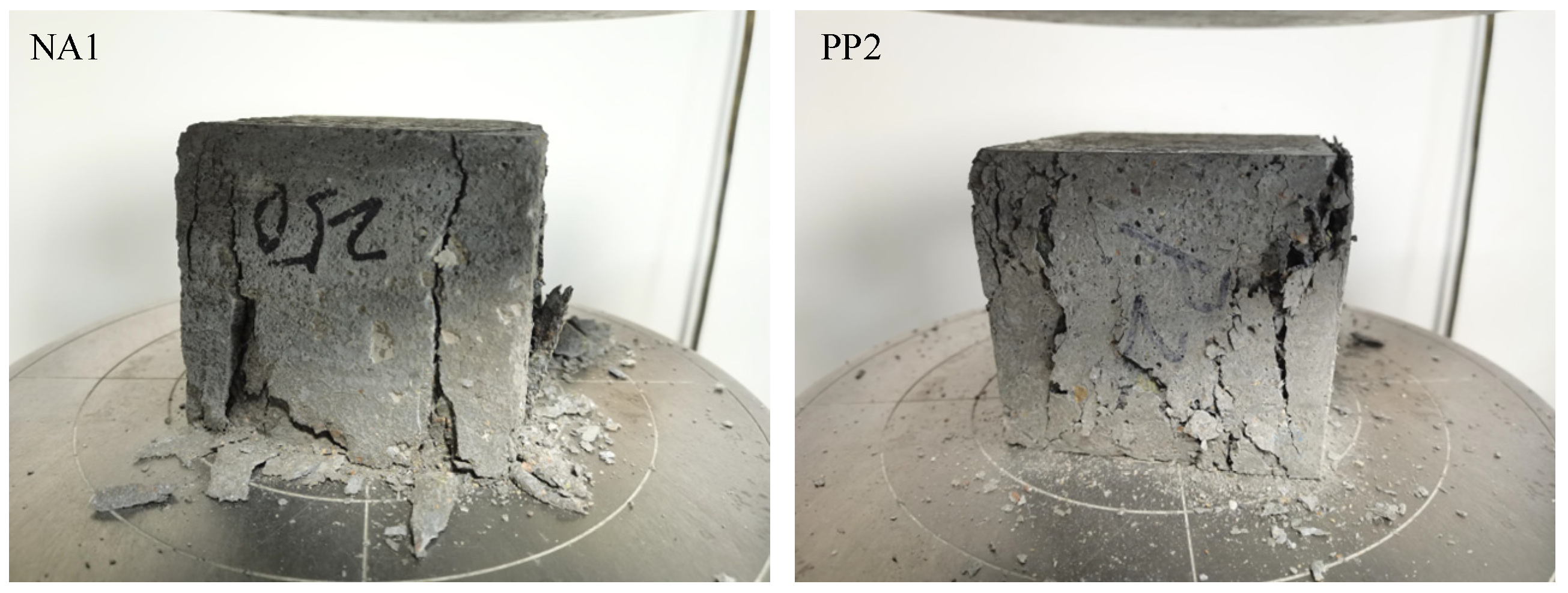
Figure 11 shows the failure state of specimens NA1 and PP2 after 250 cycles. Concrete is a brittle material, and its failure typically results in penetrating cracks. As seen in the figure, the failure modes of specimens NA1 and PP2 differ slightly. Due to the bridging effect of polypropylene fibers, specimen PP2 significantly enhances the tensile strength of the concrete, effectively resisting frost-induced expansion forces. Consequently, no penetrating cracks formed after failure, and the specimen maintained relatively good integrity. This is also the main reason why polypropylene fibers improve the frost resistance durability of concrete.
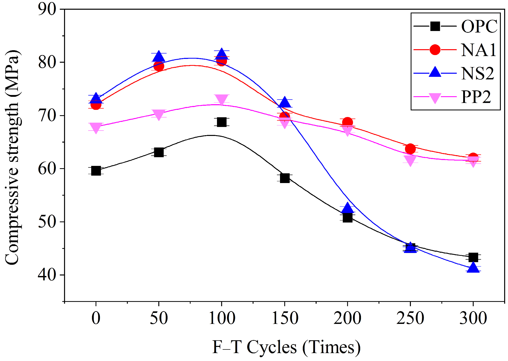
As shown in
Figure 12, the compressive strength values of the specimens were measured after 0, 50, 100, 150, 200, 250, and 300 freeze–thaw cycles. The results indicate that the compressive strength of all specimens initially increased and then decreased with the number of freeze–thaw cycles. It is well known that freeze–thaw cycles have detrimental effects on the durability of concrete, including its mechanical properties. The initial increase in compressive strength before 100 freeze–thaw cycles can be attributed to the fact that the specimens used for the test had an age of only 28 days at the start of the experiment. At this stage, the concrete was still undergoing strength development, and the increase in strength outweighed the damage caused by freeze–thaw cycles.
After 100 freeze–thaw cycles, the compressive strength decreased rapidly, indicating that the adverse effects of freeze–thaw action had become significant. As seen in the figure, the negative impact of freeze–thaw cycles on specimens OPC and NS2 was much greater than on specimens NA1 and PP2. Although the 100 × 100 × 400 mm3 specimen of NS2 failed after 200 cycles, the 100 × 100 × 100 mm3 specimen, despite severe surface scaling, still retained some compressive resistance, with a strength slightly comparable to that of specimen OPC. In contrast, the compressive strength of specimens NA1 and PP2 exhibited a slower decline with increasing freeze–thaw cycles, demonstrating that nano-alumina (NA) and polypropylene fiber (PP) effectively enhanced the frost resistance and durability of the concrete.
To quantitatively analyze the attenuation of compressive strength in concrete specimens during freeze–thaw cycles, the compressive strength attenuation rate was calculated using the following equation:
where
is the compressive strength attenuation rate of specimens OPC, NA1, NS2, and PP2, %;
is the compressive strength of specimens OPC, NA1, NS2, and PP2 after
N freeze–thaw cycles, MPa;
is the initial compressive strength of specimens OPC, NA1, NS2, and PP2 before freeze–thaw cycling, MPa.
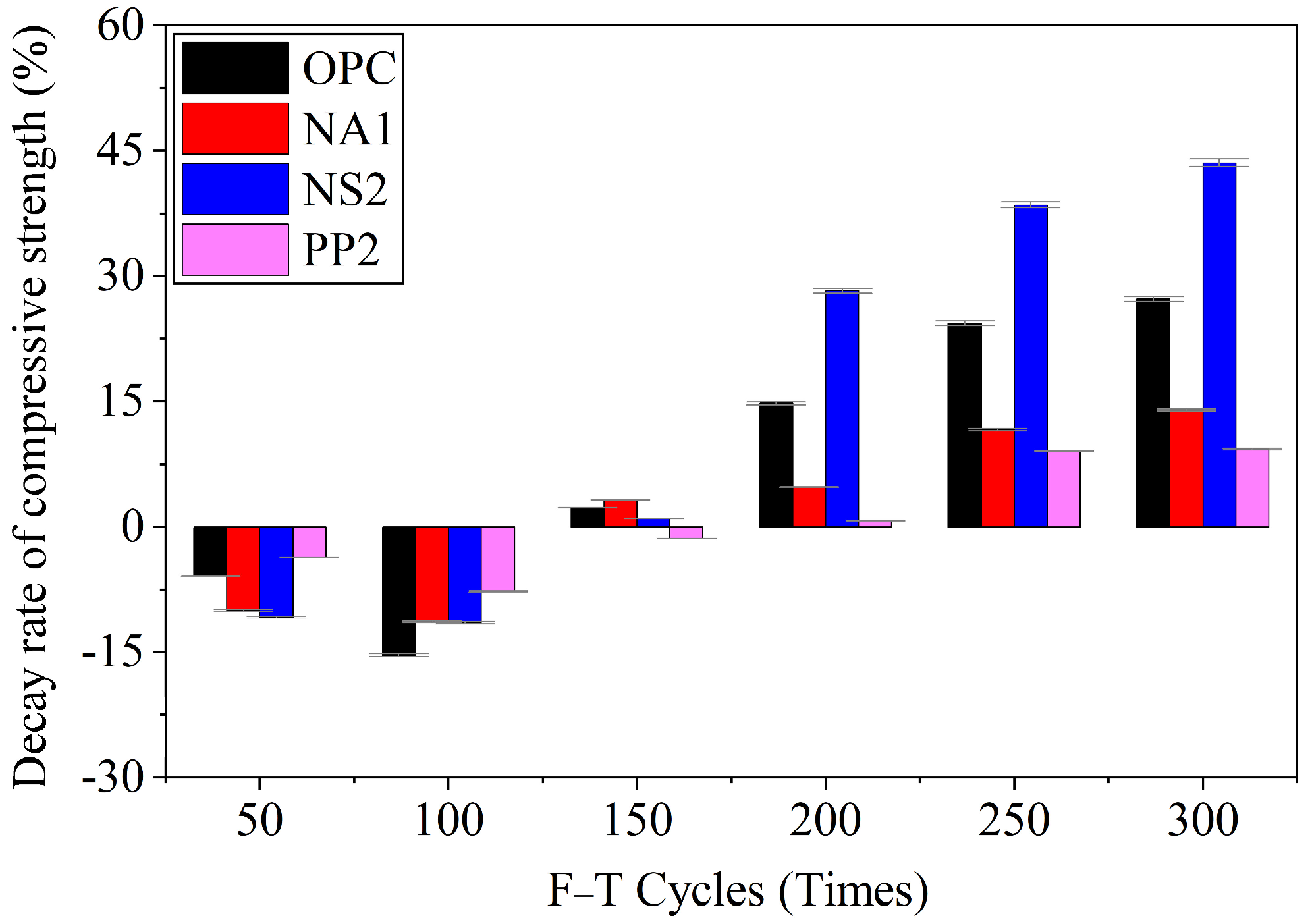
Figure 13 demonstrates the evolution of compressive strength attenuation rate with increasing freeze–thaw cycles, revealing three distinct performance phases. During the initial 100 cycles, all specimens exhibited strength enhancement up to 15%, with OPC showing the most pronounced improvement. Beyond this threshold, compressive strength progressively declined, with attenuation rates escalating with cycle numbers. After 300 cycles, the specimens displayed markedly different durability performance: NS2 suffered the most severe deterioration (43.6% strength loss), followed by OPC (27.3%), while NA1 and PP2 maintained better integrity with only 13.9% and 9.3% reductions, respectively. These results clearly demonstrate the superior frost resistance of polypropylene fiber-reinforced (PP2) and nano-alumina-modified (NA1) concrete compared to conventional (OPC) and nano-silica-modified (NS2) specimens, highlighting the critical influence of material composition on freeze–thaw durability. While nano-silica shows negligible improvement in compressive strength, with its 300-cycle freeze–thaw strength being nearly equivalent to that of ordinary Portland cement (OPC) concrete. This phenomenon can be attributed to the fact that the primary destructive force during rapid freeze–thaw cycles stems from the expansion pressure generated by water freezing in pores and cracks—the greater the porosity, the stronger the expansion force.
Although both nano-silica and nano-alumina theoretically should improve frost resistance by densifying the concrete structure through pore-filling and hydration promotion, thereby reducing ice formation pressure, nano-silica exhibits the opposite behavior. While it demonstrates higher compressive strength during short-term freeze–thaw exposure, its strength deteriorates dramatically after prolonged cycling. This counterintuitive performance is likely due to the specific dosage and unique characteristics of nano-silica particles. The nano-silica particles possess an exceptionally large specific surface area with strong surface forces that adsorb significant amounts of free water. When incorporated in substantial quantities, this results in excessive absorption of mixing water by the nano-silica, consequently impairing the workability of the concrete mixture. This poor workability leads to the formation of numerous capillary pores in the cast NS2 specimens. These capillary pores subsequently serve as nucleation sites for ice formation during freeze–thaw cycles, causing substantial expansion pressure from water freezing in NS2 specimens after prolonged exposure, which rapidly accelerates frost damage. The experimental findings demonstrate that while nanomaterials can indeed enhance the frost resistance of concrete, their effectiveness depends on selecting appropriate types and dosages, as exemplified by nano-alumina. Polypropylene fibers exhibit particularly outstanding advantages in improving concrete’s freeze–thaw durability. Their cost-effectiveness makes them highly suitable for widespread application in concrete engineering projects located in cold regions.
4.4. Structural Damage
Under freeze–thaw cycling, concrete exhibits progressive surface deterioration that clearly reflects its internal structural damage. Initially, small pits appear on the surface, followed by gradual enlargement of these pits with exposed fine aggregates as cycling continues. With increasing freeze–thaw cycles, more severe damage occurs, including spalling of cementitious materials, loss of fine aggregates, and eventually prominent exposure of coarse aggregates. This visible damage progression—from minor pitting to significant material loss—directly correlates with the internal microstructural deterioration caused by repeated ice formation and expansion in concrete pores and microcracks. The surface degradation pattern serves as a reliable indicator of freeze–thaw induced damage development in concrete structures.
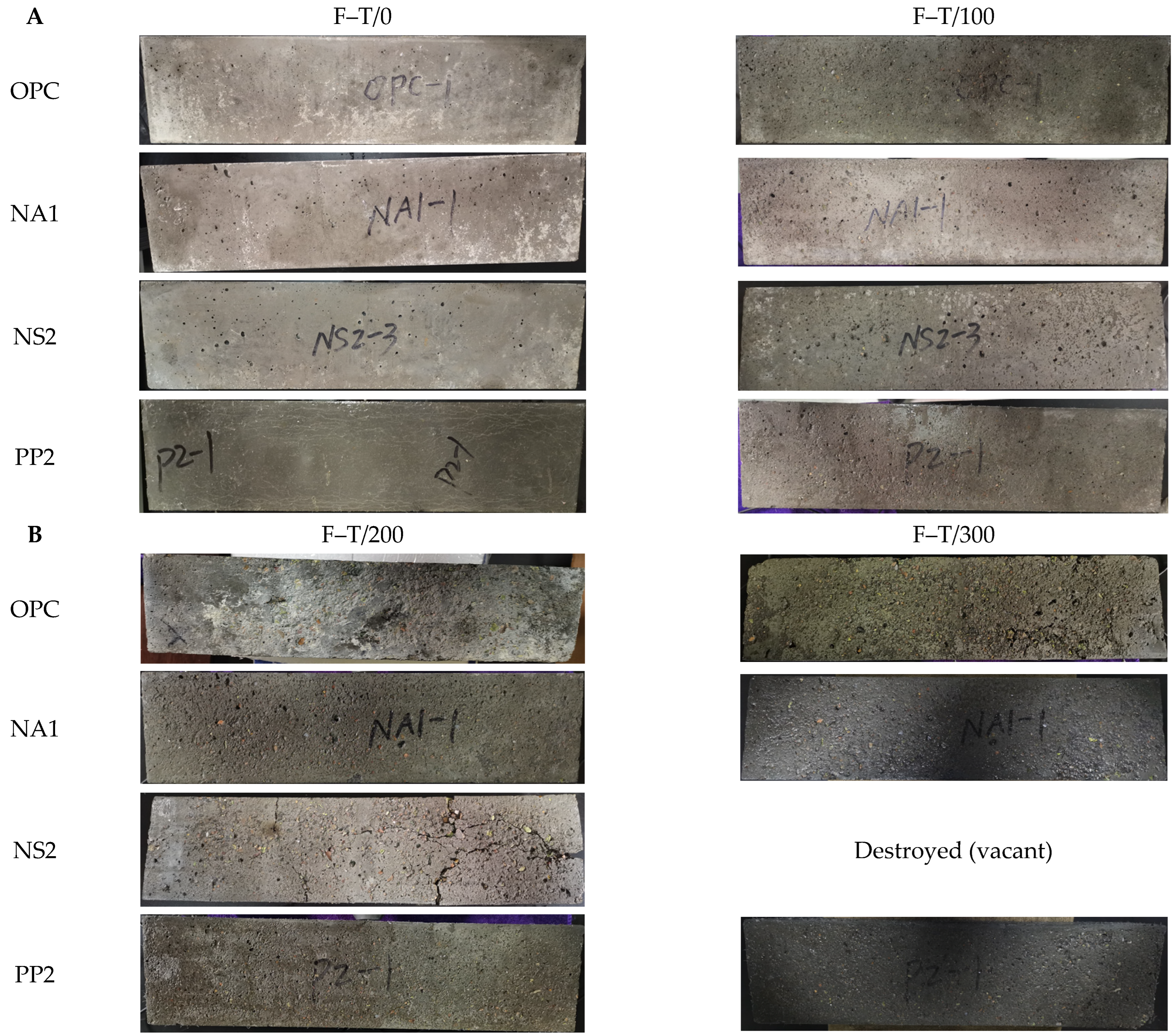
Figure 14 clearly illustrates the progressive surface deterioration of concrete specimens under freeze–thaw cycling. The control specimen (OPC) showed typical damage progression: initial surface pitting at 100 cycles, significant mortar and fine aggregate loss exposing coarse aggregates at 200 cycles, and severe structural damage with macrocracks and edge spalling after 300 cycles. Notably, the NS2 specimen with nano-silica exhibited accelerated deterioration, developing extensive cracking networks that led to structural failure by 200 cycles. In contrast, both NA1 (nano-alumina) and PP2 (polypropylene fiber) specimens demonstrated superior frost resistance—while showing some mortar loss and initial aggregate exposure after 300 cycles, they maintained structural integrity without cracking. These visual observations correlate well with mechanical test results, confirming that nano-alumina modification and fiber reinforcement can effectively mitigate freeze–thaw damage in concrete structures.
The experimental results demonstrate distinct effects of different additives on concrete’s freeze–thaw resistance. All specimens eventually showed characteristic deterioration patterns including mortar loss, fine aggregate shedding, coarse aggregate exposure, and crack formation. Comparative analysis reveals that nano-silica (NS2) adversely affected durability, causing premature structural failure before completing 300 cycles. Conversely, both nano-alumina (NA1) and polypropylene fiber (PP2) significantly improved performance—while exhibiting surface mortar loss and aggregate exposure similar to ordinary concrete (OPC), they effectively prevented structural cracking. This superior performance aligns with previous mechanistic analysis (discussed in prior sections), confirming these additives’ beneficial role in enhancing concrete’s frost resistance without compromising structural integrity.
4.5. Internal Characteristics
Concrete is an artificially manufactured construction material, a composite formed by the bonding of cement paste with sand and aggregate. During the pouring process, initial damage such as micro-pores and microcracks is generated inside. Under freeze–thaw cycles, this initial damage continuously expands, ultimately leading to the failure of the concrete material. In freeze–thaw environments, pores are the source of frost heave forces, and the continuous evolution of pore structure is the intrinsic manifestation of the concrete damage process. CT scanning is a non-destructive testing method that can track changes in the pore structure of concrete during freeze–thaw cycles, thereby establishing a connection between internal structure and macroscopic performance to assess the extent of concrete damage.
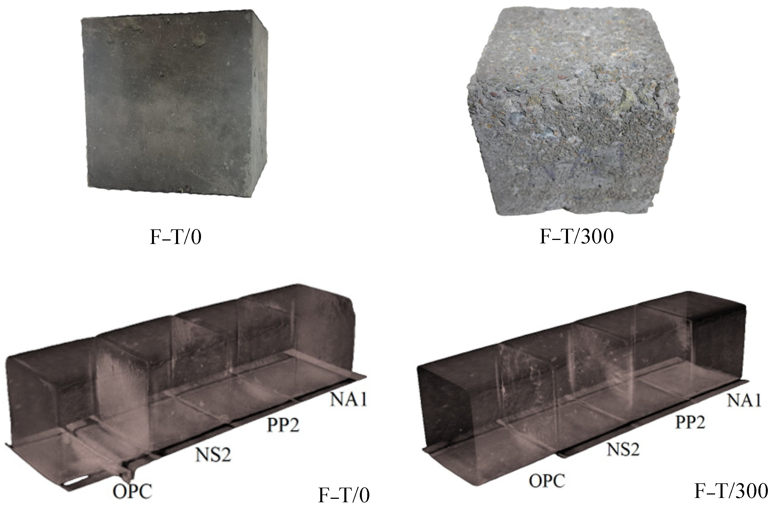
Concrete is a cementitious material composed of paste, fine aggregate, and coarse aggregate, with a complex internal structure. During freeze–thaw cycles, pores and microcracks develop within its structure, which are generally invisible to the naked eye. Therefore, X-ray computed tomography (CT) was used to scan cross-sections of the concrete, as shown in
Figure 5b. Four specimens—OPC, NA1, NS2, and PP2, each measuring 100 × 100 × 100 mm
3—were subjected to CT scanning before and after 300 freeze–thaw cycles. The grayscale image data obtained from these scans were analyzed to examine the fundamental characteristics of the images before and after freeze–thaw exposure.
Figure 15 shows the CT scan images of concrete specimens OPC, NS2, PP2, and NA1 before and after 300 freeze–thaw cycles. The scan images reveal that pores exist in the internal structure of the specimens before freeze–thaw exposure, indicating initial damage. Specimens OPC and PP2 exhibit very few pores, while NS2 contains a significant number of pores, and NA1 appears almost pore-free. In reality, all specimens should contain pores, but smaller pores may not be visible in the CT images. Based on pore size, pores can be classified into gel pores, capillary pores, and macropores. The CT images primarily display macropores and a small portion of capillary pores. Capillary and macropores are considered harmful—capillary pores are unavoidable as they form during hydration, whereas macropores result from poor casting techniques and can be minimized. The large number of macropores observed in specimen NS2 is mainly attributed to the dosage and characteristics of nano-silica (NS). Due to its extremely high specific surface area, nano-silica adsorbs a substantial amount of free water. Combined with its high dosage, this leads to poor workability of the concrete mixture, resulting in the formation of numerous macro-pores during casting.
In contrast, specimen NA1 shows almost no pores in the CT images due to the incorporation of nano-alumina (NA). Nano-alumina contributes to pore-filling, nucleation, and pozzolanic effects, significantly reducing harmful pores in the cast concrete. After 300 freeze–thaw cycles, the pores in specimen NS2 expanded substantially, while those in OPC and PP2 increased slightly. Specimen NA1 exhibited almost no change in pore structure. This indicates that specimens with severe initial damage are more susceptible to deterioration during freeze–thaw cycling. The presence of initial harmful pores provides favorable sites for frost heave forces, accelerating freeze–thaw damage. Conversely, specimens with minimal initial harmful pores exhibit strong frost resistance. Due to its low total porosity and minor initial damage, specimen NA1’s internal structure remains resistant to frost-induced damage.
Although freeze–thaw cycles cause obvious external deterioration—such as mortar flaking, sand loss, edge spalling, and aggregate exposure—these alone do not necessarily lead to functional failure. The results demonstrate that freeze–thaw damage in concrete is primarily driven by internal structural deterioration, with external damage being merely a superficial manifestation. The experimental findings suggest that improving the frost durability of concrete relies on enhancing its compactness, minimizing micro-pores and microcracks, and reducing initial damage
5. Conclusions
Through comprehensive analysis of concrete specimens subjected to 300 accelerated freeze–thaw cycles, the following conclusions are obtained:
(1) Experimental results demonstrate that nano-alumina (1% dosage) and polypropylene fiber (PP) fiber (0.2% dosage) significantly enhance concrete’s frost resistance, while nano-silica (2% dosage) shows limited improvement. PP fibers emerge as the superior modifier due to their four key advantages: lower effective dosage requirement, easier mixing and processing, better cost/performance ratio, and more consistent durability enhancement across freeze–thaw cycles.
(2) Under cyclic freezing conditions, concrete exhibits progressive deterioration through measurable mass loss, dynamic elastic modulus reduction, and compressive strength decline. These macroscopic changes correlate directly with internal microstructural damage, making compressive strength the most reliable indicator of structural integrity loss.
(3) Frost damage initiates internally through microcrack propagation and pore network expansion at pre-existing defects. Surface spalling represents only the final, visible stage of this underlying microstructural breakdown. This fundamental understanding confirms that enhancing internal structure is crucial for durable frost-resistant concrete.
Based on the findings of this study, several directions for future work are recommended. While polypropylene fiber (PP) proved most optimal among the materials tested, its performance should be further compared with other fibrous materials, such as carbon, basalt, and aramid fibers, to comprehensively evaluate their effectiveness in enhancing frost resistance. Future investigations will focus on the comparative impact of these advanced fibers on the material’s durability and long-term performance under freeze–thaw cycles.

