Abstract
Iron aluminides possess a unique combination of properties such as attractive corrosion resistance in hot gas and wet chemical environments, a favorable strength to weight ratio, low costs of alloying elements, and they can be processed by conventional methods. For the current study, a promising iron aluminide (Fe-Al-Mo-Ti-B) was employed, which shows the potential to replace costly heat resistant steels or expensive Ni-based alloys for components in large bore two-stroke marine engines. The prechamber, an integral part of the combustion system of dual fuel two-stroke marine engines, which must withstand harsh conditions, was selected as the component. Prototypes made of the novel iron aluminide were manufactured via investment casting and hot isostatic pressing using powder of the intermetallic alloy. The high temperature oxidation behavior, the wet corrosion resistance in acid media, and the mechanical properties up to 700 °C were evaluated. A prototype of the prechamber was tested on a large bore two-stroke dual fuel test engine and post analysis of the tested component was performed. The results show that the employed iron aluminide alloy could be an economic alternative to the currently used Ni-based alloy.
1. Introduction
There exits an increasing demand in marine engines for new suitable materials facing the need for higher performance, new fuels or lower emissions, and also a continuous pressure to reduce costs [1]. Iron aluminides with their excellent hot corrosion (oxidation, sulfidation) behavior, high wear resistance, their low cost of alloying elements, and their good processability are considered as promising candidate materials [2,3,4].
Driven by the stringent exhaust gas regulations [5] and an ever-growing demand for sustainability in the marine industry, new engines are constantly developed. Besides reduced emissions, operating them with alternative fuels, e.g., a mix of natural gas and volatile organic compounds or biofuels obtained from lignin, are evaluated. In this regard, X-dual fuel (X-DF) engines with liquid natural gas (LNG) as the main fuel and low pressure gas technology have been successfully introduced in 2013 for low-speed, large bore two-stroke engines [6]. This also marks a radical change in merchant shipping industry as heavy fuel oil was used as sole fuel for more than a century. X-DF engines are capable to either use diesel (diesel mode) or natural gas (gas mode) as fuel. However, the X-DF engines are intended to mainly operate in gas mode as the NOx, SOx, CO2 and particle matter emissions are substantially reduced compared to engines running on heavy fuel oil [7]. The X-DF technology is based on the lean-burn Otto-cycle combustion. The natural gas is admitted at low pressure in the combustion chamber and is ignited by injection a low volume of liquid fuel in the prechamber (Figure 1a). The prechamber is the lowest part of the pilot fuel injector (Figure 1b), which has the function of a spark plug compared to smaller sized engines. The prechamber has to withstand high thermal loads and is exposed to hot gases from combustion. Currently it is made from an expensive Ni-based superalloy (NIMONIC® Alloy 80A, 2.4631) and machined from complete bars in a rather time consuming, tool intensive and hence costly process.
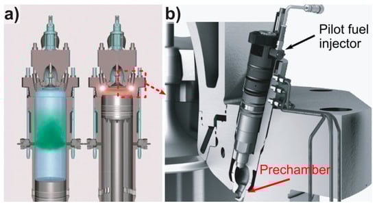
Figure 1.
(a) The X-dual fuel (X-DF) working principle with gas admission during up-stroke (left) and ignition of the compressed fuel/air mix through the prechamber (right); (b) close up of the X-DF pilot injector indicating the position of the prechamber; [7].
Iron aluminides are Fe-based alloys containing between 20 to 50 at. % Al. Depending on Al content they are either based on the intermetallic phase Fe3Al or FeAl. They exhibit a disorder-order transformation in the solid state upon cooling resulting in the ordered B2 (FeAl) and D03 (Fe3Al) structure [8]. The superior hot gas resistance, crucial for applications in the combustion system, of iron aluminides is attributed to the formation of a protective oxide (alumina) layer when exposed to elevated temperatures [9,10,11]. Moreover, good resistance in carburizing atmospheres and molten salts have been reported [3,12]. Processing routes similar to that used for steels, i.e., conventional casting, rolling, and forging as well as standard machining equipment can be applied for manufacturing [4,12,13,14]. Also, novel processing routes such as additive manufacturing using selective laser melting or laser metal deposition have been successfully employed [15,16]. Besides the numerous advantages of iron aluminides, some disadvantages such as their low ductility at ambient temperature as well as their lack of sufficient strength at high temperatures (i.e., ≈600 °C) has limited their application. A lot of research has focused to overcome these drawbacks, e.g., via using thermal-mechanical treatments to improve ductility or to increase strength by various alloying strategies [17,18,19,20,21]. In this regard, recently a promising Fe-Al based alloy on the basis of Fe3Al with minor addition of Mo, Ti, B has been developed, which exhibits a favorably low ductile-to-brittle transition temperature (DBTT) and a high creep strength at 650 °C [22].
The current work covers the evaluation of basic material properties of a promising quinary Fe-Al-Mo-Ti-B alloy and its application in the combustion chamber of large bore two-stroke engines. Prototypes of the prechamber made of the Fe-Al-Mo-Ti-B alloy were manufactured via investment casting, which offers the economically attractive opportunity to produce near-net shape components. In addition, hot isostatic pressing (HIP) using powder of the Fe-Al-Mo-Ti-B alloy was employed as alternative processing route. The microstructures of the as-cast and the HIP-version were analyzed. The oxidation behavior, wet corrosion resistance in acid media, and the mechanical properties at elevated temperature were investigated in lab tests. A prototype of the prechamber made of the Fe-Al-Mo-Ti-B alloy was tested on a large bore two-stroke dual fuel test engine for a total of 61 running hours (rhr) and results from the post analysis of the tested prechamber are presented.
2. Materials and Methods
2.1. Processing of Material for Lab Tests and Prototype Manufacturing
Castings of the Fe-Al-Mo-Ti-B alloy were prepared by vacuum induction melting under argon atmosphere and casting into cold copper molds for lab test samples (tensile testing, oxidation experiments, potentiodynamic measurements), or in ceramic shells for prototype manufacturing. The ceramic shells for investment casting were provided by Deloro Wear Solutions GmbH, Koblenz, Germany.
For producing the HIP version of the Fe-Al-Mo-Ti-B alloy, a powder batch of 35 kg was made by gas-atomization at Nanoval GmbH & Co. KG, Berlin, Germany, with a grain fraction ranging from 20 to 150 μm. The HIP process was conducted at Deloro HTM GmbH, Biel, Switzerland. The powder was sealed in a stainless-steel tube (X2CrNiMo17-12-2, 1.4404) and then outgassed. Consolidation of the HIP-material was performed at 1200 °C with a holding time of 4.5 h. Samples for microstructural analysis, tensile testing, and potentiodynamic measurements were cut from the HIP-bar by electrical discharge machining (EDM). Prechamber prototypes were machined from the HIP-bar by Aerotech GmbH, Weisslingen, Switzerland.
The chemical composition of the Fe-Al-Mo-Ti-B alloy prepared by casting and by HIP was measured via wet chemical analysis and the results are listed in Table 1. The compositions of the alloys in the two different states match each other very well.

Table 1.
Measured chemical compositions of the Fe-Al-Mo-Ti-B alloy processed via casting or hot isostatic pressing (HIP).
2.2. Material Characterization
Microstructures were investigated using a scanning electron microscope (SEM, Zeiss Gemini 500, Carl Zeiss AG, Jena, Germany). Post analysis of the tested prechamber was done on a SEM (Zeiss Auriga, Carl Zeiss AG, Jena, Germany) equipped with an energy-dispersive spectrometer (EDS, EDAX Elect plus, EDAX Inc., UT, USA) and compositions of phases were determined with an electron probe micro analyzer (EPMA, JEOL JXA-8100l, JEOL USA, Inc., Peabody, MA, USA). Measurements were performed at 15 kV and 20 nA using pure elements as standards.
Oxidation experiments were performed with samples in the as-cast and HIP conditions as well as with specimens from commercial NIMONIC® 80A. Measurements were conducted under isothermal condition at 900 °C in a thermobalance (Setaram SETSYS 16/18, SETARAM Instrumentation, Caluire, France) in flowing synthetic air (20.5% O2, 79.5% N2) at a flow rate of 1.54 × 10⁻⁶ m3/s. The mass gains of the samples were continuously recorded during the experiments. The oxide scales were characterized by grazing incidence X-ray diffraction (GI-XRD, Seifert ID3003, XRD Eigenmann GmbH, Schnaittach, Germany) using Co-Kα1 radiation (λ = 0.178897 nm) and an incidence angle of 2.0°. The 2θ range 10–130° was scanned in 2θ steps of 0.05° with a count time of 30 s per step.
Aqueous corrosion tests by means of potentiodynamic polarization measurements were conducted at room temperature, in sulphuric acid (H2SO4) with a pH of 1.6 (0.0126M). The three electrode-method was employed for the electrochemical experiments using a Ag/AgCl reference electrode. Potentiodynamic polarization curves were determined in the range −1.5 to 2 V with a scan rate of 1 mV/s.
For tensile stress–strain tests, flat, dog-bone shaped specimens with a gauge length of 20 mm were cut by EDM. Tests were performed between room temperature and 700 °C at a constant strain rate of 10−4 s−1 in air on a universal testing machine (Zwick/Roell ZMART.PRO, Zwick/Roell AG, Ulm, Germany).
Industrial computer tomography (CT) scans of investment cast prechamber prototypes were done at Qualitech AG, Mägerwil, Switzerland, using a CT scanner from YXLON (CT Modular) equipped with a flat panel detector (XRD 1621 AN 18 ES, PerkinElmer Inc., Waltham, MA, USA). The scans were done in cone beam mode at a voltage of 600 kV and a current of 1.1 mA (Y.TU600-D02 X-ray tube).
For post analysis of the pre-chamber after the engine test, sections for metallographic analysis were cut from the pre-chamber and electroless coated with Cu prior embedding.
3. Results and Discussion
3.1. Material Characterization of as-Cast and HIPped Fe-Al-Mo-Ti-B
3.1.1. Microstructure
The microstructure of the Fe-Al-Mo-Ti-B alloy in the as-cast and HIP condition was analyzed via SEM. The images shown in Figure 2 were taken in back-scattered electron (BSE) mode.
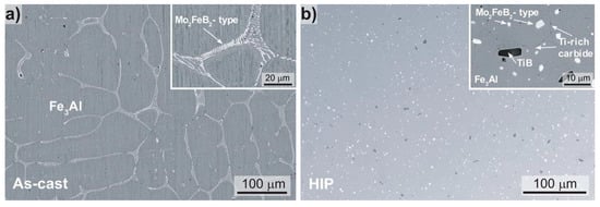
Figure 2.
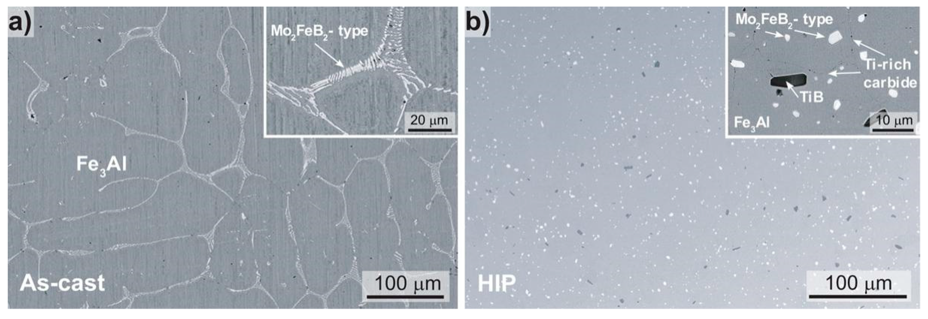
Scanning electron microscope (SEM) images (back-scattered electron (BSE)-mode) of the microstructure of the Fe-Al-Mo-Ti-B alloy in the (a) as-cast (Fe-25.7Al-2.0Mo-0.6Ti-1.3B, in at. %) and (b) the HIP condition (Fe-25.3Al-2.0Mo-0.5Ti-1.4B, in at. %).
The as-cast material (Figure 2a) is characterized by a coarse-grained matrix (grain size > 100 µm) formed by primary dendrites and eutectic seems. For an alloy of comparable composition (Fe-25.5Al-2.1Mo-0.5Ti-1.2B, in at. %) produced with the same equipment Li et al. [22] showed that the matrix is D03-ordered Fe3Al at room temperature, while the eutectic consists of a complex boride of Mo2FeB2-type (light appearing phase in Figure 2) and Fe3Al. The Fe-Al-Mo-Ti-B alloy in the HIP condition (Figure 2b) shows equiaxed Fe3Al with a grain size of about 20 µm with evenly distributed 1–3 µm Mo2FeB2-type borides. In addition, a few larger TiB precipitates and a Ti-rich carbide occurring at the grain boundaries were identified by EPMA (insert Figure 2b). The carbide should have formed during HIPping, when carbon diffused from the stainless steel container into the alloy. The composition of the Fe3Al matrix was established by EPMA as 72.0 ± 0.6 Fe, 26.7 ± 0.5 Al, 1.1 ± 0.1 Mo, 0.2 ± 0.09 Ti (in at. %), which matches that for the as-cast alloy. No pores or voids were revealed indicating that the HIP parameters were sufficient to produce a consolidated bar.
3.1.2. Corrosion Behavior
The oxidation resistance was studied at 900 °C in synthetic air. The oxide growth kinetics in the steady state regime is often rate controlled by diffusion and can be expressed by the following parabolic rate law [23]:
where m0 and mt are the mass in gram in the beginning and at the time t of the experiment; A is the surface area in cm2, t is the time in seconds, and kp is the parabolic rate constant. The rate constant can be used to quantitatively compare the oxidation resistance of different materials. Table 2 lists the measured kp values for the Fe-Al-Mo-Ti-B alloys in the as-cast and HIP condition as well as for Nimonic 80A, which is currently used as prechamber material. The kp values of Fe-Al-Mo-Ti-B in both, as-cast and HIP, conditions are around 2 orders of magnitude smaller than the kp of Nimonic 80A, demonstrating a significant better oxidation resistance. Furthermore, the kp values for Fe-Al-Mo-Ti-B fit well with kp of other α-Al2O3 forming alloys at 900 °C [24].
(mt2 − m02)/A= kp·t
Table 2.
Parabolic rate constants kp measured in synthetic air at 900 °C. The duration specifies the time range used to determine kp.
GI-XRD measurements and SEM investigations were performed to elucidate the oxidation behavior of Fe-Al-Mo-Ti-B. Figure 3 shows results of Fe-Al-Mo-Ti-B in the as-cast condition after oxidation at 900 °C. The peaks in the GI-XRD spectrum (Figure 3a) match to α-Al2O3, Fe2O3 and Ti2.5O3 and to the Fe3Al matrix. In the secondary electron (SE) SEM image of the surface (Figure 3b) protrusions at the grain boundaries, i.e., at the location of the boride, are visible. The surface of the Fe3Al-matrix appears nearly unaffected by oxidation and the grooves from grinding are still clearly visible. Figure 3c shows a BSE-SEM image of a cross-section and corresponding element mappings. A dense, uniform and well adhering Al2O3 scale has formed on the Fe3Al matrix with a thickness of approximately 0.8 μm. The Mo2FeB2-type boride located at the grain boundaries has been preferentially attacked (Figure 3c) and a porous protrusion has formed. The element mappings reveal that the protrusion consists of an outer layer containing Fe, Ti and O, while the remainder consists of Al and O, i.e., Al2O3. The element mappings do not show Mo inside the protrusion, presumably because volatile Mo-oxide form above 700 °C [25].
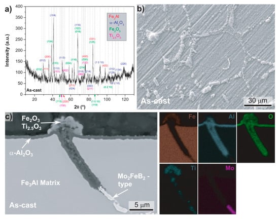
Figure 3.
As-cast Fe-25.7Al-2.0Mo-0.6Ti-1.3B after oxidation at 900 °C in synthetic air; (a) grazing incidence X-ray diffraction (GI-XRD) spectrum; (b) secondary electron (SE)-SEM image of the surface; (c) BSE-SEM image of the cross section and the corresponding energy-dispersive spectrometer (EDS) element mappings.
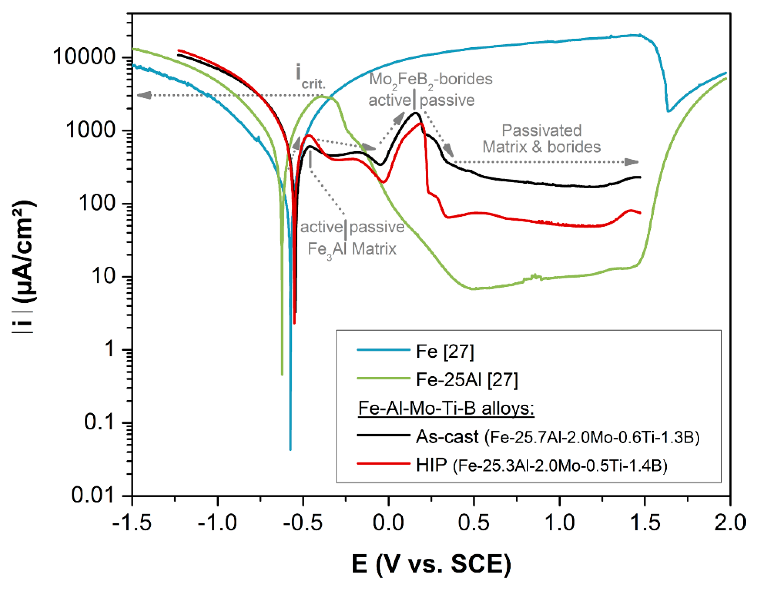
Cold corrosion in marine engines occurs due to the condensation of sulfuric acid. Sulphur within the fuels forms SO3 during combustion, which further on reacts with water to form sulfuric acid [26]. Therefore, aqueous corrosion behavior of Fe-Al-Mo-Ti-B was studied via potentiodynamic measurements in aqueous sulphuric acid (pH = 1.6) at room temperature. Figure 4 displays results for Fe-Al-Mo-Ti-B in the as-cast and HIP condition as well as of pure Fe and of Fe-25Al [27] for comparison. Pure iron (Figure 4) shows a potentiodyanmic curve typical for active metal dissolution in acid media [28]. In contrast, binary Fe-25Al exhibits a curve which is characteristic for passive behavior, i.e., after passing the critical current (icrit) a drop-in current occurs due to passive film formation. As in detail analyzed by X-ray photoelectron spectroscopy [27], the passive film on Fe-25Al consists of an outer layer of mixed Al- and Fe-oxides and an inner layer of hydroxides with an enrichment in Al.

Figure 4.
Potentiodynamic curves measured in sulphuric acid solution (pH = 1.6) at room temperature. Results from pure Fe and binary Fe-25Al are added for comparison [27].
For Fe-Al-Mo-Ti-B in the as-cast and HIP condition the potentiodynamic curves have a very similar shape (Figure 4). They exhibit an active to passive transition at voltages similar to binary Fe-25, i.e., indicating the formation of a passivation layer on the Fe3Al-matrix of Fe-Al-Mo-Ti-B. However, compared to binary Fe-25Al the critical current is significantly lower. For stainless steels and also for iron aluminides it is known that alloying with Mo increases passivity [28,29,30]. Therefore, the markedly decreased critical current, and hence the facilitated passive layer formation is ascribed to the addition of Mo. A pronounced anodic peak is apparent in the potentiodynamic curves of both Fe-Al-Mo-Ti-B samples, but not for Fe-25Al (Figure 4). The occurrence of such a peak indicates, that there are sites, which upon increasing the voltage act actively, leading to an increase in current, and the drop in current upon further voltage increase indicates a passivation of these sites. A similar behavior has been observed for Ni3Al bonded TiC-based cermets measured in 1M H2SO4 [31]. The anodic peak has been related to the TiC-phase and its active/passive transition [31]. Hence it is suggested that the anodic peak in Fe-Al-Mo-Ti-B is related to the active/passive transition of the Mo2FeB2-type boride.
3.1.3. Mechanical Behavior
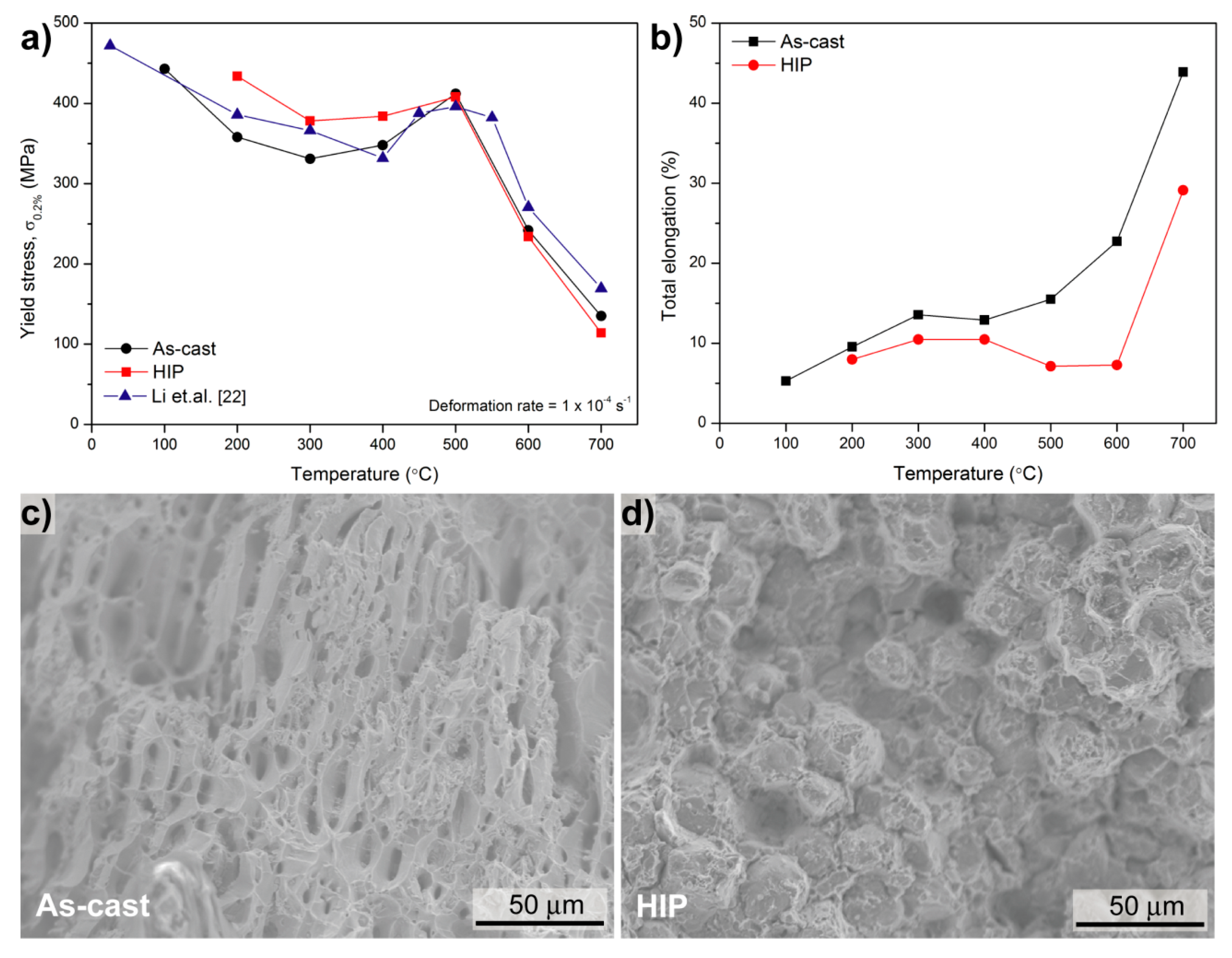
Figure 5a shows the 0.2% tensile yield stress of the as-cast and HIPped alloys as a function of temperature. The compressive 0.2% yield stress of an alloy with comparable composition (Fe-25.5Al-2.1Mo-0.5Ti-1.2B, in at. %) is also shown [22]. The yield stress of all three alloys decreases with increasing temperature before reaching a maximum of about 400 MPa at 500 °C. Such an increase of the yield stress at intermediate temperatures is called yield stress anomaly (YSA) [32]. A YSA is usually observed for iron aluminide based alloys as well as in many other intermetallic alloys [32]. Below 500 °C, i.e., the peak of the YSA the HIPped alloy has a somewhat higher yield strength. This may be due to its finer grain size (Figure 2) or a higher content of vacancies [33]. Between 500 and 700 °C the as-cast and the HIPped alloy show the same yield strength, while the reference alloy is slightly stronger. No tensile tests could be performed below 100 °C for the as-cast alloy and below 200 °C for the HIPped alloy because of their brittleness. Above 200 °C the as-cast alloy shows a somewhat better ductility than the HIPped one (Figure 5b). This may be explained by the following reasons: Firstly, in the HIPped alloy the borides are evenly distributed rather than being located at the grain boundaries as in the as-cast alloy. Only in the latter case improved ductility has been observed through additions of borides [22]. Secondly, by the HIP process brittle carbides formed (c.f. Figure 2b), which may also decrease the ductility. Figure 5c,d exemplarily display the fracture surfaces of the as-cast and HIPped alloys at 600 °C. They provide evidence, that the differences in microstructure, which result from the different processing methods, affect the ductility. For the as-cast sample, a ductile-fracture surface showing dimples is observed, while the HIPped sample shows a mixture of intergranular and cleavage fracture. These results correlate with the elongation of the alloys shown in Figure 5b.
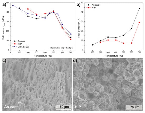
Figure 5.
(a) Tensile 0.2% yield stress and (b) total elongation of as-cast and HIPped Fe-Al-Mo-Ti-B; fracture surfaces of (c) as-cast and (d) HIPped Fe-Al-Mo-Ti-B at 600 °C. The compressive 0.2% yield stress of Fe-25.5Al-2.1Mo-0.5Ti-1.2B is added in (a) for comparison [22].
3.2. Production and Inspection of as-Manufacture Prototypes
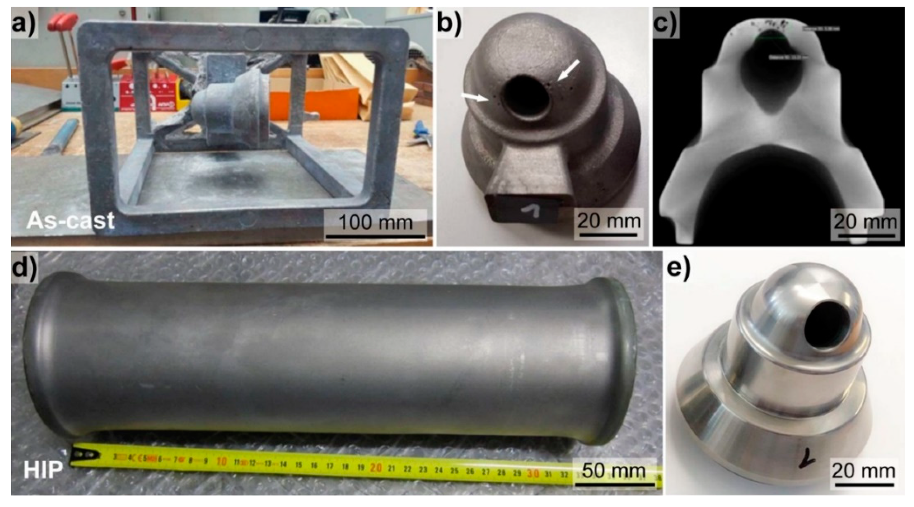
Prechamber prototypes were produced of the Fe-Al-Mo-Ti-B alloy by means of investment casting and HIP (Figure 6). Currently the prechamber in commercial use is machined from bars of a Ni-based superalloy. Investment casting offers the economically attractive opportunity to produce near net-shaped components, and hence reduce post machining times and costs. Figure 6a shows the as-cast part after removing the ceramic shell. For the prototype casting trials also the supporting structure was filled with the iron aluminide. Such a supporting structure would be omitted in serial production. The mold-filling ability of the Fe-Al-Mo-Ti-B alloy was found to be excellent, as also observed for other iron aluminide-based alloys [3]. In Figure 6b an as-cast prechamber including part of the spur is depicted. The contours of the prechamber are clearly visible and also the surface of the as-cast part appears very smooth. Some pores close to the opening (indicated by white arrows Figure 6b) are visible. CT-scans also revealed internal pores (Figure 6c). Although porosity was observed, the outcome of the castings trials is considered to be very promising, as castability is found to be very good, standard equipment could be used, and porosity should be substantially reduced with an optimized mold design.
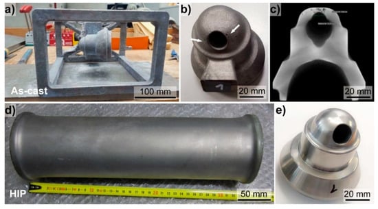
Figure 6.
Overview on manufacturing of prechamber prototypes made of the Fe-Al-Mo-Ti-B alloy via (a–c) investment casting, and (d,e) HIP. (a) Complete as-cast part after removing the ceramic shell, (b) as-cast prechamber revealing some open pores (indicated by white arrows), a smooth surfaces was apparent and the shape of the prechamber was well replicated; (c) computer tomography (CT)-scan of the as-cast prechamber; (d) stainless steel capsule after HIP, (e) final machined prechamber made from the HIP-bar.
HIP was employed as alternative processing route (Figure 6d–e). The stainless-steel capsule was homogenously deformed by the HIP-process (Figure 6d), indicating a successful consolidation of the material. In total, three prototypes of the prechamber were successfully machined from the HIP-bar (Figure 6e). Visual inspection revealed no cracks or pores. Machinability of the HIP-material was found to be comparable to that of Ni-based superalloys.
3.3. Post Analysis of Prototypes after Engine Test
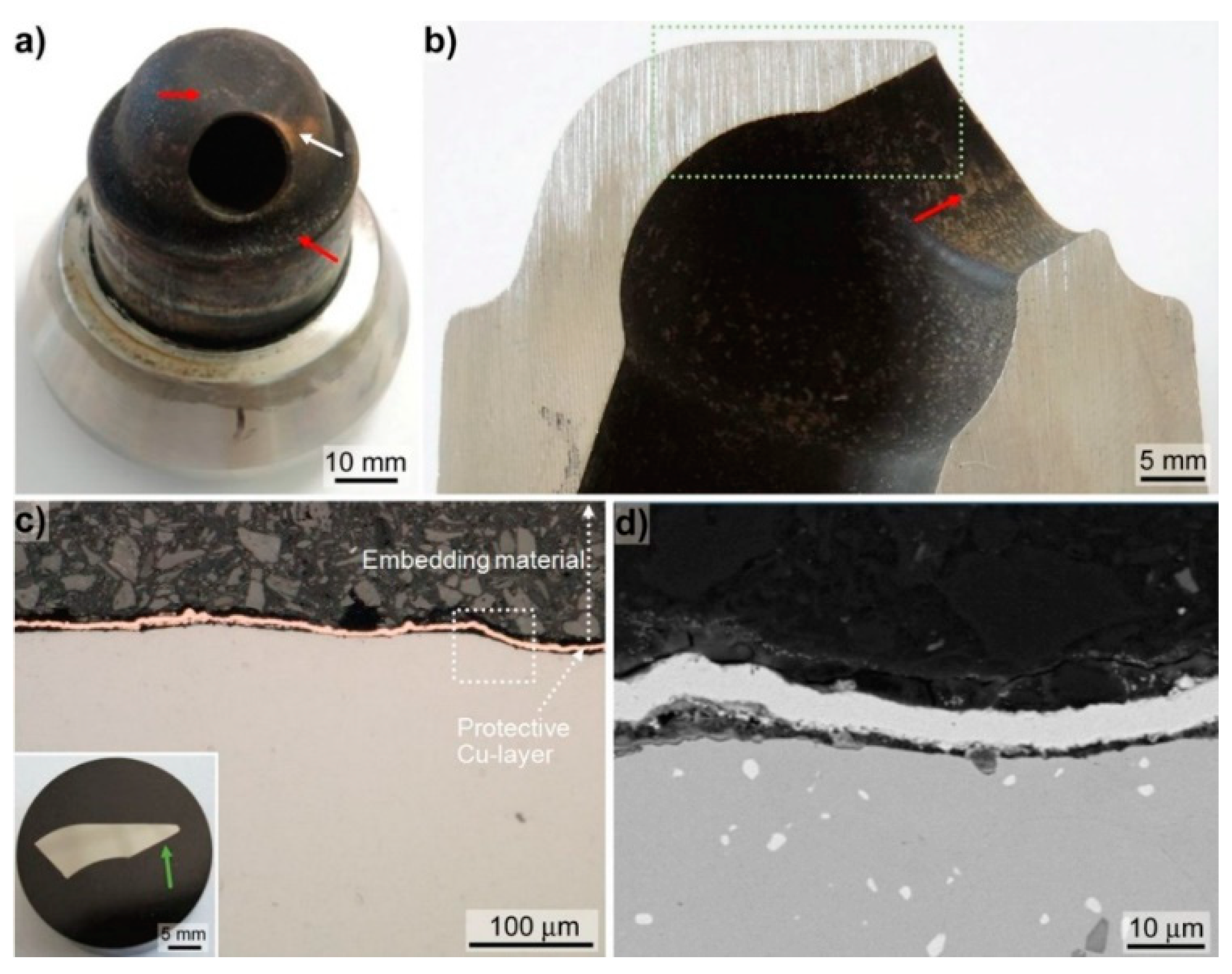
One prototype prechamber made of the Fe-Al-Mo-Ti-B alloy in the HIP condition was tested on the research engine RTX-5 located in Trieste, Italy [6]. The prototype test was running for totally 61 h: 21 running hours in gas mode and 40 running hours in diesel mode reaching maximum engine loads of 75%. Figure 7a shows the prechamber dismounted after the engine test. The lower curved part of the prechamber, which is faced towards the combustion chamber, is covered with a mostly complete black layer and some brownish appearing deposits on-top of it (indicated by red arrows in Figure 7a). In addition, some orange appearing dis-colourisation (indicated by a white arrow in Figure 7a, i.e., presumably tempering colours), is observable. In Figure 7a,b the section cut through the prechamber, showing the opening towards the combustion chamber, is displayed. The inner part of the prechamber is homogenously covered by a black layer and brownish sprinkle-like deposits (indicated by red arrow in Figure 7b are apparent). In EDS point measurements (not shown) the brownish deposits on the outside as well as on the inside of the prechamber revealed major peaks of Ca and S. Ca, in the form of CaCO3 is an additive of the cylinder lubrication oil used to prevent cold corrosion by neutralising the evolving sulphuric acid [26]. S is a constituent of the diesel fuel as well of the cylinder lubrication oil. Hence, the brownish deposits are related to residuals from the cylinder lubrication oil and the black layers are ascribed to residuals from combustion. A sample was cut from the lowest part of the sectioned prechamber part for metallographic sample preparation (position indicated by the green dotted rectangle in Figure 7b). Prior embedding the cut-off sample was coated with Cu in order to preserve the initial surface, i.e., including the deposits. However, during grinding and polishing the deposits were washed out. In the light optical (c.f. Figure 7c) as well as in the SEM images (c.f. Figure 7d) no surface defects such as cracks originating from the operation of the prechamber were observable. Furthermore, no severe signs of hot corrosive attack e.g., preferential attack along grain boundaries or of the borides were apparent (c.f. Figure 7d). Consequently, the prechamber successfully passed the engine test with no peculiarities towards degradation of the mechanical integrity or deterioration due to hot corrosive attack.

Figure 7.
Post analysis of the prechamber after the engine test; (a) image of the complete prechamber; (b) section of the prechamber showing the opening towards the combustion chamber; the green rectangle indicates the position of the metallographic section presented in the insert of (c). (c) Light optical images taken approximately at the position as indicated by the green arrow in the insert. (d) BSE-SEM images taken in BSE-mode at the position indicated by the white dotted rectangle in (c).
4. Summary and Conclusions
This study provides a unique overview ranging from microstructural analysis and determination of basic material properties of a promising Fe-Al-Mo-Ti-B iron aluminide alloy to different processing routes and manufacturing of prototype components and finally component testing.
The microstructure of the Fe-Al-Mo-Ti-B alloy in the as-cast state is characterized by a coarse-grained Fe3Al matrix (grain size > 100 µm) and eutectic seems of a complex boride of Mo2FeB2-type and Fe3Al. In the HIPped condition, equiaxed Fe3Al grains with a size of about 20 µm with evenly distributed 1–3 µm Mo2FeB2-type borides are observed. The high temperature oxidation resistance of Fe-Al-Mo-Ti-B alloys, both in the as-cast and HIPped condition, is superior compared to Nimonic 80A, which is currently applied as prechamber material. The excellent high temperature oxidation behavior is related to the formation of a dense and well adhering Al2O3 scale. The wet chemical corrosion behavior of Fe-Al-Mo-Ti-B in aqueous sulphuric acid shows a passive behavior with low critical currents. Tensile tests revealed good strength at low temperatures and a favorable ductility of the as-cast alloy due to the presence of borides at the grain boundaries. Investment casting trials showed an excellent mold-filling ability and revealed the potential of fabricating near-net shape components. Prechamber prototypes were also made from bars produced by HIP and machinability of the HIPped alloy was found to be comparable to that of Ni-based superalloys. The prototype prechamber was running for a total of 61 h on a large bore two-stroke test engine. Post analysis of the tested prechamber revealed no marked corrosive attack and no degradation of the mechanical integrity was observed.
Overall, the investigated Fe-Al-Mo-Ti-B alloys show a very interesting combination of mechanical properties, excellent high temperature oxidation resistance, passive behavior in aqueous acid containing environments and good processability and hence might meet the requirements of future demands, also with respect to costs.
Author Contributions
Conceptualization, F.M., J.P. and M.P.; methodology, J.P., U.J., and M.P.; investigation, F.M., J.P. and J.S.; resources, M.D. and M.P.; writing—original draft preparation, F.M., J.P. and M.P.; writing—review and editing F.M, J.P., J.S., U.J., M.D. and M.P.; visualization, F.M. and J.P.; project administration, F.M. and M.D. funding acquisition M.D.
Funding
The financial support received by the European Union’s research and innovation program Horizon 2020 under grant No 634135 is gratefully acknowledged.
Acknowledgments
The authors are grateful to Vera Marx for performing oxidation experiments, Marco Grasso for installation and dismounting of the pre-chamber on the test engine, and Michael Sommer for his support on the hot isostatic pressing of the powder.
Conflicts of Interest
The authors declare no conflicts of interest.
References
- Hercules 2. Available online: http://www.hercules-2.com/ (accessed on 14 September 2018).
- Stoloff, N. Iron aluminides: Present status and future prospects. Mater. Sci. Eng. A 1998, 258, 1–14. [Google Scholar] [CrossRef]
- Palm, M. Fe-Al materials for structural applications at high temperatures: Current research at MPIE. Int. J. Mater. Res. 2009, 100, 277–287. [Google Scholar] [CrossRef]
- Morris, D.G.; Muñoz-Morris, M.A. Recent developments toward the application of iron aluminides in fossil fuel technologies. Adv. Eng. Mater. 2011, 13, 43–47. [Google Scholar] [CrossRef]
- Revised MARPOL Annex VI-Prevention of Air Pollution from Ships. Available online: http://www.imo.org/en/OurWork/Environment/PollutionPrevention/AirPollution/Pages/Air-Pollution.aspx (accessed on 14 September 2018).
- Ott, M.; Nylund, I.; Alder, R.; Hirose, T.; Umemoto, Y.; Yamada, T. The 2-stroke low-pressure dual-fuel technology: From concept to reality. In Proceedings of the 28th CIMAC World Congress on combustion Engine, Helsinki, Finland, 6–10 June 2016. [Google Scholar]
- WinGD-Environmental Benefits. Available online: https://www.wingd.com/en/technology-innovation/engine-technology/x-df-dual-fuel-design/environmental-benefits/ (accessed on 14 September 2018).
- Stein, F.; Palm, M. Re-determination of transition temperatures in the Fe-Al system by differential thermal analysis. Int. J. Mater. Res. 2007, 98, 580–588. [Google Scholar] [CrossRef]
- Pint, B.; Leibowitz, J.; DeVan, J. The effect of an oxide dispersion on the critical Al content in Fe-Al alloys. Oxid. Met. 1999, 51, 181–197. [Google Scholar] [CrossRef]
- Pöter, B.; Stein, F.; Wirth, R.; Spiegel, M. Early stages of protective oxide layer growth on binary iron aluminides. Z. Phys. Chem. 2005, 219, 1489–1503. [Google Scholar] [CrossRef]
- Marx, V.; Palm, M. Oxidation of Fe-Al Alloys (5–40 at.% Al) at 700 and 900 °C. Mater. Sci. Forum 2017, 879, 1245–1250. [Google Scholar] [CrossRef]
- Sikka, V.K.; Viswanathan, S.; McKamey, C.G. Development and Commercialization Status of Fe3Al-Based Intermetallic Alloys; Research Organization: Oak Ridge, TN, USA, 1993. [Google Scholar]
- Konrad, J.; Zaefferer, S.; Schneider, A. Investigation of nucleation mechanisms of recrystallization in warm rolled Fe3Al base alloys. Mater. Sci. Forum 2004, 467, 75–80. [Google Scholar] [CrossRef]
- Hanus, P.; Bartsch, E.; Palm, M.; Krein, R.; Bauer-Partenheimer, K.; Janschek, P. Mechanical properties of a forged Fe-25Al-2Ta steam turbine blade. Intermetallics 2010, 18, 1379–1384. [Google Scholar] [CrossRef]
- Song, B.; Dong, S.; Coddet, P.; Liao, H.; Coddet, C. Fabrication and microstructure characterization of selective laser-melted FeAl intermetallic parts. Surf. Coat. Technol. 2012, 206, 4704–4709. [Google Scholar] [CrossRef]
- Michalcová, A.; Senčekova, L.; Rolink, G.; Weisheit, A.; Pešička, J.; Stobik, M.; Palm, M. Laser additive manufacturing of iron aluminides strengthened by ordering, borides or coherent Heusler phase. Mater. Des. 2017, 116, 481–494. [Google Scholar] [CrossRef]
- Morris, D.G.; Morris, M. Strengthening at intermediate temperatures in iron aluminides. Mater. Sci. Eng. A 1997, 239, 23–38. [Google Scholar] [CrossRef]
- Morris, D.G. Possibilities for high-temperature strengthening in iron aluminides. Intermetallics 1998, 6, 753–758. [Google Scholar] [CrossRef]
- Bahadur, A. Enhancement of high temperature strength and room temperature ductility of iron aluminides by alloying. Mater. Sci. Technol. 2003, 19, 1627–1634. [Google Scholar] [CrossRef]
- Palm, M. Concepts derived from phase diagram studies for the strengthening of Fe-Al-based alloys. Intermetallics 2005, 13, 1286–1295. [Google Scholar] [CrossRef]
- Morris, D.G.; Muñoz-Morris, M. Development of creep-resistant iron aluminides. Mater. Sci. Eng. A 2007, 462, 45–52. [Google Scholar] [CrossRef]
- Li, X.; Prokopčáková, P.; Palm, M. Microstructure and mechanical properties of Fe-Al-Ti-B alloys with additions of Mo and W. Mater. Sci. Eng.: A 2014, 611, 234–241. [Google Scholar] [CrossRef]
- Wagner, C. Theoretical analysis of the diffusion processes determining the oxidation rate of alloys. J. Electrochem. Soc. 1952, 99, 369–380. [Google Scholar] [CrossRef]
- Peng, J.; Fang, X.; Qu, Z.; Wang, J. Isothermal oxidation behavior of NiAl and NiAl-(Cr,Mo) eutectic alloys. Corros. Sci. 2019, 151, 27–34. [Google Scholar] [CrossRef]
- Ray, P.K.; Akinc, M.; Kramer, M.J. Formation of multilayered scale during the oxidation of NiAl-Mo alloy. Appl. Surf. Sci. 2014, 301, 107–111. [Google Scholar] [CrossRef]
- CIMAC Working Group 8 ‘Marine Lubricants’, CIMAC Guidelie “Cold Corrosion in Marine Two Stroke Engines. Available online: https://www.cimac.com/cms/upload/Publication_Press/WG_Publications/CIMAC_WG8_Guideline_2017_Two_Stroke_Engine_Cold_Corrosion.pdf (accessed on 14 September 2018).
- Peng, J.; Moszner, F.; Rechmann, J.; Vogel, D.; Palm, M.; Rohwerder, M. Influence of Al content and pre-oxidation on the aqueous corrosion resistance of binary Fe-Al alloys in sulphuric acid. Corros. Sci. 2019, 149, 123–132. [Google Scholar] [CrossRef]
- McCafferty, E. Introduction to Corrosion Science; Springer: New York, NY, USA, 2010; ISBN 978-1-4419-0454-6. [Google Scholar]
- Kim, J.; Buchanan, R. Pitting and crevice corrosion of iron aluminides in a mild acid-chloride solution. Corrosion 1994, 50, 658–668. [Google Scholar] [CrossRef]
- Agarwal, A.; Akhtar, M.; Balasubramaniam, R. Effect of alloying on aqueous corrosion and mechanical behaviour of iron aluminide Fe3Al. J. Mater. Sci. 1996, 31, 5207–5213. [Google Scholar] [CrossRef]
- Mao, Q.; Yang, Q.; Xiong, W.; Li, S.; Zhang, M.; Ruan, L. Corrosion behavior of Ni3Al-bonded TiC-based cermets in H2SO4 and NaOH solutions. Ceram. Int. 2018, 44, 13303–13312. [Google Scholar] [CrossRef]
- Caillard, D. Yield-stress anomalies and high-temperature mechanical properties of intermetallics and disordered alloys. Mater. Sci. Eng.: A 2001, 319–321, 74–83. [Google Scholar] [CrossRef]
- Hasemann, G.; Schneibel, J.H.; George, E.P. Dependence of the yield stress of Fe3Al on heat treatment. Intermetallics 2012, 21, 56–61. [Google Scholar] [CrossRef]


© 2019 by the authors. Licensee MDPI, Basel, Switzerland. This article is an open access article distributed under the terms and conditions of the Creative Commons Attribution (CC BY) license (http://creativecommons.org/licenses/by/4.0/).