Abstract
The present article analyses the influence of preheating and a postweld heat treatment in the microstructure, mechanical properties and wear behaviour of a joint of nodular graphite cast iron when using the tungsten inert gas (TIG) welding process with perlitic grey cast iron rods as filler material. Data obtained from the tests and the microstructural study of the samples show that the absence of a postweld heat treatment and of preheating leads to the apparition of hard structures and a notable reduction in elongation. Preheating or annealing the weld avoid the presence of these hard structures and increase the ductile behaviour of the joint although at the cost of a further loss of mechanical strength. Wear rate was found to be higher at the weld bead than at the base metal, even when the hardness of both areas is the same.
1. Introduction
Cast irons are alloys of iron, carbon and silicon that favours the formation of graphite, whose carbon content, due to the fact that a high percentage of carbon can induce brittleness, is maintained below 4%. Their classification depends on its metallographic structure, according to the percentages of carbon and other alloying elements. Although these materials do not have the mechanical properties of steels, they are used in numerous applications such as: hydraulic valves, transmissions, gears, nuts, shafts, hydraulic components, pistons, guides or engine liners [1].
Grey cast irons have low mechanical characteristics due to the presence of graphite flakes, which act as discontinuities in the matrix, giving rise to the presence of stress concentrators. Because of the good castabilityand low price of grey cast irons, they are used extensively for ornamental objects, manhole covers, heat exchangers or bandstands
In contrast, in nodular cast irons the addition of Magnesium, Magnesium-ferrosilicon or Magnesium-Nickel favours the formation of graphite nodules instead of graphite flakes, improving the mechanical strength, toughness and ductility of the cast iron without losing the ease of the moulding ofgrey cast irons [2]. This type of cast iron is employed in pipes and fittings, automotive applications, agricultural machinery and general industrial equipment.
Malleable cast irons castings are another type of cast irons, although with less applications than grey or nodular cast irons. They are basically iron-carbon alloys with a high carbon content that has a graphite-free structure (white cast irons) in their as-cast condition but are afterwards subjected to a thermal treatment that leads to the dissolution of cementite and the apparition of graphite.
There are two types of malleable castings: White heart malleable cast iron (European), which are decarburized cast irons with graphite in the form of irregular nodules and black heart cast iron (American) whose final structure after the heat treatment of the white cast iron is formed mainly of pearlite or perlite and irregular nodules of graphite.
Welding cast iron pieces is not a common practice and usually it is limited to repair operations and not joining due to the apparition of martensite or fragile carbides during the cooling phase of the joint. Nevertheless and although joining of cast iron pieces remains a difficult issue, it is possible if some precautions are taken.
The weld is usually performed using Ni, Ni-Cu or Ni-Fe electrodes for the best performance, although if a lower cost is mandatory, low-carbon manganese steels for non-machinable joints or cast iron rods can be used.
The mechanical properties of a weld joint depend on the welding process and the filler material but also on the preheating temperature and on the duration and temperature of the postweld heat treatment [3]. These two heat treatments are optional but necessary for high carbon content alloys such as cast irons in order to reduce the cooling rate and avoid or reduce the apparition of hard structures at the heat affected zone (HAZ).
The aim of this study has been to evaluate the influence of preheating and subjecting the weld to a postweld heat treatment on the mechanical characteristics of a TIG weld of two nodular iron plates when a perlitic grey cast iron rod is used as filler material. The use of grey cast iron as filler material is justified by its lower cost when compared to Ni electrodes and the possibility of obtaining a machinable joint. Furthermore, the presence of hard microstructures is almost unavoidable in cast iron joints, even after an annealing when high cost Ni electrodes have been used [3,4,5] but it could be less difficult to get rid of them with a thermal treatment if cast iron rods are used.
The wear behaviour of the joint was also evaluated due to the fact that many tools fabricated using nodular cast iron are affected by wear (ploughs, gears, drums, automotive components, etc.) [6,7,8] and the changes in hardness and microstructure caused by the welding process will affect its wear resistance mainly due to the presence of hard structures of martensite and carbides.
2. Materials and Methods
2.1. Materials
A nodular cast iron was used as base material. Its chemical composition and mechanical characteristics are shown in Table 1 and the mechanical properties of this cast iron can be seen in Table 2.

Table 1.
Composition of the base and the filler materials.
Table 2.
Mechanical properties of the base and the filler materials.
As filler meal, an ER perlitic grey cast iron rod with a diameter of 4 mm whose composition and properties can be seen in Table 1 and Table 2 was selected. This material has lower properties than the base material due to the effect of the graphite flakes and does not seem to be the best option to weld nodular cast irons. Nevertheless, it is important to know the microstructure and properties of the joint and how the best properties can be obtained in case no other suitable material is available.
The microstructure of both materials can be seen in Figure 1. The nodular cast iron has a ferritic-perlitic matrix and the grey cast iron has a perlitic matrix with flake graphite type V (star-like).
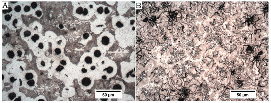
Figure 1.
Microstructure of cast irons (A) Nodular cast iron (B) Perlitic grey cast iron.
2.2. Welding Processes
The plates were obtained by sand mould casting six plates of dimensions 170 mm ×50 mm × 6 mm. These plates where subsequently milled to dimensions 170 mm × 50 mm × 5 mm. The edges were prepared for welding with a single 30° bevel by means of a refrigerated cut with an adjustable band saw.
The joint was carried out using the TIG process, one of the techniques currently most used for elements whose thickness is less than 8 mm and for the root pass in parts of greater thicknesses in order to avoid a lack of penetration. The use of this technique is advisable in the welding of castings of spheroidal graphite of certain thicknesses that require previous preparation [9]. The welding parameters were: DC current between 120 and 130 A at 14 V, direct polarity and an Argon gas flow rate of 12 L/min. The net heat input was 455 J/mm.
The welds were done in two passes using a Fronius Trans TIG 1700 machine (a first root pass and a second filling pass, Fronius international, Wels, Austria), both with a circular movement of advance in the horizontal plane and from right to left. The angle of inclination of the tungsten electrode was between 70° and 80° in the advance direction while the angle of the filler rod was about 20° on the horizontal plane. A separation of 2 mm was maintained between both plates and the bevels were cleaned and deoxidized. This helps avoid undercuts and inclusions and ensure a good penetration.
Due to the difficulty in the process of welding cast irons and in order to avoid cracking due to the stresses generated in the cooling, the weld passes were made in lengths of approximately 30 mm that were peened while hot with a small peen hammer to relieve residual stresses. Another drawback of cast iron welding is the lack of fluidity of the molten metal, what causes porosity and complicates obtaining a good penetration.
As cast irons have a great tendency to produce fragile structures at the HAZ during the cooling of the joint, once finished, the weld was covered with a ceramic blanket to avoid rapid cooling [10].
The welded samples were divided into three groups depending on the exact welding process:
- -
- Group 1: Without preheating or postweld heat treatment.
- -
- Group 2: The coupon was annealed at 900 °C for 1 h and slowly cooled down inside the furnace.
- -
- Group 3: The plates where preheated up to 450 °C before welding. The temperature was maintained around this value between passes.
2.3. Tests
Different test samples were obtained from each coupon:
- -
- Five test pieces of 20 mm width and 100 mm length for tensile tests
- -
- One sample for metallographic examination of the weld and microhardness measurement
- -
- One sample for pin-on-disc tests.
The tensile tests were performed in an Instron universal testing machine (Instron, Norwood, MA, USA) model 4204 at a speed of 5 mm/min according to the UNE-EN 10002-1 standard for tensile tests at room temperature. SEM images were taken for each one of the surfaces of the breakthroughs at 3 kV in order to obtain information about the fracture.
For the micrographic examination, the specimens were grinded up to number 1000 sandpaper and subsequently polished using 3 and 1 μm diamond paste. Finally they were etched with Nital 3.
Microhardness was measured according to the UNE-EN 876 standard using an Innovatest 400Amicrohardness tester (Innovatest Europe BV, Maastricht, The Netherlands) with a load of 300 g and a dwell time of 10 s at the HAZ, the fusion line and the weld bead. The hardness corresponds to the mean value of 5 indentations.
To compare the wear behaviour of the weld bed with the wear behaviour of the HAZ and the base metal a pin-on-disk test was carried out for each one of the groups using a normal load of 10 N and a radius of 5 mm. A F-5210 steel ball of 5 mm diameter was used in the tests, that covered 50 m of distance at a rotational speed of 60 rpm. The circular path of the ball covered both the weld bead and the base metal. The surface was grinded up to 500 grit sandpaper before the tests.
After the pin-on-disc tests the response of the material was evaluated measuring the profile of the wear track using a Marh M2 profilometer (Microtest, Madrid, Spain) [11,12].
3. Results
Table 3 show the mean value of the results obtained from the tensile tests and Figure 2 shows the microhardness profile evolution from the base metal to the weld bead. Each hardness value corresponds to the mean value of 5 measurements.
Table 3.
Mechanical characteristics of spheroidal graphite cast iron welding (A is the Elongation).
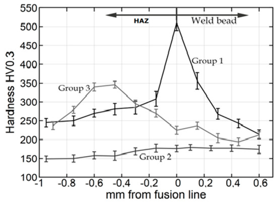
Figure 2.
MicroVickers hardness evolution from the base metal to the weld bead for group 1, group 2 (preheated at 450 °C) and group 3 samples (annealed at 900 °C).
Figure 3 shows the wear tracks on the surface of the coupons after the pin-on-disc tests. The profile of the tracks at the weld bead and at the base metal can be seen in Figure 4.
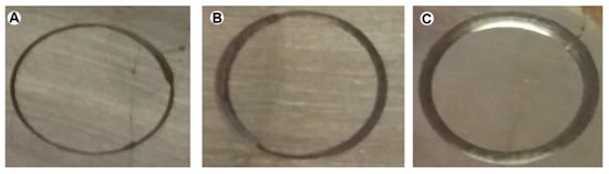
Figure 3.
Wear tracks for (A) group 1, (B) group 2 (preheated at 450 °C) and (C) group 3 samples (annealed at 900 °C).
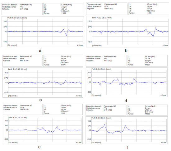
Figure 4.
Wear graphs: (a,b) Without thermic treatment. (c,d) With preheating 450 °C. (e,f) Annealed at 900 °C.
4. Analysis of Results
Figure 5 shows the microstructure of the HAZ, the weld bead and the interface between them for group 1 coupons. The microstructure at the weld bead (Figure 5a) is that of a grey cast iron with compacted graphite [13]. The HAZ (Figure 5b) show large graphite nodules surrounded by ferrite in a perlitic matrix where some small precipitates of iron carbide are present. The most important changes have taken place next to the fusion line (Figure 5c), where hard ledeburite coexists along graphite nodules. The presence of such a hard microconstituent raise the hardness of the zone to 510 HV, much higher than the one measured at the weld bead or the HAZ [14], where hardness decreases rapidly by one-half. A notable hardness increment with respect to the base or the filler metal was found around the fusion line.
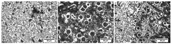
Figure 5.
Micrograph of the joint without preheating nor post weld heat treatment. (a) Weld bead. (b) HAZ. (c) Interface.
This change in the microstructure leads to a more brittle behaviour of the joint in comparison with the base metal, even though the mechanical properties of the joint are higher than those of the filler metal, perhaps due to the effect of the part of the base metal that melts and mixes with the filler metal (dilution) to form the weld bead, changing its composition. Elongation, that goes from 14% to 9%, is the most affected parameter.
In the tensile tests the breakage took place at the weld bead (Figure 6A) and the crack faces show the intergranular aspect that can be seen in the scanning electron microscopy (SEM) image shown in Figure 7.
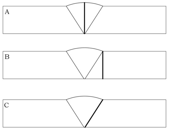
Figure 6.
Location of the break in the tensile tests. (A) At the weld bead in group 1, (B) at the HAZ in group 2 and (C) at the fusion line in group 3.
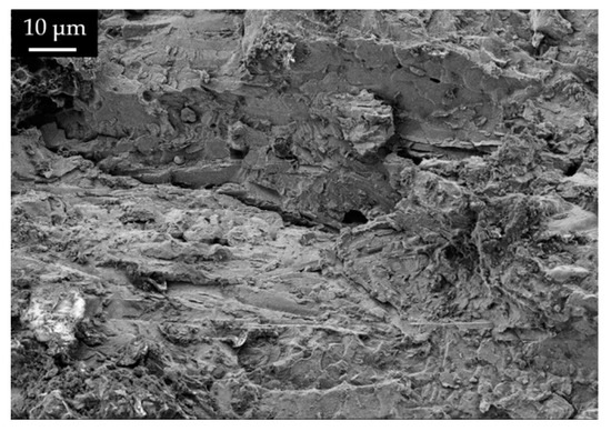
Figure 7.
SEM image of the broken surface for group 1 samples.
Figure 8 corresponds to the different microstructures found at the joint after an annealing at 900 °C for 1 h and subsequent slow cooling in the furnace. A notable difference is observed with respect to the previously described microstructure, in which no treatment had been applied.
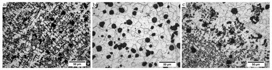
Figure 8.
Micrograph of the joint after an annealing at 900 °C. (a) Weld bead. (b) HAZ. (c) Interface.
The most important change (Figure 8c) is the absence of ledeburite or any other rest of fragile microstructures next to the fusion line. In its place, a fast transition between the weld bead and the base material is found. The effect of the heat treatment leads at the HAZ (Figure 8b) [15] to the disappearance of the perlitic-ferritic matrix, that is replaced by a fully ferritic matrix with a hardness below 174 HV. Similar hardness values were measured at the weld bead (Figure 8a) [16]. The main difference between the microstructure of the weld bead and the HAZ is the graphite shape, compacted or vermicular at the weld bead and fully nodular at the HAZ [17].
Breakage took place at the HAZ as shown in Figure 6B. The aspect of the broken surface can be seen in Figure 9. In this case, the aspect of the fracture corresponds to a more ductile behaviour at a ferritic matrix.
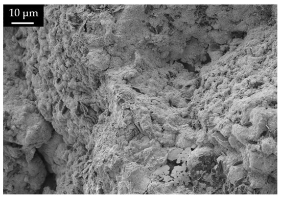
Figure 9.
SEM image of the broken surface for group 2 samples.
The softening of the microstructure caused by the annealing improves elongation, that now reaches a value of 12% but is also accompanied by a drop in the values of yield and ultimate strength. The new values of these variables are now very similar to the ones of the filler metal but with a higher elongation. This still represents a loss of properties for the welded plates in every aspect.
The microstructure (Figure 10) of the group 3 coupons, welded after preheating the plates at 450 °C could be described as a mixture between the two previously described. No hard structures of cementite can be observed next to the fusion line (Figure 10c), an effect of the slower cooling rate caused by having heatedthe plates at 450 °C before welding. At the HAZ (Figure 10b) graphite nodules surrounded by ferrite are observed in a perlitic matrix. The higher harness values are found at the HAZ, around 0.5 mm from the fusion line. At this zone, values near 350 HV were measured, while at the fusion line hardness was only 225 HV. This location of the most hardened material is due to the coincidental combination of maximum reached temperature and cooling rate of each point of the joint. At the weld bead hardness in maintained always below 240 HV.
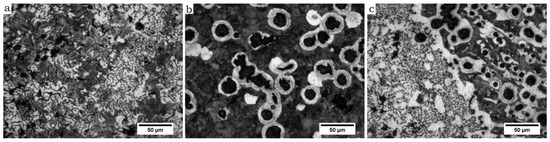
Figure 10.
Micrograph of the joint preheated at 450 °C. (a) Weld bead. (b) HAZ. (c) Interface.
In these coupons the hardness distribution is inverted in relation to the original materials, where the higher hardness corresponds to the filler [18]. The microstructure at the weld bead show vermicular graphite in a ferritic-perlitic matrix, although some irregular graphite nodules are visible.
The achieved mechanical strength of this joints is a bit higher than the corresponding to group 2, although with a lower value of elongation.
The surface showed an aspect between ductile and brittle. The crack propagated in an intergranular way along the fusion line as indicated in Figure 6C. A SEM image of the surface is shown in Figure 11.
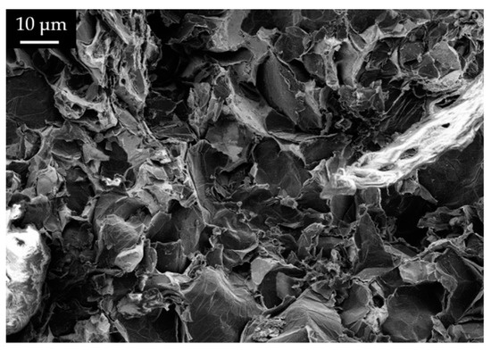
Figure 11.
SEM image of the broken surface for group 3 samples.
Regarding the wear resistance of the joint, it was evaluated measuring the width and depth of the wear track both at the weld bead and at the HAZ (base material). The wear behaviour of the material near the fusion line, where ledeburite was found for group 1 coupons, was not evaluated due to the small size of this zone.
For the group 1 coupons the wear track had a width of 0.30 mm and an average depth of 2.5 microns at the HAZ and of 0.35 mm and 3 microns at the weld bead (Figure 4a,b) [19].
The width of the wear track at the HAZ for the group 2 coupons (with preheating) was 0.4 mm and the depth 4 microns. These values were 0.65 mm and 5 microns at the weld bead (Figure 4c,d).
Finally, in group 3 (annealed coupons) the wear track profile had a dimensions of 0.4 mm width and 4 microns depth at the base material and 0.9 mm width and 7 microns depth at the weld bead (Figure 4e,f).
Lower hardness values lead to higher wear and a bigger track as the resistance to abrasive wear diminishes but hardness is not the only influencing variable, as can be seen in the fact that wear is always higher at the weld bead than at the base metal even when both zones have the same hardness [20,21]. This indicates that the microstructure and the shape adopted by graphite plays a crucial role, being the vermicular graphite the most susceptible to wear.
5. Conclusions
In summary, the use of grey cast iron as filler material reduces the hardness of the fusion line with respect to the use of Ni alloys, case in which values of 700 HV are obtained [3,17,18], facilitates the dissolution of these hard microstructures with an annealing and even avoids its apparition when preheating at 450 °C, what does not happen with Ni alloys and mechanical characteristics similar to those obtained with Ni-based electrodes are reached [5,17,18]. Nevertheless, the use of grey cast iron, with lower mechanical characteristics than the base metal, limits the properties to those of the filler alloy.
The maximum loss of elongation corresponds to the weld carried out without preheating or postweld heat treatment, although it has the higher strength. These welds have the hardest microstructure with presence of ledeburite at the fusion line.
A preheating at 450 °C is enough to avoid very hard structures at the fusion line and a certain recovery of ductility, avoiding the high cost of an annealing.
The most important ductility recovery happens when the joint is subjected to an annealing treatment at 900 °C. In this case elongation reaches 12%, although the values of ultimate and yield strength reaches their minimum. With this treatment hardness also reaches its lower values in all the weld zones, below the hardness of the base material, that now has a ferritic matrix due to the ferritizing effect of the annealing.
The changes that take place in the microstructure lead to a different breakage location for each test group. At the weld bead for group 1 samples, at the HAZ for group 2 samples, when the weld was annealed and at the fusion line when the plates were preheated.
As regards the wear behaviour of the joint, the most hard structures are, as expected, also the lest affected by wear. This means the joints carried out without preheating and not annealed are the most resistant to wear and the less resistant the annealed ones, with wear track widths of 0.35 and 0.9 mm each one at the weld bead.
Another important result is that the wear track width is always wider and deeper at the weld bead than at the HAZ even when the hardness of both zones are very similar. This means the vermicular shape of the graphite at the weld bead makes this material more susceptible to wear than the graphite nodules of the base material.
Author Contributions
In this investigation, F.-J.C.-C. and M.P.-G. conceived and designed the experiments; F.-J.C.-C., F.S.-V. and V.D.-Q. performed the experiments; F.-J.C.-C., F.S.-V. and M.P.-G. analysed the data; V.D.-Q. contributed materials/analysis tools; F.-J.C.-C. and M.P.-G.wrote the paper.
Funding
This research received no external funding.
Acknowledgments
We would like to give thanks to materials technology institute (ITM) of Universitat Politècnica de València, Spain, for supporting this research.
Conflicts of Interest
The authors declare no conflict of interest.
References
- Lacaze, J.; Sertucha, J.; Larrañaga, P.; Suárez, R. Statistical study to determine the effect of carbon, silicon, nickel and other alloying elements on the mechanical properties of as-cast ferritic ductile irons. Rev. Metal. 2016, 52. [Google Scholar] [CrossRef]
- Suárez Sanabria, A.; Fernández Carrasquilla, J. Microestructura y propiedades mecánicas de una fundición esferoidal ferrítica en bruto de colada para su uso en piezas de grandes dimensiones. Rev. Metal. 2006, 42, 18–31. [Google Scholar]
- Pouranvari, M. On the weldability of grey cast iron using nickel based filler metal. Mater. Des. 2010, 31, 3253–3258. [Google Scholar] [CrossRef]
- Gouveia, R.M.; Silva, F.J.; Paiva, O.C.; de Fátima Andrade, M.; Pereira, L.A.; Moselli, P.C.; Papis, K.J. Comparing the Structure and Mechanical Properties of Welds on Ductile Cast Iron (700 MPa) under Different Heat Treatment Conditions. Metals 2018, 8, 72. [Google Scholar] [CrossRef]
- Pascual-Guillamón, M.; Cárcel-Carrasco, J.; Pérez-Puig, M.Á.; Salas-Vicente, F. Influence of an ERNiCrMo-3 root pass on the properties of cast iron weld joints. Rev. Metal. 2018, 54, e122. [Google Scholar] [CrossRef]
- Milosan, I. The Manufacturing of a Special Wear-resistant Cast Iron Used in Automotive Industry. Procedia Soc. Behav. Sci. 2014, 109, 610–613. [Google Scholar] [CrossRef]
- Oksanen, V.; Valtonen, K.; Andersson, P.; Vaajoki, A.; Laukkanen, A.; Holmberg, K.; Kuokkala, V.T. Comparison of laboratory rolling–sliding wear tests with in-service wear of nodular cast iron rollers against wire ropes. Wear 2015, 340–341, 73–81. [Google Scholar] [CrossRef]
- Medyńskia, D.; Janus, A. Effect of heat treatment parameters on abrasive wear and corrosion resistance of austenitic nodular cast iron Ni–Mn–Cu. Arch. Civ. Mech. Eng. 2018, 18, 515–521. [Google Scholar] [CrossRef]
- Cárcel-Carrasco, F.J.; Pérez-Puig, M.A.; Pascual-Guillamón, M.; Pascual-Martínez, R. An Analysis of the Weldability of Ductile Cast Iron Using Inconel 625 for the Root Weld and Electrodes Coated in 97.6% Nickel for the Filler Welds. Metals 2016, 6, 283. [Google Scholar] [CrossRef]
- Abboud, J.H. Microstructure and erosion characteristic of nodular cast iron surface modified by tungsten inert gas. Mater. Des. 2012, 35, 677–684. [Google Scholar] [CrossRef]
- Sellamuthu, P.; Samuel, D.G.; Dinakaran, D.; Premkumar, V.P.; Li, Z.; Seetharaman, S. Austempered Ductile Iron (ADI): Influence of Austempering Temperature on Microstructure, Mechanical and Wear Properties and Energy Consumption. Metals 2018, 8, 53. [Google Scholar] [CrossRef]
- Islam, M.A.; Haseeb, A.S.M.A.; Kurny, A.S.W. Study of wear of as-cast and heat-treated spheroidal graphite cast iron under dry sliding conditions. Wear 1995, 188, 61–65. [Google Scholar] [CrossRef]
- El-Banna, E.M. Effect of preheat on welding of ductile cast iron. Mater. Lett. 1999, 41, 20–26. [Google Scholar] [CrossRef]
- Askari-Paykani, M.; Shayan, M.; Shamanian, M. Weldability of ferritic ductile cast iron using full factorial design of experiment. Int. J. Iron Steel Res. 2014, 21, 252–263. [Google Scholar] [CrossRef]
- Hütter, G.; Zybell, L.; Kuna, M. Micromechanical modeling of crack propagation in nodular cast iron with competing ductile and cleavage failure. Eng. Fract. Mech. 2015, 147, 388–397. [Google Scholar] [CrossRef]
- Zhang, Y.Y.; Pang, J.C.; Shen, R.L.; Qiu, Y.; Li, S.X.; Zhang, Z.F. Investigation on tensile deformation behavior of compacted graphite iron based on cohesive damage model. Mater. Sci. Eng. 2018, 713, 260–268. [Google Scholar] [CrossRef]
- Pascual, M.; Cembrero, J.; Salas, F.; Martínez, M.P. Analysis of the weldability of ductile iron. Mater. Lett. 2008, 62, 1359–1362. [Google Scholar] [CrossRef]
- El-Banna, E.M.; Nageda, M.S.; El-Saadat, M.A. Study of restoration by welding of pearlitic ductile cast iron. Mater. Lett. 2000, 42, 311–320. [Google Scholar] [CrossRef]
- Cui, J.; Chen, L. Microstructure and abrasive wear resistance of an alloyed ductile iron subjected to deep cryogenic and austempering treatments. J. Mater. Sci. Technol. 2017, 33, 1549–1554. [Google Scholar] [CrossRef]
- Cárcel-Carrasco, J.; Pascual, M.; Pérez-Puig, M.; Segovia, F. Comparative study of TIG and SMAW root welding passes on ductile iron cast weldability. Metalurgija 2017, 56, 91–93. [Google Scholar]
- Cárcel-Carrasco, F.J.; Pascual-Guillamón, M.; Pérez-Puig, M.A. Effects of X-rays radiation on AISI 304 stainless steel weldings with AISI 316L filler material: A study of resistance and pitting corrosion behavior. Metals 2016, 6, 102. [Google Scholar] [CrossRef]


© 2019 by the authors. Licensee MDPI, Basel, Switzerland. This article is an open access article distributed under the terms and conditions of the Creative Commons Attribution (CC BY) license (http://creativecommons.org/licenses/by/4.0/).