Investigation on the Effect of Tool Pin Profiles on Mechanical and Microstructural Properties of Friction Stir Butt and Scarf Welded Aluminium Alloy 6063

 , ,
, ,  and
and 
Abstract
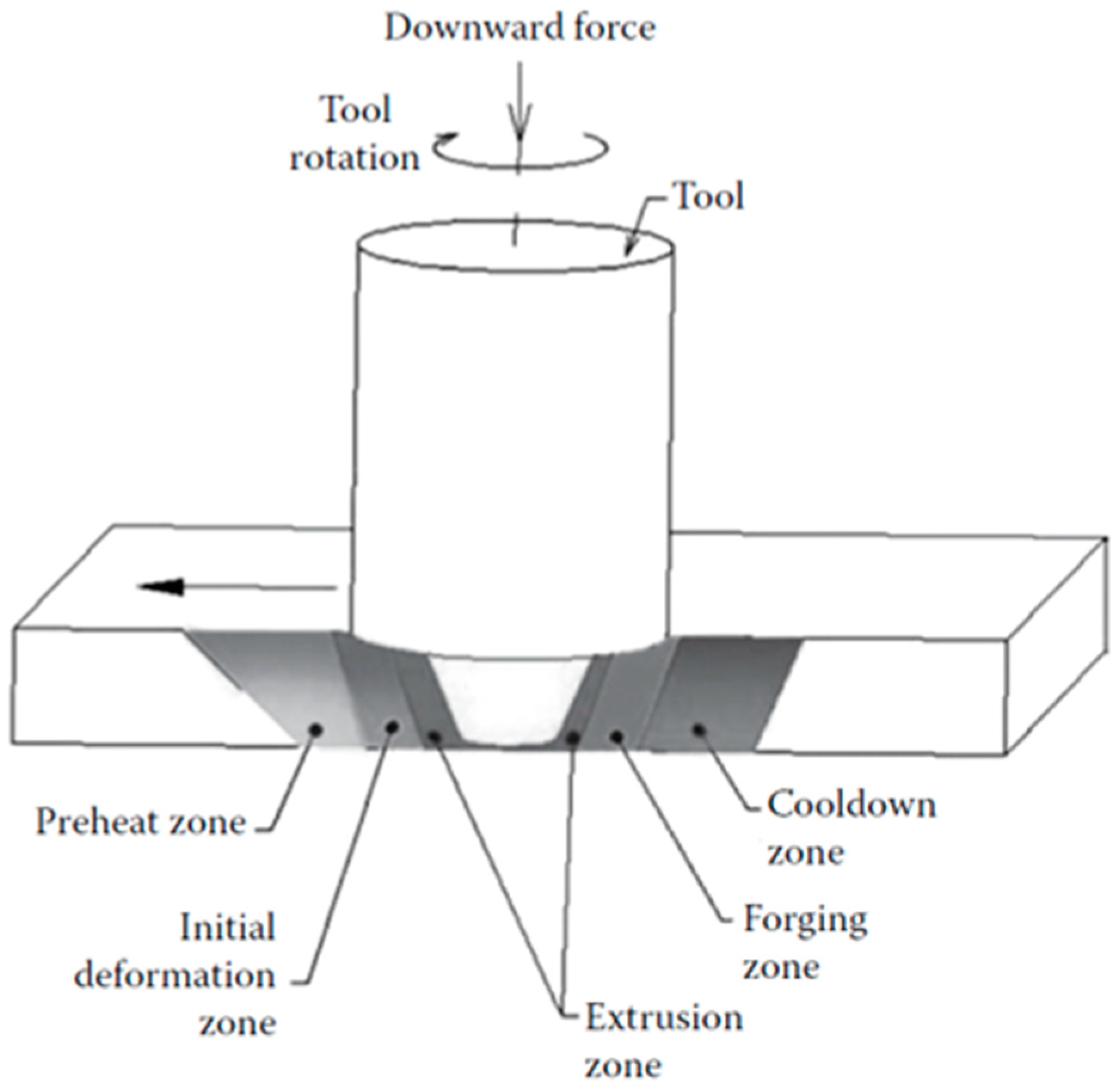
:1. Introduction
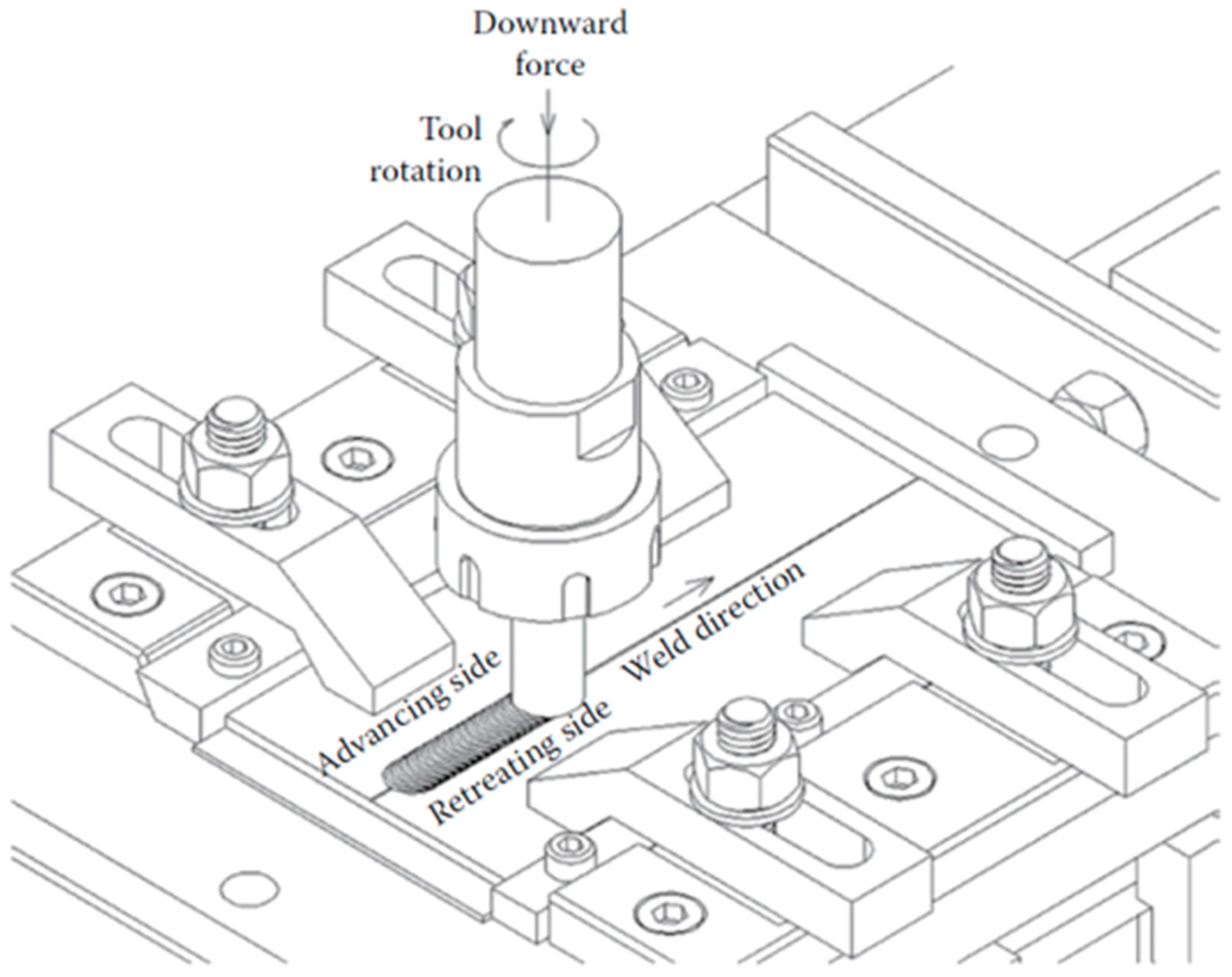
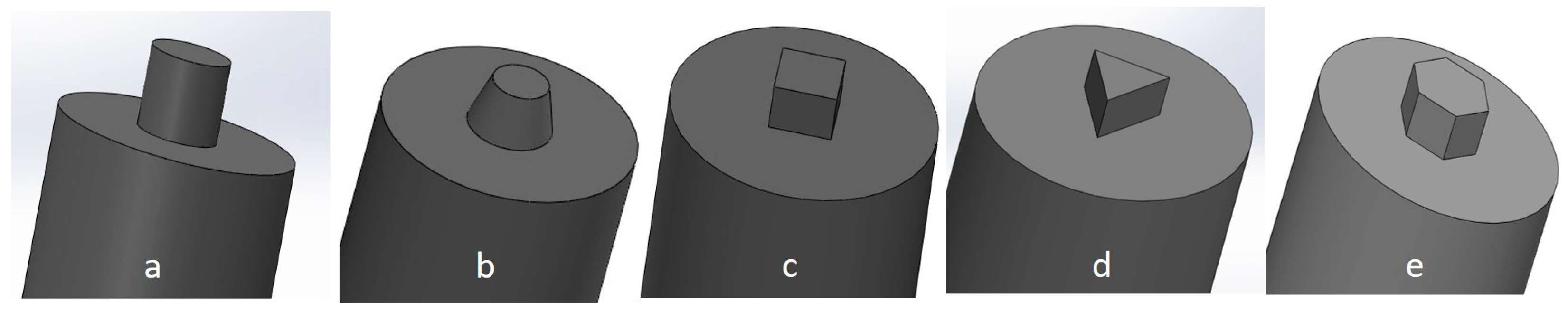
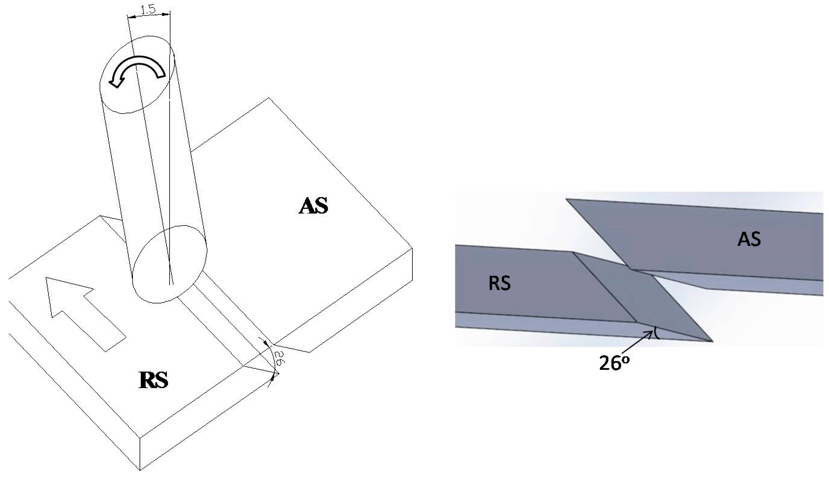
2. Experimental Method
3. Results and Discussion
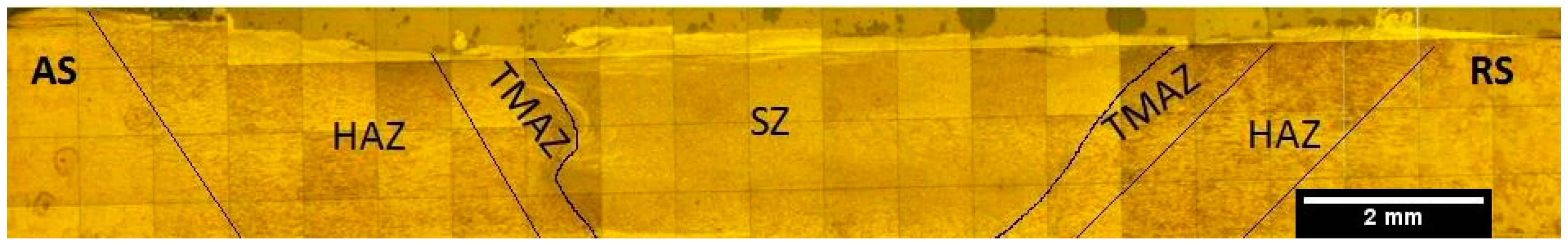
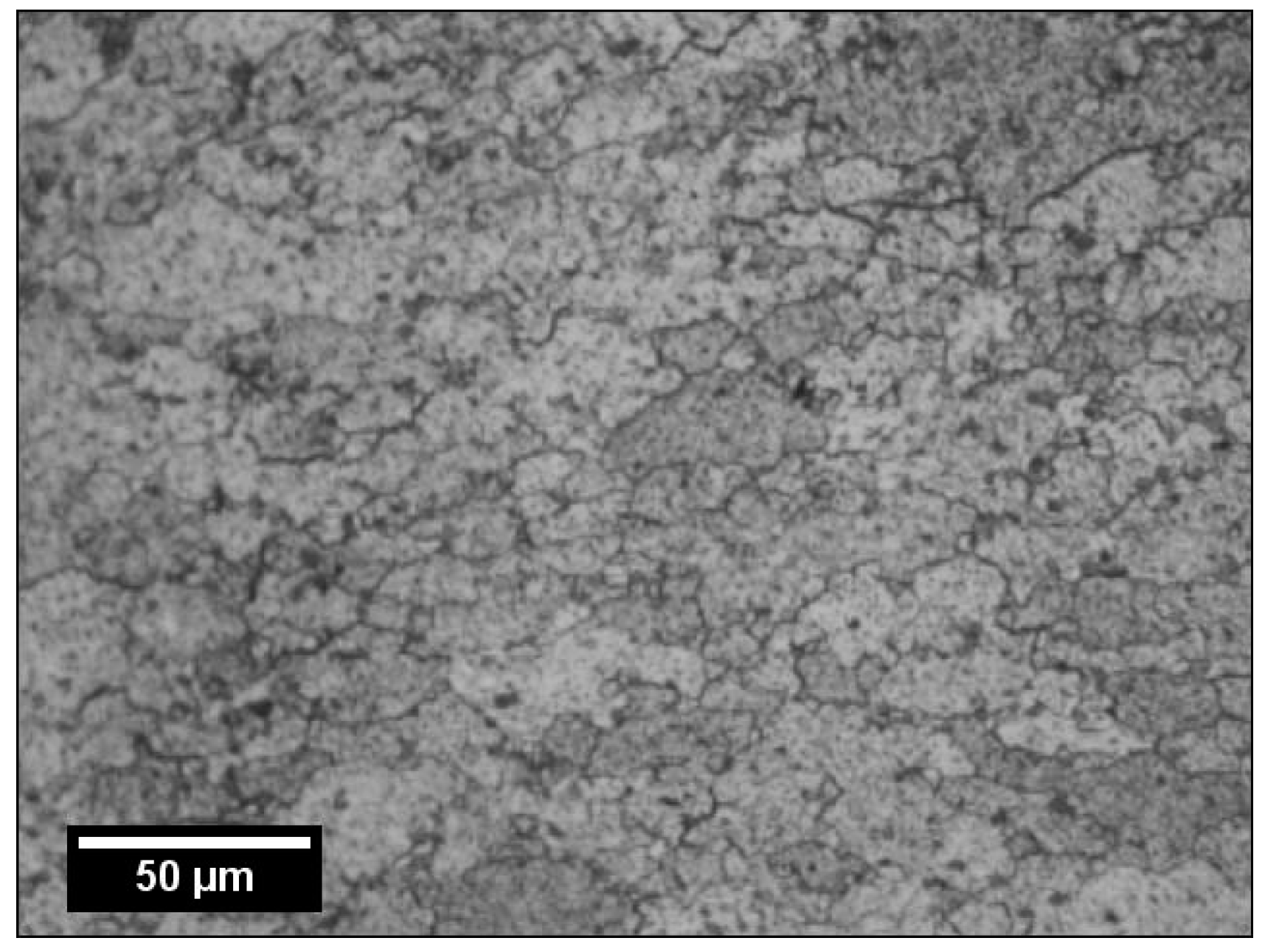
3.1. Microstructure Evolution of Butt Joint
3.2. Microstructure Evolution of Scarf Joint
3.3. Mechanical Testing
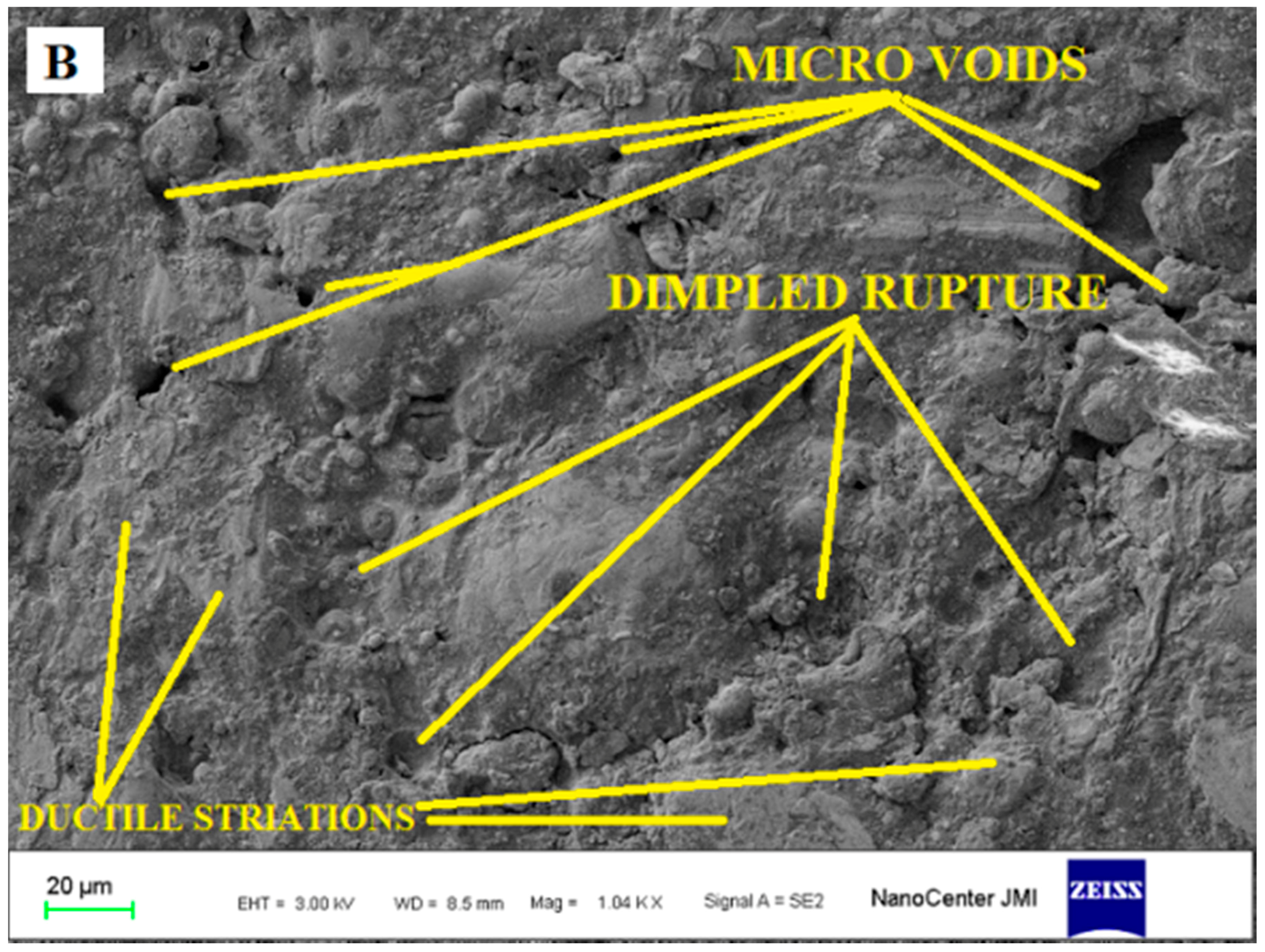
3.4. Fractography
3.5. Micro-Hardness Distribution
4. Conclusions
- FS welded butt joints fabricated with Tapered Cylindrical tools exhibited the highest tensile strength (162 MPa), whereas triangular tools showed the lowest tensile strength (115.6 MPa).
- Maximum impact strength of the FS welded butt joint is found to be 26 joules for Tapered Cylindrical tools.
- The low strength obtained in the case of scarf joints is due to relatively new joint configuration and improper features of the joints such as inclination angle, plate positioning and improper plunge.
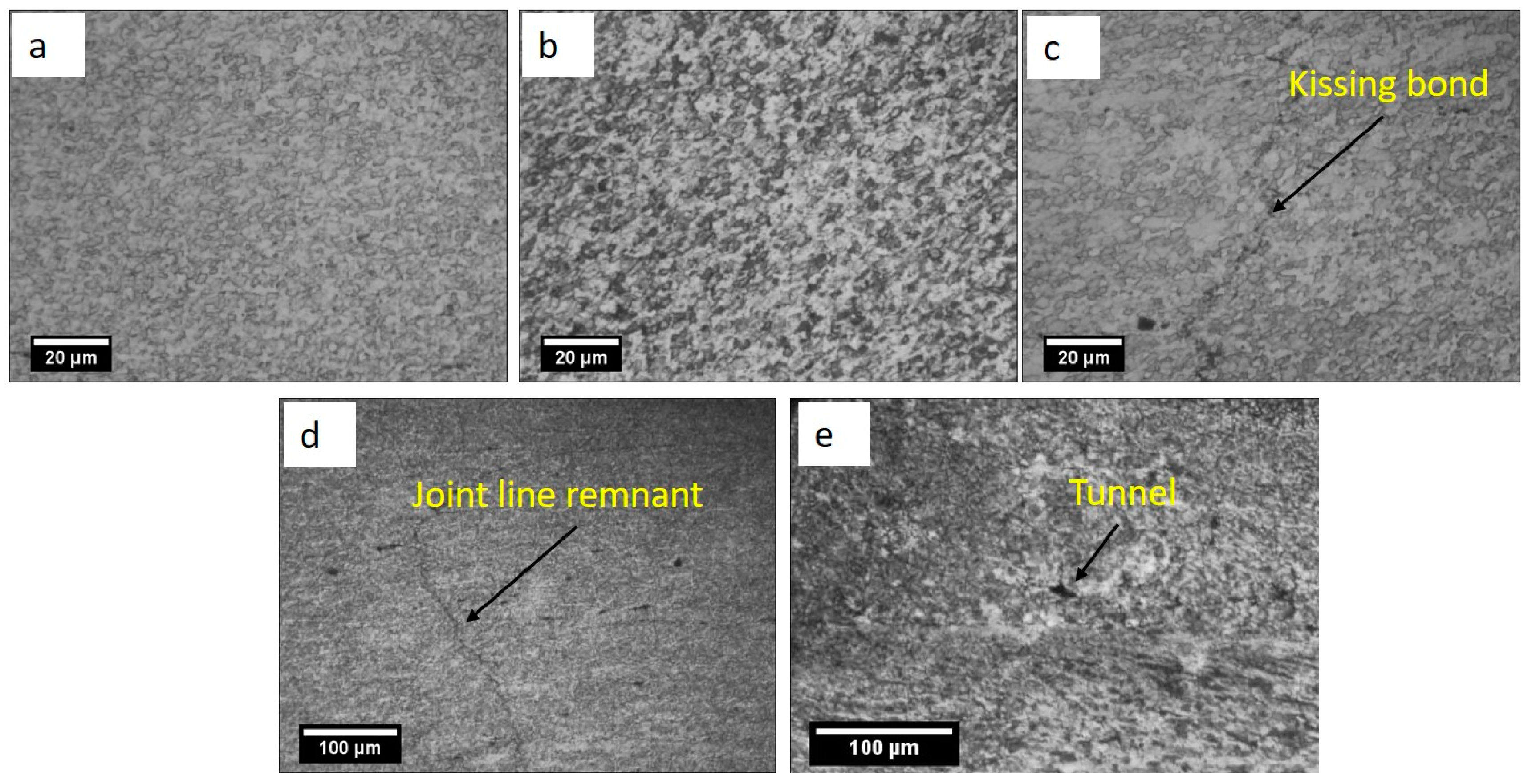
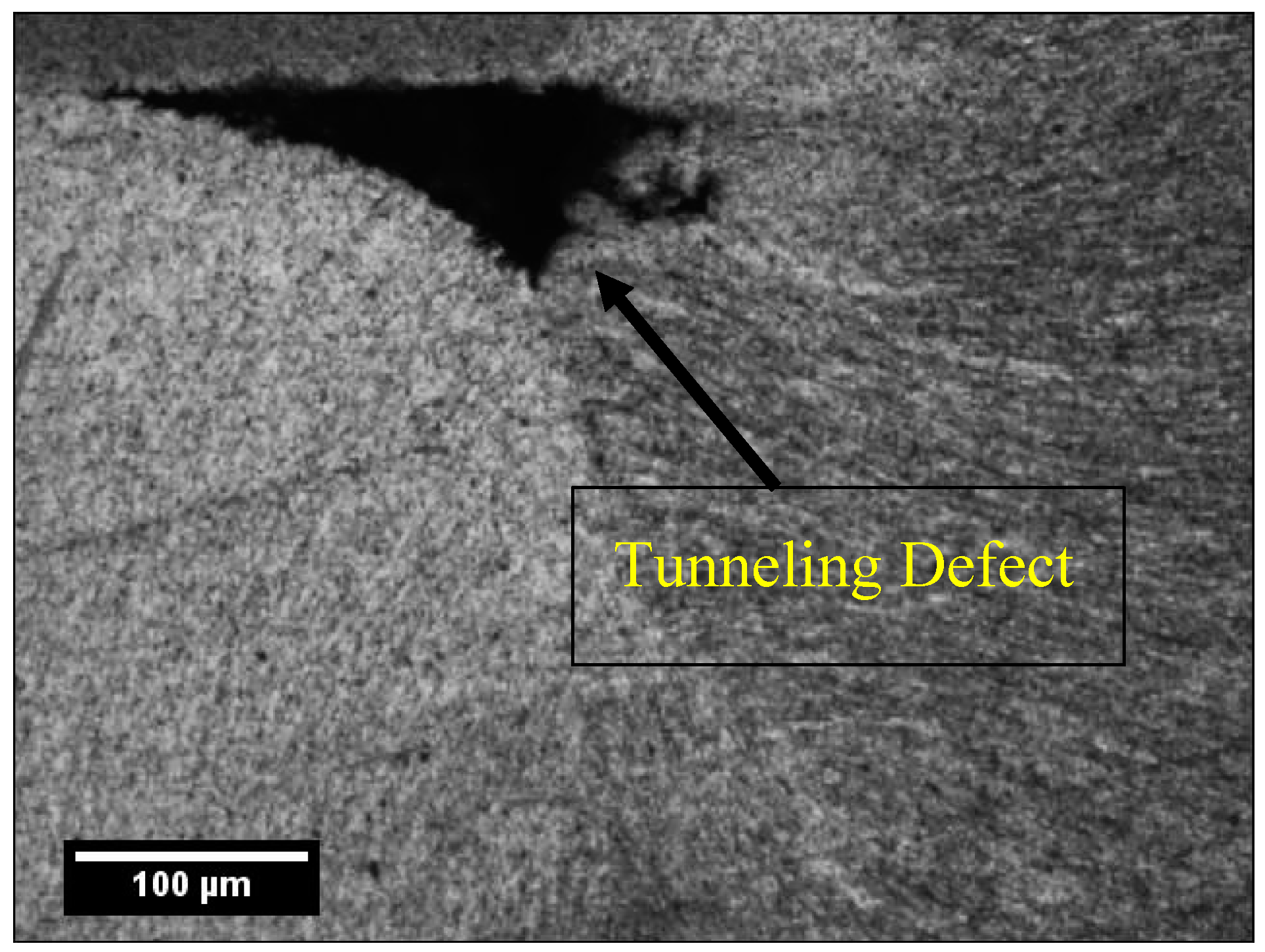
- Tunnel defects are found on the advancing side of the butt joint fabricated using triangular pin profiles due to the improper flow of material and inadequate consolidation.
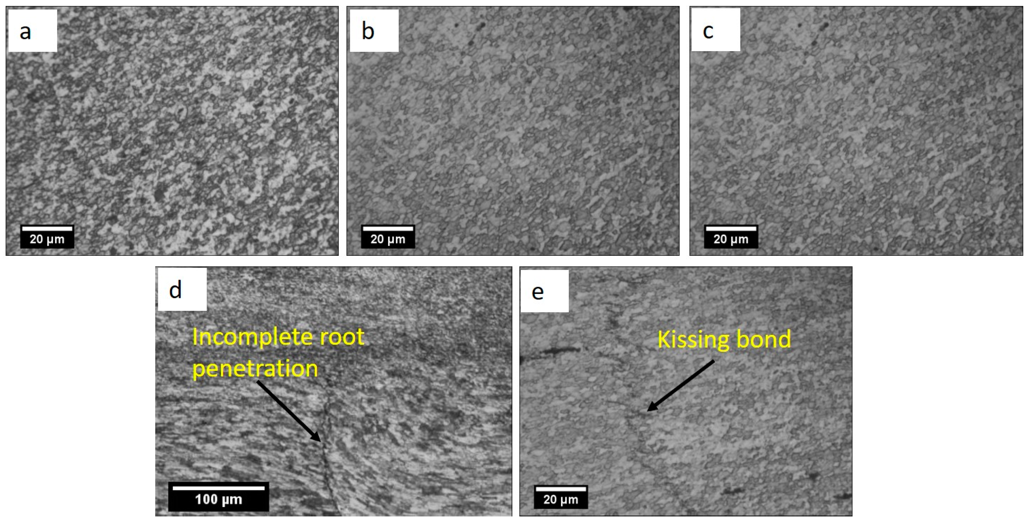
- Hooking, kissing and zigzag line defects were observed in the weld zone of scarf joint configurations due to improper combination of process parameters employed for welding.
- FSW on scarf joints has been performed on the parameter combinations, which were optimized for butt joints.
Acknowledgments
Author Contributions
Conflicts of Interest
References
- Arbegast, W.J. A flow-partitioned deformation zone model for defect formation during friction stir welding. Scr. Mater. 2008, 58, 372–376. [Google Scholar] [CrossRef]
- Packer, S.M.; Matsunaga, M. Friction stir welding equipment and method for joining X65 pipe. In Proceedings of the Fourteenth International Offshore and Polar Engineering Conference, Toulon, France, 23–28 May 2004; International Society of Offshore and Polar Engineers: Mountain View, CA, USA, 2004. [Google Scholar]
- Dawes, C.J.; Thomas, W.M. Friction stir process welds aluminium alloys. Weld. J. 1996, 75, 41–45. [Google Scholar]
- Cabibbo, M.; McQueen, H.J.; Evangelista, E.; Spigarelli, S.; Di Paola, M.; Falchero, A. Microstructure and mechanical property studies of AA6056 friction stir welded plate. Mater. Sci. Eng. A 2007, 460–461, 86–94. [Google Scholar] [CrossRef]
- Rhodes, C.G.; Mahoney, M.W.; Bingel, W.H.; Spurling, R.A.; Bampton, C.C. Effects of friction stir welding on microstructure of 7075 aluminum. Scr. Mater. 1997, 36, 69–75. [Google Scholar] [CrossRef]
- Akinlabi, E.T.; Akinlabi, S.A. Friction stir welding process: A green technology. World Acad. Sci. Eng. Technol. Int. J. Mech. Mechatron. Eng. 2012, 6, 2514–2516. [Google Scholar]
- Khan, N.Z.; Siddiquee, A.N.; Khan, Z.A. Friction Stir Welding: Dissimilar Aluminum Alloys; CRC Press: Boca Raton, FL, USA, 2017. [Google Scholar]
- Vijayavel, P.; Balasubramanian, V.; Sundaram, S. Effect of shoulder diameter to pin diameter (D/d) ratio on tensile strength and ductility of friction stir processed LM25AA-5% SICp metal matrix composites. Mater. Des. 2014, 57, 1–9. [Google Scholar] [CrossRef]
- Khan, N.Z.; Khan, Z.A.; Siddiquee, A.N. Effect of shoulder diameter to pin diameter (D/d) ratio on tensile strength of friction stir welded 6063 aluminium alloy. Mater. Today Proc. 2015, 2, 1450–1457. [Google Scholar] [CrossRef]
- Ulysse, P. Three-dimensional modeling of the friction stir-welding process. Int. J. Mach. Tools Manuf. 2002, 42, 1549–1557. [Google Scholar] [CrossRef]
- Grujicic, M.; Arakere, G.; Yalavarthy, H.V.; He, T.; Yen, C.-F.; Cheeseman, B.A. Modeling of AA5083 material-microstructure evolution during butt friction-stir welding. J. Mater. Eng. Perform. 2010, 19, 672–684. [Google Scholar] [CrossRef]
- Mishra, R.S.; Ma, Z.Y. Friction stir welding and processing. Mater. Sci. Eng. R Rep. 2005, 50, 1–78. [Google Scholar] [CrossRef]
- Elangovan, K.; Balasubramanian, V. Influences of tool pin profile and tool shoulder diameter on the formation of friction stir processing zone in AA6061 aluminium alloy. Mater. Des. 2008, 29, 362–373. [Google Scholar] [CrossRef]
- Cavaliere, P.; Campanile, G.; Panella, F.; Squillace, A. Effect of welding parameters on mechanical and microstructural properties of AA6056 joints produced by friction stir welding. J. Mater. Process. Technol. 2006, 180, 263–270. [Google Scholar] [CrossRef]
- Liu, G.; Murr, L.E.; Niou, C.S.; McClure, J.C.; Vega, F.R. Microstructural aspects of the friction-stir welding of 6061-T6 aluminum. Scr. Mater. 1997, 37, 355–361. [Google Scholar] [CrossRef]
- Murr, L.E.; Liu, G.; McClure, J.C. A tem study of precipitation and related microstructures in friction-stir-welded 6061 aluminium. J. Mater. Sci. 1998, 33, 1243–1251. [Google Scholar] [CrossRef]
- Sato, Y.S.; Kokawa, H.; Enomoto, M.; Jogan, S. Microstructural evolution of 6063 aluminum during friction-stir welding. Metall. Mater. Trans. A 1999, 30, 2429–2437. [Google Scholar] [CrossRef]
- Sato, Y.S.; Urata, M.; Kokawa, H. Parameters controlling microstructure and hardness during friction-stir welding of precipitation-hardenable aluminum alloy 6063. Metall. Mater. Trans. A 2002, 33, 625–635. [Google Scholar] [CrossRef]
- Svensson, L.E.; Karlsson, L.; Larsson, H.; Karlsson, B.; Fazzini, M.; Karlsson, J. Microstructure and mechanical properties of friction stir welded aluminium alloys with special reference to AA 5083 and AA 6082. Sci. Technol. Weld. Join. 2000, 5, 285–296. [Google Scholar] [CrossRef]
- Dehghani, M.; Amadeh, A.; Akbari Mousavi, S.A.A. Investigations on the effects of friction stir welding parameters on intermetallic and defect formation in joining aluminum alloy to mild steel. Mater. Des. 2013, 49, 433–441. [Google Scholar] [CrossRef]
- Khodir, S.A.; Shibayanagi, T. Friction stir welding of dissimilar AA2024 and AA7075 aluminum alloys. Mater. Sci. Eng. B 2008, 148, 82–87. [Google Scholar] [CrossRef]
- Nakata, K.; Kim, Y.G.; Ushio, M.; Hashimoto, T.; Jyogan, S. Weldability of high strength aluminum alloys by friction stir welding. ISIJ Int. 2000, 40, S15–S19. [Google Scholar] [CrossRef]
- Khan, N.Z.; Khan, Z.A.; Siddiquee, A.N.; Al-Ahmari, A.M.; Abidi, M.H. Analysis of defects in clean fabrication process of friction stir welding. Trans. Nonferrous Met. Soc. China 2017, 27, 1507–1516. [Google Scholar] [CrossRef]
- Khan, N.Z.; Siddiquee, A.N.; Khan, Z.A.; Shihab, S.K. Investigations on tunneling and kissing bond defects in FSW joints for dissimilar aluminum alloys. J. Alloys Compd. 2015, 648, 360–367. [Google Scholar] [CrossRef]
- Chen, Z.W.; Pasang, T.; Qi, Y. Shear flow and formation of Nugget zone during friction stir welding of aluminium alloy 5083-O. Mater. Sci. Eng. A 2008, 474, 312–316. [Google Scholar] [CrossRef]
- Saeid, T.; Abdollah-Zadeh, A.; Assadi, H.; Ghaini, F.M. Effect of friction stir welding speed on the microstructure and mechanical properties of a duplex stainless steel. Mater. Sci. Eng. A 2008, 496, 262–268. [Google Scholar] [CrossRef]
- Kim, Y.G.; Fujii, H.; Tsumura, T.; Komazaki, T.; Nakata, K. Three defect types in friction stir welding of aluminum die casting alloy. Mater. Sci. Eng. A 2006, 415, 250–254. [Google Scholar] [CrossRef]
- Buffa, G.; Campanile, G.; Fratini, L.; Prisco, A. Friction stir welding of lap joints: Influence of process parameters on the metallurgical and mechanical properties. Mater. Sci. Eng. A 2009, 519, 19–26. [Google Scholar] [CrossRef]
- Cui, L.; Yang, X.; Zhou, G.; Xu, X.; Shen, Z. Characteristics of defects and tensile behaviors on friction stir welded AA6061-T4 T-joints. Mater. Sci. Eng. A 2012, 543, 58–68. [Google Scholar] [CrossRef]
- Iqbal, A.; Khan, N.Z.; Siddiquee, A.N. Friction stir welding of different joint configurations: A review. J. Mater. Sci. Mech. Eng. 2015, 2, 19–24. [Google Scholar]
- Shirazi, H.; Kheirandish, S.; Safarkhanian, M.A. Effect of process parameters on the macrostructure and defect formation in friction stir lap welding of AA5456 aluminum alloy. Measurement 2015, 76, 62–69. [Google Scholar] [CrossRef]
- Dubourg, L.; Merati, A.; Jahazi, M. Process optimisation and mechanical properties of friction stir lap welds of 7075-T6 stringers on 2024-T3 skin. Mater. Des. 2010, 31, 3324–3330. [Google Scholar] [CrossRef]
- Cao, X.; Jahazi, M. Effect of tool rotational speed and probe length on lap joint quality of a friction stir welded magnesium alloy. Mater. Des. 2011, 32, 1–11. [Google Scholar] [CrossRef]
- Threadgill, P.L.; Leonard, A.J.; Shercliff, H.R.; Withers, P.J. Friction stir welding of aluminium alloys. Int. Mater. Rev. 2009, 54, 49–93. [Google Scholar] [CrossRef]
- Sato, Y.S.; Park, S.H.C.; Kokawa, H. Microstructural factors governing hardness in friction-stir welds of solid-solution-hardened Al alloys. Metall. Mater. Trans. A 2001, 32, 3033–3042. [Google Scholar] [CrossRef]
- Field, D.P.; Nelson, T.W.; Hovanski, Y.; Jata, K.V. Heterogeneity of crystallographic texture in friction stir welds of aluminum. Metall. Mater. Trans. A 2001, 32, 2869–2877. [Google Scholar] [CrossRef]
- Rai, R.; De, A.; Bhadeshia, H.K.D.H.; DebRoy, T. Review: Friction stir welding tools. Sci. Technol. Weld. Join. 2011, 16, 325–342. [Google Scholar] [CrossRef]
- Zhang, Y.N.; Cao, X.; Larose, S.; Wanjara, P. Review of tools for friction stir welding and processing. Can. Metall. Q. 2012, 51, 250–261. [Google Scholar] [CrossRef]
- Bayazid, S.M.; Farhangi, H.; Ghahramani, A. Effect of pin profile on defects of Friction Stir Welded 7075 Aluminum alloy. Procedia Mater. Sci. 2015, 11, 12–16. [Google Scholar] [CrossRef]
- Bussu, G.; Irving, P.E. The role of residual stress and heat affected zone properties on fatigue crack propagation in friction stir welded 2024-T351 aluminium joints. Int. J. Fatigue 2003, 25, 77–88. [Google Scholar] [CrossRef]
- John, R.; Jata, K.V.; Sadananda, K. Residual stress effects on near-threshold fatigue crack growth in friction stir welds in aerospace alloys. Int. J. Fatigue 2003, 25, 939–948. [Google Scholar] [CrossRef]
- Prime, M.B.; Hill, M.R. Residual stress, stress relief, and inhomogeneity in aluminum plate. Scr. Mater. 2002, 46, 77–82. [Google Scholar] [CrossRef]
- Liu, H.J.; Fujii, H.; Maeda, M.; Nogi, K. Mechanical properties of friction stir welded joints of 1050–H24 aluminium alloy. Sci. Technol. Weld. Join. 2003, 8, 450–454. [Google Scholar] [CrossRef]


| Element | Al | Cu | Mg | Mn | Fe | Si | Ti | Cr | Zn | Ni |
|---|---|---|---|---|---|---|---|---|---|---|
| AA6063-T6 | 98.75 | 0.0280 | 0.489 | 0.031 | 0.245 | 0.426 | 0.014 | 0.006 | 0.0297 | 0.0029 |
| Aluminium Alloy | Ultimate Tensile Strength (UTS) (MPa) | Yield (MPa) | Elongation (%) | Thermal Conductivity | Melting Point |
|---|---|---|---|---|---|
| AA6063-T6 | 220 | 110 | 14 | 200 W/m·K | 616 °C |
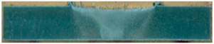
| Pin Profile | Butt Specimen | Scarf Specimen |
|---|---|---|
 |  | 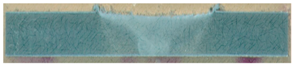 |
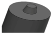 |  | 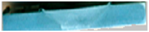 |
 |  | 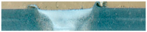 |
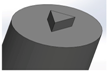 | 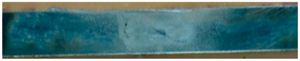 |  |
 |  |  |
| Process Parameter | Unit | Value |
|---|---|---|
| Tool rotational speed | Rpm | 900 |
| Welding speed | mm/min | 50 |
| Tool tilt angle | Degree | 1.5 |
| Tool shoulder diameter | mm | 20 |
| Tool shoulder surface | - | Flat |
| Pin diameter | mm | 7.3 |
| Pin length | mm | 4.5 |
| Pin Profile | Peak Load (KN) | UTS (MPa) | Elongation (%) | Impact Strength (Joule) |
|---|---|---|---|---|
| Tapered Cylindrical | 4.4 | 162 | 8 | 26 |
| Cylindrical | 4.1 | 160 | 11 | 24 |
| Square | 4.5 | 158 | 7 | 21 |
| Hexagonal | 3.5 | 117 | 5.3 | 22 |
| Triangular | 3.4 | 116 | 4.6 | 20 |
| Pin Profile | Peak Load (KN) | UTS (MPa) | Elongation (%) | Impact Strength (Joule) |
|---|---|---|---|---|
| Tapered Cylindrical | 3.3 | 129 | 7 | 16 |
| Cylindrical | 4.4 | 137 | 8 | 21 |
| Square | 1.6 | 77 | 5 | 09 |
| Hexagonal | 4.4 | 121 | 8 | 11 |
| Triangular | 1.7 | 63 | 3 | 18 |
© 2018 by the authors. Licensee MDPI, Basel, Switzerland. This article is an open access article distributed under the terms and conditions of the Creative Commons Attribution (CC BY) license (http://creativecommons.org/licenses/by/4.0/).
Share and Cite
Goel, P.; Siddiquee, A.N.; Khan, N.Z.; Hussain, M.A.; Khan, Z.A.; Abidi, M.H.; Al-Ahmari, A. Investigation on the Effect of Tool Pin Profiles on Mechanical and Microstructural Properties of Friction Stir Butt and Scarf Welded Aluminium Alloy 6063. Metals 2018, 8, 74. https://doi.org/10.3390/met8010074
Goel P, Siddiquee AN, Khan NZ, Hussain MA, Khan ZA, Abidi MH, Al-Ahmari A. Investigation on the Effect of Tool Pin Profiles on Mechanical and Microstructural Properties of Friction Stir Butt and Scarf Welded Aluminium Alloy 6063. Metals. 2018; 8(1):74. https://doi.org/10.3390/met8010074
Chicago/Turabian StyleGoel, Pankul, Arshad Noor Siddiquee, Noor Zaman Khan, Mohd Azmal Hussain, Zahid A. Khan, Mustufa Haider Abidi, and Abdulrahman Al-Ahmari. 2018. "Investigation on the Effect of Tool Pin Profiles on Mechanical and Microstructural Properties of Friction Stir Butt and Scarf Welded Aluminium Alloy 6063" Metals 8, no. 1: 74. https://doi.org/10.3390/met8010074
APA StyleGoel, P., Siddiquee, A. N., Khan, N. Z., Hussain, M. A., Khan, Z. A., Abidi, M. H., & Al-Ahmari, A. (2018). Investigation on the Effect of Tool Pin Profiles on Mechanical and Microstructural Properties of Friction Stir Butt and Scarf Welded Aluminium Alloy 6063. Metals, 8(1), 74. https://doi.org/10.3390/met8010074