Abstract
To address issues of residual stress concentration and deformation in large-scale multi-seam laser welding of tube-to-tubesheet, we established a 12 mm thick Q235 steel simulation model. The model considers the material’s high-temperature performance and mechanical properties. We designed three welding paths: sequential welding, block-by-block symmetrical welding, and inward–outward symmetrical radial welding. The welding simulation software InteWeld 4.0 was used to study the effects of these paths on deformation. Results showed that the inside-out symmetric radiation welding path disperses heat input effectively. It prevents stiffness reduction from local heat accumulation. By using symmetrically distributed shrinkage forces that offset each other, this path greatly inhibits deformation accumulation. The maximum deformation was only 1.6 mm—5.9% and 33% lower than with block-by-block symmetric welding (1.7 mm) and sequential welding (2.4 mm). This path also resulted in a uniform residual stress distribution, with a maximum stress of only 250 MPa, making it the best option for suppressing deformation.
1. Introduction
Shell and tube heat exchangers have excellent heat conversion effects and are widely used in petrochemical and other industrial fields as general thermal equipment [1,2]. Among them, tube-to-tubesheet welding is the core of the heat exchanger product manufacturing [3,4,5,6]. Its quality directly determines the whole heat exchanger’s manufacturing quality [7]. Traditional tube-sheet welding mainly relies on shielded metal arc welding (SMAW) or specialized machines. However, this method has several drawbacks. The process is complicated and labor intensive. It also has a high rework rate due to defects like slag inclusions and porosity. Consequently, production efficiency is low and costs remain high.
More importantly, arc welding uses a large heat source and high heat input. Tube-sheet structures have many welds spaced closely together [8], which causes heat to build up between adjacent welds and reduces quality. Laser welding is different. It offers concentrated heat and a small heat-affected zone [9]. It provides high efficiency and excellent quality, ensuring high-performance joints. As a result, laser welding is becoming a key direction for large-scale tube-sheet welding [10].
At present, there are few studies about laser welding in tube-to-tubesheet structures. Rosa Arias [11] built a system with a laser, an ABB six-axis welding robot, an optical seam tracker, and a machine-vision-based welding system. This setup automated welding for nickel alloy 690 tube-to-tubesheet joints. The European project ORBITAL developed an orbital laser welding head that improves positioning accuracy for orbital welding processes [12].
In view of the stress and deformation problems in tube-sheet welding, Xu et al. [13,14,15] used FEM to pinpoint high stress concentrations at the weld–base metal interface. Tait and Press [16] observed sinusoidal axial stress patterns induced by thermal gradients, while Han et al. [17] confirmed the significant non-uniform decay of residual stress along the axis of elliptical welds. AL-Badour et al. [18] demonstrated the feasibility of friction stir welding (FSW) for tube-to-tubesheet joints, characterizing the associated thermal gradients and stress distributions. In a comparative study, Kumar et al. [19] highlighted the superiority of high-energy beam processes, revealing that single-pass EBW/LBW significantly outperforms conventional multi-pass TIG welding in terms of reducing residual stress, HAZ size, and distortion. García González et al. [20] highlighted that geometric deviations in track welding exacerbate stress concentrations, necessitating precise sequence control and equipment positioning. Jangid et al. Shen et al. [21] attributed the formation of compressive root stresses during post-weld heat treatment to the mechanical interaction between tubes and sheets. Zeng et al. [22] reported that tube expansion elevates local residual stresses, which amplify stress amplitudes under thermal loads. Finally, Ibrahim [23] identified these thermally induced alternating stresses as the primary cause of fatigue failure in heat exchangers.
For tube-to-tubesheet welding sequence, Gao et al. [24] found that optimizing the post-internal-weld sequence in composite pipes reduces high residual stresses in both clad and base metals. Sheibani [25] used ABAQUS simulations to study how tube arrangement, spacing, and sequence affect residual stresses in tube-to-tubesheet joints. They verified that a good welding sequence effectively reduces residual stress. Farrahi [26] applied finite element analysis to simulate welding and post-weld heat treatment and calculate residual stresses for two tube-to-tubesheet structures. Tang et al. [27] developed a welding process for joints connecting thin-walled heat exchange tubes to thick tube sheets. They used a dual-layer manual GTAW technique with a zoned symmetrical sequence. This method reduced burn-through at tube ends and controlled tube sheet deformation. Chen et al. [28] simulated the welding process for titanium alloy tube sheets using a top-down symmetrical sequence. This approach lowered maximum deformation by 24.3%.
In summary, domestic and international scholars have systematically studied residual deformation in welded structures. They used numerical simulation and experimental validation and achieved great breakthroughs in the field. However, research on laser welding for tube-to-tubesheet structures is relatively limited. Although some studies have explored automation and local stress distribution, there is a lack of systematic research on how the welding sequence affects the global deformation in large-scale arrays. Most existing models focus on a few tubes, failing to capture the cumulative effect of stress when welding a full-scale tubesheet. Accordingly, this study employs numerical simulation to investigate the residual stress evolution and structural deformation in full-scale arrays, explicitly analyzing their key influencing factors. Building upon these insights, an optimized welding sequence is proposed to mitigate distortion.
2. Materials and Methods
2.1. InteWeld Welding Process Simulation Software
The welding process simulation and analysis were performed using InteWeld software (v4.0, Wuhan Zhongyu Cloud Simulation Technology Co., Ltd., Wuhan, China). Specifically, the complex joints module was utilized to calculate the temperature field, stress–strain evolution, and deformation during the laser welding process.
2.2. Establishment of Finite Element Mesh Model
The diameter of the large-scale tube-to-tubesheet joint arrays model is 600 mm. The tube sheet thickness is 12 mm and has 217 holes in the middle. The center distance between the tubes is 32 mm, arranged in a positive triangular way. The inner diameter of individual tubes is 20 mm, and the outer diameter is 25 mm. The connection between the tubes and the tube sheet is a flush type, as shown in Figure 1.
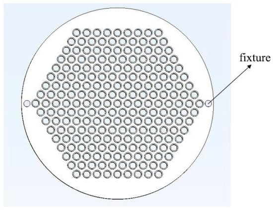
Figure 1.
Tube-to-tubesheet structure.
A denser mesh should be used near the weld to investigate stresses and deformations and enhance simulation accuracy. Sparser meshes may be used in plate regions farther from the weld, where temperature gradients are smaller, to improve computational speed and reduce computational load. A gradual transition is used between fine-mesh and coarse-mesh regions, as shown in Figure 2. The overall mesh partition is illustrated in Figure 3.
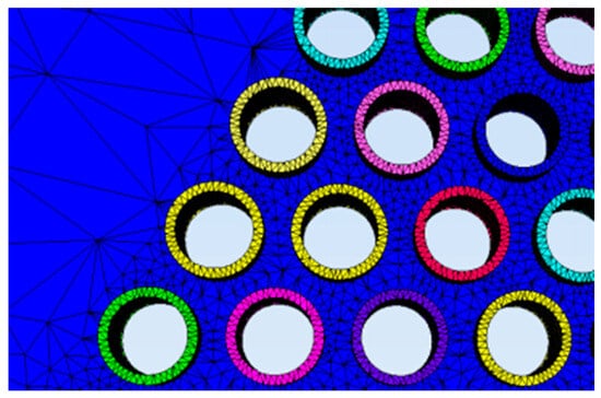
Figure 2.
Gradient network.
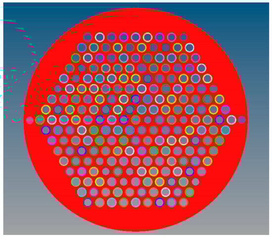
Figure 3.
Overall mesh model.
This simulation used a network of tetrahedral cells, which can form a network quickly and is adaptable to complex geometries. In total, the number of nodes is 1,174,601, as shown in Figure 3.
2.3. Material Properties
Q235 steel has good toughness, plasticity, and welding performance. The high-temperature mechanical parameters were derived from the built-in material database of the InteWeld software for low-carbon steel. The material performance parameters at different temperatures are shown in Table 1 and Table 2.

Table 1.
High-temperature material properties of Q235 steel.
Table 2.
High-temperature mechanical properties of Q235 steel.
2.4. Heat Source Model Calibration
The Gaussian heat source [29] is generally suitable for simulating conventional welding. However, in laser welding of thick plates, deep penetration creates a “keyhole effect.” This causes the weld depth to significantly exceed its width. Consequently, the accuracy of traditional Gaussian models is limited. To improve simulation accuracy, modified models such as conical [30] or double ellipsoidal heat sources [31] are commonly used. These models better describe the thermal conduction of the process. Therefore, this study utilizes a double ellipsoidal heat source. It is important to note that this study employs a thermo-mechanical Finite Element Method (FEM) rather than a Computational Fluid Dynamics (CFD) approach. This model is designed to accurately represent the volumetric heat distribution and deep penetration characteristic of the keyhole mode to predict the resultant temperature field and stress evolution, without directly resolving the multi-phase flow physics within the molten pool. Its heat flux distribution is calculated using the Goldak equation [32]. Frontal heat source heat flux distribution expression is as follows:
Rear heat source heat flux distribution expression is as follows:
In the formulas, f1 and f2 are typically set to 0.6 and 1.4, respectively. The constants a, b, c1, and c2 represent the geometric semi-axes of the molten pool; specifically, a is the semi-width in the transverse direction, b is the depth in the thickness direction, and c1 and c2 are the front and rear semi-lengths along the welding direction. Q denotes the effective power of the heat source. A moving coordinate system is established with the origin (0, 0, 0) fixed at the center of the heat source on the workpiece surface; thus, x, y, and z denote the coordinates in the transverse, depth, and welding directions, respectively.
To ensure the fidelity of the numerical simulation and address the limitations of empirical parameter selection, a preliminary process calibration experiment was conducted prior to the full-scale tube-to-tubesheet modeling. Unlike traditional manual trial-and-error methods, which are subjective and time consuming, this study utilized the automated heat source calibration module integrated into the InteWeld platform. The simulated molten pool morphology exhibits high consistency with the experimental cross-section, as illustrated in Figure 4. This automated calibration ensures that the numerical heat input distribution accurately reflects the actual laser energy density used in the experiment, providing a reliable thermal boundary condition for the subsequent stress analysis.
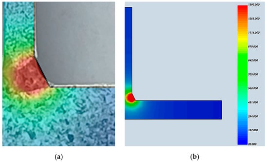
Figure 4.
Heat source calibration process: (a) Experimental macro-structure of the weld cross-section used as the calibration target; (b) Simulated molten pool geometry.
2.5. Simulation Design Scheme
Utilizing laser power is 1.8 kW, and the welding speed is 15 mm/s. The environmental temperature is 22 °C. Defining the mechanical boundary at the contact position between the fixture and the surface. The convective heat transfer coefficient was set at 15 (J/m2·s·°C) for all surfaces. The radiation coefficient of the radiative boundaries was set to 0.8.
Based on actual factory investigations and literature reviews, the welding sequences for multi-seam tube-to-tubesheet arrays are mainly divided into asymmetric welding sequences and symmetric welding sequences. The asymmetric welding sequence is row by row from top to bottom. The symmetric welding sequence includes two forms: one is dividing the entire tube-to-tubesheet arrays into four sections and performing symmetric welding on each section; the other is welding from the center to the outside in a symmetric, radial manner. In general, the symmetric welding sequence can relatively better control deformation. The welding sequences are shown in Figure 5.
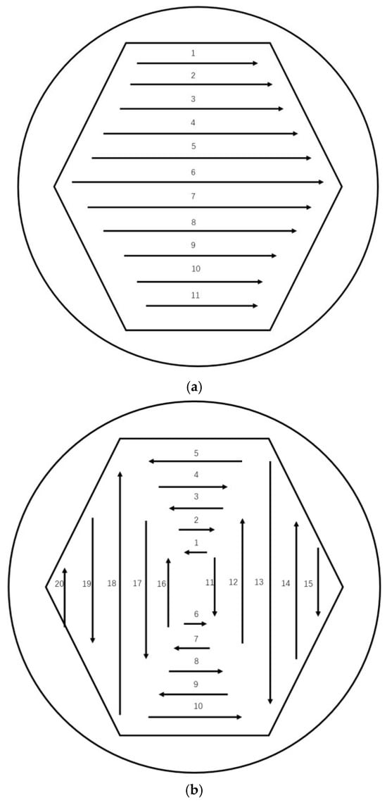
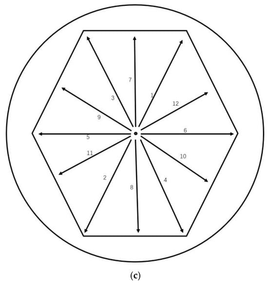
Figure 5.
Welding sequence scheme. (a) Diagram of sequential welding; (b) diagram of sectioned symmetric welding; (c) Diagram of symmetric welding.
The welding sequence optimization uses tubesheet axial deformation as the optimization criterion. Due to welding, deformation of different locations is different. Therefore, we used simulation to calculate the welding deformation and then extracted the deformation data at some specific points and the maximum deformation of the tube sheet. These deformations were compared and analyzed to optimize the welding sequence. The positions of the specific points are shown in Figure 6.
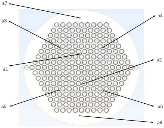
Figure 6.
Schematic of Measurement Points.
3. Result
3.1. Analysis of Stress Field Simulation Results
The stress distributions under the three schemes exhibit significant differences, as shown in Figure 7.
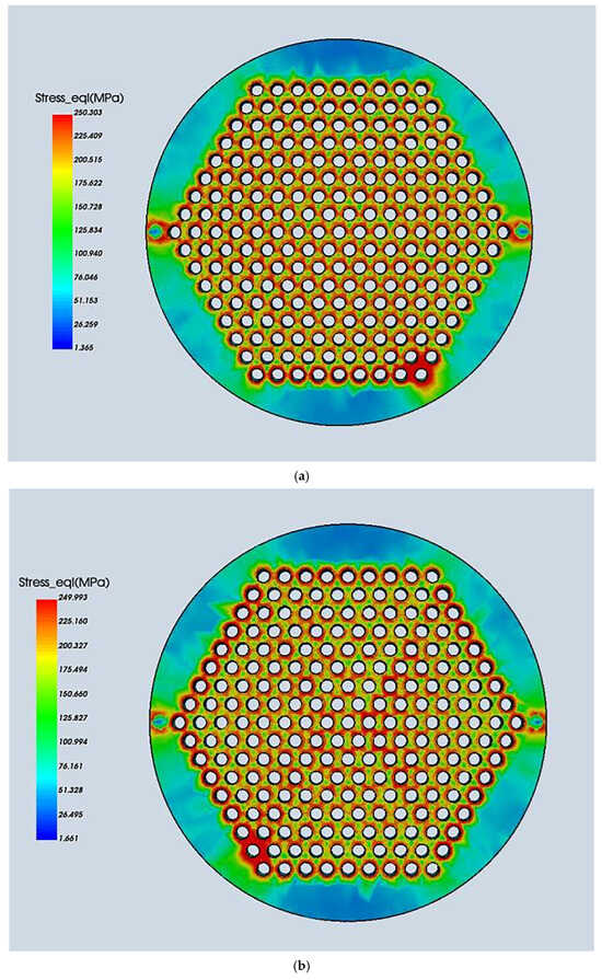
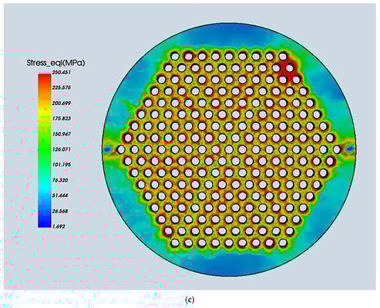
Figure 7.
Residual stresses of three welding sequences. (a) Scheme 1 residual stresses; (b) Scheme 2 residual stresses; (c) Scheme 3 residual stresses.
The residual stresses and maximum deformations are listed in Table 3.
Table 3.
Residual stresses and maximum deformations under three schemes.
Laser welding features high energy density, rapid cooling, and a concentrated heat source. These characteristics result in relatively low residual stresses. Residual stresses are similar for all three welding sequences, ranging from 240 to 250 MPa. Despite this, stress concentration occurs at the end of the weld in all three sequences. High stresses are clearly present near the bottom row of tube sheets in Scheme 1 and the outermost sheets in Scheme 2. This phenomenon is attributed to the following reasons:
(1) At the end of the process, the metal cools rapidly from a molten state to room temperature. This creates a steep temperature gradient. The hot metal contracts but is constrained by the surrounding cold solid metal, creating tensile stress
(2) During welding, the hot metal expands but is constrained, leading to plastic deformation. Upon cooling, it attempts to contract but is restricted by the elastic zone. This results in accumulated plastic strain.
(3) Welding adjacent seams reheats the previously welded sections. This reduces the constraint force of the surrounding solid metal. However, the constraint stress at the final weld position does not decrease.
Compared to Scheme 2, Schemes 1 and 3 exhibit more uniform residual stress distributions. They also show lower residual stresses near the welds. This is attributed to the following reasons:
(1) Scheme 2 uses segmented welding with concentrated circumferential welds in each segment. The simulation has a high welding speed and no time gap between adjacent welds. Consequently, the welds in the segment are completed quickly, causing high heat accumulation.
(2) Adjacent circumferential welds are close to each other. The subsequent weld reheats the previous one, increasing localized heat accumulation between them. Furthermore, the end of a weld reheats its starting point. Together, these factors concentrate heat in specific areas within a short time.
(3) The welding sequence in Scheme 1 and the outward radial welding in Scheme 3 avoid welding many joints in a small area at the same time. This reduces short-term heat accumulation.
In summary, heat accumulation and residual stress distribution in tube sheet welding are closely related to the welding path. These factors are also closely linked to tube sheet deformation.
3.2. Analysis of Deformation Results
Simulation results of welding deformation are shown in Figure 8, and the axial deformation of specified points, as well as the maximum axial deformation of the tube sheet under the three welding schemes, are presented in Table 4.
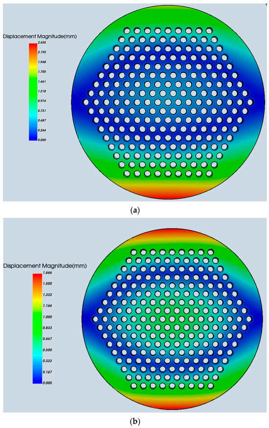
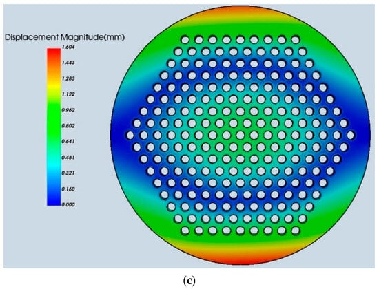
Figure 8.
Deformation Simulation Results of Three Welding Schemes. (a) Scheme 1 deformation; (b) Scheme 2 deformation; (c) Scheme 3 deformation.
Table 4.
Axial deformation of the tube sheet under three welding schemes (mm).
As shown in Figure 7a, the deformation contour of Scheme 1 (Sequential Welding) exhibits a distinct asymmetric distribution along the welding direction. The displacement magnitude gradually increases from the starting side to the finishing side. This phenomenon indicates a severe thermal accumulation effect. As the welding heat source moves sequentially, the heat cannot dissipate effectively, causing the temperature of the unwelded rear section to rise continuously. Consequently, the material’s yield strength decreases, and the localized thermal expansion leads to significant warpage at the terminal edge. This asymmetric behavior is further corroborated by the quantitative data in Table 4. Significant deformation discrepancies are observed between symmetrical points a1 and a2, as well as a7 and a8, confirming the presence of flexural deformation. The maximum deformation in the rear section reaches 2.4 mm. This value is notably higher than the 1.7 mm in Scheme 2 and 1.6 mm in Scheme 3. Both Schemes 2 and 3 use symmetrical welding paths. This is primarily because symmetrical welding distributes heat evenly, reducing thermal deformation differences. Welding stresses cancel symmetrically, minimizing residual stress accumulation. Furthermore, the symmetrical structure itself possesses high rigidity and symmetry. During welding, the contraction forces of the two welds mutually constrain each other, creating a self-constraining effect. Compared to Scheme 3, Scheme 2 uses a symmetrical sequential approach but welds in separate blocks. This leads to localized concentration of heat and stress. In contrast, Scheme 3 uses a symmetrical radial sequence from the inside outward. This further minimizes concentrated heat input and reduces deformation to just 1.6 mm. This confirms that Scheme 3 is the optimal welding sequence.
4. Conclusions
Through simulation of laser welding for tube-to-tubesheet structure, this paper draws the following conclusions:
(1) The peak residual stresses are similar in all schemes because the material yield strength and rigid constraints limit the maximum values. However, the welding sequence significantly changes the stress distribution. Scheme 3, which uses an inward-to-outward symmetrical radial sequence, exhibits a smaller extent of high-stress zones and a more uniform stress distribution.
(2) Symmetrical welding produces a more uniform distribution of deformation. Sequential welding (Scheme 1) caused the largest deformation of 2.4 mm due to unbalanced heat input. In contrast, symmetrical welding (Schemes 2 and 3) reduced deformations to 1.7 mm and 1.6 mm. Although both schemes use symmetry, Scheme 3 is more effective. The radial path in Scheme 3 spreads thermal energy across the tubesheet more evenly. It avoids the localized heat concentration that occurs in the block-by-block method (Scheme 2). This balanced thermal field creates a more uniform stress distribution, which directly leads to smaller and more stable deformation. Therefore, the inward-to-outward radial sequence is confirmed as the optimal path for high-quality tube-to-tubesheet welding.
Author Contributions
Conceptualization, C.C., X.K. and A.H.; Methodology, C.C., X.K. and B.W.; Software, B.W.; Resources, A.H.; Data curation, C.C.; Writing—original draft, C.C.; Writing—review and editing, X.K.; Supervision, A.H.; Project administration, C.C. and X.K.; Funding acquisition, A.H. All authors have read and agreed to the published version of the manuscript.
Funding
2022 Hubei Provincial KEY Research and Development Program Project: Research on Key Technologies and Equipment for Large-Scale Tube-Sheet Group Seam Laser Welding of New Heat Exchanger Pressure Vessels (Grant no. 2022BAA058).
Data Availability Statement
The original contributions presented in this study are included in the article. Further inquiries can be directed to the corresponding author.
Acknowledgments
During the preparation of this work, the author used Gemini 3 Pro Preview (Google LLC, Mountain View, CA, USA) in order to improve language. The authors have reviewed and edited the output and take full responsibility for the content of this publication.
Conflicts of Interest
The authors declare no conflicts of interest.
References
- Borjigin, S.; Zhao, W.; Fu, W.; Liang, W.; Bai, S.; Ma, J.; Meng, K.; Baoyin, H. Review of plate heat exchanger utilized for gas heat exchange. Renew. Sustain. Energy Rev. 2025, 210, 115224. [Google Scholar] [CrossRef]
- Ding, Y.; Guo, Q.; Guo, W.; Chu, W.; Wang, Q. Review of Recent Applications of Heat Pipe Heat Exchanger Use for Waste Heat Recovery. Energies 2024, 17, 2504. [Google Scholar] [CrossRef]
- Merah, N.; Al-Zayer, A.; Shuaib, A.; Arif, A. Finite element evaluation of clearance effect on tube-to-tubesheet joint strength. Int. J. Press. Vessel. Pip. 2003, 80, 879–885. [Google Scholar] [CrossRef]
- Bouzid, A.H.; Pourreza, M. Analysis of residual stresses in the transition zone of tube-to-tubesheet joints. J. Press. Vessel Technol. 2019, 141, 041201. [Google Scholar] [CrossRef]
- Ezuber, H.; Zakir Hossain, S.M. A review of corrosion failures in shell and tube heat exchangers: Roots and advanced counteractive. Heat Mass Transf. 2023, 59, 971–987. [Google Scholar] [CrossRef]
- Zhu, H.-S.; Zhai, J. The Unified Theory of Tubesheet Design—Part I: Theoretical Foundation. J. Pressure Vessel Technol. 2022, 144, 021303. [Google Scholar] [CrossRef]
- Thekkuden, D.T.; Mourad, A.H.I.; Bouzid, A.H. Failures and leak inspection techniques of tube-to-tubesheet joints: A review. Eng. Fail. Anal. 2021, 130, 105798. [Google Scholar] [CrossRef]
- Lei, T.; Wu, C.; Rong, Y.; Huang, Y. The development of tube-to-tubesheet welding from automation to digitization. Int. J. Adv. Manuf. Technol. 2021, 116, 779–802. [Google Scholar] [CrossRef]
- Sanati, S.; Nabavi, S.F.; Farshidianfar, A. Laser wobble welding modeling process: A comprehensive review of fundamentals, methods, heating, and solidification modes. J. Manuf. Process. 2024, 131, 1703–1739. [Google Scholar] [CrossRef]
- Srivastava, D.; Chadha, U.; Gunreddy, N.; Saini, N.K.; Matara, N.N.; Machindar, O.; Mishra, U.V.; Khanna, M.; Kishore, S.R.; Selvaraj, S.K. A brief review on the Tube-to-Tube plate welding process. Mater. Today: Proc. 2022, 64, 870–882. [Google Scholar] [CrossRef]
- Arias, R.; Vaamonde, E.; Vandewynckèle, A.; Piñeiro, E.; Veron, P. Laser welding of tube to tube-sheet joint in steam generators for nuclear power plants. In ICALEO® 2010, Proceedings of the 29th International Congress on Laser Materials Processing, Laser Microprocessing and Nanomanufacturing, Orlando, FL, USA, 10–14 October 2010; Laser Institute of America: Orlando, FL, USA, 2010. [Google Scholar]
- Vandewynckéle, A.; Vaamonde, E.; Fontán, M.; Herwig, P.; Mascioletti, A. Laser Welding Head Tailored to Tube-Sheet Joint Requirements for Heat Exchangers Manufacturing. Phys. Procedia 2013, 41, 144–152. [Google Scholar] [CrossRef]
- Xu, S.; Wang, W. Numerical investigation on weld residual stresses in tube to tube sheet joint of a heat exchanger. Int. J. Press. Vessel Pip. 2013, 101, 37–44. [Google Scholar] [CrossRef]
- Xu, S.; Zhao, Y. Using FEM to determine the thermo-mechanical stress in tube to tube–sheet joint for the SCC failure analysis. Eng. Fail. Anal. 2013, 34, 24–34. [Google Scholar] [CrossRef]
- Wan, Y.; Jiang, W.; Luo, Y. Using X-ray diffraction and finite element method to analyze residual stress of tube-to-tubesheet welded joints in a shell and tube heat exchanger. J. Press. Vessel Technol. 2017, 139, 051405. [Google Scholar] [CrossRef]
- Tait, R.B.; Press, J. An experimental study of the residual stresses, and their alleviation, in tube to tube-sheet welds of industrial boilers. Eng. Fail. Anal. 2001, 8, 15–27. [Google Scholar] [CrossRef]
- Han, X.M.; Tan, J.Z.; Wang, R.Q.; Yin, W.-H. A study on welding residual stress in elliptical tube to tube sheet joint of a phthalic anhydride switch condenser. Procedia Eng. 2015, 130, 544–551. [Google Scholar] [CrossRef]
- Al-Badour, F. Finite Element Modeling of Hybrid Friction Diffusion Welding of Tube-Tubesheet Joints. J. Press. Vessel Technol.-Trans. ASME 2021, 143, 011506. [Google Scholar] [CrossRef]
- Jangid, M.K.; Roy, V.; Kamble, M.T.; Singh, P.K. Analyzing the influence of welding process selection on residual stresses in tube-to-tubesheet welded joints. J. Weld. Join. 2024, 42, 495–513. [Google Scholar] [CrossRef]
- García González, J.; Hernández-Ortega, J.J.; Jiménez-Ballesta, A.E.; Pedreño, R.Z. Analysis of Tube-to-Tubesheet Welding in Carbon Steel Heat Exchangers of a Double Plate Header Box. Materials 2021, 15, 261. [Google Scholar] [CrossRef] [PubMed]
- Shen, K.; Zhang, Z.; Jiang, W.; Luo, Y.; Su, H.; Zhang, Y. Generation of compressive residual stress at the root of tube-to-tubesheet welded joints in a heat exchanger. Int. J. Press. Vessel. Pip. 2022, 200, 104848. [Google Scholar] [CrossRef]
- Zeng, Q.; Li, Y.; Zhang, G.; Shi, J.; Li, C.; Zhang, Z.; Su, X. Influence of neighbouring tube expansion on the residual stress of tubesheet with single-row holes. Int. J. Press. Vessel. Pip. 2022, 197, 104651. [Google Scholar] [CrossRef]
- Ibrahim, S.E. Impact of fatigue on tube-to-tubesheet welded joints in heat exchanger. J. Fail. Anal. Prev. 2022, 22, 1631–1636. [Google Scholar] [CrossRef]
- Gao, Z.; Han, B.; Li, L.; Ma, G.; Niu, S. Numerical simulation of residual stress in post internal-welding process of bimetal composite pipe and optimization of welding sequence. Int. J. Press. Vessel. Pip. 2022, 199, 104730. [Google Scholar] [CrossRef]
- Sheibani, R.; Rabiezadeh, A.; Jahedi, R.; Mohammadi, M. Effect of Tube Arrangement on the Welding of the Tube-to-Tubesheet Joint of Shell-and-Tube Heat Exchangers Using the Finite Element Method. J. Mater. Eng. Perform. 2025, 34, 3618–3632. [Google Scholar] [CrossRef]
- Farrahi, G.H.; Minaii, K.; Chamani, M.; Mahmoudi, A.H. Effect of residual stress on failure of tube-to-tubesheet weld in heat exchangers. Int. J. Eng. 2019, 32, 112–120. [Google Scholar]
- Tang, Z.; Wang, X.; Chen, J.; Huang, Y.; Liang, L. Welding of tubesheet and heat exchange tubes in heat exchangers. MW Met. Form. (Hot Work.) 2015, 2, 46–48. (In Chinese) [Google Scholar] [CrossRef]
- Chen, T.; Lu, L.; Lin, T.; Xu, S.; Feng, G.; Liu, C.; Chen, J. Simulation of Welding Process of Titanium Alloy Pipe-sheet Structure based on ABAQUS. Electr. Weld. Mach. 2024, 54, 96–104. [Google Scholar]
- Eagar, T.W.; Tsai, N.S. Temperature fields produced by traveling distributed heat sources. Weld. Res. Suppl. 1983, 62, 346–355. [Google Scholar]
- Wu, C.S.; Wang, H.G.; Zhang, Y.M. A new heat source model for keyhole plasma arc welding in FEM analysis of the temperature profile. Weld. J. 2006, 85, 284. [Google Scholar]
- John, G.; Aditya, C.; Malcolm, B. A new finite element model for welding heat sources. Metall. Trans. B 1984, 15, 299–305. [Google Scholar]
- MitraAbhishek, P.N.S.; Janaki Ram, G.D. Estimation of residual stresses in an 800 mm thick steel submerged arc weldment. J. Mater. Process. Technol. 2016, 229, 181–190. [Google Scholar]


Disclaimer/Publisher’s Note: The statements, opinions and data contained in all publications are solely those of the individual author(s) and contributor(s) and not of MDPI and/or the editor(s). MDPI and/or the editor(s) disclaim responsibility for any injury to people or property resulting from any ideas, methods, instructions or products referred to in the content. |
© 2026 by the authors. Licensee MDPI, Basel, Switzerland. This article is an open access article distributed under the terms and conditions of the Creative Commons Attribution (CC BY) license.