Abstract
This study investigates the technological and chemical causes of early zinc-coating degradation on cold-formed steel sections produced from DX51D+Z140 galvanized coils. Commercially manufactured products exhibiting early corrosion symptoms were used in this study. The entire processing route, which included strip preparation, cold rolling, hot-dip galvanizing, passivation, multi-roll forming, storage, and transportation to customers, was analyzed with respect to the residual surface chemistry and process-related deviations that affect the coating integrity. Thirty-three specimens were examined using electromagnetic measurements of coating thickness. Statistical analysis based on the Cochran’s and Fisher’s criteria confirmed that the increased variability in zinc coating thickness is associated with a higher susceptibility to localized corrosion. Surface and chemical analysis revealed chloride contamination on the outer surface, absence of detectable Cr(VI) residues indicative of insufficient passivation, iron oxide inclusions beneath the zinc coating originating from the strip preparation, traces of organic emulsion residues impairing wetting and adhesion, and micro-defects related to deformation during roll forming. Early zinc coating degradation was shown to result from the cumulative action of multiple technological (surface damage during rolling, variation in the coating thickness) and environmental (moisture during storage and transportation) parameters. On the basis of the obtained results, a methodology was proposed to prevent steel product corrosion in industrial conditions.
1. Introduction
In the context of the growing demand for rapid restoration of damaged housing stock, particularly resulting from full-scale military actions in Ukraine [1], increased attention is focused on structural materials that ensure reliability, fast installation, and cost efficiency in construction [2]. Window systems are among the most frequently damaged building elements due to blast waves and debris, and their repair or replacement requires the availability of standardized load-bearing components [3]. Cold-formed steel sections (CFS) from galvanized steel are widely used as reinforcement elements in window design, facade systems, and lightweight structural applications (Figure 1); they provide sufficient stiffness, geometrical stability, and ease of installation [4]. Zinc coatings are commonly applied to protect the steel against corrosion. However, cases of premature coating degradation are reported even under relatively mild service conditions, thus necessitating additional measures to ensure long-term durability [5].
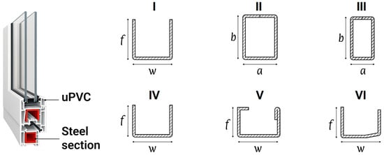
Figure 1.
Cold-formed steel reinforcement sections for unplasticized polyvinyl chloride (uPVC) window design, where f is the flange height, w is the web width, a is the section width, and b is the section height; I, IV, VI—open thin-walled sections, II, III—closed rectangular hollow sections (RHS), and V—a lipped open section with a 180° folded flange (LC).
Corrosion of steel remains a global engineering challenge, leading to material loss, reduced structural integrity, and premature failure of the built structures [6]. According to the World Corrosion Organization, the direct global cost of corrosion reaches 1.3–1.4 trillion EUR annually, which corresponds to 3.1–3.5% of national GDP [7]. The corrosion process is inherently multifactorial and is governed by the material characteristics, environmental exposure, and operational conditions [8,9]. This complicates reliable lifetime prediction and often results in the use of excessive safety margins and increased material consumption [6]. Therefore, material quality becomes particularly important for cold-forming technologies, where losses may arise not only from plastic deformation but also from degradation of protective coatings. As demonstrated in [10], optimization of forming parameters during preliminary forming passes can reduce energy and force requirements by more than a factor of four and decrease trim loss to approximately 22%.
White rust formation is common on galvanized steel products and represents a form of atmospheric corrosion developing under the combined action of moisture, high relative humidity, aggressive aerosols, and insufficient surface passivation [11,12]. This corrosion mechanism degrades the zinc coating, deteriorates surface appearance, and ultimately exposes the steel substrate, reducing structural reliability during service. Its development is intensified by increased humidity levels and more frequent temperature fluctuations associated with global climate change [13,14,15], although these factors act primarily as accelerating rather than initiating mechanisms. As demonstrated in [12], residual contaminants remaining on the steel surface prior to galvanization significantly affect the intensity of white rust (ZnO) formation; in particular, the presence of sulfur, chlorine, and oxygen at the substrate–coating interface promotes corrosion initiation, underscoring the critical role of surface preparation. Exposure to chemically aggressive environments arising from winter road de-icing agents, agricultural fertilizers and disinfectants, or marine atmospheres compromises the protective function of zinc coatings, making CFS susceptible to localized corrosion even for the highest quality steel products [16].
Formed galvanized steel components are exposed during service to cyclic loading, vibrations, and environmental influences [17]. Understanding of their behavior in such complex conditions is essential for identifying zones susceptible to localized mechanical damage or coating degradation. As shown in [18], the presence of surface defects, such as scratches acting as stress concentrators, significantly affects the integrity limit of structural elements depending on the local stress–strain conditions. The study [19] demonstrated that contact interactions at crack edges in formed parts play an important role in predicting coating behavior under bending and tensile loading. In [20], the CFS geometry showed its influence on stress distribution during service, as well as its relevance for the local stability of protective coatings and the response to combined bending and constrained torsion. Accordingly, cold-formed galvanized steel sections are required to meet a set of mechanical and technological criteria, including sufficient stiffness and strength at minimal weight, geometric accuracy, shape stability during installation, and resistance to mechanical and vibrational loads [20,21]. Corrosion resistance is commonly provided by double-sided zinc coatings (e.g., DX51D+Z140, Z140) in accordance with EN 10346:2015 [22]. However, deviations in surface quality, coating uniformity, or handling and storage conditions may still promote early-stage corrosion, even in newly manufactured sections.
One of the key factors governing the quality and durability of protective coatings on steel surfaces is the condition of the substrate prior to coating application. Artiukh et al. [23] examined this aspect using polymer adhesives as a model system and established a clear correlation between the bond strength and surface roughness, residual moisture, drying conditions, and application temperature—the parameters that are directly relevant to passivation quality and zinc adhesion during production of CFS.
The chemical composition of steel also affects corrosion resistance and adhesion of the metallic or polymeric coatings. As demonstrated by Kalisz et al. [24], yttrium additions modify non-metallic inclusions by reducing their size and improving their distribution, thereby enhancing structural homogeneity and oxide film formation, which limit the penetration depth of aggressive agents. The production route of steel sections further influences corrosion behavior and subsequent coating degradation during service. In [25], Laser Powder Bed Fusion (LPBF) was shown to improve wear resistance without compromising corrosion performance, highlighting the importance of forming conditions and post-processing in determining surface durability.
A promising direction is the use of advanced steel coating methods, particularly arc deposition and chemical alloy plating. Study [26] demonstrated that the structural heterogeneity and phase morphology of arc-deposited surface layers strongly influence erosion resistance under thermal loading, while ref. [27] showed that chemically deposited Ni–P–W coatings significantly improve the corrosion resistance of steel reinforcement in chloride environments, effectively reducing substrate damage and confirming their applicability in aggressive conditions.
It is important to note that the production of formed metal components involves several sequential stages [28], including cold rolling, coil galvanization, slitting into strips, and subsequent roll forming, with additional influence from transportation and storage conditions. Each stage may introduce risks of defect formation associated with inadequate surface cleaning, insufficient passivation, limited control of geometric tolerances, air humidity, or process water quality. As demonstrated by Kurpe et al. [29,30], the quality of hot-rolled slabs used as feedstock for cold rolling is governed by rolling parameters applied on Steckel mills [29] and conventional wide-strip hot rolling mills (HRM) [30]. Key factors include the reduction distribution between rolling stands, rolling speed, temperature prior to descaling, and cooling conditions after coiling. These parameters directly determine the initial surface condition of the slab and thereby influence the effectiveness of subsequent pickling, galvanizing, and, to some extent, passivation processes in the production of galvanized CFS.
Kukhar et al. [31] showed that systematic approaches to coil steel quality monitoring, using Deming cycle tools, Pareto analysis, and Shewhart control charts, reduce variability not only in mechanical properties but also in surface quality, which is critical for downstream processing. In this context, accurate experimental characterization of strip properties enables the identification of deviations such as coating inhomogeneity, local surface defects, and zinc coating thickness variations after galvanizing, allowing timely diagnosis of quality degradation in cold-rolled strips and CFS products.
Analytical and statistical modeling approaches are increasingly applied to the study of formed metal products to describe material deformation, geometry evolution, load distribution, and final quality parameters [32,33]. In [32], universal parametric dependencies were proposed to reconstruct the contour evolution of formed elements at different stages of the technological process. Statistical modeling based on full factorial experiments was applied in [33], where regression models were used to analyze the influence of technological factors on product characteristics and to assess model adequacy using statistical criteria. Such approaches are directly applicable to the analysis of zinc coating inhomogeneity, enabling diagnosis of zinc coating thickness variations, process stability, and identification of deviation sources in finished CFS.
The integration of multi-level analytical, chemical, and statistical methods with adaptive feedback was shown in [34] to improve the efficiency of technological investigations, particularly in the characterization of the coating degradation through correlation analysis and identification of critical factors. Studies [35,36] examined the formation of local defects under intense cold plastic deformation, demonstrating that tool geometry, forming transition design, and energy parameter variation strongly influence material flow, strain localization, and defect development—factors that are especially relevant prior to protective coating application. In [37], deformation localization control during the forming of double-curvature panels reduced shape deviations from 1.67 mm to 0.3 mm, which correspond to an improvement in geometric accuracy of over 80%, highlighting the importance of intermediate quality control in cold-formed steel manufacturing. More recent approaches include the use of impulse friction to modify surface layer structure and improve coating adhesion, as reported in [38], while effective thermal control using thermocouples, pyrometers, and PID-based regulation remains essential across processes such as annealing, cold rolling, and hot-dip galvanizing [39]. Despite extensive studies on galvanized steel corrosion, existing literature predominantly addresses individual stages of production or controlled laboratory conditions and does not systematically link process deviations across the full DX51D+Z140 production chain to premature white or brown rust formation on real cold-formed sections.
The impetus for this study was the premature appearance of white rust on CFS prior to service, which resulted in justified customer claims. The investigated products were manufactured from galvanized strips supplied by a cold-rolled steel coil (CRC) producer, subsequently roll-formed by a CFS manufacturer, and delivered to a construction-related end user. After roll forming, the CFS were stored outdoors under winter conditions at the end user’s storage for approximately two months, after which clear symptoms of corrosion/zinc coating degradation were detected. Accordingly, the technical investigation covered successive stages of the production–logistics chain, including galvanized coil production, roll forming, transportation, and outdoor storage of the delivered CFS.
The aim of this study is to identify and substantiate the technological and chemical factors responsible for early zinc coating degradation in the CFS made from DX51D+Z140 galvanized steel and applied in unplasticized polyvinyl chloride (uPVC) window design. To achieve this aim, the critical stages of the manufacturing process and post-processing conditions were analyzed: coil preparation, galvanizing, roll forming, transportation, and storage. Experimental evaluation of the zinc coating thickness, its variability, and compliance with Z140 standard requirements was carried out. Surface and subsurface contaminants affecting the coating continuity and adhesion were characterized. The established relationships between the technological parameters, coating inhomogeneity, and the observed corrosion damage in the finished steel sections allowed us to provide process optimization recommendations, which are valuable not only for the industrial partner of this project but also for a broad steel manufacturing community.
2. Methodology
2.1. General Concept
The research methodology was developed to enable a comprehensive analysis of the technological process for manufacturing CFS from galvanized steel. It focused on identifying critical production stages, selecting representative specimens, and applying physicochemical and instrumental methods to evaluate the zinc coating. The logical and structural framework of the study is presented in Figure 2.
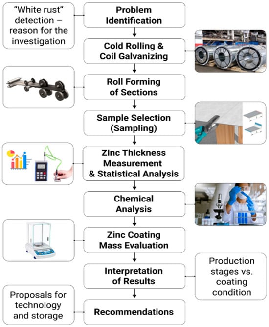
Figure 2.
Logical and structural framework of the research methodology.
It should be noted that the strip blank specimens and the CFS examined in this study correspond to different stages of the same production–logistics chain. The strip blanks were sampled from residual galvanized coils stored at the CRC manufacturer and represent the initial reference condition of the zinc coating. In contrast, the CFS were sampled after roll forming and subsequent outdoor storage under winter conditions, during which early corrosion damage developed. In addition, specimens cut from hot-dip galvanized CRC supplied by a Polish manufacturer were investigated in parallel, allowing a comparative assessment of the initial zinc coating quality.
2.2. Analysis of Technological Processes in the Production of Galvanized Coil Steel at the Cold Rolling Mill
To identify potential factors that may contribute to the degradation of zinc coating on CFS, a structural and technological analysis was conducted on the full production cycle for galvanized coil steel at a metallurgical plant (Figure 3).
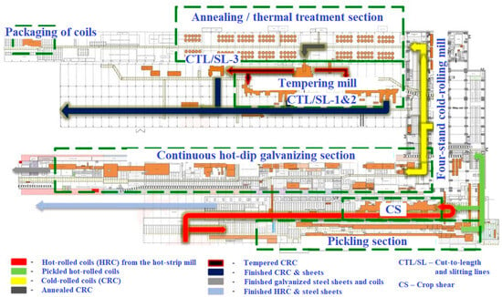
Figure 3.
Organization of galvanized coil production at the cold rolling mill (adapted from Ref. [28]).
The methodology involved the analysis of individual stages of the process, with a focus on technological operations that directly affect the quality and stability of the zinc protective coating. The analysis was based on the review of technical documentation and internal regulations of the plant, examination of semi-finished (i.e., galvanized strips), and expert interviews with workshop personnel. Particular attention was paid to the stages of acid pickling of hot-rolled coils, strip rinsing and drying, cold rolling operations, hot-dip galvanizing, chromate passivation, and lubrication [28,40].
In CRC production, passivation on the continuous hot-dip galvanizing line (Sendzimir-type, soviet-assembled) is implemented in two defined technological modes: (a) spraying of the passivating solution onto both sides of the strip through nozzle systems; (b) spraying onto the upper strip surface only. Additionally, the treatment of the lower surface is carried out by solution transfer via rolls immersed in the passivating bath. The second mode is applied more frequently for economic reasons.
2.3. Analysis of the Manufacturing Process of CFS from Galvanized Coil Steel
The technological process of CFS production was analyzed based on a structural and functional assessment of the production line, which included coil unwinding, slitting into strips, multi-roll forming, profile cutting to length, and final packaging (Figure 4).
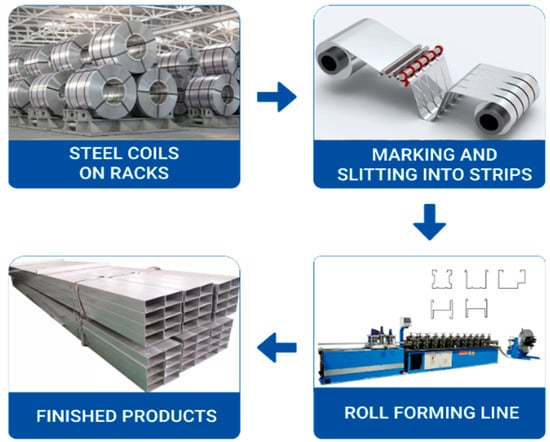
Figure 4.
Organization of cold-formed steel sections production from galvanized coil steel.
The sources of information included routing documentation, technical descriptions of the production line, visual observations of the process, and surface inspections of finished products. During the analysis, the sequence of slit strip passage through forming stands, the operation of guides, flying saw cutting mechanisms, and receiving tables was documented. Particular attention was given to conditions under which mechanical damage to the zinc coating could occur—such as the presence of abrasive particles in contact zones, strip misalignment, lack of roll parallelism, or improper adjustment of pressure settings. Typical defect localization zones were also examined, including profile edges, bending areas, and contact regions with the rollers [41].
The bending radii applied during roll forming were defined by the existing production technology of the CFS manufacturer and were not varied within the scope of this study. For the investigated strip thickness range (1.48–1.50 mm), the minimum bending radius used in the final forming stand was 2.5–3.0 mm. Such radii are commonly applied in industrial roll forming of galvanized steel sections and are intended to reduce the risk of zinc coating cracking or delamination during bending.
In addition, the conditions of transportation and storage of finished products were assessed: packaging methods, presence of ventilation openings, maintenance of tilt angles for moisture drainage, and the potential for condensation in tightly stacked bundles.
All observations were correlated with defects identified on actual CFS specimens, which allowed for the determination of possible cause-and-effect relationships between the production process and coating degradation.
2.4. Specimen Selection for Testing
For the purposes of this study, specimens were collected both from strip blanks and from finished CFS exhibiting signs of corrosion (Figure 5), manufactured from DX51D+Z140 galvanized coil steel. The selection process was deliberate and accounted for raw material origin, geometric parameters, presence of visible defects, and service load conditions. In what follows, the symbol t refers to the thickness of the sheet material, specifically, the thickness of the strip blanks and the wall thickness of the CFS.
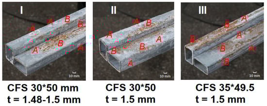
Figure 5.
Typical corrosion marks on cold-formed galvanized steel sections of different cross-sections (I–III): representative areas with white rust products on the zinc coating (A) and localized corrosion associated with oxidation of the steel substrate (B).
From each strip blank and finished section, rectangular control specimens with a size of 30 × 20 mm were cut. When extracting specimens from the section, the original geometry of bends and corners was preserved, and the location on the surface was documented (central zone, edge, bend area, etc.). The sampling layout for profile specimens is shown in Figure 6.
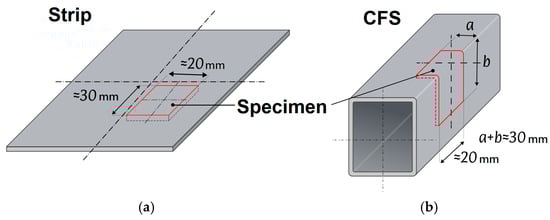
Figure 6.
Diagram of specimen extraction from strip (a) and CFS (b).
The specimens were labeled based on the material origin, geometric characteristics, and sampling conditions. Each specimen was recorded in a tracking log and prepared for subsequent measurements and chemical analysis. Storage was carried out in individual labeled containers under controlled conditions.
In total, three series of strip blanks were analyzed, from which specimens were extracted (see Figure 7):
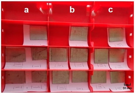
Figure 7.
Test specimens cut from flat galvanized strip blanks prior to roll forming: (a) strip blank “Poland” (Series I); (b,c) blanks from strips (Series II) and (Series III), supplied by the same manufacturer but certified separately.
- Series I: t = 1.03 mm (manufactured in the Republic of Poland);
- Series II and III: t = 1.35 mm and 1.5 mm, respectively (manufactured in Ukraine).
The Polish-made specimens were treated as a reference series for comparative evaluation of zinc coating stability and its performance during subsequent roll forming.
Additionally, three series of CFS were examined, from which specimens were cut (see Figure 8):
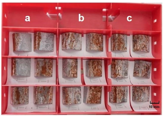
Figure 8.
Test specimens cut from cold-formed hollow sections for chemical testing: (a) CFS (IV)—30 × 50 mm, t = 1.48–1.5 mm; (b) CFS (V)—30 × 50 mm, t = 1.5 mm; (c) CFS (VI)—35 × 49.5 mm, t = 1.5 mm.
- Series IV and V: cross-section of 30 × 50 mm, t = 1.48–1.5 mm and t = 1.5 mm respectively;
- Series VI: cross-section of 35 × 49.5 mm, t = 1.5 mm.
Flat strip specimens (see Figure 7) were used as an undeformed reference, while specimens extracted from cold-formed hollow sections (see Figure 8) represent the coating condition after bending and forming operations.
The examined sections were manufactured from coils of similar steel grade but with different production histories, enabling a comparative analysis of variations in technological conditions. All three CFS specimens exhibited visible signs of corrosion damage to varying degrees, including both white and brown rust.
2.5. Zinc Coating Thickness Measurement
The thickness of the zinc coating hi on specimens cut from strip blanks and CFS was measured using a NOVOTEST TP-1 (Novomoskovsk, Ukraine) electromagnetic gauge with automatic averaging of results. A total of N = 33 specimens were analyzed: 15 from strip blanks and 18 from CFS (see Figure 7 and Figure 8). All the specimens were divided among three series of strip blanks (5 specimens per blank) and three series of finished CFS (6 specimens per CFS). The investigated strip blanks included: Series I—blanks of Polish origin, t = 1.03 mm (Figure 7a); Series II—Ukrainian-made blanks, t = 1.35 mm (Figure 7b); Series III—Ukrainian-made blanks, t = 1.5 mm (Figure 7c). Additionally, three types of CFS produced from these blanks were studied: two CFS with cross-sections of 30 × 50 × (1.48–1.5) mm (Series IV, Figure 8a) and 30 × 50 × 1.5 mm (Series V, Figure 8b); one CFS with a cross-section of 35 × 49.5 × 1.5 mm (Series VI, Figure 8c). The average zinc coating thickness (), relative error (δ), and variance (S2) were calculated for each series.
For each specimen, independent measurements were performed—five measurements per specimen from strip blanks (n = 5) and six per specimen from CFS (n = 6)—to determine the zinc coating thickness () at different locations. Subsequently, the arithmetic mean thickness () was calculated, followed by the absolute error (Δh), standard deviation (), and both absolute (Δh) and relative () measurement errors [33,42]:
The typical zinc coating thickness according to the Z140 standard (EN 10346:2015) is 10 μm, with a recommended range of 7–15 μm. The comparison was carried out using the actual results obtained from strip blanks (t =1.03–1.5 mm) and finished CFS (t = 1.5 mm and t = 1.48–1.5 mm), taking into account the dimensional types. The data processing was performed separately for each specimen (with the total number of measurements, i.e., the full sample size, equal to N = 33). The results of statistically consistent specimens were considered valid and used for further analysis.
To verify the reliability of the results and the statistical consistency of the measurement series for each specimen, the Cochran criterion () was used to assess homogeneity, and the Fisher F-test (F) was used to evaluate the adequacy of the model [33,42]:
where
and —tabular critical values of criteria. The calculations were performed at a confidence level of α = 0.95. Results that satisfied the condition = 0.544 and = 14.02 were considered statistically valid. The data processing was carried out separately for each series, followed by generalization in a summary table. In addition to the adequacy variance , the total overall variance was also calculated:
where
Particular attention was paid to the specimens with the greatest deviations or reduced zinc coating thickness relative to the standard.
2.6. Chemical Analysis of the Specimens
The analysis was conducted to identify surface and subsurface contaminants that could lead to adhesion failures or localized corrosion of the zinc coating. The same 33 specimens were used for the study (15 from strip blanks and 18 from CFS; see Figure 7 and Figure 8). The analysis was performed for five indicators (see Table 1): the presence of chloride ions (Cl−), sulphate ions (SO42−), hexavalent chromium (Cr(VI)), iron oxides (FeO/Fe2O3), and residual processing emulsion.

Table 1.
Methods for detecting surface contaminants on galvanized steel.
Chloride ions (Cl−) were detected via a classical reaction with AgNO3 solution, with the formation of a visible white AgCl precipitate. Sulphates (SO42−) were identified by adding BaCl2 solution, which results in the formation of insoluble BaSO4. Cr(VI) analysis was carried out after dissolving the coating in HNO3, followed by the addition of H2SO4, H3PO4, and 0.5% diphenyl carbazide solution in acetone. The presence of Cr(VI) was confirmed by the appearance of a red-violet coloration. Microscopic analysis of iron oxides (FeO/Fe2O3) was conducted using a methodology adapted from ISO 8407:2021 [43] and ISO 1463:2021 [44].
Observations were made using an Olympus GX51 optical metallographic microscope (Hachioji, Tokyo, Japan, up to 1000× magnification, reflected light illumination), specifically configured for analysing the topography of metallic surfaces. Detection of organic residues (from emulsions such as “Universal–1TS” or “Agrinol–HP”) involved acid dissolution in HNO3, followed by solvent extraction and Thin Layer Chromatography (TLC) on paper. The presence of organic contaminants was confirmed by characteristic staining on the sorbent.
2.7. Evaluation of Zinc Coating Mass
The mass of the zinc coating was determined using the gravimetric dissolution method in accordance with ISO 1460:2020 [45]. For each specimen, the zinc coating was completely dissolved chemically without affecting the base metal. The mass difference before and after treatment was then measured. Dissolution was performed at room temperature using a freshly prepared solution of hydrochloric acid (HCl) with a corrosion inhibitor (hexamethylenetetramine). Each specimen was weighed using an analytical balance (accuracy ± 0.1 mg) prior to dissolution. After complete removal of the zinc coating, the specimens were rinsed with distilled water, dried, and reweighed. The coating mass was calculated as the difference between the initial and final specimen mass, normalized to the controlled surface area. The results were expressed in g/m2. For each series, at least three measurements were taken, followed by the calculation of the mean value and standard deviation.
A summary table of the applied methods and control checkpoints, used to concisely present all research stages with reference to the method, specimen type, and expected outcome, is provided below (see Table 2).
Table 2.
General structure of the methodology.
All methods were aimed at establishing correlations between production parameters, chemical contaminants, and the actual condition of the zinc coating at the time of analysis. The integrated application of the described techniques made it possible not only to identify the presence of coating defects but also to determine their potential technological origin. This provided the foundation for interpreting the results and formulating conclusions.
3. Results
3.1. Process Analysis for Galvanized Steel Coil Production in the Cold Rolling Shop (CRS)
Galvanized steel coil production in the Cold Rolling Shop comprises sequential pickling of hot-rolled coils, cold rolling on a four-high mill, continuous hot-dip galvanizing, passivation, and optional oiling. Deviations in surface preparation, rolling conditions, or post-galvanizing treatment may adversely affect zinc coating integrity and corrosion resistance already at the coil stage. The process analysis revealed several technological factors that can contribute to premature zinc-coating degradation prior to roll forming.
1. Non-uniform zinc coating thickness. Visual inspection and localized thickness measurements showed a systematic reduction of zinc coating in the edge zones of the strip, which is attributed to melt drainage and cooling characteristics during galvanizing, thus rendering edge regions more susceptible to corrosion initiation.
2. Mechanical surface damage after rolling. Scratches, scuff marks, and microcracks were detected on the zinc surface, indicating friction-induced damage during rolling. Such defects suggest partial loss of coating integrity already at the rolling stage.
3. Residual technological emulsions and contaminants. Local staining and surface films indicate possible remnants of rolling emulsions or insufficient degreasing prior to galvanizing, which impair coating adhesion and promote subsurface corrosion.
4. Absence of effective external passivation. Chemical surface analysis revealed no detectable Cr(VI) compounds on the outer surface of the galvanized steel, indicating absent or ineffective chromate passivation and reduced resistance to atmospheric corrosion.
5. Surface non-uniformity of the zinc coating. Local spotting and grey or dark areas suggest microdefects such as pores or inclusions, which reduce the barrier function of the zinc layer and act as initiation sites for pitting corrosion.
The summarized findings are presented in Table 3. Overall, the results demonstrate that critical coating defects—including non-uniform thickness, mechanical damage, insufficient passivation, and surface contamination—may already be present at the coil production stage, thereby predetermining reduced corrosion resistance of the final cold-formed steel products.
Table 3.
Process-related factors affecting zinc coating degradation at the coil production stage.
3.2. Cold-Formed Steel Sections Manufacturing Process
CFS are produced on multi-roll-forming mills from galvanized steel coils with thicknesses typically ranging from 0.65 to 2.0 mm. The process includes uncoiling, longitudinal slitting, sequential roll forming without heating, cutting to length, and dimensional quality control. While modern equipment enables high geometric accuracy, technological deviations during forming may adversely affect zinc coating integrity. The analysis identified several critical factors influencing the preservation of the protective zinc coating during CFS production.
1. Deformation-induced damage in bending zones. Local tensile strains during profile forming, especially at small bending radii, may exceed the ductility of zinc, leading to microcracks, localized ruptures, or partial delamination of the coating.
2. Contact damage in roll-forming stands. Surface abrasions, scratches, and occasional coating penetration to the base metal were observed, particularly in the presence of abrasive particles or strip misalignment. These defects locally reduce corrosion protection.
3. Reduction in zinc coating thickness after forming. Measurements showed a 10–20% decrease in zinc coating thickness compared to the original strip, with the most pronounced reduction observed in the 30 × 50 mm CFS specimen (t ≈ 1.5 mm), where the average coating thickness decreased to 8.6 µm.
4. Corrosive damage during storage. Marks of white rust were detected after short-term storage, predominantly in areas previously affected by mechanical microdamage.
Corrosion of galvanized CFS, particularly white rust formation, is linked to manufacturing-induced defects and inadequate storage conditions. Key risk factors include non-uniform zinc coating, residual contaminants from strip preparation, ineffective passivation, and mechanical damage during forming or cutting. Newly formed coatings, lacking a stable carbonate layer, are especially vulnerable under moisture exposure and temperature fluctuations.
White rust typically forms during storage in humid, poorly ventilated environments as a result of zinc hydroxide and zinc carbonate formation. Although often considered a surface defect, it can accelerate zinc-layer degradation and, in severe cases, expose the steel substrate. Typical defects observed at different stages of galvanized CFS manufacturing and their impact on coating integrity are summarized in Table 4.
Table 4.
Typical defects of galvanized CFS by manufacturing stage and their impact on the zinc coating.
3.3. Zinc Coating Thickness
Table 5 shows an example of data processing for the strip blank from Series I. The average zinc coating thickness was 10.8 µm, which corresponds to the nominal value for Z140 according to EN 10346:2015. The absolute error was 2.326 µm, and the relative error was 7.7%. Statistical validation using Cochran’s test ( = 0.315 < = 0.544) and Fisher’s F-test (F = 2.31 < = 14.02) confirmed the high reliability of the measurements.
Table 5.
Statistical analysis of zinc coating thickness variations for strip blank from Series I (manufacturer: Republic of Poland)—representative example of processed measurement results.
Table 6 summarizes the results for all specimens. It was established that all strip blanks demonstrated an average zinc coating thickness () that meets or exceeds the nominal value for Z140 (10 µm): Series I— = 10.8 µm, Series II— = 12.4 µm, and Series III— = 21.4 µm. The strip from Series III, produced by a Ukrainian manufacturer, exceeded the upper limit of the recommended range (21.4 µm), which may indicate inefficient oversaturation of the coating.
Table 6.
Summary of zinc coating thickness measurements ( = 0.544, = 14.02).
Among the CFS, two sections maintained zinc coating thicknesses within the Z140 standard: CFS 30 × 50 × 1.5 mm (Series V)— = 10.4 µm, CFS 35 × 49.5 × 1.5 mm (Series VI)— = 11.0 µm.
An exception was the CFS 30 × 50 × (1.48–1.5) mm (Series VI), where the average zinc coating thickness was 8.6 µm. Although this still falls within the acceptable Z140 range (7–15 µm), it does not reach the nominal 10 µm value. This section also exhibited the highest variance (S2 = 9) and the largest relative error (15.6%), indicating coating instability or partial loss during roll forming.
All series demonstrated statistically reliable results, as verified by Cochran’s test ( < = 0.544) and Fisher’s F-test (F < = 14.02), confirming measurement consistency and reproducibility.
Figure 9 illustrates the average zinc coating thickness for all tested specimens in relation to the Z140 standard (EN 10346:2015). The solid red line marks the nominal Z140 value of 10 µm, while the dashed red lines represent the standard range of 7–15 µm. Most specimens fall within or above this range. Notably, Series III (strip) significantly exceeds the upper limit (21.4 µm), suggesting potential overcoating. In contrast, the CFS 30 × 50 × (1.48–1.5) mm profile shows the lowest average zinc coating thickness (8.6 µm), still within the standard interval but below the nominal reference. The figure visually highlights these deviations and confirms overall compliance with the Z140 specification.
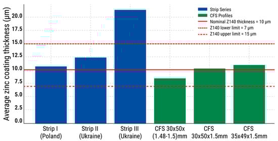
Figure 9.
Average zinc coating thickness for each tested series of specimens.
To visualize coating uniformity, Figure 10 shows the relative errors of each specimen series. The highest inhomogeneity was observed in CFS 30 × 50 × (1.48–1.5), with a relative error of 15.6%, while the most stable coating was achieved in Series II (4.4%). Higher values indicate potential risks to protective performance.
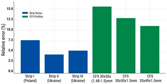
Figure 10.
Relative error (%) in zinc coating thickness for each specimen series.
Finally, a bubble chart (Figure 11) was used to compare the zinc coating thickness, variability, and uniformity simultaneously. The chart plots the average zinc coating thickness against the relative error, with the bubble size representing coating variance (S2). The CFS with dimensions 30 × 50 × (1.48–1.5) mm again stood out as the most vulnerable, exhibiting low average zinc coating thickness, high variability, and significant dispersion—a combination indicative of inconsistent coating quality.
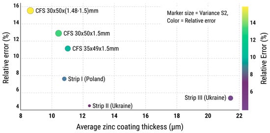
Figure 11.
Bubble chart showing correlation between average zinc coating thickness and relative error. Bubble size is proportional to variance (S2), reflecting the stability of the coating process elative error (%) in zinc coating thickness for each specimen series.
A boxplot diagram (Figure 12) was constructed to illustrate the zinc coating thickness for three strip specimens and three CFS specimens. Series I (10.8 ± 2.3 µm) and Series II (12.4 ± 1.5 µm) fully comply with the standard zinc coating thickness range of 7–15 µm. In contrast, Series III (21.4 ± 3.2 µm) exceeds the upper limit, indicating an excessive zinc coating thickness. The CFS series falls within the acceptable range. The lowest values were observed for CFS 30 × 50 × (1.48–1.5) mm—8.6 ± 3.7 µm—although none of the measurements dropped below 7 µm. The other series—CFS 30 × 50 × 1.5 mm (10.4 ± 3.7 µm) and CFS 35 × 49.5 × 1.5 mm (11 ± 3.4 µm)—also meet the standard, albeit with greater variation. Overall, all specimens except Series III comply with the normative requirements. The results indicate satisfactory coating quality with isolated deviations that require monitoring.
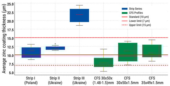
Figure 12.
Boxplot diagram of mean values and spread of zinc coating thickness for strip and CFS specimens.
Since the profiles were analyzed independently from the strip blanks, the reduction in zinc coating thickness is interpreted as a general trend rather than a direct measurement of losses on a single specimen.
3.4. Results of Chemical Analysis and Zinc Coating Mass Evaluation of the Specimens
A chemical analysis was carried out on 33 specimens using the procedure described in Section 2 (see Figure 7 and Figure 8). The aim of the analysis was to detect surface and subsurface contaminants that could contribute to the development of corrosion.
The initial step involved identifying the presence of chloride ions, which react with Ag+ cations to form a white AgCl precipitate, as shown in the reaction:
where AgCl is a characteristic white precipitate.
Cl− + Ag+ → AgCl↓
Chloride ions were detected on the surface of all 18 specimens taken from CFS, but were absent beneath the coating. None of the specimens cut from galvanized strip blanks showed the presence of chlorides.
Sulphate ions (SO42−) were identified using a classical reaction:
where BaSO4 is a white precipitate that is insoluble in HCl or H2SO4.
SO42− + Ba2+ → BaSO4↓
No sulphates were detected either on the surface or beneath the coating in any of the specimens, indicating effective rinsing following the pickling process.
Analysis for hexavalent chromium Cr(VI), used as an indicator of passivation, was carried out using a standard diphenylcarbazide-based chemical test. The specimens were dissolved in concentrated HNO3, followed by the addition of 1 mL of diluted H2SO4 (1:9 ratio), several drops of H3PO4, and 0.5 mL of a 0.5% diphenylcarbazide solution in acetone. After 10 min, the appearance of a reddish–violet coloration indicated a positive diphenylcarbazide response associated with Cr(VI)-related passivation products. In all 33 specimens (18 from CFS and 15 from strip blanks), a positive response was observed only after removal of the zinc coating, while no coloration was detected on the outer surface. It should be noted that this method provides an indicative qualitative assessment and does not allow unambiguous identification of chromium oxidation state distribution or depth profiling; such information requires surface-sensitive techniques such as XPS.
Iron oxides (FeO/Fe2O3), indicating residual scale, were identified beneath the zinc coating in all CFS specimens using an Olympus GX51 microscope, in accordance with ISO 8407:2021 and ISO 1463:2021. These oxides were not detected in the strip blanks, which indicates more effective pickling and surface cleaning during the production of the original galvanized coils.
The analysis of residual processing emulsions (“Universal–TS” or “Agrinol–HP”) was performed through sequential acid dissolution of 33 specimens weighing 2 g each in HNO3, followed by solvent extraction and paper chromatography. Trace amounts of organic substances were detected in all specimens.
The summarized results of the chemical analysis are presented in Table 7.
Table 7.
Results of chemical analysis of specimens from strip blanks and CFS (‘+’—detected; ‘–’—not detected; numerator—on surface, denominator—beneath zinc coating).
To quantitatively assess the mass loss of the zinc coating, a method based on EN 10346:2015 [22] was applied. This procedure involves dissolving the zinc coating in a 50% HCl solution containing 3.5 g/L of hexamethylenetetramine (urotropine) at room temperature (20–25 °C). A total of 12 specimens were selected (two from each specimen type), degreased with acetone, and weighed with an accuracy of 0.0001 g. They were then immersed in the solution until hydrogen evolution ceased, rinsed, dried at 100 °C, and reweighed. As a result, the coating mass amounted to 1.14–1.28% of the specimen mass in the strip blanks and 1.02% in the CFS, indicating partial zinc loss due to corrosion damage on the profiles prior to service.
Thus, the results of the study suggest that the corrosion of CFS has a complex origin, caused by the combined effect of technological factors (insufficient surface preparation of coils, presence of residual emulsions and iron oxides, lack of passivation on the external surface) and external influences (presence of atmospheric chlorides).
4. Discussion
The obtained results indicate that degradation of the zinc coating may begin as early as the coil (strip blank) manufacturing stage, well before the section forming process takes place. This is supported by the presence of five key defects, each with its own origin and potential contribution to reducing the durability of the final product. A schematic representation of zinc coating degradation by production stages is shown in Figure 13.
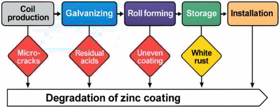
Figure 13.
Schematic representation of zinc coating degradation by production stages.
In particular, non-uniform zinc coating thickness across the strip width, especially in the edge zones, suggests possible disruptions in the cooling process or ineffective operation of the air knives. Local variations in zinc coating thickness may also lead to changes in the relative contribution of individual Zn–Fe sublayers, which differ in their electrochemical behavior and corrosion potential, thereby increasing susceptibility to localized corrosion, as discussed in [46]. These areas most frequently become sites of localized protection loss and corrosion initiation, indicating the need for localized monitoring or adjustments to the drying technology.
Mechanical damage reflects the influence of the rolling mill stands, which may result from uneven strip tension, roll contamination, or poor-quality lubrication. Such microcracks compromise the continuity of the zinc coating, creating conditions for moisture penetration and the formation of galvanic corrosion sites.
The presence of residual processing emulsions or contaminants on the zinc surface indicates violations in the rinsing regime after rolling or insufficient degreasing prior to coating application. Organic residues can significantly impair zinc adhesion to the base metal, potentially leading to zinc coating delamination under the influence of moisture and temperature.
A key conclusion is the absence of effective passivation on the external zinc surface, as confirmed by chemical analysis. An unprotected coating cannot withstand moisture exposure during transportation and storage; according to EN 10346:2015 [22] and EN 10143:2006 [47], at least passivation or a lubricating layer is required, and their absence constitutes a critical failure. The applied asymmetric passivation configuration does not ensure uniform chromate layer formation and prevents the development of a stable Cr(VI)-containing passivation film on the outer zinc surface. The detection of Cr(VI) only after dissolution of the zinc coating does not indicate selective passivation of a single strip side. Instead, it reflects the technological sequence of galvanized coil production, in which chromium-containing species may be introduced during strip preparation or auxiliary chemical treatments prior to zinc deposition. During hot-dip galvanizing, these compounds become trapped within the Zn–Fe interfacial region and are physically isolated from the external surface, remaining undetectable by surface-sensitive methods until the zinc layer is removed. Consequently, chromium-related compounds are detected only beneath the zinc coating, while the absence of Cr(VI) on the outer surface confirms that no effective final chromate-based passivation layer was formed on the external zinc surface.
Special attention should be given to surface non-uniformity, which indicates the presence of microdefects such as pores, inclusions, passivation stains, or poor alloying. These very defects later act as triggers for pitting corrosion and, from a quality control perspective, require analysis at the melt and recrystallization annealing stages.
Thus, the results of this research phase not only confirm the presence of critical defects but also clearly identify risk zones that require intervention at various stages of coil production. These findings will serve as a foundation for the subsequent analysis of the section condition after forming and storage.
The analysis of the roll-forming stage confirms that additional risk factors for the zinc coating arise during the shaping process itself, compounding the defects already identified at the coil steel manufacturing stage. Mechanical loading and deformation are well-known contributors to coating damage and loss of adhesion in engineering applications, particularly when combined with surface imperfections or residual stresses, as reported in failure analyses of coated systems [48]. Deformation- and contact-induced damage, zinc coating thickness reduction, and adverse storage conditions collectively contribute to the risk of early coating degradation.
Microcrack formation in bending zones is a well-known deformation-related phenomenon in galvanized steel sections and is generally associated with the limited ductility and brittle behavior of zinc coatings under mechanical loading. Experimental and numerical studies have demonstrated that zinc coatings tend to crack significantly earlier than the steel substrate and that the depth of such microcracks critically affects the degradation of protective and fatigue properties of coated steel products [49,50]. Such effects have been widely reported in the literature and may contribute to an increased susceptibility of the coating to friction-induced damage during roll forming. In the present study, microcracks were not directly identified in the examined specimens; therefore, this mechanism is discussed as a general technological consideration rather than an experimentally confirmed feature. Nevertheless, these considerations support the need to control minimum bending radii or to apply zinc-based coatings with enhanced ductility (e.g., ZnAlMg systems) in demanding forming conditions.
Contact-related defects caused by rollers are typical in production lines lacking automated pressure and roller condition control. The presence of such defects is further exacerbated when foreign particles-particularly abrasive debris or zinc residues-are present in the forming stands. This highlights the need to strengthen cleaning protocols for the forming rolls and to regularly inspect the condition of working surfaces.
The reduction in zinc coating thickness, particularly in comparison with the Z140 nominal specification, indicates that some section no longer complies with the EN10346:2015 standard. When the zinc coating thickness falls below 7–8 µm, its barrier performance declines significantly, and even minor surface damage may initiate corrosion.
The occurrence of “white rust” is a direct consequence of improper storage conditions, such as tight packaging, lack of ventilation, and high humidity.
As stated in EN 10143:2006, the manufacturer is responsible not only for the initial quality of the coating upon release, but also for its stability during transportation and temporary storage. In cases where sections have not yet developed a protective carbonate film (typically formed after passivation), the surface becomes particularly vulnerable.
Thus, corrosion damage on CFS is of a complex, multifactorial nature, which includes mechanical, chemical, and organizational causes. A similar multifactorial interpretation of coating degradation mechanisms, integrating technological, material-related, and organizational factors using quality management tools such as Ishikawa analysis, has been reported for galvanized steel systems in recent studies [51]. To improve the corrosion resistance of the products, integrated measures must be implemented, ranging from controlling bending radii and equipment cleanliness to optimizing packaging conditions and introducing mandatory passivation procedures. Further research should focus on modeling coating degradation under real-world storage and transportation conditions, as well as evaluating the performance of alternative coating systems.
The results of zinc coating thickness measurements provide a basis for several conclusions regarding the quality of the initial galvanized strip blanks, as well as the changes that occur during the cold-forming process. Overall, all specimens from the strip blanks demonstrate full compliance with the Z140 requirements of EN 10346:2015, with some even exceeding the typical zinc coating thickness of 10 µm. The highest value (21.4 µm) was recorded in a Ukrainian-made strip blank with a thickness of 1.5 mm. However, such an excess is not necessarily a positive indicator: excessive zinc coating thickness may lead to inefficient material use or impair dimensional accuracy during rolling.
As for the finished sections, two out of three series show average zinc coating thickness within the standard range. However, the CFS 30 × 50 × (1.48–1.5) mm specimen exhibited a critically low value of 8.6 µm, falling short of the typical Z140 level. Notably, this specimen also had the highest variance (S2 = 9) and the largest relative error (15.6%), indicating uneven and unstable coating distribution along the length or perimeter of the section.
A systematic comparison of the normative requirements of EN 10346 and EN 10143 with the actual test results is presented in Figure 14, allowing for visual identification of key non-conformities and their characteristics.
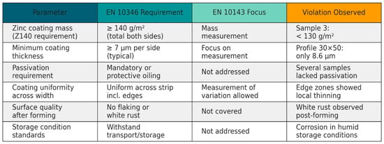
Figure 14.
Comparison of zinc coating compliance with the normative requirements of EN 10346 and EN 10143 standards.
A logical question arises regarding the cause of this reduction in zinc coating thickness: is it the result of an initial coating defect in the strip blank, or is it due to degradation of the zinc coating during the section forming process? Considering that other sections produced from similar material retained coatings within the standard range, it is more likely that mechanical abrasion or the formation of microcracks, caused by high deformation during bending, are responsible. It can also be assumed that the absence or imperfection of passivation in this surface area rendered the zinc coating less resistant to frictional stress.
An additional factor influencing corrosion behavior is the presence of residual moisture or lubricants between the steel substrate and the coating. According to the production technology, the strip must undergo degreasing, pickling, rinsing, and drying stages before galvanizing. Any violation of these steps, for instance, insufficient drying or residual acid film after pickling, reduces the adhesion of zinc to steel, manifesting as micro-delamination, pores, or the formation of “white rust” sites.
Logistical and storage issues also play a significant role. Corrosion traces were observed on the studied specimens even during the storage phase, prior to installation. This may indicate inadequate transportation conditions, such as tight packaging without air circulation, lack of tilt for moisture drainage (less than 5 mm/m), or exposure of the sections to moisture (rain, condensation) under poor ventilation. These factors are especially critical for freshly galvanized CFS that have not undergone sufficient passivation or were stored in humid environments.
Thus, the identified localized reduction in zinc coating thickness and early signs of corrosion point not only to flaws in the coating itself but also to insufficient integration between production, logistics, and installation processes. To ensure the durability and functionality of galvanized CFS, the following measures are necessary:
- Unification of zinc coating thickness standards for incoming inspection prior to roll forming;
- Enhanced control of lubrication and drying prior to galvanizing;
- Development of recommendations to minimize frictional abrasion during bending;
- Standardization of storage and transportation conditions, including tilt angle, ventilation, and humidity levels;
- Application of modern passivation methods for surface stabilization.
Overall, the conducted study revealed not only the general compliance of most specimens with the standard but also highlighted concerns about the reliability of the protective coating on the final product, particularly under conditions of technological or logistical irregularities. This calls for greater attention to establishing a systematic quality monitoring framework at all stages of production and delivery of galvanized CFS.
A summary of typical defects and recommended interventions is presented in Table 8.
Table 8.
Risk map and corresponding technological interventions.
The obtained results of chemical analysis provide several important insights into the origins and mechanisms of zinc coating degradation on CFS. In particular, the presence of chlorides exclusively on the CFS surface, combined with their absence in the original strip blanks, indicates an atmospheric origin of Cl− contaminants. Their deposition most likely occurred during transportation, storage, or the roll-forming process. Similar effects of surface chlorides and insufficient passivation on early zinc corrosion have been reported in recent studies [52,53]. Storage was performed during the winter period with snow and ice present, and the storage area was located near road infrastructure where de-icing mixtures containing chloride salts are commonly applied; under such conditions, chloride contamination may originate from snow, aerosols, and road-derived de-icing agents. The presence of chlorides is a critical factor in initiating corrosion, particularly the formation of “white rust” under conditions of elevated humidity.
The detection of Cr(VI) exclusively beneath the zinc coating in all specimens indicates selective passivation of the inner side of the strip prior to galvanizing. The absence of passivation on the outer surface creates additional vulnerability to the aggressive effects of chlorides, especially at sites of microdamage to the coating. This factor can be interpreted as a production error or a technological omission.
The presence of iron oxide residues on the sections, while being absent in the strip blanks, may indicate increased susceptibility of the zinc coating to local adhesion loss, potentially influenced by surface condition prior to galvanizing or by subsequent process-related effects. This underscores the importance of surface preparation control prior to galvanizing, particularly for reused or long-stored coils. The absence of iron oxide residues beneath the zinc coating in the strip blanks and their presence in the CFS do not constitute a contradiction but reflect different exposure histories. While the strip blanks represent the as-galvanized condition prior to forming and storage, the cold-formed sections were examined after both mechanical deformation and approximately two months of outdoor storage. Accordingly, the iron oxides detected in the CFS are attributed to the combined effects of local zinc coating discontinuities, deformation-induced damage, and post-forming atmospheric exposure, rather than to the initial CRC condition alone.
The detected organic residues (emulsions) in both strip blanks and sections are not necessarily a direct cause of corrosion; however, they may negatively affect zinc adhesion, particularly in cases of inadequate degreasing. These residues can also serve as sources of localized gas inclusions, which promote micropores and blisters in the coating, as shown in Table 9.
Table 9.
Comparison of detected defects across production and logistics stages.
To systematically understand the mechanisms of zinc coating degradation across all stages, from the production of coil stock to transportation and storage conditions, the main risk factors were summarized (see Table 9).
The cause-and-effect structure of these influences is presented in the form of an Ishikawa diagram (Figure 15), which covers six key categories: Equipment, Materials, Methods, Personnel, Measurements, and Environmental Conditions.
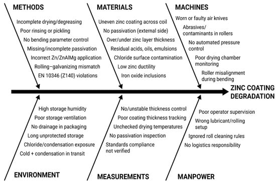
Figure 15.
Ishikawa cause-and-effect diagram for zinc coating degradation.
Additionally, to facilitate the analysis of damage types, a classification of influence types was developed based on their nature: mechanical, chemical, technological, and logistical (Figure 16). This allows for the identification not only of the sources but also of the nature of the critical defects observed in the studied specimens. Such an approach provides a foundation for developing a multi-level strategy to enhance coating durability.
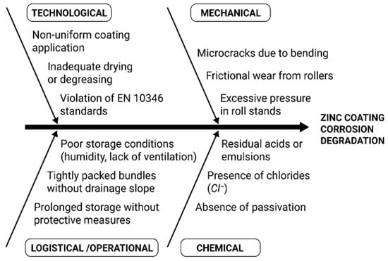
Figure 16.
Systematization of zinc coating impact factors by mechanisms of action.
Thus, the degradation of the coating on galvanized CFS is influenced by both external (atmospheric) factors and technological shortcomings occurring throughout the entire production chain from pickling to passivation and roll forming. The conclusions obtained provide a foundation for further analysis of the microstructural features within the damage zones and for assessing the impact of different storage conditions.
5. Conclusions
The relevance of this study is driven by the increasing incidence of premature zinc coating degradation in galvanized CFS under real production, transportation, and storage conditions, which directly results in product rejections, customer claims, and additional costs for industrial enterprises. Therefore, identifying quantitative indicators of coating instability and mapping them to actionable technological and logistical measures is critical for improving the reliability and corrosion resistance of CFS in industrial practice. The results obtained in this work can be summarized in the following conclusions:
- The degradation of zinc coating on galvanized CFS has been shown to exhibit a complex nature, driven by the combined effects of technological and atmospheric factors, such as the following: presence of residual emulsions and iron oxides on the surface of the strip blanks; absence of passivation on the outer surface in 100% of analyzed specimens (Cr(VI) was detected only beneath the coating); non-uniform zinc coating thickness across the width of the strip, particularly in the edge zones.
- The average zinc coating thickness on most sections was measured to meet the Z140 standard requirements (10 µm as per EN 10346:2015). However, one specimen (30 × 50 × 1.48–1.5 mm) showed a critically low average zinc coating thickness of 8.6 µm, with a relative error of 15.6% and the highest variance (S2 = 9), indicating instability of the protective zinc coating.
- From a quantitative standpoint, the obtained results indicate that the risk of zinc coating degradation increases markedly when the average zinc coating thickness decreases below 10 µm and becomes critical at values around 8.6 µm. Elevated thickness variance (S2) and relative deviations above 15% may therefore be considered practical indicators for identifying high-risk production batches during quality control of galvanized coils and CFS.
- Chemical analysis revealed the presence of atmospheric-origin chlorides only on the surface of finished sections (in 100% of specimens), highlighting the influence of transportation and storage conditions. At the same time, iron oxides and emulsion residues were found exclusively in finished sections but not in strip blanks, confirming the impact of frictional and thermal processes in the bending zone. It should be emphasized that the iron oxide residues beneath the zinc coating were observed exclusively in CFS after roll forming and outdoor storage, whereas the strip blanks represented the as-galvanized reference condition. This observation is consistent with the iron oxides being related to post-forming deformation effects and subsequent atmospheric exposure during storage, rather than being solely determined by the initial condition of the galvanized steel strip.
- The scientific novelty of this study lies in the quantitative establishment of the correlation between localized technological deviations (such as pickling, passivation, and rolling) and the occurrence of corrosion phenomena, particularly “white rust”, in sections made from DX51D+Z140 steel. For the first time, it has been demonstrated that general compliance with Z140 standards does not guarantee long-term durability if micro-conditions during coating application, passivation, and storage are not properly maintained.
- The practical significance of this work lies in the development of a risk map and the identification of critical production stages that require urgent improvement. The proposed recommendations include technological, logistical, and organizational measures, such as the implementation of automated bend radius control, the use of alternative coating alloys (e.g., ZnAlMg), standardization of ventilation during packaging, and the unification of passivation requirements.
- The prospects for further research involve modeling zinc coating degradation processes under variable climate conditions, optimizing the composition of multi-component coatings for hot-dip galvanizing (including ZnAl, ZnMg, ZnAlMg) to improve the plasticity of the zinc coating, and developing automated methods for monitoring of zinc coating thickness and uniformity at the coil production stage prior to roll forming.
Author Contributions
Conceptualization, V.K. (Volodymyr Kukhar), A.K. and O.H.; Methodology, V.K. (Volodymyr Kukhar), A.K., O.S. and S.M.; Validation, V.K. (Volodymyr Kukhar), A.K., I.K., R.V., E.B., O.S. and S.M.; Formal analysis, V.K. (Volodymyr Kukhar), A.K., R.V., N.H. and O.H.; Investigation, O.D., O.M., I.K., V.K. (Viktoriia Kulynych), K.M., E.B., O.S. and O.H.; Resources, O.D., O.M., E.B. and S.M.; Data curation, O.D., R.V., V.K. (Viktoriia Kulynych), N.H. and O.H.; Writing—original draft, O.D. and V.K. (Viktoriia Kulynych); Writing—review & editing, V.K. (Volodymyr Kukhar), A.K., K.M. and N.H.; Visualization, O.M., I.K., K.M. and O.H.; Supervision, V.K. (Volodymyr Kukhar) and O.H.; Project administration, V.K. (Volodymyr Kukhar); Funding acquisition, V.K. (Volodymyr Kukhar), A.K. and O.H. All authors have read and agreed to the published version of the manuscript.
Funding
This research received no external funding.
Data Availability Statement
The original contributions presented in this study are included in the article. Further inquiries can be directed to the corresponding authors.
Conflicts of Interest
Authors Volodymyr Kukhar and Natalia Hrudkina were employed by Technical University “Metinvest Polytechnic” LLC. The remaining authors declare that the research was conducted in the absence of any commercial or financial relationships that could be construed as a potential conflict of interest.
Abbreviations
The following abbreviations are used in this manuscript:
| CFS | Cold-formed sections |
| CGL | Continuous Galvanizing Line |
| CRC | Cold-rolled coils |
| CS | Crop shear |
| CTL/SL | Cut-to-length and slitting lines |
| GDP | Gross Domestic Product |
| HRC | Hot-rolled coils |
| HRM | Hot rolling mills |
| PID | Proportional–Integral–Derivative controller (temperature control unit in industrial processes) |
| TLC | Thin Layer Chromatography |
References
- Teremetskyi, V.; Avramova, O.; Maikut, K.; Tserkovna, O.; Kramar, R. Current situation and transformation ways of housing policy in Ukraine. Soc. Leg. Studios 2024, 7, 164–173. [Google Scholar] [CrossRef]
- Thirunavukkarasu, K.; Kanthasamy, E.; Gatheeshgar, P.; Poologanathan, K.; Rajanayagam, H.; Suntharalingam, T.; Dissanayake, M. Sustainable performance of a modular building system made of built-up cold-formed steel beams. Buildings 2021, 11, 460. [Google Scholar] [CrossRef]
- Kowalczyk, Z.; Twardowski, S.; Malinowski, M.; Kuboń, M. Life cycle assessment (LCA) and energy assessment of the production and use of windows in residential buildings. Sci. Rep. 2023, 13, 19752. [Google Scholar] [CrossRef] [PubMed]
- Tharmarajah, G.; Van Doren, K. Cold formed steel for residential construction—Design philosophy and durability assessment. Preprints 2023, 2023090106. [Google Scholar] [CrossRef]
- Francis, R. What do you know about inorganic zinc coatings? Mater. Perform. 2016, 55, 40–43. [Google Scholar] [CrossRef]
- Terrados-Cristos, M.; Ortega-Fernández, F.; Alonso-Iglesias, G.; Díaz-Piloneta, M.; Fernández-Iglesias, A. Corrosion prediction of weathered galvanised structures using machine learning techniques. Materials 2021, 14, 3906. [Google Scholar] [CrossRef]
- Hays, G.F. Now Is the Time; World Corrosion Organization: New York, NY, USA, 2010; Available online: https://corrosion.org/Corrosion%20Resources/Publications/_/nowisthetime.pdf (accessed on 19 November 2025).
- Chico, B.; De la Fuente, D.; Díaz, I.; Simancas, J.; Morcillo, M. Annual atmospheric corrosion of carbon steel worldwide. An integration of ISOCORRAG, ICP/UNECE and MICAT databases. Materials 2017, 10, 601. [Google Scholar] [CrossRef]
- Kusmierek, E.; Chrzescijanska, E. Atmospheric corrosion of metals in industrial city environment. Data Brief 2015, 3, 149–154. [Google Scholar] [CrossRef] [PubMed]
- Kukhar, V.; Balalayeva, E.; Hurkovska, S.; Sahirov, Y.; Markov, O.; Prysiazhnyi, A.; Anishchenko, O. The Selection of Options for Closed-Die Forging of Complex Parts Using Computer Simulation by the Criteria of Material Savings and Minimum Forging Force. Adv. Intell. Syst. Comput. 2020, 989, 325–331. [Google Scholar] [CrossRef]
- Deyá, C.; Carrizo, P.S. Corrosion on ancient metals. In Reverse Engineering of Ancient Metals; Carrizo, P.S., Ed.; Springer: Cham, Switzerland, 2022; pp. 123–146. [Google Scholar] [CrossRef]
- Pinto, G.; Silva, F.J.G.; Baptista, A.; Campilho, R.D.S.G.; Viana, F. Investigations on the oxidation of Zn-coated steel cables. FME Trans. 2021, 49, 587–597. [Google Scholar] [CrossRef]
- Cai, Y.; Zhao, Y.; Ma, X.; Zhou, K.; Chen, Y. Influence of environmental factors on atmospheric corrosion in dynamic environment. Corros. Sci. 2018, 137, 163–175. [Google Scholar] [CrossRef]
- Tamimi, M.F.; Alshannaq, A.A.; AbuQamar, M.I. Deterioration of steel structures due to corrosion considering the global effects of climate change. Corros. Eng. Sci. Technol. 2024, 59, 273–293. [Google Scholar] [CrossRef]
- Nguyen, M.N.; Wang, X.; Leicester, R.H. An assessment of climate change effects on atmospheric corrosion rates of steel structures. Corros. Eng. Sci. Technol. 2013, 48, 359–369. [Google Scholar] [CrossRef]
- Cicek, V.; Al-Numan, B. Corrosion Chemistry; Scrivener Publishing LLC: Beverly, MA, USA, 2011. [Google Scholar] [CrossRef]
- Chernenko, S.; Klimov, E.; Chernish, A.; Pavlenko, O.; Kukhar, V. Simulation technique of kinematic processes in the vehicle steering linkage. Int. J. Eng. Technol. (UAE) 2018, 7, 120–124. [Google Scholar] [CrossRef]
- Shatskyi, I.P.; Makoviichuk, M.V.; Shcherbii, A.B. Equilibrium of cracked shell with flexible coating. In Shell Structures: Theory and Applications 4; CRC Press: Boca Raton, FL, USA, 2018; pp. 165–168. [Google Scholar] [CrossRef]
- Shats’kyi, I.P.; Makoviichuk, M.V. Contact interaction of crack lips in shallow shells in bending with tension. Mater. Sci. 2005, 41, 486–494. [Google Scholar] [CrossRef]
- Anđelić, N.M.; Milošević-Mitić, V.O.; Petrović, A.S. Stress constraints applied to the optimization of a thin-walled Z-beam. FME Trans. 2014, 42, 237–242. [Google Scholar] [CrossRef]
- Hussein, D.B.; Hussein, A.B. Investigating the factors influencing the strength of cold-formed steel (CFS) sections. Buildings 2024, 14, 1127. [Google Scholar] [CrossRef]
- EN 10346:2015; Continuously Hot-Dip Coated Steel Flat Products for Cold Forming—Technical Delivery Conditions. European Committee for Standardization (CEN): Brussels, Belgium, 2015.
- Artiukh, V.; Mazur, V.; Kukhar, V.; Vershinin, V.; Shulzhenko, N. Study of polymer adhesion to steel. E3S Web Conf. 2019, 110, 01048. [Google Scholar] [CrossRef]
- Kalisz, D.; Żak, P.L.; Semiryagin, S.; Gerasin, S. Evolution of chemical composition and modeling of growth nonmetallic inclusions in steel containing yttrium. Materials 2021, 14, 7113. [Google Scholar] [CrossRef] [PubMed]
- Efremenko, V.G.; Lekatou, A.G.; Chabak, Y.G.; Efremenko, B.V.; Petryshynets, I.; Zurnadzhy, V.I.; Emmanouilidou, S.; Vojtko, M. Micromechanical, corrosion and wet sliding wear behaviours of Co-28Cr-6Mo alloy: Wrought vs. LPBF. Mater. Today Commun. 2023, 36, 105936. [Google Scholar] [CrossRef]
- Efremenko, B.V.; Shimizu, K.; Espallargàs, N.; Efremenko, V.G.; Kusumoto, K.; Chabak, Y.G.; Belik, A.G.; Chigarev, V.V.; Zurnadzhy, V.I. High-temperature solid particle erosion of Cr–Ni–Fe–C arc cladded coatings. Wear 2020, 460–461, 203439. [Google Scholar] [CrossRef]
- Mukhopadhyay, A.; Sahoo, S. Corrosion performance of steel rebars by application of electroless Ni-P-W coating—An optimization approach using grey relational analysis. FME Trans. 2021, 49, 445–455. [Google Scholar] [CrossRef]
- Kukhar, V.; Klimov, E.; Chernenko, S. Analysis of galvanized steel sheets fabrication in cold rolling shop and identification of local impacts contributing to corrosion of metal-products. Solid State Phenom. 2021, 316, 873–879. [Google Scholar] [CrossRef]
- Kurpe, O.H.; Kukhar, V.V.; Klimov, E.S.; Chernenko, S.M. Improvement of process parameters calculation for coil rolling at the Steckel mill. Mater. Sci. Forum 2020, 989, 609–615. [Google Scholar] [CrossRef]
- Kurpe, O.; Kukhar, V.; Klimov, E.; Prysiazhnyi, A. Thermomechanical controlled rolling of hot coils of steel grade S355MC at the wide-strip rolling mill 1700. Solid State Phenom. 2019, 291, 63–70. [Google Scholar] [CrossRef]
- Kukhar, V.V.; Kurpe, O.H.; Prysiazhnyi, A.H.; Khliestova, O.A.; Burko, V.A.; Balalayeva, E.Y.; Yelistratova, N.Y. Improving of preventive management for flat rolling products quality indices. IOP Conf. Ser. Mater. Sci. Eng. 2021, 1037, 012024. [Google Scholar] [CrossRef]
- Anishchenko, A.; Kukhar, V.; Artiukh, V.; Arkhipova, O. Application of G. Lame’s and J. Gielis’ formulas for description of shells superplastic forming. MATEC Web Conf. 2018, 239, 06007. [Google Scholar] [CrossRef]
- Akobirova, L.; Gafurov, K.; Jumayev, J.; Kuldasheva, F.; Xikmatov, D. Experimental study of crushing process of the crushed stone. E3S Web Conf. 2021, 264, 04093. [Google Scholar] [CrossRef]
- Achkan, V.V.; Vlasenko, K.V.; Chumak, O.O.; Sitak, I.V.; Kovalenko, D.A. A model of learning the online course “Creative Thinking through Learning Elementary Maths”. J. Phys. Conf. Ser. 2022, 2288, 012020. [Google Scholar] [CrossRef]
- Hrudkina, N.S.; Markov, O.E.; Shapoval, A.A.; Titov, V.A.; Aliiev, I.S.; Abhari, P.; Malii, K.V. Mathematical and computer simulation for the appearance of dimple defect by cold combined extrusion. FME Trans. 2022, 50, 90–98. [Google Scholar] [CrossRef]
- Aliieva, L.I.; Markov, O.E.; Aliiev, I.S.; Hrudkina, N.S.; Levchenko, V.N.; Malii, K.V. Analysis of power parameters of combined three-direction deformation of parts with flange. FME Trans. 2021, 49, 344–355. [Google Scholar] [CrossRef]
- Sikulskiy, V.; Kashcheyeva, V.; Romanenkov, Y.; Shapoval, A. Study of the process of shape-formation of ribbed double-curvature panels by local deforming. East.-Eur. J. Enterp. Technol. 2017, 4, 43–49. [Google Scholar] [CrossRef]
- Drahobetsky, V.V.; Shapoval, A.A.; Shchetynin, V.T.; Argat, R.G.; Shlyk, S.V.; Mos’pan, D.V.; Gorbatyuk, S.M.; Markov, O.E. New solution for plastic deformation process intensification. Metallurgist 2022, 65, 1108–1116. [Google Scholar] [CrossRef]
- Khrebtova, O.; Shapoval, O.; Markov, O.; Kukhar, V.; Hrudkina, N.; Rudych, M. Control systems for the temperature field during drawing, taking into account the dynamic modes of the technological installation. In Proceedings of the 2022 IEEE 4th International Conference on Modern Electrical and Energy System (MEES), Kremenchuk, Ukraine, 20–23 October 2022; pp. 1–6. [Google Scholar] [CrossRef]
- Zhang, D. Strip Cold Rolling. In The ECPH Encyclopedia of Mining and Metallurgy; Kuangdi, X., Ed.; Springer: Singapore, 2024; pp. 2064–2067. [Google Scholar] [CrossRef]
- Schlegel, J. Manufacturing Processes. In The World of Steel; Springer: Wiesbaden, Germany, 2023; pp. 297–355. [Google Scholar] [CrossRef]
- Rasulova, M.K. Mathematical analysis of the dependence of the optimization parameter on the factors affecting the strength of the thread connection of workwear parts. Ilkogretim Online 2021, 20, 786. [Google Scholar] [CrossRef]
- ISO 8407:2021; Corrosion of Metals and Alloys—Removal of Corrosion Products from Corrosion Test Specimens. International Organization for Standardization (ISO): Geneva, Switzerland, 2021.
- ISO 1463-2021; Metallic and Oxide Coatings—Measurement of Coating Thickness—Microscopical Method. International Organization for Standardization: Geneva, Switzerland, 2021.
- ISO 1460-2020; Metallic Coatings—Hot Dip Galvanized Coatings on Ferrous Materials—Gravimetric Determination of the Mass per Unit Area. International Organization for Standardization: Geneva, Switzerland, 2020.
- Li, Z.; Li, D.; Zhou, Y.; Peng, H.; Xie, A.; Wang, J. A review of physical properties of hot-dip galvanized coating layer by layer and their respective electrochemical corrosion behavior. Anti-Corros. Methods Mater. 2024, 71, 580–589. [Google Scholar] [CrossRef]
- EN 10143-2006; Continuously Hot-Dip Coated Steel Sheet and Strip—Tolerances on Dimensions and Shape. European Committee for Standardization: Brussels, Belgium, 2006.
- Buchman, A. Failure cases in adhesive joints and coatings. In Progress in Adhesion and Adhesives; Mittal, K.L., Ed.; Wiley: Hoboken, NJ, USA, 2025; Volume 9. [Google Scholar] [CrossRef]
- Nakagawa, K.; Nakagaito, T.; Nakajima, S.; Nagoshi, M.; Tamai, Y.; Hiramoto, J.; Yoshitake, A. Effect of micro-crack depth on fatigue property in Zn–Ni coated press hardened steel. Mater. Trans. 2023, 64, 2270–2277. [Google Scholar] [CrossRef]
- Huang, F.; Liu, Y.; Tao, X.; Wang, H.; Wang, J.; Zhang, D. Cracking behavior of zinc coating on pre-cracked hot-dip galvanized steel plate under static tension. Structures 2024, 61, 106019. [Google Scholar] [CrossRef]
- Kurc-Lisiecka, A.; Lisiecki, A. Quality assessment and analysis of the causes of coating defects in the powder coating process. Int. J. Mod. Manuf. Technol. 2025, XVII, 7–17. [Google Scholar] [CrossRef]
- Wang, J. Advances in the understanding of corrosion and performance of hot-dip galvanized rebar in concrete structures. Corros. Rev. 2025. [Google Scholar] [CrossRef]
- Pokorný, P.; Kouřil, M. Predicted Corrosion Performance of Organofunctional Silane Coated Steel Reinforcement for Concrete Structures: An Overview. Buildings 2024, 14, 1756. [Google Scholar] [CrossRef]
Disclaimer/Publisher’s Note: The statements, opinions and data contained in all publications are solely those of the individual author(s) and contributor(s) and not of MDPI and/or the editor(s). MDPI and/or the editor(s) disclaim responsibility for any injury to people or property resulting from any ideas, methods, instructions or products referred to in the content. |
© 2026 by the authors. Licensee MDPI, Basel, Switzerland. This article is an open access article distributed under the terms and conditions of the Creative Commons Attribution (CC BY) license.