Abstract
The aluminum casting alloy AlSi7Mg0.6 (A357) is extensively used in the automotive industry due to its favorable balance of mechanical properties, castability, lightweight characteristics, and corrosion resistance. Castings made from this alloy are often subjected to harsh service environments, where surface degradation and microstructural variability can significantly impact fatigue performance. This study investigates the combined effects of surface corrosion damage and higher Fe content on the fatigue life of the AlSi7Mg0.6 alloy, using a rotating bending fatigue test under simultaneous corrosion exposure in a 3.5 wt. % NaCl solution. The effect of corrosion and Fe content on fatigue life was then investigated and analyzed using Wöhler curves and scanning electron microscopy (SEM). The results demonstrate that the corrosion-fatigue interaction accelerated the kinetics of the fatigue process, while the fracture mechanism and crack initiation places are not fundamentally altered compared to alloys in the state without corrosion damage. A comparison of the fatigue lifetime of samples in an air environment and a corrosive environment shows that the corrosive environment (3.5% NaCl) reduces the fatigue lifetime of alloys without T6 by an average of 7.5 MPa and alloys after T6 by 6 MPa. The results are probably due to the penetration of chloride ions into casting defects located on the surface of the samples. Surface pits formed during corrosion act as stress concentrators, increasing the likelihood of stress-induced failure. Microstructural feature morphology, especially Fe-rich intermetallic phases, influences crack propagation mechanisms.
1. Introduction
Manufacturing has become a major focus of research and innovation, especially with the increasing environmental regulations. Lightweight materials also have a major focus in electric vehicles due to their numerous advantages. With the growing demand for lightweight construction, aluminum cast alloys have emerged as an ideal choice for energy-efficient and cost-effective components due to their excellent strength-to-weight ratio and low cost. The rapid growth of the electric vehicle market has placed electric vehicle manufacturing companies under significant pressure to secure essential raw materials while ensuring environmental sustainability and cost-effectiveness. One of the most effective strategies to address these challenges is the use of lightweight materials, which can significantly enhance the performance and efficiency of electric vehicles. It is well known that the use of Al can reduce weight by 25–65% compared to steel [,,,,].
The most commonly used cast alloys in foundries are alloys based on Al-Si. One of the key advantages of these alloys is their undemanding recyclability. Other advantages of Al-Si alloys are good weldability, corrosion resistance, and low solidification shrinkage levels. Aluminum alloy scrap has a lower melting temperature and shorter melting time, which means using secondary aluminum can lead to energy savings (uses 5% of energy compared to the conventional manufacturing of bulk aluminum from bauxite), reducing fuel consumption (with 85% less CO2 emissions). Recycling of aluminum only emits 5% greenhouse gas, and minimizes the use of chemicals compared to primary aluminum production. It is a great environmental benefit. Currently, approximately 70% of recycled aluminum is primarily used in the production of aluminum–silicon casting alloys, which are predominantly used in the automotive industry. The remaining portion is converted into wrought alloys for reuse in sheet or extruded forms, with a small fraction being transformed into de-oxidants for the steel industry. The main problem is the presence of higher Fe content in secondary alloys, but for the automotive industry it is acceptable [,,]. Impurity levels above 0.10–0.15 wt. % Fe are not acceptable for some aerospace components, but they are acceptable for the automotive industry. The addition of Cu, Mg, Fe, Mn, Si, and other elements to aluminum results in the formation of intermetallic phases, which makes it more susceptible to corrosion attacks in corrosive environments [,,,]. This is caused by the fact that an intermetallic phase is a metallic phase consisting of two or more metallic elements with a unique crystalline structure []. The presence of brittle Fe-rich intermetallic phases (Al5FeSi) negatively affects the fatigue life of aluminum alloys, but also the corrosion resistance [,]. Al5FeSi is cathodic with respect to the aluminum matrix and can be the root cause of localized pitting corrosion in Al-Mg-Si []. In addition to the corrosion resistance, the Al5FeSi phase also harms mechanical properties (decrease in ductility and ultimate tensile strength). The plate-like Al5FeSi phase can also influence porosity, which has a negative effect on fatigue, mechanical, and corrosion properties [,,,,].
The Mg in Al-Si-Mg cast alloy ensures excellent casting properties, along with great mechanical properties after heat treatment, as well as elevated corrosion resistance and low thermal expansion []. The main application of Al-Si-Mg aluminum cast requires excellent mechanical and fatigue properties. The simultaneous action of cyclic mechanical loading and corrosive environmental exposure during service can significantly accelerate the initiation of fatigue cracks, leading to premature structural failure. Consequently, corrosion fatigue represents a critical concern for the application of aluminum alloys in transportation systems operating in marine environments or in regions where de-icing salts are employed during winter conditions []. Also, the heterogeneous microstructures of aluminum alloy components make them particularly prone to corrosion-related degradation. The presence of high concentrations of chloride ions lead to the formation of pitting corrosion []. A corrosive attack can significantly compromise structural integrity, as fatigue cracks may initiate at corrosion-induced surface pits and subsequently propagate at an accelerated rate under corrosive environmental conditions. Moreover, corrosion represents a considerable economic challenge, as inspection, maintenance, and repair activities required to mitigate its effects are both resource-intensive and costly. Consequently, there is a need for a comprehensive assessment of corrosion–fatigue interactions to ensure the continued structural reliability and cost-effective operation of aluminum alloy castings [,,]. Thanks to a great affinity of aluminum and its alloys for oxygen, the formation of a passive layer of Al2O3 on the surface is common only in the atmosphere. The oxide layer protects the material against the continuation of the corrosion process. The thickness of the protective oxide film is about 5 nm. The layer is resistant to attack from water and oxygen in a wide range of temperatures. The most widely used corrosive environment in vehicle components, besides the atmosphere, is the presence of deicing salts, chemicals sprayed on roads in winter. The corrosion behavior of aluminum alloys in these environments is not as good as in the atmosphere (aluminum alloys are attacked by localized forms of corrosion), and it still needs to be investigated [,].
Current fatigue research focuses on characterizing fatigue failure of materials in two forms [,,]:
- the stress–life (S-N) curve representing the fatigue behavior of smooth or unnotched specimens, also called the Wöhler curves;
- the fatigue crack growth (FCG) curve capturing the growth characteristics of a crack through the material.
Fatigue life data are usually presented in the form of an S-N curve from the data generated by testing a large number of samples with at least one tested at each cyclic stress, which ranges from the endurance stress limit to the tensile strength limit [,,]. The fatigue strength is called the fatigue limit (or endurance limit) when the number of cycles reached has exceeded the number of cycles the material is expected to withstand in its lifetime []. Fatigue strengths are frequently used to determine safe loading limits for specific materials, designs, and loading configurations. It is also the standard form by which assessments are made of the effects of metallurgical processing and microstructure, or the environmental effects due to corrosion and temperature, or the state of the material as affected by internal (residual) stress and surface condition, etc. The S-N dataset also forms the basis for determining the safe cyclic stresses that could be allowed in mechanical designs [,,].
The present study aims to investigate the combined effect of microstructural heterogeneity, cyclic load, 3.5% NaCl environment, and heat treatment on the fatigue life of secondary AlSi7Mg0.6 cast alloys.
2. Materials and Methods
In real-world service conditions, components are frequently subjected to both cyclic loading and corrosive environments, which can significantly degrade fatigue performance. The technical application of experimental materials [,] must also exhibit excellent fatigue properties under corrosive conditions.
2.1. Experimental Material
The experimental work was focused on secondary AlSi7Mg0.6 (AC 42 200, A357) cast alloys. It is currently the most widely used alloy for castings in the automotive industry, aerospace industry, and additive manufacturing (engine blocks and cylinder heads, transmission housings, gearbox casings, suspension components, brake calipers, electric vehicle motor housings, and battery trays). Products made from secondary Al alloys must maintain high quality and consistent, comparable properties throughout their entire service life to compete with primary Al alloys. The quality of the casting itself is influenced by several factors, one of which is the presence of Fe, which is usually higher in secondary Al alloys. Removing Fe from Al scrap is a costly process; therefore, it is necessary to study its effects on the properties of the alloy and to establish the maximum limit of the amount of iron that is least harmful to the service life of the product, and is therefore acceptable. In the primary Al alloy, Fe is a natural impurity with a content of 0.02 wt. % to 0.15 wt. %. These percentages depend on the quality of the primary ore. From this point of view, various sets of AlSi7Mg0.6 alloys were cast in cooperation with Uneko Ltd., Zátor, Czech Republic (Figure 1, Table 1).
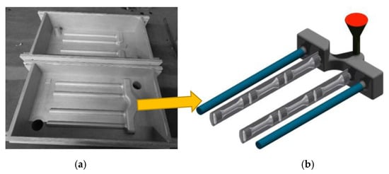
Figure 1.
Casting of experimental sets (a) casting mold; (b) model of final casting.

Table 1.
The chemical composition of experimental casting melts in wt. %.
The aluminum scrap used for recycling includes old scrap and new scrap derived from production waste, such as machining swarf and post-consumer scraps. Whereas aluminum casting companies are currently wary of producing castings in this way, the main task was to control the contamination of primary alloys with iron. In Uneko, Fe values were determined based on the observance of appropriate melting conditions and casting quality (Table 1). At increased Fe contents above 0.4 wt. %, Mn was also added to the last casting sets. The content of Mn In the Melt 4 was adjusted by the casting company Uneko to ensure a good casting quality. The primary objective was to optimize the casting process itself, rather than to maintain the Fe/Mn ratio required for achieving specific mechanical properties or affecting the morphology of intermetallic phases. The amount of Mn (Table 1) was not sufficient, because it did not meet the ratio condition of Fe/Mn (0.5), so the formation of acicular Fe phases is not affected. Maintaining the Fe/Mn ratio is required to achieve a beneficial size, morphology, and distribution of the intermetallic phases, enhancing the structural and functional properties of casting []. The casting sets were marked according to Fe content:
- AC = Melt 1: as-cast state, content of Fe = 0.128 wt. %, without addition of Mn;
- 2Fe = Melt 2: increasing content of Fe = 0.202 wt. %, without addition of Mn;
- 3Fe = Melt 3: increasing content of Fe = 0.429 wt. %, without addition of Mn;
- 3Fe + Mn = Melt 4: increasing content of Fe = 0.429 wt. %, with addition of Mn = 0.149 wt. %;
Test bars ø 20 × 300 mm (Figure 1b) were cast from individual experimental melts into a sand mold using gravity casting (Figure 1b). The casting temperature was 750 °C, and the refining temperature was 740–745 °C. ECOSAL AL 113S salt was used as the refining salt. A total of 72 test bars were cast from each casting set (melt). Heat treatment (T6) was applied to half of the test bars (i.e., 36 bars). The heat treatment designated as T6 was carried out in UNEKO, Ltd., according to the standards for AlSi7Mg0.6 cast alloy. Heat treatment consisted of solution treatment at a temperature of 530 °C ± 5 °C with a holding time of 7 h, rapid cooling to a water temperature of 50 °C, and subsequent artificial aging at a temperature of 160 °C for 6 h.
2.2. Experimental Measurements
2.2.1. Microstructure Evaluation
The microstructural characterization of experimental materials is a fundamental aspect of materials science and can be performed using various methods of quantitative metallography. Historically, microstructure evaluation relied on reference standards (etalons), manual measurements using test grids, and other conventional techniques. However, with advances in digital imaging and computational tools, automated image analysis has become the predominant method []. Therefore, the image analysis software NIS Elements 5.0 was used for the evaluation of the size, volume, and shape of Fe-rich phases and porosity in experimental casting melts. The samples for analysis were prepared from the tensile test specimens after testing by standard metallography methods and etched by 0.5% HF. The 3D morphology of microstructural features was evaluated on a scanning electron microscope (Tescan, Vega LMU II, Brno, Czech republic) by etching with HCl. The scanning electron microscope was also used for fractography analysis of the tested specimens.
The Al5FeSi phase has a monoclinic crystal lattice with a plate-like morphology [,]. The plate-like (needle-like) morphology increases stress potential and acts as a stress concentrator, which contributes to the brittleness of Al-alloys [,]. The longer needles of the Al5FeSi phase limit solidification and are considered to be active pore initiators and contribute to their growth. Current knowledge shows that crystallization of β Fe-phases can be minimized in foundry alloys by increasing the cooling rate, adding appropriate additive elements to promote the formation of other phases with less harmful morphology (most often Mn), increasing the Si content (Table 2), heat treatment, or overheating the melt [,]. Increasing Si content increases the amount of iron that can be tolerated from the point of view of crystallization of β-phases in Al-Si alloys [,]. The critical value is calculated according to (1):
Fecrit. = 0.075 × (% Si) – 0.05

Table 2.
The critical iron content in Al-Si alloys [].
Other works [,] have also demonstrated the effect of adding various additive elements such as Mn, Cr, Co, Nb, Be, Ni, V, Mo, or K, in combination with high cooling rates, to suppress the formation of β-platelet Fe phases.
2.2.2. Mechanical Properties
Test specimens were prepared with dimensions conforming to the ISO 6892-1:2009 standard for the measurement of ultimate tensile strength (UTS—Figure 2a). From one cast road, three tensile specimens (Figure 1b) were made.
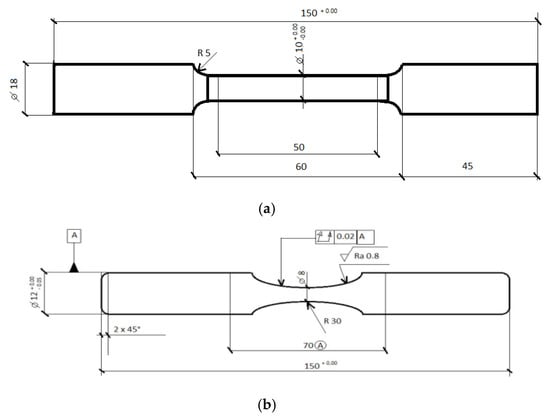
Figure 2.
Dimensions of (a) a tensile specimen for mechanical tests, and (b) a test bars for fatigue tests.
Changes in tensile properties, specifically UTS, yield strength (YS), and ductility, were evaluated using an INSTRON Model 5985 universal testing machine (Instron, Norwood, MA, USA) in accordance with ISO 6892-1:2019 []. Test rates and control settings were selected based on the recommended ranges of Method A, which is suitable for materials exhibiting a clearly defined linear elastic region and homogeneous deformation behavior. The obtained results include UTS, YS, and ductility.
Hardness measurements of the secondary aluminum alloy were performed using a Brinell hardness tester CV 3000 LDB (NT-new technologies, Prague, Czech Republic), applying a load of 250 kp (1 kp = 9.80665 N), with a 5 mm diameter steel ball and a dwell time of 10 s.
All reported values of UTS, YS, ductility, and Brinell hardness represent the average of at least six independent measurements for each experimental material.
2.2.3. Fatigue Properties
Two test specimens for fatigue tests (Figure 2b—20 bars from each heat) were machined from one cast bar (Figure 1b). The shape and dimensions of the test specimen for rotational bending fatigue tests are documented in Figure 2b. The total length of the samples was 150 mm. The sample thickness in the fatigue region was 8 mm. Fatigue tests were performed on a KAUP rotating machine operating in the loading mode, bending during rotation, at the Department of Materials Engineering, Faculty of Mechanical Engineering, University of Žilina, Žilina, at ambient temperature (20 °C ± 5 °C). The KAUP machine used a frequency of 32.1 Hz, and the selected load had an alternating symmetrical (tension–compression) sinusoidal character (R = −1). From each melt, 6 to 10 test specimens were selected; measurements were performed under the same conditions, at defined stress amplitude values of 68, 78, and 87 MPa.
2.2.4. Corrosion Fatigue Tests
Fatigue testing in a corrosive environment was performed on half of the fatigue specimens. To evaluate the influence of the corrosive medium during cyclic loading, a 3.5% NaCl solution was continuously applied to the stressed area via a wick throughout the rotation process (Figure 3). The experiments were conducted under identical conditions as those used for fatigue tests in air, employing the same loading levels of 68, 78, and 87 MPa.
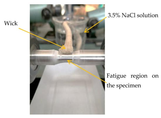
Figure 3.
The corrosion fatigue testing.
3. Results and Discussion
3.1. Microstructure of Experimental Alloys
Identification of intermetallic phases present in experimental AlSi7Mg0.6 alloys demonstrated the presence of the following phases (Figure 4): Mg2Si, Al15(FeMn)3Si2, and Al5FeSi. It is a common structure composition [,].
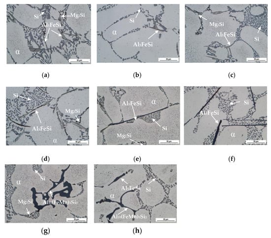
Figure 4.
Microstructure of experimental materials, etch 0.5 HF (a) AC; (b) AC + T6; (c) 2Fe; (d) 2Fe + T6; (e) 3Fe; (f) 3Fe + T6; (g) 3Fe + Mn; (h) 3Fe + Mn + T6.
The Mg2Si phase was observed in the metallographic section plane preferentially along the edges of the α-phase dendrites, near the eutectic Si and the needle phase Al5FeSi, in the form of dark black oval grains to small fine skeletal formations. The area fraction of the Mg2Si phases ranged from 0.2 to 0.5%, while no direct correlation was observed between the increased Fe content and heat treatment, and the amount and size of the Mg2Si phases.
When the Fe content increases, the amount of Al5FeSi phases in the microstructure increases too, which correlates with the works of [,,]. The change in morphology of the β-phase to the less harmful α-phase was not realized in the entire volume of the alloy, because the added amount of Mn did not correspond to the recommended one-half of the Fe content in the alloy, but was lower. As a result, in alloys 3Fe and 3Fe + T6, in addition to the α-Al15(FeMn)3Si2 phases in the form of skeletons, or in the form of Chinese script, the needle-shaped Al5FeSi phases (Figure 4g,h) were formed. To achieve a change in morphology of the β-phase in the larger part of the volume, it is necessary to add approximately 0.210 wt. % Mn to alloys with this higher Fe content (marked as 3Fe).
The calculation of Fecrit according to Equation (1) (Figure 5) shows that each experimental material has a content of Fe lower than the calculated value of Fecrit. The same results are observed according to the content of Si in Al-Si alloys [] calculation (Figure 5, Table 2).
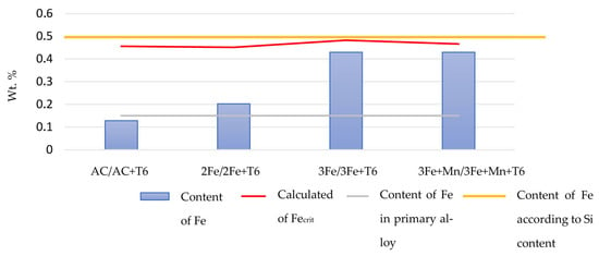
Figure 5.
The control of Fe content in experimental alloys.
A quantitative analysis was performed to evaluate the size (length and thickness) of the Fe-phase Al5FeSi and the area fraction of all Fe intermetallics (Table 3). The increase in the average length of Fe–needles is 91.7% in experimental alloy marked as 3Fe, with a content of 0.429% Fe, compared to experimental alloy marked as AC, with a content of 0.128% Fe (Table 3). The addition of manganese clearly had positive effect on the needle β-phase length. It was observed that the length of Al5FeSi needles (Table 3) was significantly reduced, although larger needles were also observed locally.

Table 3.
The quantitative analysis of Fe needle phases in experimental materials.
The effect of heat treatment on the length and thickness of needle β-phases is minimal based on the results of the average sizes of the Al5FeSi phase (up to melt 3Fe + T6) (Table 3), for example experimental alloys 3Fe + T6 have about 87.5% longer needles as experimental alloys AC + T6. The longest β-phases were observed in experimental alloys with the highest Fe content (3Fe = 0.429% Fe). These results correlate with the conclusion of Kuchariková et al. [], where higher Fe content (0.4% of Fe) leads to the formation of the longest Fe phases. In addition, it seems that combination of an insufficient amount of Mn and T6 caused an increase in the area fraction of Al5FeSi phases in experimental alloys 3Fe + Mn, which Belmares et al., Taylor, and Dinnis et al. [,,] also demonstrated in their work.
It is generally known that the presence of Fe-phases affects increased porosity formation, because large needles impede the flow of the melt, causing problems with its “run-in” and causing the presence of shrinkage pores (shrinkage). Porosity assessment is important because in aluminum alloys, the most common place for fatigue cracking to occur is considered to be pores or casting defects occurring on or near the surface of the sample. The larger the pore size and the shorter their distance from the sample surface, the lower the fatigue life of the alloys [,,]. Taylor [] also investigated the effect of Mn in an alloy with a higher Fe content on the porosity of castings and concluded that the presence of Mn does not guarantee an improvement in porosity. Mn seems to reduce a greater amount of porosity associated with increased Fe content only in alloys containing Cu, or at the correct Fe/Mn ratio [,,,]. The results (Table 4) confirm that an increase in porosity was noted in alloys with added Mn content. This increase may be directly related to the insufficient content of Mn added to correct the β-phase. The area fraction of pores was the largest in alloys in which Mn was intentionally added (Table 4). The largest average pore size was also recorded in these alloys. The smallest average pore size was recorded in alloys with the lowest Fe content and increased with increasing Fe content. The difference in the area fraction results between heat-treated and non-heat-treated samples was relatively small, ranging from 0.1 to 0.4%. These results also did not confirm the results of the work of Li et al., Yang et al. [,], in which the largest Fe-rich phases create the largest porosity (Table 3 and Table 4). The heat treatment also did not affect the pore size and content.

Table 4.
The quantitative analysis of porosity in experimental materials.
3.2. Mechanical Properties
The highest UTS and YS were observed in experimental alloys after heat treatment (Table 5). Results confirm that Mn leads to an increase in UTS and YS, as well as ductility. The increase was not significant; however, it is a normal measurement deviation. In general, heat treatment has a significant effect on increasing the mechanical properties of all experimental alloys. The more significant decrease in the agreed yield strength is probably related, in addition to the Fe phases, to the morphology and distribution of eutectic silicon, which, after heat treatment, has the shape of isolated particles, in contrast to the initial state, where it is observed as clumpy growing rods.

Table 5.
The results of the mechanical properties.
This result correlates with the conclusion of work by Li et al., Yang et al., and Kuchariková et al. [,,]. With increasing Fe content, the ductility decreased, with the alloy containing the highest Fe content exhibiting the lowest ductility—approximately two times lower than that of the AC alloy. After the addition of Mn, a subsequent increase was observed. A significant decrease in ductility was also observed in samples after heat treatment. The results of research work [,,,,] decelerated that the Al5FeSi phase decreased in ductility. The decrease in the experimental alloys after heat treatment maybe correlated with the twofold higher area fraction of Fe-rich needle phases (Table 3), but it is also connected to precipitation hardening and changes in the morphology and distribution of eutectic silicon (Figure 6).
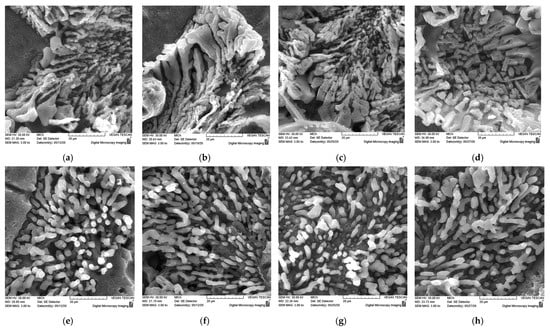
Figure 6.
Three-Dimensional morphology of eutectic Si particles, HCl, SEM. (a) AC; (b) AC + T6; (c) 2Fe; (d) 2Fe + T6; (e) 3Fe; (f) 3Fe + T6; (g) 3Fe + Mn; (h) 3Fe + Mn + T6.
The hardness results show a significant effect of heat treatment in increasing the hardness of the experimental alloys (Table 5). Results also show that an increasing amount of Fe-rich needle phases does not lead to a decrease in hardness. Heat-treated alloys, regardless of iron content, had almost twice the hardness compared to their initial state. With increasing Fe content, a slight increase in hardness was expected, since the Fe phases were hard; however, this was not confirmed. This is probably due to the fact that the Brinell hardness measurement captured a relatively large area of the test specimen during the measurement, and therefore it is highly likely that the decrease in hardness was directly related to the increasing porosity of the castings.
3.3. Fatigue Properties
The fatigue life evaluation of experimental alloys with increasing Fe contents in two different states (without and after heat treatment T6) was carried out in the high-cycle fatigue region. The test bars were loaded at three different loads (88 MPa, 78 MPa, and 68 MPa). The influence of the increasing Fe content on the fatigue curves of experimental alloys without T6 was manifested by a shift in the fatigue curves to the left (Figure 7a), i.e., alloys with higher iron content withstood a lower number of cycles at the same loading amplitude. The fatigue life results also correlate with the quantitative analysis of Fe needles phases (Table 3). These results are connected with findings of researcher works of [,,,,,], in which it was decelerated that alloys with a higher Fe content are more prone to cracking. Fe-rich β-phases form sites of higher stress concentrations, which can lead to the formation of microcracks and subsequent macrocracks. The presence of intermetallic iron phases reduces the fatigue life by at least 20%. Moreover, if a higher Fe content is present in the Al alloy, long β-phases occurring near the sample surface are also considered to be the main initiation sites. Regarding the influence of Fe-phases on the fatigue life of Al-alloys, it has been proven [,,,] that the most harmful for the alloy are the needle-like Al5FeSi phases.
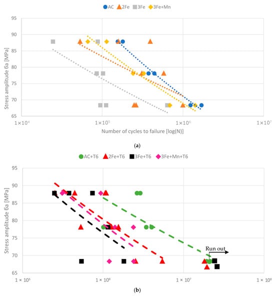
Figure 7.
The Wöhler curves of the fatigue life of experimental alloys (a) without T6, and (b) with T6 condition.
The addition of manganese has the opposite effect; the experimental alloys 3Fe + Mn will withstand a significantly greater number of cycles to failure than alloy 3Fe with the same iron content but without the addition of manganese (Figure 7a). The obtained results are not in agreement with other works [,,,] that dealt with the influence of surface and subsurface pores on decreasing fatigue life, as these pores act as initiation sites for fatigue cracking during cyclic loading, where large internal stresses arise. The results in Table 4 declared that alloys 3Fe + Mn (also 3Fe + Mn + T6) have the highest size and area fraction of porosity; nevertheless, these alloys have a better fatigue life than alloys without the addition of Mn (Figure 7).
The results of the fatigue test of alloy after heat treatment are documented in Figure 7b. The overall character of the fatigue curves after heat treatment copies the character of the curves material without T6 (Figure 7a), i.e., with increasing iron content, the fatigue life decreases, and the individual curves of alloys with increasing Fe content shift to the left. The application of heat treatment increased the fatigue life of the experimental alloys (Figure 7b). After heat treatment, the fatigue curves of alloys with the same iron content state shift to the right compared to the as-cast state (Figure 7), indicating that they can withstand a higher number of cycles. The results show that experimental material 3Fe + T6 has a higher fatigue life compared to experimental material with a chemical composition of primary AlSI7Mg0.6 alloy (AC).
In heat-treated alloys, the measured fatigue life was almost 10 times higher than in alloys without heat treatment. The increased fatigue life is related to the heat treatment, which increases hardness (thanks to the presence of Mg2Si phases in experimental alloys) and also affects the morphology of eutectic Si particles, which are spheroidised. Additionally, the size of porosity is lower in these alloys in comparison with the alloys without T6. Thus, the alloy becomes more resistant to stress. These results correlate with the work of Kuchariková et al. and Chen et al. [,], who observed the influence of the shape of eutectic Si on the fatigue life of castings. Alloys containing smaller round Si had a longer fatigue life than those where the eutectic Si was not thermally affected or modified.
The addition of Mn (experimental alloys 3Fe + Mn + T6) results in an improvement in the fatigue properties of the alloy, approximately to the level of melts with an Fe content of 0.202 wt. % (2Fe). During the fatigue test, in four cases at the lowest load of 68 MPa, there was no failure of the alloy by fatigue fracture, namely in two cases in alloy AC + T6, in one case in alloy 2Fe + T6, and in one case in alloy 3Fe + T6. These alloys were marked as run out (Figure 7b).
3.4. Corrosion Fatigue
The results of the fatigue test of experimental alloy with different iron contents, without and after heat treatment, which were simultaneously subjected to the action of a corrosive environment, are documented in Figure 8. The graph (Figure 8) contains the results of the fatigue test for samples not exposed to a corrosive environment and for those exposed to a corrosive environment (marked as AC + K, 2Fe + K, and so on) to clearly compare the effects of the corrosion. In terms of the nature of the curves of individual alloys, the results of corrosion fatigue tests correlate with those of the fatigue tests performed on experimental alloys without the influence of a corrosive environment. The highest corrosion fatigue life is in alloys with the lowest Fe content, while the lowest fatigue life occurs in alloys with the highest Fe content. The addition of manganese improves the fatigue life of alloys, but the effect was not so significant. These results confirm the knowledge of other researchers [,,,,], that the combination of cyclic mechanical loading and corrosive environmental conditions during service can significantly accelerate the initiation of fatigue cracks, ultimately leading to premature structural failure. As a result, corrosion fatigue is a critical factor limiting the application of aluminum alloys in transportation systems, especially in coastal regions or areas where de-icing salts are regularly used during winter months. In such environments, environmentally assisted cracking in aluminum alloys is typically initiated by the breakdown of the protective passive oxide film, which promotes localized pitting or intergranular corrosion and facilitates crack initiation. Under sufficiently aggressive environmental conditions, pit propagation proceeds until a transition to crack growth occurs, governed by anodic dissolution and hydrogen embrittlement mechanisms. In addition to surface defects, intermetallic phases serve as preferential sites for localized corrosion initiation in aluminum alloys [].
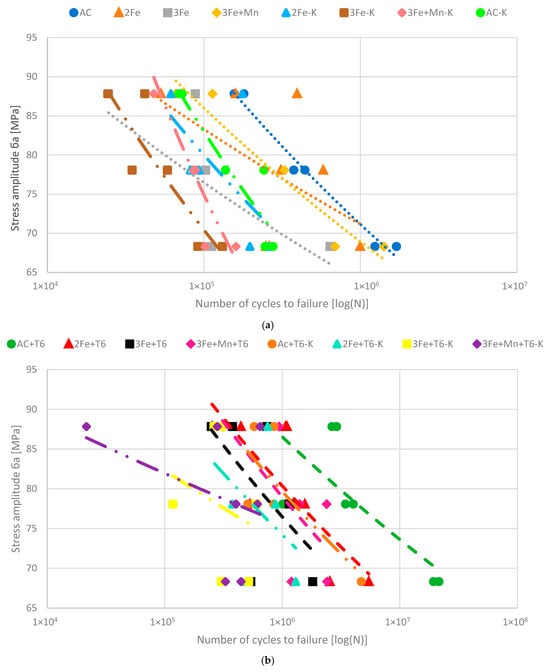
Figure 8.
The comparison of Wöhler curves for all experimental alloys after fatigue corrosion (a) without T6, and (b) with T6 condition.
From the mutual comparison of the results of the samples, in the as-cast state and after heat treatment, in a corrosive environment (Figure 8), it is clear that the application of heat treatment increased the fatigue life of the samples on individual levels (approximately by 1 order of magnitude). The curves of alloys with the same iron content after heat treatment, compared to the as-cast state, shift to the right—i.e., they withstand a higher number of cycles.
As a result of the corrosive environment during the fatigue test, i.e., by continuously applying a 3.5% NaCl solution to the stressed part of the test bar during the entire rotation period until fatigue fracture occurred, a decrease in fatigue life was recorded in all alloys. The decrease in fatigue life in the corrosive environment was probably due to the penetration of chloride ions into the casting defects located on the surface of the samples (Figure 9). The presence of chloride ions was detected by mapping EDX analysis, which provides information about the distribution of elements on the surface. Mapping EDX analysis demonstrated the presence of chloride ions in all investigated alloys. Chlorides in the casting defects (pores) act as an etchant and etch the matrix present mainly in the eutectic. This caused even small casting defects to enlarge, thereby becoming initiation sites for crack propagation. The negative effect of a higher content of Fe was also connected with the size of the eutectic Si. The Fe-rich phases act as nucleation sites for eutectic Si; therefore, as the amount of Fe-phases increases, the number of nucleation sites for Si particles also increases. Consequently, the structure of the matrix becomes softer, and corrosion propagates more easily through the matrix.
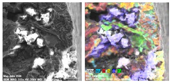
Figure 9.
Presence of chloride ions in the casting defects located on the surface of the 2Fe sample using mapping EDX analysis.
The comparison of fatigue properties was made through the timed fatigue limit for all experimental alloys (Table 6). The timed fatigue limit for the number of cycles of 105 was chosen as the comparison criterion for experimental alloys after corrosion attack. For heat-treated alloys, where the fatigue life was higher, the timed fatigue limit for the number of cycles of 106 was chosen as the comparison criterion.

Table 6.
The results of the timed fatigue limit.
The timed fatigue limit decreases in experimental alloys with increasing iron content. A more significant decrease is observed in the state without heat treatment (by 16.8%). In samples after heat treatment, it decreases by 12.1%. From the mutual comparison of the timed fatigue limit (Table 6) of samples without and after a corrosion exposure, it follows that the corrosive environment (3.5% NaCl) reduces the timed fatigue limit of alloys without T6 by an average of 7.5 MPa (15.6%) and of alloys after heat treatment by 6 MPa (5.8%). The addition of manganese has no significant effect on the timed fatigue limit. These results correlate with the conclusions of Kuchariková et al. and Elhasslouk et al. [,], who performed fatigue rate tests in a 3.5% NaCl solution and observed that a harsh environment significantly influenced the fatigue life of the aluminum alloys. In corrosion fatigue, the material is continuously exposed to a corrosive environment, ensuring the sustained presence of aggressive species at the fatigue crack tip. The resulting interaction between mechanical loading and electrochemical reactions accelerates crack growth, as localized corrosion at the crack tip induces material dissolution and embrittlement processes absent in purely mechanical fatigue [].
3.5. Fractography Analysis of Fatigue Fracture Surfaces
Macroscopic view of fracture surfaces of alloy samples with different iron content, at the same bending load, shows that with increasing Fe content in alloys, not only a decrease in fatigue life was observed, but also an increase in surface roughness. Several smaller fatigue areas were observed on experimental materials with a higher amount of Fe (0.429 wt. %) compared to the AC experimental alloy (Figure 10). This caused crack propagation in multiple directions.
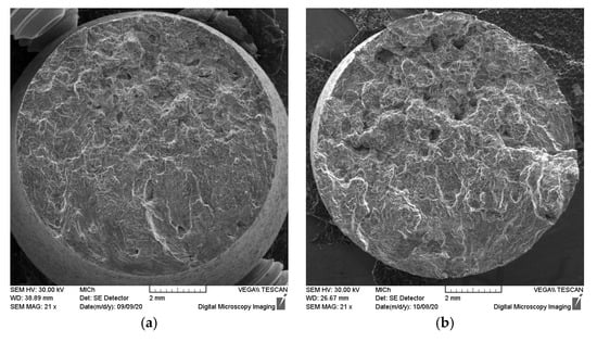
Figure 10.
Macroscopic view of fatigue fracture surfaces—Influence of Fe content. (a) AC alloy; (b) 3Fe alloy.
The initiation sites of fatigue cracks were identified near the edge of the samples and were identified as subsurface and surface casting defects (Figure 11). These results correlate with the findings of authors [,,], that the larger the pore size and the shorter their distance from the sample surface, the lower the fatigue life of the alloys. With increasing load and increasing Fe content in the alloy, the number of initiation sites increased. Measurement of the size of individual initiation sites showed (Figure 11) that with increasing load, even smaller casting defects became places of increasing stress, which led to the formation of multiple fatigue cracks.
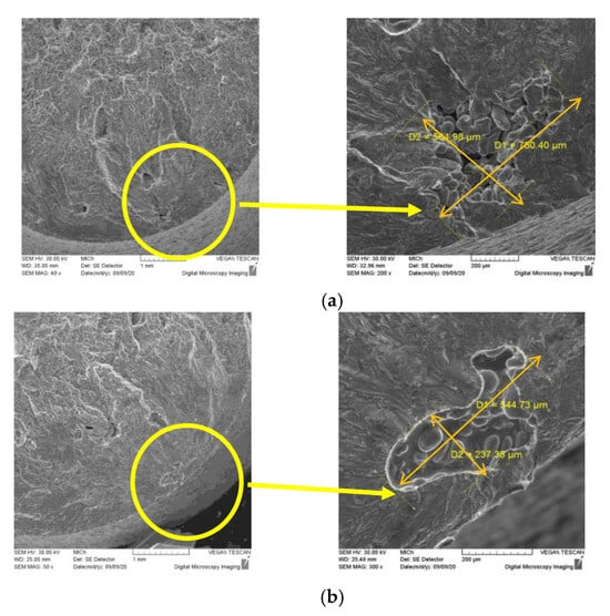
Figure 11.
Identification of the location and size of the initiation place in AC cast alloy. (a) at 68 MPa stress amplitude; (b) at 78 MPa stress amplitude.
Microfractographic evaluation of fracture surfaces of alloys with different iron contents did not show significant changes in the micromechanisms of failure depending on the magnitude of the stress amplitude. The fatigue fracture surface was characterized by transcrystalline fatigue failure of the α-phase (matrix) and interphase failure in places of occurrence of Fe-intermetallic phases (Figure 12). Typical fatigue signs—striations (Figure 12)—were identified on the fracture surface only rarely, occurring mainly in the area before the fracture; in other cases, a slight terraced propagation of the fracture occurred. The nature of the fracture in the final static rupture is related to the morphology and size of the eutectic silicon and intermetallic phases present in the structure. In all experimental alloys, in the final static rupture, trans-crystalline ductile fracture of the matrix with a pit morphology, and local occurrence of cleavage facets (Fe-phase fracture) was observed. The shape of the pits is related to the shape of the silicon particles.
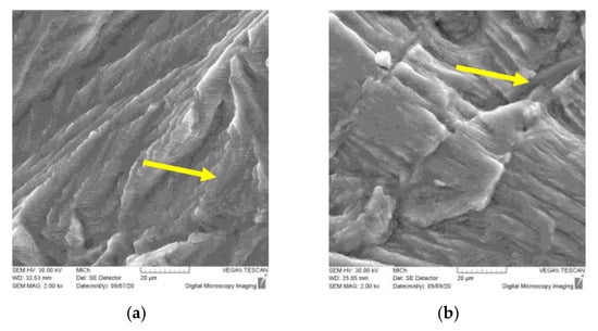
Figure 12.
The fatigue fracture of (a) α-phases—striations and (b) intermetallic phases.
The fractography analysis of alloy samples with different iron contents, which were exposed to a corrosive environment (3.5% NaCl) during fatigue testing (rotational bending), was quite complicated. The fatigue fracture surfaces of the corrosive samples remained largely degraded by the acting salt and other corrosion products. Therefore, only samples of 3Fe composition were evaluated, because the fatigue life of these samples is the lowest and the corrosion degradation of the fatigue region was not so significant. After the fracture, the samples were rinsed with distilled water and ethanol and dried with hot air. The nature of the fatigue failure and the initiation sites were identical to those of the samples without the corrosive environment (Figure 13).
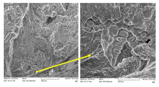
Figure 13.
The initiation sites of experimental samples 3Fe after corrosion environment.
On the fatigue fracture surfaces of the samples after the corrosion-fatigue test, several initiation sites were observed at different levels, which creates the so-called jump-like failure of the samples and a significant fragmentation at each selected load. Wang [] in his work investigated two types of initiation sites, namely the casting defect and the oxidation film. He concluded that the casting defects have a more harmful effect on the fatigue life of the alloy than the oxidation film. Surface casting defects were identified as the initiation sites of microcracks, also in this research. The inside of the casting defects, unlike the above-evaluated samples after the fatigue test, did not have a typical smooth surface, but the presence of corrosion products and local and partial corrosion failure of the α-phase matrix was observed. The character of the fatigue areas and the fracture area remain the same.
4. Conclusions
The most important findings of this research are:
The AlSi7Mg0.6 cast alloy with an iron (Fe) content identical to the standard for primary alloys (designated as AC) exhibits the highest mechanical properties in both conditions (without and with heat treatment). It is important to note that the mechanical properties of alloys with higher Fe content were not significantly reduced compared to the AC alloy. In other words, the addition of Fe did not degrade the mechanical performance beyond the typical measurement variability. Alloys with the highest Fe content demonstrated the lowest fatigue resistance. The experimental alloy 2Fe + T6 (0.202 wt. % of Fe) reached about 73% of the fatigue life value of the AC + T6 experimental material in both states (without and after corrosion damage). Exposure to a corrosive environment during fatigue testing led to a reduction in fatigue life across all experimental alloys.
Results from the experimental melts without heat treatment revealed that the 3Fe alloy (containing 0.429 wt. % Fe) exhibited the highest area fraction, length, and thickness of Fe-rich needle-like intermetallic phases. The maximum length of the β-phase in the 3Fe alloy was more than four times greater than that observed in the AC alloy. This alloy also exhibited the highest area fraction of porosity. Despite these microstructural characteristics, the 3Fe alloy demonstrated comparable ultimate tensile strength (UTS) and yield strength (YS) in the AC alloy. Of course, the ductility was the lowest, and the shortest fatigue life was observed, both in air and under corrosive conditions.
Conversely, the 2Fe alloy (0.202 wt. % Fe) exhibited the lowest area fraction, length, and width of Fe-rich needle phases. This reduction in Fe-phase morphology correlated with the formation of fewer and smaller pores. The mechanical properties of the 2Fe alloy—including UTS, YS, and ductility—were comparable to those of the AC alloy. In terms of fatigue life, both in air and corrosive environments, the 2Fe alloy performed similarly to the AC alloy and significantly outperformed the 3Fe alloy.
The results of the experimental melts subjected to heat treatment (T6) indicate that the alloy 3Fe + Mn + T6 (containing 0.429 wt. % Fe) exhibited the largest surface area fraction of Fe-rich needle-like phases. These phases were also the thinnest, contributing to the highest surface area fraction of pores. The maximum length of the β-phase in this alloy exceeded that of the β-phase of the AC + T6 alloy by more than a factor of six. Correspondingly, the largest average pore size was also recorded in this alloy. Despite these microstructural characteristics, the 3Fe + Mn + T6 alloy achieved comparable ultimate tensile strength (UTS) and yield strength (YS) with the AC alloy but exhibited the lowest ductility. Its fatigue life in non-corrosive conditions ranked among the lowest, and under simultaneous exposure to a corrosive environment, it demonstrated the poorest fatigue resistance of all tested alloys.
In contrast, the 2Fe + Mn + T6 alloy (0.202 wt. % Fe) displayed the smallest area fraction and length of Fe-rich needle-like phases, which resulted in a lower number of pores and smaller pore sizes. The mechanical properties of the 2Fe + Mn + T6 alloy—including UTS, YS, and ductility—were comparable to those of the AC + T6 alloy. Furthermore, its fatigue life, both in air and under corrosive conditions, was similar to that of the AC + T6 alloy and significantly superior to that of the 3Fe + Mn + T6 alloy.
The results of fatigue tests show that, regardless of the state of the samples (as-cast or after heat treatment), the corrosive environment (without or in 3.5% NaCl), in all cases, the fatigue life, together with the timed fatigue limit, decreased with increasing Fe content. This was caused not only by the increased porosity of the castings but also by the presence of large needle-like Al5FeSi phases, which were located near the surface of the samples. It was confirmed that the addition of Mn to an alloy with an Fe content (0.429 wt. % of Fe) will improve the fatigue life of the alloys in all states and environments. Fractographic analysis of fracture surfaces showed that the main site of fatigue crack initiation was mainly surface casting defects. How long the experimental alloy was able to withstand also depended on the size and location of the pores in the alloy. The larger their size and the shorter the distance from the sample surface, the lower their fatigue life.
Based on the experimental results obtained to date, it can be concluded that the alloy containing 0.202 wt. % Fe exhibits mechanical and fatigue properties comparable to those of primary alloys. Therefore, it can be inferred that secondary alloys with this iron content are suitable for the production of automotive cast components.
Author Contributions
Conceptualization, L.K. and E.T.; methodology, L.K. and E.T.; validation, L.K., I.Š. Z.Š. and E.I.; formal analysis, L.K., Z.Š., M.C., V.Z. and I.Š.; investigation, L.K., Z.Š., V.Z., E.I. and I.Š.; resources, L.K. and E.T.; data curation, L.K., M.C., V.Z. and E.T.; writing—original draft preparation, L.K.; writing—review and editing, L.K. and V.Z.; visualization, L.K. and E.I.; supervision, E.T.; project administration, E.T.; funding acquisition, E.T. All authors have read and agreed to the published version of the manuscript.
Funding
This research was funded by grant VEGA grant number [1/0461/24], grant KEGA grant number [004ŽU-4/2023], and grant KEGA grant number [009ŽU-4/2023].
Data Availability Statement
The datasets presented in this article are not readily available because the data are part of an ongoing study. The data presented in this study are available on request from the corresponding author.
Conflicts of Interest
The authors declare no conflicts of interest.
References
- Singh, R. Lightweight metals and alloys in electric vehicle manufacturing: Enhancing performance and efficiency. Int. J. Sci. Res. Arch. 2024, 13, 1735–1742. [Google Scholar] [CrossRef]
- Zhang, W.; Xu, J. Advanced lightweight materials for Automobiles: A review. Mater. Des. 2022, 221, 110994. [Google Scholar] [CrossRef]
- Yadav, V.K.; Gaur, V.; Singh, I.V. Corrosion-fatigue behavior of welded aluminum alloy 2024-T3. Int. J. Fatigue 2023, 173, 107675. [Google Scholar] [CrossRef]
- Li, S.S.; Yue, X.; Li, Q.; Peng, H.; Dong, B.; Liu, T.; Yang, H.; Fan, J.; Shu, S.; Qiu, F. Development and applications of aluminum alloys for the aerospace industry. J. Mater. Res. Technol. 2023, 27, 944–983. [Google Scholar] [CrossRef]
- Avramenko, T.; Michel, S.; Stutz, A.; Kollender, J.; Burda, I.; Hans, U.; Affolter, C.; Terrasi, G.P. Comparative Study on Corrosion Fatigue Susceptibility and Microstructural Effects in 6061-T6 and 6082-T6 Aluminum Alloys. Metals 2025, 15, 653. [Google Scholar] [CrossRef]
- Mahmood, A.A.; Kader, A.M.; Islam, M.B.; Hossain, R. Sustainable transformation of waste Aluminium into high-performance composites: A review. Int. J. Lightweight Mater. Manuf. 2025, 8, 194–204. [Google Scholar] [CrossRef]
- Bulei, C.; Kiss, I.; Alexa, V. Development of metal matrix composites using recycled secondary raw materials from aluminium wastes. Mater. Today Proc. 2021, 45, 4143–4149. [Google Scholar] [CrossRef]
- Gomes, L.F.; Kugelmeier, C.L.; Garcia, A.; Dela Rovere, C.A.; Spinelli, J.E. Influences of alloying elements and dendritic spacing on the corrosion behaviour of Al-Si-Ag alloys. J. Mater. Res. Technol. 2021, 15, 5880–5893. [Google Scholar] [CrossRef]
- Berlanga-Labari, C.; Biezma-Moraleda, M.V.; Rivero, P.J. Corrosion of cast aluminum alloys: A Review. Metals 2020, 10, 1384. [Google Scholar] [CrossRef]
- Qin, L.; Du, W.; Cipiccia, S.; Bodey, A.J.; Rau, C.; Mi, J. Synchrotron X-ray operando study and multiphysics modelling of the solidification dynamics of intermetallic phases under electromagnetic pulses. Acta Mater. 2024, 265, 119593. [Google Scholar] [CrossRef]
- Závodská, D.; Tillová, E.; Guagliano, M.; Kuchariková, L.; Chalupová, M. Fatigue resistance of self-hardening aluminium cast alloy. Mater. Today Proc. 2017, 4 Pt 1, 6001–6006. [Google Scholar] [CrossRef]
- Pastierovičová, L.; Kuchariková, L.; Tillová, T.; Zatkalíková, V.; Uhríčik, M.; Liptáková, T.; Chalupová, M. Effect of Mn addition on the corrosion and fatigue properties of a progressive secondary A357 alloy. Arch. Metall. Mater. 2024, 69, 1123–1130. [Google Scholar] [CrossRef]
- Bacaicoa, I.; Luetje, M.; Wicke, M.; Geisert, A.; Zeismann, F.; Fehlbier, M.; Bruckner-Foit, A. 3D morphology of Al5FeSi inclusions in high Fe-content Al-Si-Cu alloys. Procedia Struct. Integr. 2016, 2, 2269–2276. [Google Scholar] [CrossRef]
- Bjurenstedt, A. On the Influence of Imperfections on Microstructure and Properties of Recycled Al-Si Casting Alloy. Ph.D. Thesis, Jönköping University, Jönköping, Sweden, 2017. [Google Scholar]
- Kuchariková, L.; Medvecká, D.; Tillová, E.; Belan, J.; Kritikos, M.; Chalupová, M.; Uhríčik, M. The effect of the β-Al5FeSi phases on microstructure, mechanical, and fatigue properties in A356.0 cast alloys with higher Fe content without additional alloying of Mn. Materials 2021, 14, 1943. [Google Scholar] [CrossRef] [PubMed]
- Sankaran, K.K.; Perez, R.; Jata, K.V. Effects of pitting corrosion on the fatigue behavior of aluminum alloy 7075-T6: Modeling and experimental studies. Mater. Sci. Eng. A 2001, 297, 223–229. [Google Scholar] [CrossRef]
- Vu, N.N. Corrosion Fatigue Behaviors of Aluminum Alloys for Offshore Applications. Ph.D. Thesis, Interdisciplinary Graduate School Energy Research Institute, Nanyang Technological University, Singapore, 2016. [Google Scholar]
- Weber, M.; Eason, P.D.; Özdeş, H.; Tiryakioğlu, M. The effect of surface corrosion damage on the fatigue life of 6061-T6 aluminum alloy extrusions. Mater. Sci. Eng. A 2017, 690, 427–432. [Google Scholar] [CrossRef]
- Gruber, R.; Singewald, T.D.; Bruckner, T.M.; Hader-Kregl, L.; Hafner, M.; Groiss, H.; Duchoslav, J.; Stifter, D. Investigation of oxide thickness on technical aluminum alloys—A comparison of characterization methods. Metals 2023, 13, 1322. [Google Scholar] [CrossRef]
- Henderson, B.S.; Cudworth, K.F.; Wale, M.E.; Siegel, D.N.; Lujan, T.J. The tensile fatigue strength and endurance limit of human meniscus. J. Mech. Behav. Biomed. Mater. 2022, 127, 105057. [Google Scholar] [CrossRef]
- Chandran, K.S.R. The finding of the reciprocal relationship between fatigue (S-N) behavior and fatigue crack growth behavior, enabling interconversion of data in structural materials. Materialia 2022, 25, 101541. [Google Scholar] [CrossRef]
- Kachkouch, F.Z.; Noberto, C.C.; Babadopulos, L.F.A.L.; Melo, A.R.S.; Machado, A.M.L.; Sebaibi, N.; Boukhelf, F.; Mendili, Y.E. Fatigue behavior of concrete: A literature review on the main relevant parameters. Constr. Build. Mater. 2022, 338, 127510. [Google Scholar] [CrossRef]
- D7791-22; Test Method for Uniaxial Fatigue Properties of Plastics. ASTM International: West Conshohocken, PA, USA, 2022. [CrossRef]
- Behvar, A.; Haghshenas, M. A critical review on very high cycle corrosion fatigue: Mechanisms, methods, materials, and models. J. Space Saf. Eng. 2023, 10, 284–323. [Google Scholar] [CrossRef]
- Kuchariková, L.; Pastierovičová, L.; Tillová, E.; Uhríčik, M.; Zatkalíková, V.; Šajgalík, M. The influence of a corrosive environment on fatigue and mechanical properties of an Al-cast alloy with higher Fe content. Metals 2023, 13, 1019. [Google Scholar] [CrossRef]
- Jastrzębska, I.; Piwowarczyk, A. Traditional vs. automated computer image analysis comparative assessment of use for analysis of digital SEM images of high-temperature ceramic material. Materials 2023, 16, 812. [Google Scholar] [CrossRef] [PubMed] [PubMed Central]
- Belmares-Perales, S.; Castro-Román, M.; Herrera-Trejo, M.; Ramírez-Vidaurri, L.E. Effect of cooling rate and Fe/Mn weight ratio on volume fractions of α-AlFeSi and β-AlFeSi phases in Al7.3Si3.5Cu alloy. Met. Mater. Int. 2008, 14, 307–314. [Google Scholar] [CrossRef]
- Bösch, D.; Pogatscher, S.; Hummel, M.; Fragner, W.; Uggowitzer, P.J.; Göken, M.; Höppel, H.W. Secondary Al-Si-Mg high-pressure die casting alloys with enhanced ductility. Metall. Mater. Trans. A 2015, 46a, 1035. [Google Scholar] [CrossRef]
- Taylor, J.A. Iron-containing intermetallic phases in Al-Si based casting alloys. Procedia Mater. Sci. 2012, 1, 19–33. [Google Scholar] [CrossRef]
- Sigworth, G.K. Fundamentals of solidification in aluminum castings. Int. J. Met. 2013, 8, 7–20. [Google Scholar] [CrossRef]
- ISO 6892-1:2019; Metallic Materials—Tensile Testing—Part 1: Method of Test at Room Temperature. Available online: https://www.iso.org/standard/78322.html (accessed on 2 May 2021).
- Dybowski, B.; Adamczyk-Cieślak, B.; Rodak, K.; Bednarczyk, I.; Kiełbus, A.; Mizera, J. The microstructure of AlSi7Mg alloy in as cast condition. Solid State Phenom. 2014, 229, 3–10. [Google Scholar] [CrossRef]
- Pereira, J.C.; Gil, E.; Solaberrieta, L.; Sebastián, M.S.; Bilbao, Y.; Rodríguez, P.P. Comparison of AlSi7Mg0.6 alloy obtained by selective laser melting and investment casting processes: Microstructure and mechanical properties in as-built/as-cast and heat-treated condition. Mater. Sci. Eng. A 2020, 778, 139124. [Google Scholar] [CrossRef]
- Dinnis, C.M.; Taylor, J.A.; Dahle, A.K. Porosity formation and eutectic growth in Al-Si-Cu-Mg alloys containing iron and manganese. In Proceedings of the 9th International Conference on Aluminium Alloys (ICAA9), Brisbane, Australia, 2–5 August 2004; pp. 1016–1021. [Google Scholar]
- Ammar, H.R.; Samuel, A.M.; Samuel, F.H. Porosity and the fatigue behavior of hypoeutectic and hypereutectic aluminum–silicon casting alloy. Int. J. Fatigue 2008, 30, 1024–1035. [Google Scholar] [CrossRef]
- ANicoletto, G.; Konečná, R.; Fintová, S. Characterization of microshrinkage casting defects of Al-Si alloys by X-ray computed tomography and metallography. Int. J. Fatigue 2012, 41, 39–46. [Google Scholar] [CrossRef]
- Tebaldini, M.; Petrogalli, C.; Donzella, G.; La Vecchia, G.M. Estimation of fatigue limit of A356-T6 automotive whell in presence of defects. Procedia Struct. Integr. 2017, 7, 521–529. [Google Scholar] [CrossRef]
- Li, Q.; Wang, J.; Xue, C.; Miao, Y.; Hou, Q.; Yang, X.; Meng, Y.; Yang, Z.; Tian, G.; Su, H.; et al. Effects of Sr on Fe-rich intermetallics in recycled Al–Si–Cu alloys. J. Mater. Sci. 2024, 59, 11572–11595. [Google Scholar] [CrossRef]
- Yang, D.; Song, D.; Tang, C.; Zhao, Y.; Cai, Y.; Chen, J.; Zhang, Z.; Zhou, N.; Zhang, W. 3D morphological evolution of the Fe-rich phase and mechanical properties of the recyclable A356 alloy. Mater. Today Commun. 2024, 41, 110425. [Google Scholar] [CrossRef]
- Kuchariková, L.; Tillová, E.; Chalupová, M. The Si particles morphology in hypoeutectic Al-Si casts. Mater. Today Proc. 2016, 3, 1031–1036. [Google Scholar] [CrossRef]
- Wang, Q.G.; Apelian, D.; Lados, D.A. Fatigue behavior of A356-T6 aluminum cast alloys. part I. effect of casting defects. J. Light Met. 2001, 1, 73–84. [Google Scholar] [CrossRef]
- Huter, P.; Oberfrank, S.; Grun, F.; Stauder, B. Thermo-mechanical fatigue influence of copper and silicon on hypo-eutectic al–si–cu and al–si–mg cast alloys used in cylinder heads. Int. J. Fatigue 2016, 88, 142–155. [Google Scholar] [CrossRef]
- Chen, Z.W.; Ma, C.Y.; Chen, P. Eutectic modification of A356 alloy with Li addition through DSC and miedema model. Trans. Nonferrous Met. Soc. China 2012, 22, 42–46. [Google Scholar] [CrossRef]
- Bartawi, E.H.; Mishin, O.V.; Shaban, G.; Grumsen, F.; Nordlien, J.H.; Ambat, R. The Effect of trace level copper content on intergranular corrosion of extruded AA6082-T6 Alloys. Mater. Chem. Phys. 2023, 309, 128303. [Google Scholar] [CrossRef]
- Elhasslouk, M.M.M.; Esen, İ.; Ahlatcı, H.; Akın, B. Effect of a 3.5% NaCl−10% HCl Corrosive environment on the fatigue behavior of hot rolled aluminum 5083-H111. Materials 2023, 16, 4996. [Google Scholar] [CrossRef]
Disclaimer/Publisher’s Note: The statements, opinions and data contained in all publications are solely those of the individual author(s) and contributor(s) and not of MDPI and/or the editor(s). MDPI and/or the editor(s) disclaim responsibility for any injury to people or property resulting from any ideas, methods, instructions or products referred to in the content. |
© 2025 by the authors. Licensee MDPI, Basel, Switzerland. This article is an open access article distributed under the terms and conditions of the Creative Commons Attribution (CC BY) license (https://creativecommons.org/licenses/by/4.0/).