Abstract
Nickel superalloys occupy a reasonably broad niche in the industry. One of this group’s most common and well-known alloys is Inconel 718. Parts from Inconel 718 are used in aerospace, energy, automotive, and some other vital industries, which creates a demand for research and improvement of the machining conditions of this alloy. This article is devoted to the systematization and generalization of the accumulated experience of machining of Inconel 718 at turning operation. The research methodology is based on the Pareto distribution. In the study, more than 50 articles devoted to turning Inconel 718 were analyzed. The tool materials, methods, and types of coating used in turning Inconel 718 were analyzed. Finite element method modeling of processing processes has been considered. The trends in the selection of cutting parameters and the geometry of the cutting tool and finite element method modeling of processing processes have been considered. Lacunae for promising future research were formulated.
1. Introduction
Nickel-based alloys are widely used in modern engineering. One of the most advanced alloys of this group is Inconel 718. It is a high-quality heat-resistant alloy of nickel, chromium, and iron with the addition of niobium, molybdenum, aluminum, and titanium. The combination of high heat resistance (up to 650 °C) [1,2] and hardness determined its use in products in structural elements that work in difficult operating conditions, in particular, cladding of supersonic aircraft, gas turbines, elements and assemblies of rocket and aircraft engines [1], and elements of submarines [3]. In recent years, Inconel 718 has also been used in the automotive and oil industries.
The global market for commercial aircraft engines in 2021 was more than USD 80 billion. The main components of the aircraft engine are shown in Figure 1. Inconel 718 makes up more than 50% of the weight of aircraft engines. Inconel 718 accounts for over 54% of the nickel superalloy market, equivalent to over USD 4 billion in 2019, making it the most popular nickel superalloy used in the world [1].
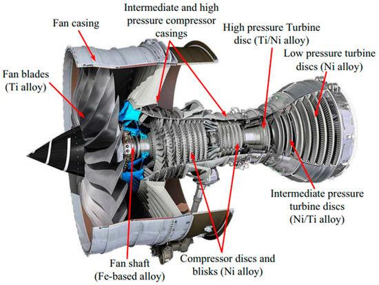
Figure 1.
Main components of an aircraft engine [4].
Historically, since its creation in the 1960s [2], Inconel 718 was considered a difficult-to-machine material, given the following characteristics: (a) high strength at elevated temperatures, (b) high hardness, (c) high material strength, (d) high degree of slander, (e) poor thermal conductivity, and (f) high tendency to build up edge (BUE) [4].
Considering the needs of the prospective market, researchers are actively investigating various factors affecting processing. The issue of cooling the cutting zone during processing is relevant when turning Inconel 718. It was found that tool wear at high-speed machining occurs because a large amount of heat transfers into the tool because of the low thermal conductivity of Inconel 718 [5]. A relatively common and effective cooling method is the minimum quantity lubrication (MQL) technology, which in some studies, was identified as more efficient than traditional lubrication [6]. The effectiveness of lubrication techniques can be increased using different combinations of lubricant emulsions and solid particles [7]. Currently, some researchers are focused on the development of applied applications for using cryogenic cooling [8], and the technique of high-pressure cooling (HPC) [9,10].
Considerable attention is paid to the study of cutting parameters’ influence on the machined surface’s quality and their further optimization to obtain a better result during machining [11]. The wear of the cutting inserts and the wear mechanism during the turning of Inconel 718 is also a relevant issue [12,13]. Several studies corresponding to the investigation of various cutting tool materials [14,15], coating type [16,17], and cutting tool geometry [18] as factors which affect the machining are investigated for productivity and efficiency of machining.
Although the number of Inconel 718 applications in the aviation industry expands, there are currently no relevant studies on the systematization and generalization of the accumulated experience in the field of machining of Inconel 718 parts, in particular, in turning, which determined the direction of the current research. Systematization and generalization of accumulated data were carried out based on the Pareto analysis. The current paper presents the statistical analysis of various technological factors considered in experimental studies and modelling based on processing 69 research papers published from 2004 to 2023. The statistical analysis aimed to evaluate which factors during machining Inconel 718 were more frequently studied and which were studied less. Special attention was paid to analyzing factors in the tool and coating materials categories, cutting parameters and technical environments, and tool geometry.
2. Materials and Methods
2.1. Material
Inconel 718 is a chromium–nickel super alloy. According to European standards, it has the designation NC19FeNb [3]. Despite its poor machinability, the alloy is relatively well processed by pressure and has good weldability. The primary analogues are (other brands) such as Alloy 718, Nicrofer 5219, Alvac 718, Haynes 718, and Altemp 718. Inconel 718 is available in bar, wire, sheet, plate, strip, etc. The chemical composition of Inconel 817 is listed in Table 1.

Table 1.
Chemical composition of Inconel 718 (%, wt) [19].
Since the composition of the alloy includes nickel, this increases its heat resistance during operation. Still, at the same time, it affects the cutting temperature, significantly reducing the temperature resistance of the cutting tool. Chromium increases hardness and strength, slightly reduces plasticity, and increases corrosion resistance. Niobium improves acid resistance and reduces corrosion in welded structures. Molybdenum increases elasticity, ultimate strength, anti-corrosion properties, and resistance to oxidation at high temperatures. Titanium increases the strength and density of steel, is a good deoxidizer, and improves machinability and corrosion resistance. The mechanical properties of the alloy are listed in Table 2.
Table 2.
Mechanical properties of the Inconel 718 alloy [3].
The classification of the main fields of application of the Inconel 718 alloy in products is given in Table 3.
Table 3.
Applications of the Inconel 718 alloy parts in industry [4].
2.2. Methods
The methodological basis of statistical analysis of experimental finding is Pareto distribution. The Pareto method is a rule of thumb that states that 80 percent of the effects are caused by 20 percent of the causes for many phenomena. This idea has found application in many industries. The Pareto distribution was introduced by Pareto (1987) to describe the distribution of wealth or income, and there are also some forms of this distribution [20]. Pareto distributions are the most popular models in economics, finance, and related fields [21]. The Pareto principle is essential for quality improvement because, based on it, by analyzing 20% of the factors, we can lead to a significant improvement. The probability density function (PDF) (Equation (1)) and the cumulative distribution function (CDF) (Equation (2)) of the Pareto distribution of the second kind are respectively given as [20]:
where λ and σ are shape and scale parameters, respectively. The average value of the Pareto distribution of the second kind is obtained (Equation (3)) [20]:
The scale parameter (Equation (4)) is expressed in terms of the average value as follows [20]:
The average target lifetime of the product when the process is in control is denoted by μ0 and the given experiment time t0 is written as a constant multiple of the average value of the process in management, for example t0 = aμ0. Then the probability of element failure (Equation (5)) before time t0 is denoted by p and given as [20]:
A process is considered in control if the process means the target point, i.e., μ = μ0 or λ = λ0 and σ = σ0. Thus, the probability of element failure when the process is under control is defined as (Equation (6)) [20]:
Feature analysis of research articles was caried out for following groups of factors: cutting tool material and coating type, cutting parameters, tool geometry, coolant, and lubrication environment for the purpose of identifying well- and poorly studied aspects of technological factors’ effects on machining quality and tool life when turning Inconel 718.
3. Machinability of the Inconel 718 Alloy
The main problem with using this alloy is its poor machinability. High strength and low thermal conductivity lead to rapid wear of the tool due to overheating of the cutting insert and high cutting forces. The properties responsible for the poor machinability of nickel-based superalloys, especially Inconel 718, are [22]:
- most of their strength is preserved during machining due to their high-temperature properties,
- they are susceptible to the rate of deformation and quickly harden, causing further wear of the tool,
- highly abrasive carbide particles contained in the microstructure cause abrasive wear,
- poor thermal conductivity leads to high cutting temperatures of up to 1200 °C on the rake face,
- nickel-based superalloys have a high chemical affinity with many tool materials, which leads to diffusion wear,
- welding and sticking of nickel alloys to the cutting tool often occurs during machining, causing severe cuts and changing the rake face of the tool due to subsequent pulling out of the tool materials,
- due to high strength, the cutting forces reach high values, excite the machine tool system, and can create vibrations that deteriorate the quality of the surface.
3.1. The Influence of the Cutting Tool Material on the Parameters of the Machining Process
The main requirements for any cutting tool material used for processing nickel-based alloys are [22]:
- good wear resistance,
- high hot hardness,
- high strength and durability,
- good thermal shock properties,
- adequate chemical stability at elevated temperature.
For turning Inconel 718, the following cutting insert materials are often used: PCBN (polycrystalline cubic boron nitride), mineral ceramics, and carbides [1,6].
The graph shows the use of one or another type of material for the cutting insert according to the frequency of cases (Figure 2):
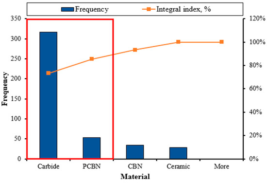
Figure 2.
Diagram of the distribution of the frequency of use of tool material.
Carbide is the most common material for machining the Inconel 718 alloy; its share in the number of cases is 75%. PCBN is in second place with a share of 12%. Let us consider each material and cases of its use in more detail.
3.1.1. Carbide
Carbide (WC-Co) is the industry’s most common cutting tool material. More than 65% of all produced carbide is used for machining metal [1]. The advantages of this type of cutting material are relatively low cost, high strength, and thermal conductivity. Due to their low thermochemical stability, they are quite suitable for machining Inconel 718 but are limited to a cutting range of 30 m/min to 70 m/min. On the other hand, (Cubic Boron Nitride) CBNs are used at higher cutting speeds of 200–350 m/min. However, they can be used at high feed rates due to their viscosity. Using carbides above the recommended feed rates and cutting speeds decreases tool life [23], making its use irrelevant for high-speed turning. Before the polycrystalline cubic boron nitride tool appeared, tungsten carbide was actively used for finishing the Inconel 718 alloy. However, even now, it occupies an extensive niche in turning since carbides have longer tool life than PCBN tools [14,23], while PCBN tools provide 4–6 times faster cutting speed.
At low cutting speeds of 15 m/min and 25 m/min, the primary type of tool wear was an adhesive fracture of the nose of the tool caused by the formation and shedding of growths. In contrast, at a 40 m/min speed, microcracks were detected on the rake face and a small amount of adhesive material of elements Ni and Fe. As the cutting speed increases, diffusion and oxidation between the tool and the workpiece weaken the carbide strength [24].
In a study on carbide tool wear, the following stages were identified: initial wear, normal wear, and sharp wear. At the initial stage of tool wear, bonds of elements Ni, Cr, and Fe, which are contained in Inconel 718, are formed on the surface of the cutting insert. Normal wear takes up most of the total wear and then turns into sharp wear. In the normal stage, the sticking process continues, leading to adhesion. At the stage of sharp wear, a growth is formed, which leads to further chipping of the material of the cutting plate. At the same time, increasing the cutting speed accelerates the onset of the stage of sharp wear, which negatively affects the tool life [25]. Various methods and types of coating are actively used to increase the productivity of carbides. In addition to coating, it can apply the pre-treatment method of carbide plates in a household microwave oven since they are microwave absorbers. Additional microwave treatment improves tool properties such as microhardness and wear resistance of the carbide tool [26].
For carbide inserts, preliminary preparation can be used by creating special microgrooves on the front surface of the carbide cutting insert. It was reported that microgroove-modified inserts have higher efficiency than non-modified ones. Cutting force and temperature were reduced for recommended cutting parameters (v = 35–80 m/min, f = 0.1 mm/rev, ap = 1.5 mm). The tool life of the micro-grooved cutting tool was 23.08% longer than that of a similar untreated tool. It also improves the process of chip destruction, which has a positive effect on the stability of the tool [27].
Carbide is a reasonably versatile solution for machining Inconel 718. It has good resistance and a low price. In general, Inconel 718 alloy is well suited for rough- and semi-finishing. However, its use for finishing is no longer relevant since, in this niche, it is inferior to polycrystalline boron nitride tools.
3.1.2. Cubic Boron Nitride
Cubic Boron Nitride (CBN) is one of the hardest materials. Its hardness is less than synthetic diamonds, but it has better temperature and chemical properties. Usually, this material is used for the rough machining of hardened alloys and cast iron. CBN can machine nickel-based superalloys with a hardness greater than 35 HRC at 200 to 350 m/min cutting speeds [23]. CBN has high thermal conductivity, hot hardness, and thermal stability. However, the performance of CBN tools still needs to be improved due to the extremely high manufacturing cost, which is about ten times the cost of the conventional carbide or ceramic tools [28]. This factor makes this type of tool unsuitable for industrial use which is confirmed by the results of the study of the Pareto diagram (Figure 2).
To increase the machining productivity, it is possible to apply microgrooves on the insert’s rake face. Since the most common type of wear for this type of material is adhesion [29,30], using microgrooves allows the adhesive layer formed during the machining to be stabilized. It prevents its further chipping by fixing the textured surface. Surface texturing on the flank face is a promising method for increasing the durability of the CBN tool during high-speed machining of hard-to-machine materials [29].
Another way to increase the economic feasibility of using this type of material is to apply coatings. The AlCrN-coated CBN tool can be used to machine Inconel 718 in the cutting speed range of 120 m/min, with lower feed rates and depths of cut. Using AlCrN coating increases the cost of the insert by only 2–3%, but reduces cutting force by 10–12%, flank wear by up to 15%, and improves surface roughness by up to 10% [17].
CBN cutting inserts are not the best choice for machining the Inconel 718 alloy. Despite its advantages, the too-high price of CBN cutting inserts limits their utilization in machining Inconel 718 applications. In these conditions the perspective alternative can be polycrystalline boron nitride.
3.1.3. Polycrystalline Cubic Boron Nitride
A new type of tool material was created based on CBN: PCBN. In a PCBN insert, the CBN grains are bonded by a ceramic such as TiN or TiCN, which acts as a binder for the CBN grains [31]. PCBN inserts are divided into two types: low content of cubic boron nitride CBN (40–70%) and high content of CBN (85–90%). Thanks to the low content of CBN, it was possible to create a new generation of tools that demonstrated increased hardness and viscosity [23]. PCBN inserts can withstand cutting temperatures above 1000 °C [14]. The cutting edge can be sharper due to the improved strength of PCBN tools, making them suitable for finishing operations at higher cutting speeds than carbide and ceramic tools. The finished surface machined with the PCBN tool achieves a more consistent quality and better surface roughness during machining [15,23]. A significant disadvantage of this type of tool is its high cost, but it is lower than that of a CBN tool [32].
Overall, PCBN tools are the appropriate choice when hard material (>50 HRC) is to be machined, offering high performance in terms of quality surface finishing. Due to their excellent properties, PCBN tools are increasingly used for the hard machining of various materials [23].
The main PCBN tool wear types are chipping, notch wear, flank wear, and built-up edge. PCBN tool life is very sensitive to the cutting speed [33]. Tool life decreased by 250% with increasing speed from 250 m/min to 350 m/min. In comparison, the effect of feed on tool life is not significant. Depth of cut also has a substantial impact on PCBN tool life [14]. Percentage CBN content from 45% to 60% and cutting speed from 250 m/min to 300 m/m ensure the best surface quality and tool life. The low CBN content in the tool has a positive effect on increasing the tool’s life. Throughout the machining process, the roughness of the machined surface is negligible, but towards the end of the tool life, the roughness increases due to the wear of the insert radius nose [23]. Tool life can be increased by applying coatings. For example, a TiN-coated PCBN tool resulted in ~20% higher tool life than equivalent uncoated PCBN inserts when machining Inconel 718 at 250 m/min. In addition, the machining efficiency is affected by the shape of the insert. For example, round inserts have significantly longer tool life than diamond/C-type tools at low cutting speeds (150 m/min). Still, no significant difference was observed at the higher parameters of 300 and 450 m/min [34].
It can be concluded that PCBN is a good choice for high-speed and finish machining of Inconel 718 alloy because it has high hardness and can withstand significant temperatures, which is essential when machining Inconel 718. Despite the relatively high price, this type of tool can be used for finishing critical parts, as it allows a good and constant quality of the treated surface to be obtained.
3.1.4. Ceramic
Ceramic cutting tools are mainly used for machining hard materials in the industry due to their unique mechanical properties. The high-temperature resistance of ceramic tools makes them suitable for high-speed machining of materials with abrasion and corrosion resistance, high hardness, and low chemical affinity. They have a longer life than carbide tools [22,35].
Ceramic tools based on aluminium oxide (aluminium oxide (Al2O3) and silicon nitride (Si3N4)) are suitable for machining nickel alloys. The fracture toughness of Al2O3 ceramics can be increased by adding ZrO2, and its thermal shock resistance by adding TiC and TiN. Alumina combined with TiC improves the thermal properties of the insert. Such a combination of tool material chemical composition results in five times higher cutting speeds than carbide tools (120–240 m/min). However, thermal and mechanical shock resistance is not significantly improved compared to tungsten carbides. Silicon carbide (SiC) fibers or fibers are added to increase the strength of Al2O3 ceramic tools and increase thermal conductivity because SiC has a very high tensile strength. Alumina ceramics (Al2O3 + SiCwhisker), reinforced with filaments, can achieve cutting speeds ranging from 200 to 750 m/min and feed rates from 0.18 to 0.375 mm/rev and have increased strength [23,32].
R. P. Zeilmann et al. [35] compared ceramic inserts with SiAlON and Al2O3 + SiCwhisker and investigated the cooling effect. A water-miscible vegetable oil emulsion, Vasco 1000, with a concentration of 10%, was used as a cutting fluid. The cutting parameters were the same throughout the experiment: cutting speed 250 m/min, feed = 0.2 mm/rev, and depth of cut = 1.5 mm. It was found that the best conditions for wet turning were achieved with the SiAlON insert. The tool life was 2.06 min. The wear was higher for the Al2O3 + SiCwhisker tool, and the tool life was about 1 min. The predominant wear types for ceramics (SiAlON) were notch wear and flank wear. These are the main causes of insert destruction, which limits the tool life. Oxidation and diffusion also occur due to high cutting temperatures. At the same time, for the Al2O3 + SiCwhisker tool, the main type of wear was more intensive notches. When turning without liquid, the result was the opposite; the stability time of the SiAlON insert was 0.75 min, while the tool life of the Al2O3 + SiCwhisker, insert was 1.25 min. It can be said that SiAlON is the more appropriate material for machining with the use of cutting fluid. This is due to its excellent strength, abrasion resistance, and good chemical stability.
A study by M. A. Shalaby et al. [32] compared different types of ceramic tools. At a cutting speed of 150 m/min, the Al2O3 pure ceramic tool had 1.13 times longer tool life than the Al2O3 + SiCwhisker tool. A similar result was obtained at a cutting speed of 250 m/min, at which the tool life of the Al2O3 tool was 1.26 times greater than that of the Al2O3 + SiCwhisker tool.
The ceramic tool has not been widely used in the machining of Inconel 718. Despite its properties, it is inferior in versatility to the carbide tool, and the niche of high-speed machining is more actively occupied by the polycrystalline cubic boron nitride tool. The characteristics of all analyzed materials can be seen in comparative Table 4.
Table 4.
Characteristics of tool materials when machining Inconel 718.
It can be concluded that, as of now, carbide is still the most common and universal solution for turning Inconel 718. In general, the niche of existing tool materials used for machining Inconel 718, their chemical and physical properties during machining, and the mechanism of wear are sufficiently researched.
3.2. Effect of Coating of Cutting Inserts on Cutting Parameters and Stability
Coatings on cutting tools are crucial because they directly affect the interaction between the cutting tool and the chip formation on machining operations. Various coatings are applied to cutting tools to increase wear resistance and prevent sticking at elevated cutting temperatures. Coatings also act as thermal barriers, which leads to a decrease in the amount of heat transferred in the cutting tool [36].
Coated tools have a complex material structure consisting of a base coated with a hard, anti-friction, chemically inert, and thermally insulating layer approximately one to several micrometres thick. Thus, coated tools offer better protection against mechanical and thermal stresses, reduce friction tool-chip interaction, and improve wear resistance over a wide range of cutting temperatures [37].
The most common coating methods for the cutting tool used to process the Inconel 718 alloy are the chemical vapor deposition (CVD) method and the physical vapor deposition (PVD) method. The moderate temperature method (MT-CVD) is also used.
According to the results, the share of the PVD method in the number of cases is 75%, the CVD method is 24%, while the MT-CVD method has only 1% (Figure 3).
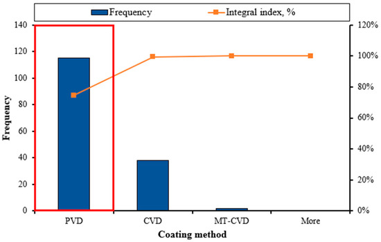
Figure 3.
The most common methods of coating the tool when machining the Inconel 718 alloy.
Vapor deposition is characterized by a process in which coating elements are evaporated into atoms, molecules, or ions in a vacuum and then condensed on the substrate surface to form the desired coating. According to the principle, vapor deposition methods can be classified into chemical vapor deposition (CVD) and physical vapor deposition (PVD) [38]. A comparison of PVD and CVD methods is shown in Table 5.
Table 5.
Comparison of PVD and CVD methods [38].
Let us consider the most common types of coverage in the analyzed studies (Figure 4).
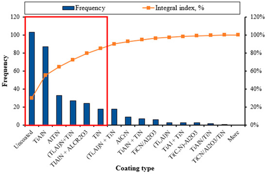
Figure 4.
The most common types of coating of cutting inserts when turning Inconel 718.
Based on the obtained data, we have the following distribution:
- 30% of the inserts had no coating.
- 25% of the inserts had a TiAlN coating.
- 10% had AlTiN coating.
- 8% had (Ti,Al)N + TiN coating.
- 7% had TIAlN + AlCr2O3 coating.
- 5% had TiN coating.
Gürgen et al. [36] compared a single-layer PVD TiAlN coating and a multilayer MT-CVD TiCN/Al2O3/TiN deposited on a carbide tool. Both coating methods have advantages such as reduced friction and cutting force comparing to uncoated inserts, but PVD coating provides a smoother surface for the Inconel 718 workpiece than MT-CVD coating. In addition, PVD TiAlN coating provides better wear resistance of cutting tools than the MT-CVD TiCN/Al2O3/TiN multilayer coating.
J. Zhao et al. [39] studied how the coating thickness of carbide inserts by the PVD method and TiAlN coating affects the dry turning of Inconel 718. It was established that an insert with a coating thickness of 1 μm (TiAlN-1) has a 15.23% higher microhardness. In addition, TiAlN-1 had a 4.17% better surface roughness. The measured yield forces of TiAlN-1 and TiAlN-2 decreased by approximately 27.46% and 23.51%, or 34.85% and 21.52%, compared to the uncoated tool at the cutting speed of 90 or 120 m/min in the initial stage tool wear. The cutting temperatures of TiAlN-1 and TiAlN-2 were reduced by approximately 9.57% and 5.80%, or 6.60% and 2.39%, compared to the uncoated tool at cutting speeds of 90 or 120 m/min. The cutting temperature of TiAlN-1 was reduced by approximately 19−30 °C compared to TiAlN-2 within the cutting speed range of 30−120 m/min.
AlCrN-coated CBN inserts exhibit excellent resistance to the heat generated in the tool-workpiece interface. The AlCrN coating is only 2–3% more expensive than a conventional uncoated CBN insert, but the coating reduces cutting forces by 10–12%, flank wear by 15%, and surface roughness by 10%. The AlCrN-coated CBN tool can process difficult-to-cut materials at a cutting speed of 120 m/min, with a lower feed rate and depth of cut [17].
The application of coatings is a very effective method of increasing the stability of any cutting tool used for machining Inconel 718 and increasing its productivity with a slight increase in the cost of the cutting insert. As can be seen from the study, when machining Inconel 718, single-layer coatings applied by the method of PVD are the most common due to their relatively low cost and the effectiveness of the resulting coatings.
3.3. Influence of Technological Environments on Cutting Conditions
High cutting temperatures during machining always lead to aggressive adhesive wear on the tool surface. Traditionally, cutting fluid is used to cool and lubricate the cutting process, thereby reducing tool wear and increasing tool life. The cost of cutting fluids is approximately 7–17% of the total cost of the machining process. In recent years, several technologies have been developed to control the temperature in the cutting zone to improve the overall efficiency of the process, such as cryogenic cooling, solid coolants/lubricants, flood cooling, and MQL. High-pressure coolant (HPC), is an internal tool that uses compressed air/gases [40]. Cooling significantly reduces the temperature in the cutting zone with a percentage share of 83.53% (the cutting speed takes second place with a contribution of 13.68%) [41].
When comparing dry, wet, and cryogenic turning, the highest tool life was obtained with cryogenic (nitrogen) turning, while the lowest tool life was obtained with dry turning. Tool life was almost 133% longer for wet and cryogenic turning than dry. Abrasion is the leading cause of high flank wear in dry turning. In the case of wet and cryogenic turning, chipping and adhesion were the leading causes of wear. Also, cryogenic turning consumes less energy than wet turning since the installation consumes less energy [8], and is safe for the environment [40]. In another study comparing LN2, LCO2 and traditional lubrication, traditional lubrication had the best results for carbide tool life, while LN2 shows lower tool life. LN2 and LCO2 showed higher cutting force when machining compared to traditional lubrication. This phenomenon can be explained be lower gas density in comparation to a liquid fluid lubrication. Regarding the roughness of the machined surface, traditional lubrication and LCO2 obtain a lower roughness to be obtained when turning with LN2. Of the listed methods (traditional, liquid nitrogen LN2, and carbon dioxide LCO2) LN2 was noted by researchers as the most acceptable [42]. The tool for cryogenic cooling is shown in Figure 5.
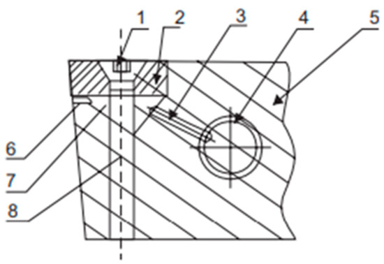
Figure 5.
Tool for cryogenic cooling [40], where, 1—screw head, 2—insert, 3—small hole passage, 4—liquid nitrogen entry point, 5— tool holder, 6—very small hole for gaseous nitrogen passage, 7—expanding chamber for liquid nitrogen, 8—threaded screw.
Another study examined the effects of LN2 on vibration, machined surface roughness, and ceramic insert wear. Compared to dry machining, the use of LN2 significantly reduces vibration acceleration, improves the quality of the machined surface, reduces the temperature on the tool-chip surface and friction between the tool-chip surface, reduces the shear strength of the workpiece material and, as a result, reduces tool wear [43].
Dry high-speed machining of Inconel 718 is not industrially rational, although it has certain advantages because the use of cutting coolants can cause specific problems related to environmental concerns, worker health, costs, and other important issues regarding its application. In addition, dry machining has such advantages as reduced skin and respiratory diseases and other health problems, and is safer for the environment due to the absence of coolant residues on machined components, which reduces or eliminates cleaning costs and reduced disposal costs and a result, the associated energy consumption [35].
HPC is a machining technology in which high-pressure fluid is fed to the tool and the workpiece. High pressure promotes better liquid penetration into the tool-workpiece and tool-chip interface zones (Figure 6) [40].
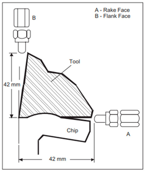
Figure 6.
Position of cutting fluid hoses [40].
It was found that increasing the contact area by 12% reduces flank wear by 45% for a carbide tool [44]. H. Khochtali et al. [10] compared the conventional cooling method and the HPC method for a coated carbide tool. It was established that using HPC allows for improved chip fragmentation, reduced cutting force, and doubled tool life. Compared to conventional lubrication, HPC lubrication increases tool life by 110% and 76%, respectively.
Another lubrication technique which was considered in the review was MQL. The oil mixes with the air, forming an aerosol, and is fed close to the cutting edge. In an MQL application, heat transfer occurs predominantly in the vapor mode, which is more efficient than the convection heat transfer common in conventional wet turning [40]. The progression of the average wear of the main side according to the used cooling medium is shown in Figure 7.
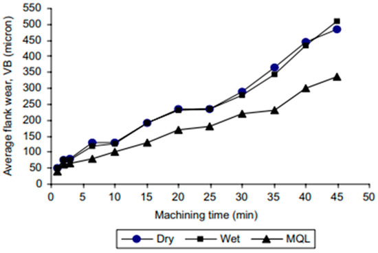
Figure 7.
Progression of average principal flank wear [40].
When machining using MQL for all tool types and cutting parameters, better results were shown than with other types of lubricants, which in turn indicates that a small amount of lubricant is sufficient when machining Inconel 718. The ceramic tool showed less tool wear at both cutting speeds with MQL and without lubrication, but with constant lubrication feed, notches formed. The carbide insert showed the greatest wear under non-cooling conditions. An insert made of cubic boron nitride at 150 m/min and in conditions without lubrication underwent adhesive wear [6]. For a carbide tool, the use of the MQL method is rational and allows obtaining a higher quality surface and tool life than in conditions with air cooling using a vortex tube and conditions without cooling [41].
A positive effect on the roughness of the treated surface can be achieved using a lubricant based on soybean oil by adding CuO particles during cooling by the MQL method. During the study, it was found that the percentage contribution of the flow rate to the surface roughness is 24.97%, the cutting speed is 21.83%, the feed is 0.78%, and the mass % of nanoparticles has the greatest influence and is 52.43% [45]. From this, it can be concluded that using lubricant with the addition of nanoparticles can improve the quality of the treated surface. But it is worth considering that the oil’s viscosity decreases as the temperature increases. As the cutting speed increases, the temperature increases, and therefore the viscosity decreases. This reduced viscosity cannot remove heat from the cutting zone at high cutting speed. Thus, at high cutting speed, the surface roughness begins to increase due to the reduced viscosity of the nanofluid. An increase in the concentration of nanoparticles in the base fluid causes an increase in the number of nanoparticles at the interface between the tool and the workpiece. This results in less contact between the workpiece and the tool, acting as a spacer between the tool and the workpiece, thus reducing the surface roughness [45].
Turning Inconel 718 alloy without cooling is inefficient due to inefficient cutting modes and low tool life. Cryogenic cooling methods have not yet proven their effectiveness and are difficult to implement from a technical point of view on existing serial equipment in production conditions. The conventional cooling method is effective but inferior to the MQL method in its efficiency. Minimum-quantity lubrication is a promising and effective cooling method when turning Inconel 718. This technique allows for good cooling, low energy consumption, and the use of coolant. It makes it possible to use various ecological types of coolant, which reduces the harmful impact on the environment and per worker and the cost of disposal or recycling.
3.4. Analysis of the Main Trends When Choosing Cutting Parameters
Cutting parameters have a significant impact on the machining of any material. During the study, attention was focused on such main factors as cutting speed, cutting depth, and feed speed.
Cutting speed affects machining productivity, tool life, machined surface roughness [3], vibration and cutting power [46]. In addition, the cutting speed affects chip formation. During machining, increasing the cutting speed, in turn, increases the friction coefficient at the chip-tool interface, which further increases the cutting temperature. A tightly twisted spiral chip is produced at the highest cutting speed, while a twisted chip is produced at the lower cutting speed. When machining Inconel 718, a toothed chip is mainly formed. An increase in the cutting speed leads to an increase in the degree of plastic deformation of the processed material due to intensive heat generation and rapid wear of the tool [47]. Also, the feed affects the roughness of the floor, power consumption, and vibration. Increasing the level of cutting speed generally caused an increase in roughness and vibration, while power consumption decreased with increasing cutting speed [46]. By systematizing the available data on the studied ranges of cutting parameters, distribution diagrams were obtained (Figure 8).
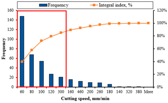
Figure 8.
Statistical distribution of cutting speed values when machining Inconel 718 alloy.
According to the study, the following values of cutting speeds are most often used for machining Inconel 718:
- 40% of cases—60 m/min;
- 17% of cases—80 m/min;
- 14% of cases—100 m/min;
- 7% of cases—120 m/min;
- 6% of cases—300 m/min.
This distribution (Figure 8) confirms that the cutting speed of 60–80 m/min is optimal for a carbide tool. At high cutting speeds with carbide inserts, very rapid tool wear occurs [8,35], because a large amount of heat is generated, and Inconel 718, due to its low thermal conductivity, transfers most of this heat to the tool, which is the main reason for rapid wear. The tool has no severe signs of damage at low speeds, and wear is uniform. The best roughness was obtained with a 190 m/min cutting speed. Tool wear at cutting speeds of 60 m/min and 90 m/min is uniform and shows no signs of severe damage. The tool is chipped in a heap with very fast wear at high speeds [39]. At the same time, at too low cutting speeds, 15 mm/min and 25 mm/min, adhesive wear of the tool is observed [10].
When the cutting speed changed from 50 m/min to 35 m/min, the tool life of the carbide tool increased by almost 200% [8]. Increasing of cutting speed results in increased wear. When comparing the cutting speeds 60/90/120 m/min, the highest wear of carbide tools was observed at 120 m/min, while for ceramic and CBN tools, wear decreased with increasing cutting speed (90–120 m/min) [12].
The depth of cut (ap)—is the amount of allowance removed in one pass. The depth of cut affects such factors as machining performance, cutting forces [3,14,48], power, and tool life. Increasing the cutting depth significantly reduces tool life [14]. The effect of depth of cut on surface roughness is insignificant [41].
The following depth-of-cut values are used for machining Inconel 718 (Figure 9):
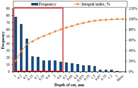
Figure 9.
Statistical distribution of values of depth of cut when machining Inconel 718 alloy.
- 21% of cases—1 mm;
- 18% of cases—0.2 mm;
- 13% of cases—0.5 mm;
- 6% of cases—0.15 mm and 0.1 mm;
- 5% of cases—0.25 mm, 0.4 mm, and 2 mm;
- 4% of cases—0.6 mm.
Cantero et al. [14] reported about the effect of depth of cut on the wear and tool life of PCBN tools. It was found that reduction of depth of cut did not affect the wear rate of PCBN cutting inserts. For the SiN insert, the minimum wear was measured at cutting parameters of 60 m/min, 0.1 mm/rev, and 0.5 mm, which correspond to other experimental results [18]. It was defined that feed rate significantly affects the chip formation, the quality of the machined surface, and the machining power. Increasing feed rate leads to increasing machining power because of increasing cut material thickness [46]. Based on the analysis of experimental data, a statistical distribution of feed values was determined in the range from 0.08 mm/rev to 0.4 mm/rev (Figure 10).
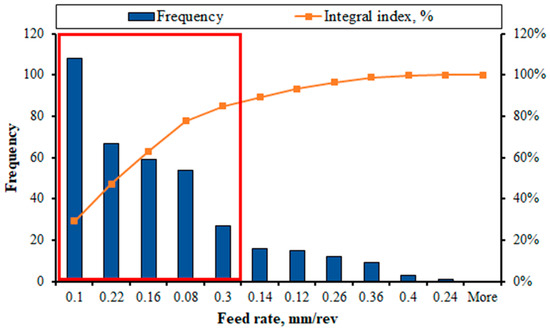
Figure 10.
Statistical distribution of feed values when machining Inconel 718 alloy.
We have the following distribution of feed values:
- 29% of cases—0.1 mm/rev;
- 18% of cases—0.22 mm/rev;
- 16% of cases—0.16 mm/rev;
- 15% of cases—0.08 mm/rev;
- 7% of cases—0.3 mm/rev.
In some studies, it was reported that feed rate significantly affects the cutting force when turning Inconel 718 compared with lubrication conditions and cutting speed. The influence of the feed rate on the forces is 93.75% for the main cutting force, 75.26% for the feed force, and 32.28% for the radial cutting force. In addition, the feed rate affects the roughness of the machined surface at 88.05%. However, the effect of feed rate on the cutting temperature was defined as minimal, only 0.37% [41]. Lower surface roughness is recorded at lower feed rates. Increasing feed rate results in raising adhesion and built-up formation, which is accompanied by increasing chatter vibrations [46].
3.5. Geometry of the Cutting Tool
The geometry of the cutting insert significantly affects chip formation, cutting force and surface roughness. In feature statistical study the distributions of tool cutting angle, clearance angle, rake angle, and corner radius were analyzed.
Tool cutting angle is the angle between the projection of the main cutting edge on the main plane and the feed direction. This angle affects the chip formation, shape, direction of its rise, and the thickness.
According to the analysis, the most common tool-cutting angles are 95° in 50% of cases, 45° in 32% of cases, and 91° in 11% of cases (Figure 11).
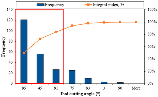
Figure 11.
The most common values of the tool cutting angle when machining Inconel 718.
The clearance angle is the angle between the cutting insert’s upper surface and the workpiece’s surface. This angle affects chip formation, temperature, and tool life. Depending on the type of material being processed, the clearance angle can be positive, neutral, or negative. The results of the analysis of the most common clearance angles when machining the Inconel 718 alloy are shown in (Figure 12).
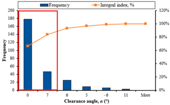
Figure 12.
The most common clearance angle values when machining Inconel 718.
The most common clearance angles of 0° in 66% of cases and a positive angle of 7° in 18% of cases.
Using a neutral clearance angle can reduce the cutting force. The positive clearance angle helps to reduce friction between the insert and the workpiece, which reduces the cutting temperature and increases tool life.
The rake angle significantly determines the cutting force by affecting the rake angles during the cutting process. Bigger rake angles tend to decrease cutting force when machining Inconel 718 [49]. The results of the analysis are shown in (Figure 13).
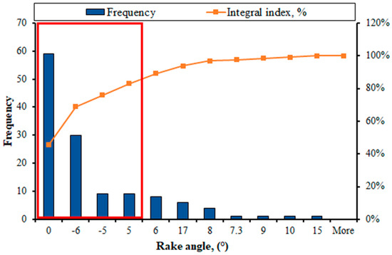
Figure 13.
The most common values of the rake angle when machining Inconel 718.
We have the following distribution of rake angles:
- 46% of cases—angle 0°;
- 23% of cases—angle −6°;
- 7% of cases—angles of −5° and 5°.
The corner radius of the insert is rounding the corner of the top of the cutting insert. The corner radius has a significant effect on the roughness of the machined surface [3,36], as well as on the stability of the cutting tool during machining. A larger radius is used for high feed rates and greater depths of cut because it has a stronger cutting edge. A smaller radius is used for shallower depths of cut and helps reduce vibration, but it has less cutting-edge strength. In the percentage contribution of the radius, feed rate, and coverage of the tool, the influence on the quality of the machined surface of the part is 77%, 19%, and 4%, respectively. Lower corner radius results in lower surface roughness [3,36]. This finding was verified in other research in which it was defined that 0.4 mm corner radius ensures lower cutting temperature when turning Inconel 718 with SiN and CBN tools [18].
It can be seen that the most common insert corner radius values are 0.8 mm in 54% of cases and 0.4 mm in 19% of cases. It can be summarized that the most common geometry when machining Inconel 718 is: tool cutting angle—95°, clearance angle—0°, rake angle—0°, corner radius 0.8 mm (Figure 14).
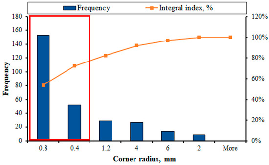
Figure 14.
The most common values of corner radius of the cutting insert when machining Inconel 718.
3.6. Cutting Edge Microgeometry
In this research of authors Arunachalam et al. [50] surface integrity of Inconel 718 machined by cemented carbide tools was investigated. From the results, a honed (rounded) cutting edge results in a better surface roughness parameter than a sharp or chamfered cutting edge. Higher surface roughness values for sharp cutting edges may be related to excessive chipping of sharp cutting edges during feed and cut. On the contrary, the slight rounding of the honed cutting edge prevents it from chipping excessively. A similar effect is achieved with chamfered cutting edges. However, higher cutting forces and discontinuities in the cutting process produce higher values than honed cutting edges, but lower than sharp cutting edges. The trends for wet and dry cutting are similar.
Moreover, the effect of cutting edge preparation, i.e., honed (rounded) cutting edge, chamfered cutting edge, and sharp cutting edge, on the residual stresses was determined. In both wet and dry cutting, a sharp cutting edge produces a higher level of residual tensile stress than a honed cutting edge, while a chamfered cutting edge produces a residual compressive stress [50].
The research work [51] determined the effect of varying cutting edge geometry on the average roughness Ra (μm) for all different tool materials and insert shapes. These geometric shape of cutting inserts were used: square (S), triangular (T), and round ®. Two cutting edge modifications were used for each insert shape: sharp and honed with cutting edge radius 13–38 μm.
The analysis of all the reached data during the machining Inconel 718 nickel-based alloy in this work allows the following statements [51]:
- The interesting results are that the lower values of Ra when the honed edges were used, compared to the sharp one, except under conditions where tool wear was relatively high, which adversely affected surface roughness.
- Surface roughness parameter values Ra below 1.5 µm were typically reached by the round inserts, which are the lowest values when compared to the square and triangular shapes. These results were expected because of the point radius effect.
- The round inserts (R), made of alumina-based ceramic C50, were the best regarding tool wear and surface roughness. All edges presented notch wear and flank wear. Wear was less severe on round inserts with honed cutting edge microgeometry.
- The modified (M) cutting edges produced even higher compressive stress.
The results of Kejia Zhuang et al. [52] indicate that Inconel 718 suffers severe work hardening behavior in turning with chamfered inserts. The work-hardening layer thickness is about 60–80 μm under the surface with the given cutting conditions. The machined surface microhardness is 1.2 times the workpiece microhardness. The chamfer length has a more significant influence on the mechanical loads than the chamfer angle. If the chamfer length is larger, then the depth of work hardening in the cutting of Inconel 718 will be larger. The change of chamfer angle has little effect on the work hardening phenomenon.
The research of Vopat et al. [53] deals with the edge preparation of cemented carbide cutting inserts. The influence of cutting edge radius sizes on the tool life was investigated when machining the difficult-to-cut material, in particular a nickel alloy Inconel 718. This article presents the new finding on the impact of cutting edge preparation on selected aspects of the Inconel 718 machining of nickel alloy Inconel 718. The longest tool life was achieved with a cutting edge radius of 35 μm as seen from the graph. The average tool life for this cutting edge radius was 15.13 min. The tool life of the cutting insert with cutting edge radius of 35 μm was increased by 25.83% compared to the cutting edge radius of 10 μm. The tool life of the cutting insert with cutting edge radius of 50 μm was increased by 13.33% compared to the cutting edge radius of 10 μm [53]. Figure 15 compares tool life with respect to the cutting edge radius size in this research.
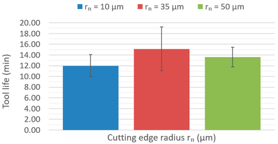
Figure 15.
The tool life with respect to the cutting edge radius size (vc = 40 m.min−1, f = 0.15 mm, ap = 1 mm).
4. Finite Element Modeling of Inconel 718 Alloy Machining
For the last two decades, finite element modelling (FEM) has been a dominant direction for studying the machinability of various materials. Currently, FEM is often used as main research tool while traditional experimental research is used to validate FEM results. The initial stage of the finite element modelling is the discretization of the geometry, which is performed by dividing the geometry into finite elements. Then, based on the qualities required for the analysis, several element types are used, such as triangular and rectangular for 2D, prismatic, tetrahedral, pyramidal, and hexagonal for 3D (Figure 16) [54].
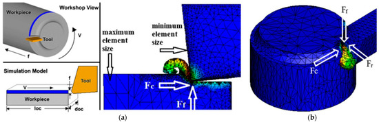
Figure 16.
Cutting system concerning the 2D (a) and 3D (b) simulations [54]. Where: v—velocity, f –feed, Fc—Cutting Force, Ff—Feed Force, Fr—Radial Force.
The latest studies in the field of studying machinability of Inconel 718 were focused on the definition of cutting speed, feed, and depth of cut influence on cutting temperature, cutting force and energy consumption, and chip morphology. Other investigations contributed to the explanation of tool geometry parameters: nose radius, inclination angle, and rake and clearance angles effect on machined surface residual stress, surface roughness, and tool wear.
Currently there are several mainstream software products which establish calculation and simulation of machining process (Figure 17).
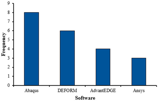
Figure 17.
Distribution of the application of programs in the simulation of turning processes of Inconel 718 superalloy (Table 6).
Numerical studies based on FEM are widely used to understand and analyze the machining process of Inconel 718 alloy. The main advantage of FEM studies is reduction of resource and time consumption needed for achieving results. However FEM results should be validated during experimental research [54]. Table 6 provides a brief analysis of articles devoted to the modeling of Inconel 718 turning processes.
Table 6.
A brief overview of the articles is devoted to the modeling of turning processes of the Inconel 718 alloy using the finite element method.
Table 6.
A brief overview of the articles is devoted to the modeling of turning processes of the Inconel 718 alloy using the finite element method.
| Reference | Tool Material/ Coating | Factors | Response | Key Conclusions |
|---|---|---|---|---|
| Moili et al. [55] | Carbide/TiN | Coolant Cutting parameters * | Cutting force Tool temperature | The influence of processing environments (cryogenic and dry) and cutting parameters on tool temperature and cutting force is studied. It has been established that cutting speed plays a critical role in heat generation. |
| Vijayaraghavan [56] | Carbide | Cutting parameters Cutting fluid concentration Inclination angle | Cutting force Energy consumption | Optimizing the inclination angle can lead to a reduction in cutting force and a reduction in power consumption. |
| Parida and Maity [57] | Carbide | Nose radius Temperature conditions (room/heated) | Cutting force Thrust force Cutting temperature Chip thickness Chip tool contact length | Heating of the machining surface of the workpiece can significantly reduce the cutting and thrust force. Increasing temperature in the workpiece–tool interface zone reduces heat generation, which decreases stress and cutting force. As the workpiece temperature and nose radius increase, the thickness of the chip decreases while tool–chip increases. |
| Shen et al. [58] | Carbide | Cutting edge microgeometry | Residual stress | An increase in the average edge radius leads to an increase in residual stress of the machined surface. |
| Veeranaath et al. [59] | SiN CBN | Cutting parameters Nose radius Insert material | Cutting force Temperature Surface roughness Tool wear Chip thickness Stress | A corner radius of 0.4 mm led to better temperature, wear, and stress performance than the 0.8 mm radius. |
| Lotfi and Amini [60] | Carbide | Ultrasonic vibration Cutting speed Feed rate | Cutting force Shear angle Chip thickness Tool temperature Tool chip engagement time | The shear angle increases when ultrasonic vibration is added to the cutting tool. Increase in cutting speed results in the increase of tool–chip engagement time when ultrasonic vibration is used. |
| Mitrofanov et al. [61] | Carbide | Ultrasonic vibration | Residual stress Temperature | Tool temperature and residual stress were lower for machining with ultrasonic vibration compared to conventional turning. |
| Uhlmann and Zettier [62] | Ceramic | Cutting speed | Cutting force Chip formation | A continuous chip is formed at cutting speeds from 100 to 200 m/min. A segmented chip is formed at speeds from 200 to 1000 m/min. Deform 2D had simulations of cutting forces closer to experimental data compared to Abaqus 2D and 3D models. |
| Paturi et al. [48] | Carbide/CVD coated | Cutting parameters | Cutting force Cutting temperature Tool wear Chip formation | Cutting force reduces with increased cutting speed because the tool–chip contact interface decreases. Cutting temperature is proportional to cutting speed, feed rate, and depth of cut. An increase in cutting temperature implies increasing strain rate, deformation effect, and high tool wear. Increasing the feed leads to an increase in the cutting temperature. Tool wear increases with increase of cutting speed and depth of cut. |
| Diaz-Alvarez et al. [63] | Carbide | Cutting speed Cutting edge angle | Cutting force Chip temperature Effective plastic strain Tool wear | The chip temperature increases with cutting speed. The increased temperature on the chip affects the wear mechanisms. Equivalent plastic strain along the cutting edge decreases slightly with cutting speed from 50 to 70 m/min and remains constant for further increments of cutting speed. |
| Nouzil et al. [64] | SIALON | Cryogenic condition Jet radius Jet location Cutting speed | Cutting force Energy consumption Cutting temperature | An increase in the radius of the jet leads to a decrease in the shear angle, which leads to an increase in the cutting force. The average cutting temperature decreases with the increasing flow of LN2 at the cutting edge. An increase in cutting speed leads to an increase in energy consumption. As the jet moves away from the cutting zone, the temperature increases with a decrease in the cutting force and vice versa. |
| Reddy et al. [65] | Carbide/TiAlN | Cutting parameters | Cutting temperature | The temperature in the cutting zone increases with an increase in the depth of cut because more material needs to be removed. Temperature increases with an increase in cutting speed, which increases friction; it is the same case with a feed rate. |
| Jangali et al. [66] | Carbide | Cutting parameters | Cutting force Tool temperature Equivalent stress | Cutting forces are primarily influenced by the depth of cut and speed, whereas cutting speed and feed have a more significant effect on tool temperature than the depth of cut. |
| Ren and Liu [67] | Feed rate Cutting speed | Residual stress Average grain size Microhardness | The combination of larger cutting speed and lower feed rate is a recommended optimized selection to obtain a better surface quality, whereas cutting speed and feed have a more significant effect on tool temperature than the depth of cut. | |
| D’Addona and Raykar [68] | Carbide/TiAlN | Cutting conditions (dry/wet) Coolant pressure | Tool temperature | The cooling pressure has a significant effect on the temperature. Greater fluid pressure allows for a reduction of the temperature. |
| Liu et al. [69] | CBN | Cutting parameters Coolant pressure | Surface roughness Cutting force | Depth of cut had the greatest effect on cutting force, while feed rate and coolant pressure had a smaller effect. The least influential factor was cutting speed. The most important factors affecting the machined surface roughness were the feed rate, followed by the coolant pressure, cutting speed, and cutting depth. |
* Cutting parameters—depth of cut, cutting speed, feed rate.
The finite element method simulates many factors, such as cutting parameters, processing environment, and cutting tool geometry. Modelling has good predictability on pair with experimental research methods. The influence of factors on cutting forces, temperature, the roughness of the machined surface, energy consumption, and tool wear can be seen. Considering the constant growth of the market of nickel superalloys and the wide range of applications, process modelling is a relatively promising method of improving the processing efficiency of Inconel 718. Modelling does not require material, machining equipment, or tool costs.
5. Conclusions
The article examines the machinability of the Inconel 718 material and analyzes the most common factors using the Pareto statistical distribution based on the processing of 69 research papers published during the period from 2004 to 2023. The influence of the cutting inserts’ material on the machining process’s characteristics, the effect of the coating of the cutting inserts on cutting parameters and stability, and the effect of coolant on cutting conditions were analyzed. The most common cutting parameters and tool geometry were analyzed when machining the Inconel 718 alloy. The following conclusions were established:
- The most common material for machining the Inconel 718 alloy is carbide, which was used uncoated in 30% of cases or with TiAlN coating (25%) for experimental studies in 75% of experimental runs. The second place with a share of 12% took PCBN. However, the effect of CNB and ceramic is still studied poorly. In the future, more attention should be paid to utilizing these tool materials in experimental studies.
- In 70% of conducted studies, machining was carried out with coated cutting inserts, though the effect of multilayer coating (Ti,Al)N + TiN coating (8%), TiAlN + AlCr2O3 coating (7%) on tool life and the machined surface is versed to be studied in feature research.
- As a cooling method when machining Inconel 718, it is advisable to use the method of minimum quantity lubrication (MQL). The variability and low lubricant consumption for this cooling method and less energy consumption make this method quite versatile.
- The analysis of cutting parameters emphasized that the most-studied range of cutting speed is 60–100 m/min (71%), which corresponds to roughing turning with coated or uncoated carbide cutting inserts, while turning in the range 140–460 m/min with using og CBN or ceramic cutting inserts in semi-finishing or finishing passes was not in the focus of most experimental studies. The same trend was noticed for feed rate and depth of cut. Feed rate in the range from 0.1 to 0.3 mm/rev was analyzed in 68% of experimental runs, however more rough (up to 0.4 mm/rev) or less rough (less than 0.08 mm/rev) were studied rarely. The mostly studied range of depth of cut is 0.2–1.1 mm (89%), while depth of cut less than 0.05 mm was studied rarely.
- During the analysis of the angles of the cutting tool, it was established that the following geometry of the cutting tool is universal when machining Inconel 718: tool cutting angle—95° (53%), clearance angle–0° (75%), rake angle—0°(55%), corner radius—0.8 mm (47%) of experimental runs. Future studies can pay more attention to chip formation mechanisms when turning by cutting insert with tool cutting angle—75°, 91°, 93°, clearance angle—6°–11°, rake angle—6°, 17°, 10°, and corner radius more than 1.2 mm.
- Finite element modelling is an efficient research tool for studying machinability of Inconel 718, which was carried out mostly in Abaques and Deform software. Though the are many studies of cutting parameters, tool geometry, and tool material on machinability of Inconel 718 the effect of coolant conditions is studied purely.
Prospective areas of future research are research into the modification of the geometry of the cutting tool and research into cooling methods, especially ecological and energy-efficient ones. It is also worth focusing on the feature study of cutting tool coatings since their use increases the tool’s life, which is critical when machining Inconel 718. Feature research in the field of finite element modeling can be focused at research of cutting insert coating and coolant parameters effect of tool life and surface quality.
Author Contributions
Conceptualization, J.P., V.K., T.V. and O.Y.; methodology, J.P. and V.K.; software, O.Y., M.K.G., D.L. and A.D.; validation, J.P., V.K. and T.V.; formal analysis, J.P. and V.K.; investigation, O.Y., M.K.G., D.L. and A.D.; resources, J.P., V.K., T.V., O.Y., M.K.G., D.L. and A.D.; data curation, V.K., T.V., O.Y., M.K.G., D.L. and A.D.; writing—original draft preparation, J.P., V.K., O.Y., T.V.; writing—review and editing, J.P., V.K., O.Y. and T.V.; visualization, J.P., V.K., O.Y., T.V., M.K.G., D.L. and A.D.; supervision, J.P. and V.K.; project administration, J.P., V.K. and T.V.; funding acquisition, J.P. and T.V. All authors have read and agreed to the published version of the manuscript.
Funding
This research was funded by research project APVV-21-0071, and VEGA 1/0266/23.
Data Availability Statement
Not applicable.
Conflicts of Interest
The authors declare no conflict of interest.
References
- De Bartolomeis, A.; Newman, S.T.; Jawahir, I.S.; Biermann, D.; Shokrani, A. Future research directions in the machining of Inconel 718. J. Mater. Process. Technol. 2021, 297, 117260. [Google Scholar] [CrossRef]
- Fu, S.H.; Dong, J.X.; Zhang, M.C.; Xie, X.S. Alloy design and development of INCONEL718 type alloy. Mater. Sci. Eng. A 2009, 499, 215–220. [Google Scholar] [CrossRef]
- Frifita, W.; Ben Salem, S.; Haddad, A.; Yallese, M.A. Optimization of machining parameters in turning of Inconel 718 Nickel-base super alloy. Mech. Ind. 2020, 21, 203. [Google Scholar] [CrossRef]
- Yin, Q.; Liu, Z.; Wang, B.; Song, Q.; Cai, Y. Recent progress of machinability and surface integrity for mechanical machining Inconel 718: A review. Int. J. Adv. Manuf. Technol. 2020, 109, 215–245. [Google Scholar] [CrossRef]
- D’Addona, D.M.; Raykar, S.J.; Narke, M.M. High Speed Machining of Inconel 718: Tool Wear and Surface Roughness Analysis. Procedia Cirp 2017, 62, 269–274. [Google Scholar] [CrossRef]
- Jeyapandiarajan, P.; Xavior, M.A.; Sasidharan, N.C.; Duchosal, A. Surface hardening and wear correlations studies when turning inconel 718. MM Sci. J. 2019, 2019, 3041–3047. [Google Scholar] [CrossRef]
- Marques, A.; Paipa Suarez, M.; Falco Sales, W.; Rocha Machado, Á. Turning of Inconel 718 with whisker-reinforced ceramic tools applying vegetable-based cutting fluid mixed with solid lubricants by MQL. J. Mater. Process. Technol. 2019, 266, 530–543. [Google Scholar] [CrossRef]
- Khanna, N.; Agrawal, C.; Dogra, M.; Pruncu, C.I. Evaluation of tool wear, energy consumption, and surface roughness during turning of inconel 718 using sustainable machining technique. J. Mater. Res. Technol. 2020, 9, 5794–5804. [Google Scholar] [CrossRef]
- Tamil Alagan, N.; Hoier, P.; Zeman, P.; Klement, U.; Beno, T.; Wretland, A. Effects of high-pressure cooling in the flank and rake faces of WC tool on the tool wear mechanism and process conditions in turning of alloy 718. Wear 2019, 434–435, 102922. [Google Scholar] [CrossRef]
- Khochtali, H.; Ayed, Y.; Zemzemi, F.; Bensalem, W. Tool wear characteristics in rough turning of Inconel 718 with coated carbide tool under conventional and high-pressure coolant supplies. Int. J. Adv. Manuf. Technol. 2021, 114, 2371–2386. [Google Scholar] [CrossRef]
- Ali, M.A.M.; Khalil, A.N.M.; Azmi, A.I.; Salleh, H.M. Optimization of Cutting Parameters for Surface Roughness under MQL, using Al2O3 Nanolubricant, during Turning of Inconel 718. In Proceedings of the International Research and Innovation Summit (IRIS), Melaka, Malaysia, 6–7 May 2017. [Google Scholar]
- Xavior, M.A.; Manohar, M.; Jeyapandiarajan, P.; Madhukar, P.M. Tool Wear Assessment during Machining of Inconel 718. Procedia Eng. 2017, 174, 1000–1008. [Google Scholar] [CrossRef]
- Capasso, S.; Paiva, J.M.; Locks Junior, E.; Settineri, L.; Yamamoto, K.; Amorim, F.L.; Torres, R.D.; Covelli, D.; Fox-Rabinovich, G.; Velduis, S.C. A novel method of assessing and predicting coated cutting tools wear during Inconel DA 718 turning. Wear 2019, 432–433, 202949. [Google Scholar] [CrossRef]
- Cantero, J.L.; Díaz-Álvarez, J.; Infante-García, D.; Rodríguez, M.; Criado, V. High speed finish turning of inconel 718 using PCBN tools under dry conditions. Metals 2018, 8, 192. [Google Scholar] [CrossRef]
- Criado, V.; Díaz-Álvarez, J.; Cantero, J.L.; Miguélez, M.H. Study of the performance of PCBN and carbide tools in finishing machining of Inconel 718 with cutting fluid at conventional pressures. Procedia Cirp 2018, 77, 634–637. [Google Scholar] [CrossRef]
- Zhao, J.; Liu, Z.; Shen, Q.; Wang, B.; Wang, Q. Investigation of cutting temperature during turning Inconel 718 with (Ti, Al)N PVD coated cemented carbide tools. Materials 2018, 11, 1281. [Google Scholar] [CrossRef]
- Jeyapandiarajan, P.; Xavior, M.A.; Anbalagan, A. Performance evaluation of (Alcrn) pvd coated cbn inserts on machining of inconel 718. MM Sci. J. 2021, 2021-November, 5219–5227. [Google Scholar] [CrossRef]
- Peterka, J.; Pokorny, P.; Vaclav, S.; Patoprsty, B.; Voyar, M. Modification of cutting tools bz deag finishing. MM Sci. J. 2020, 1, 3822–3825. [Google Scholar] [CrossRef]
- Ghiban, B.; Elefterie, C.F.; Guragata, C.; Bran, D. Requirements of Inconel 718 Alloy or Aeronautical Applications. In Proceedings of the 7th International Conference on Structural Analysis of Advanced Materials (ICSAAM), Bucharest, Romania, 19–22 September 2017. [Google Scholar]
- Jeyadurga, P.; Balamurali, S.; Aslam, M. Design of an attribute np control chart for process monitoring based on repetitive group sampling under truncated life tests. Commun. Stat. Theory Methods 2018, 47, 5934–5955. [Google Scholar] [CrossRef]
- Chu, J.; Dickin, O.; Nadarajah, S. A review of goodness of fit tests for Pareto distributions. J. Comput. Appl. Math. 2019, 361, 13–41. [Google Scholar] [CrossRef]
- Dudzinski, D.; Devillez, A.; Moufki, A.; Larrouquere, D.; Zerrouki, V.; Vigneau, J. A review of developments towards dry and high speed machining of Inconel 718 alloy. Int. J. Mach. Tools Manuf. 2004, 44, 439–456. [Google Scholar] [CrossRef]
- Díaz-álvarez, J.; Criado, V.; Miguélez, H.; Luis Cantero, J. PCBN performance in high speed finishing turning of inconel 718. Metals 2018, 8, 582. [Google Scholar] [CrossRef]
- Hongjun, Z.; Jianguang, L.; Zhaopeng, H. Wear Mechanism of Cemented Carbide Tool and Modeling Tool Wear in Machining Inconel 718. IOP Conf. Ser. Mater. Sci. Eng. 2020, 780, 052024. [Google Scholar] [CrossRef]
- Dong, D.; Li, T.; Wang, X.; Qiao, Y.; Guo, P. Tool wear mechanism of turning Inconel 718 and EEMD-based feature analysis. J. Phys. Conf. Ser. 2021, 012085. [Google Scholar] [CrossRef]
- Jadam, T.; Datta, S.; Masanta, M. Wear morphology of microwave post-treated WC-Co tool during machining of Inconel 718 superalloy. Mater. Today Proc. 2020, 38, 2133–2139. [Google Scholar] [CrossRef]
- Zou, Z.; He, L.; Jiang, H.; Yuan, S.; Ren, Z. Influence of microgroove structure on cutting performance and chip morphology during the turning of superalloy Inconel 718. Materials 2021, 14, 4142. [Google Scholar] [CrossRef]
- Sugihara, T.; Tanaka, H.; Enomoto, T. Development of Novel CBN Cutting Tool for High Speed Machining of Inconel 718 Focusing on Coolant Behaviors. Procedia Manuf. 2017, 10, 436–442. [Google Scholar] [CrossRef]
- Sugihara, T.; Nishimoto, Y.; Enomoto, T. Development of a novel cubic boron nitride cutting tool with a textured flank face for high-speed machining of Inconel 718. Precis. Eng.-J. Int. Soc. Precis. Eng. Nanotechnol. 2017, 48, 75–82. [Google Scholar] [CrossRef]
- Costes, J.P.; Guillet, Y.; Poulachon, G.; Dessoly, M. Tool-life and wear mechanisms of CBN tools in machining of Inconel 718. Int. J. Mach. Tools Manuf. 2007, 47, 1081–1087. [Google Scholar] [CrossRef]
- Jadam, T.; Datta, S.; Masanta, M. Influence of cutting tool material on machinability of Inconel 718 superalloy. Mach. Sci. Technol. 2021, 25, 349–397. [Google Scholar] [CrossRef]
- Shalaby, M.A.; Veldhuis, S.C. Tool wear and chip formation during dry high speed turning of direct aged Inconel 718 aerospace superalloy using different ceramic tools. Proc. Inst. Mech. Eng. Part J J. Eng. Tribol. 2019, 233, 1127–1136. [Google Scholar] [CrossRef]
- Bushlya, V.; Zhou, J.; Stahl, J.E. Effect of Cutting Conditions on Machinability of Superalloy Inconel 718 During High Speed Turning with Coated and Uncoated PCBN Tools. Procedia Cirp 2012, 3, 370–375. [Google Scholar] [CrossRef]
- Khan, S.A.; Soo, S.L.; Aspinwall, D.K.; Sage, C.; Harden, P.; Fleming, M.; White, A.; M’Saoubi, R. Tool wear/life evaluation when finish turning Inconel 718 using PCBN tooling. Procedia Cirp 2012, 1, 283–288. [Google Scholar] [CrossRef]
- Zeilmann, R.P.; Fontanive, F.; Soares, R.M. Wear mechanisms during dry and wet turning of Inconel 718 with ceramic tools. Int. J. Adv. Manuf. Technol. 2017, 92, 2705–2714. [Google Scholar] [CrossRef]
- Gürgen, S.; Tali, D.; Kushan, M.C. An investigation on surface roughness and tool wear in turning operation of inconel 718. J. Aerosp. Technol. Manag. 2019, 11, e1319. [Google Scholar] [CrossRef]
- Bouzakis, K.D.; Michailidis, N.; Skordaris, G.; Bouzakis, E.; Biermann, D.; M’Saoubi, R. Cutting with coated tools: Coating technologies, characterization methods and performance optimization. Cirp Ann.-Manuf. Technol. 2012, 61, 703–723. [Google Scholar] [CrossRef]
- Deng, Y.; Chen, W.L.; Li, B.X.; Wang, C.Y.; Kuang, T.C.; Li, Y.Q. Physical vapor deposition technology for coated cutting tools: A review. Ceram. Int. 2020, 46, 18373–18390. [Google Scholar] [CrossRef]
- Zhao, J.; Liu, Z. Influences of coating thickness on cutting temperature for dry hard turning Inconel 718 with PVD TiAlN coated carbide tools in initial tool wear stage. J. Manuf. Process. 2020, 56, 1155–1165. [Google Scholar] [CrossRef]
- Sharma, V.S.; Dogra, M.; Suri, N.M. Cooling techniques for improved productivity in turning. Int. J. Mach. Tools Manuf. 2009, 49, 435–453. [Google Scholar] [CrossRef]
- Çakıroğlu, R. Machinability Analysis of Inconel 718 Superalloy with AlTiN-Coated Carbide Tool Under Different Cutting Environments. Arab. J. Sci. Eng. 2021, 46, 8055–8073. [Google Scholar] [CrossRef]
- Chaabani, S.; Arrazola, P.J.; Ayed, Y.; Madariaga, A.; Tidu, A.; Germain, G. Comparison between cryogenic coolants effect on tool wear and surface integrity in finishing turning of Inconel 718. J. Mater. Process. Technol. 2020, 285, 116780. [Google Scholar] [CrossRef]
- Mou, W.; Zhu, S. Vibration, tool wear and surface roughness characteristics in turning of Inconel 718 alloy with ceramic insert under LN2 machining. J. Braz. Soc. Mech. Sci. Eng. 2020, 42, 369. [Google Scholar] [CrossRef]
- Hoier, P.; Klement, U.; Tamil Alagan, N.; Beno, T.; Wretland, A. Characterization of tool wear when machining alloy 718 with high-pressure cooling using conventional and surface-modified WC–Co tools. J. Superhard Mater. 2017, 39, 178–185. [Google Scholar] [CrossRef]
- Mane, P.A.; Kallol, A.N.; Doiphode, R.L.; Manjunath, G.A.; Saleh, B.; Abbas, M.; Saleel, C.A.; Alarifi, I.M. Inconel 718 Turning Process Parameters Optimization with MQL Nanofluid Based on CuO Nanoparticles. J. Nanomater. 2022, 2022, 1408529. [Google Scholar] [CrossRef]
- Pinheiro, C.; Kondo, M.Y.; Amaral, S.S.; Callisaya, E.S.; De Souza, J.V.C.; Alves, M.C.D.; Ribeiro, M.V. Effect of machining parameters on turning process of Inconel 718. Mater. Manuf. Process. 2021, 36, 1421–1437. [Google Scholar] [CrossRef]
- Rakesh, M.; Datta, S. Machining of Inconel 718 Using Coated WC Tool: Effects of Cutting Speed on Chip Morphology and Mechanisms of Tool Wear. Arab. J. Sci. Eng. 2020, 45, 797–816. [Google Scholar] [CrossRef]
- Paturi, U.M.R.; Methuku, S.; Siripragada, S.S.; Sangishetty, Y.; Gunda, R.K. Finite element simulations of machinability parameters in turning of Inconel 718. Mater. Today Proc. 2020, 38, 2658–2663. [Google Scholar] [CrossRef]
- Xu, D.; Ding, L.; Liu, Y.; Zhou, J.; Liao, Z. Investigation of the influence of tool rake angles on machining of inconel 718. J. Manuf. Mater. Process. 2021, 5, 100. [Google Scholar] [CrossRef]
- Arunachalam, R.M.; Mannan, M.A.; Spowage, A.C. Surface integrity when machining age hardened Inconel 718 with coated carbide cutting tools. Int. J. Mach. Tools Manuf. 2004, 44, 1481–1491. [Google Scholar] [CrossRef]
- Coelho, R.T.; Silva, L.R.; Braghini, A.; Bezerra, A.A. Some effects of cutting edge preparation and geometric modifications when turning INCONEL 718 (TM) at high cutting speeds. J. Mater. Process. Technol. 2004, 148, 147–153. [Google Scholar] [CrossRef]
- Zhuang, K.; Hu, C.; Zhou, J.; Lin Peng, R. Investigation on work hardening phenomenon in turning Inconel 718 with chamfered inserts considering thermal-mechanical loads. Procedia Cirp 2020, 87, 47–52. [Google Scholar] [CrossRef]
- Vopat, T.; Straka, R.; Kuruc, M.; Peterka, J. The Effect of Cutting Edge Radius Sizes on Tool Life in Machining Nickel Alloy Inconel 718. Ann. DAAAM Proc. Int. DAAAM Symp. 2022, 33, 180–187. [Google Scholar] [CrossRef]
- Korkmaz, M.E.; Gupta, M.K. A State of the Art on Simulation and Modelling Methods in Machining: Future Prospects and Challenges. Arch. Comput. Methods Eng. 2023, 30, 161–189. [Google Scholar] [CrossRef]
- Mouli, G.C.; Marimuthu, K.P.; Jagadeesha, T. 2d finite element analysis of inconel 718 under turning processes. In Proceedings of the 3rd International Conference on Advances in Mechanical Engineering (ICAME)/1st International Conference on Recent Advances in Composite Materials (ICRACM), SRM Inst Sci & Technol, Chennai, India, 24–29 February 2020. [Google Scholar]
- Vijayaraghavan, V.; Garg, A.; Gao, L.; Vijayaraghavan, R.; Lu, G.X. A finite element based data analytics approach for modeling turning process of Inconel 718 alloys. J. Clean. Prod. 2016, 137, 1619–1627. [Google Scholar] [CrossRef]
- Parida, A.K.; Maity, K. Effect of nose radius on forces, and process parameters in hot machining of Inconel 718 using finite element analysis. Eng. Sci. Technol.-Int. J.-Jestech 2017, 20, 687–693. [Google Scholar] [CrossRef]
- Shen, Q.; Liu, Z.Q.; Hua, Y.; Zhao, J.F.; Lv, W.Y.; Mohsan, A.U.H. Effects of Cutting Edge Microgeometry on Residual Stress in Orthogonal Cutting of Inconel 718 by FEM. Materials 2018, 11, 1015. [Google Scholar] [CrossRef] [PubMed]
- Veeranaath, V.; Anshuman, A.; Sethia, S. Experimental Study and Finite Element Analysis of the Impact of Tool Edge Geometry in Orthogonal Machining of Super Alloy Inconel 718. In Proceedings of the 3rd International Conference on Advances in Mechanical Engineering (ICAME)/1st International Conference on Recent Advances in Composite Materials (ICRACM), SRM Inst Sci & Technol, Chennai, India, 24–29 February 2020; Volume 912, p. 032032. [Google Scholar]
- Lotfi, M.; Amini, S. FE simulation of linear and elliptical ultrasonic vibrations in turning of Inconel 718. Inst. Mech. Eng. Part E-J. Process Mech. Eng. 2018, 232, 438–448. [Google Scholar] [CrossRef]
- Mitrofanov, A.V.; Babitsky, V.I.; Silberschmidt, V.V. Finite element analysis of ultrasonically assisted turning of Inconel 718. J. Mater. Process. Technol. 2004, 153, 233–239. [Google Scholar] [CrossRef]
- Uhlmann, E.; von der Schulenburg, M.G.; Zettier, R. Finite element modeling and cutting simulation of Inconel 718. Cirp Ann.-Manuf. Technol. 2007, 56, 61–64. [Google Scholar] [CrossRef]
- Diaz-Alvarez, J.; Cantero, J.L.; Miguelez, H.; Soldani, X. Numerical analysis of thermomechanical phenomena influencing tool wear in finishing turning of Inconel 718. Int. J. Mech. Sci. 2014, 82, 161–169. [Google Scholar] [CrossRef]
- Nouzil, I.; Pervaiz, S.; Kannan, S. Role of jet radius and jet location in cryogenic machining of Inconel 718: A finite element method based approach. Int. J. Interact. Des. Manuf.-Ijidem 2021, 15, 1–19. [Google Scholar] [CrossRef]
- Reddy, S.R.; Kumar, M.S.; Vasu, V. Temperature study in Turning Inconel-718: 3D Simulation and Experimentation. Mater. Today-Proc. 2017, 4, 9946–9950. [Google Scholar] [CrossRef]
- Jangali, S.G.; Gaitonde, V.N.; Kulkarni, V.N.; Madhusudhana, H.K. Analyzing the effect of cutting parameters on forces and tool-tip temperature in turning of nickel-based superalloy using FE simulation. Mater. Today-Proc. 2022, 49, 1833–1843. [Google Scholar] [CrossRef]
- Ren, X.P.; Liu, Z.Q. A simulation model for predicting surface integrity coupled thermal-mechanical effect in turning of Inconel 718 super alloy. Int. J. Adv. Manuf. Technol. 2019, 100, 1825–1837. [Google Scholar] [CrossRef]
- D’Addona, D.M.; Raykar, S.J. Thermal Modeling of Tool Temperature Distribution during High Pressure Coolant Assisted Turning of Inconel 718. Materials 2019, 12, 408. [Google Scholar] [CrossRef] [PubMed]
- Liu, L.; Wu, M.Y.; Li, L.B.; Cheng, Y.N. FEM Simulation and Experiment of High-Pressure Cooling Effect on Cutting Force and Machined Surface Quality during Turning Inconel 718. Integr. Ferroelectr. 2020, 206, 160–172. [Google Scholar] [CrossRef]


Disclaimer/Publisher’s Note: The statements, opinions and data contained in all publications are solely those of the individual author(s) and contributor(s) and not of MDPI and/or the editor(s). MDPI and/or the editor(s) disclaim responsibility for any injury to people or property resulting from any ideas, methods, instructions or products referred to in the content. |
© 2023 by the authors. Licensee MDPI, Basel, Switzerland. This article is an open access article distributed under the terms and conditions of the Creative Commons Attribution (CC BY) license (https://creativecommons.org/licenses/by/4.0/).