Abstract
An experimental investigation is performed on various cold-formed profiled sheets to study the connection behavior of composite deck slab actions using bolted shear connectors. Various profiles like dovetailed (or) re-entrant profiles, rectangular profiles and trapezoidal profiles are used in the present investigation. This experimental investigation deals with the evaluation of various parameters such as the ultimate load carrying capacity versus deflection, load versus slip, ductility ratio, strain energy and modes of failure in composite slab specimens with varying profiles. From the test results the performance of dovetailed profiled composite slabs’ resistance is significantly higher than the other two profiled composite deck slabs.
1. Introduction
Composite construction is gaining more importance all over the world due to the effective utilization of concrete and steel. Composite deck slabs consist of profiled steel sheeting below and concrete block on top of the profiled sheet. The composite construction consists of composite beams, composite columns and composite deck slabs. The cold-formed profiled sheet used in composite slab systems performs two important functions. It acts as a formwork while casting concrete and it works as a substitute for the main steel life-time tension reinforcement. In order to prevent the shrinkage and temperature effects, an additional secondary reinforcement is provided. The idea behind cold-formed profiled steel members is to use light weight elements rather than heavy weight elements to carry the same load. Cold-formed profiled composite slabs have greater strength to weight ratios when compared with traditional concrete slabs. The cold-formed steel sheet is rolled into a specific profile or shape to increase its cross-sectional area. Hence it provides high resistance in composite slab systems. Furthermore, according to Matthew and Oehlers [1] it is clear that the steel sheet/concrete interface is subjected to longitudinal shear stress due to the weight of concrete placed above the steel sheet. Due to the longitudinal shear transfer of loads, stress is developed at the supports. To overcome the stress at the supports, bolted shear connectors or embossment are implemented. The longitudinal shears were mainly transferred across the cold-formed steel sheet and concrete interface by friction. To evaluate cross sectional area and the friction property at the sheet/concrete interface, different generic types of profile ribs are experimentally investigated. Hence using cold formed profiled steel sheet becomes very important in the composite slab construction and therefore many researchers have carried out investigations. The effects of profiles of various types using cold-formed sheets are developed for the composite slab construction.
2. Literature Review
The performance of composite deck slabs is similar to traditional reinforced concrete (RC) slabs, but the main difference lies in the fact that, in composite slabs the profiled steel sheet is effectively utilized with higher significant cross-sectional area. The design load being the same for conventional RC slabs and composite slabs, the bending stresses on the profiled steel sheeting in composite deck slabs were low due to the high moment of inertia. Hence composite slabs were capable of carrying higher load when compared to conventional RC slabs. Furthermore, the high load carrying capacity of composite slabs has been justified from the literature mentioned below. Profiled steel sheet decking has low-ductility and high strength which is a relatively new trend in the construction sector. The strength of such decking is evaluated under combined flexure, web crippling and moment-rotation capability in order to use such type of profiled steel sheet decking in an economic way. Akhand et al. [2] conducted experiments on the dovetailed or re-entrant profiles, using cold-formed sheeting (Bondek-II sheeting) of nominal thickness 1.0 mm. It is noticed from the test results that such kind of decking displayed high buckling sensitivity. The failure of the deck is caused by the yield of the profile ribs. After reaching the ultimate load the profiled steel sheet started to delaminate from the concrete which reduces the load gradually on the profiled steel sheeting until load failure. The profile sheeting will fail due to yielding after reaching its maximum load. Hence profiled steel sheet decking has low-ductility, high strength and high load carrying capacity.
Hyeong Yeol Kim and Youn Ju Jeong [3] proposed a new type of bridge girder with longer and light-weight span when compared with conventional RC deck slabs. An experimental investigation was carried out on the full-scale composite deck slabs with a size of 3700 mm × 1000 mm and they were compared with conventional RC decks of the same size. The proposed neutral axis of the deck systems were approximately located at half their depth, while comparing the neutral axis, traditional RC deck slabs were two-thirds of their depth. Compared to the RC deck slabs, the flexural rigidity of the composite deck slabs is approximately twice as high. Two and a half times more load was borne by the composite deck slabs than by the traditional RC deck slabs. Wright et al. [4] states that load deflection response of the composite deck slabs with steel sheet follows a linear elastic path until the profiled steel sheet starts to buckle. Once buckling is started, the load deflection response follows a non-linear path. In the elastic state the profile starts yielding. Hence the load carrying response of the composite slabs is high compared to conventional RC deck slabs.
Baskar and Antony Jeyasehar [5] stated that the composite behavior between concrete slabs and the profiled steel sheet can be increased by providing frictional and mechanical interlocking in the profiled steel sheet. The shear in the composite slabs is transferred longitudinally via interlocking devices. Such an interlocking system provides higher interaction between the steel and the concrete. Bashar et al. [6] investigated the palm oil clinker aggregates (POC) as a full replacement for normal aggregates to produce lightweight concrete. Eight full scale composite-slab specimens were cast, of which six were made of palm oil clinker concrete (POCC) and two were made of traditional concrete. Trapezoidal profiled sheets (LYSAGHT BONDEK-II) of 1 mm thickness were used in the composite slabs with the scale of the specimen being 2700 mm × 600 mm × 125 mm, the cross-sectional area (Ap) was 980 mm2 and the yield strength (fyp) is 550 N/mm2. Above the ribs (hc), the thickness of the concrete was 71 mm. Two shear spans were used with short shear spans of 450 mm and long shear spans of 900 mm. It is therefore inferred from the test results that POCC were suitable to be used for structural applications with a weight reduction of 18.3% compared to traditional concrete composite slabs.
Prajapati et al. [7] investigated composite deck slab behavior with trapezoidal profiled stainless steel decking sheets. The slabs of size 1000 mm × 400 mm × 90 mm were cast with trapezoidal profiled stainless-steel sheets of 1 mm thickness at the bottom. Bolted shear connectors 15 mm diameter × 55 mm length were used for connection. Two sets of specimens, one with a short shear span of 135 mm and the other set with a longer shear span of 300 mm were made. Failure load was attained at a maximum of 68 kN with 135 mm shear span and a corresponding maximum mid span deflection of 12.28 mm was noticed. The load at first crack was 57.14 kN which is 84% of the failure load. Shorter shear span specimens failed in shear bond mode while longer shear span specimens failed in flexure mode. Shiming Chen and Xiaoyu Shi [8] used dovetailed (738 × 1800 mm) and trapezoidal profile sheets (914 mm × 2600 mm) under the commercial name Holorib-2000 sheets and 3D-DECK sheets, respectively. The results from the bending test obtained by Redzuan Abdullah and Samuel Easterling W. [9] and Chen S. [10] are taken for finite element (FE) validation. Eldib M.E et al. [11], using the contact mechanism between concrete and steel due to the profiled sheet form, further developed a new finite element model including profile shapes and concrete crushing failure. Cohesion of 0.06 MPa and 0.08 MPa is adopted for trapezoidal and dovetailed specimens and a friction coefficient of 0.3 is adopted for both the type of slabs. From FE analysis, it appears that the mid span deflection is spanned by 250 and 50, respectively. From the edge to the middle of the span, the slips are reduced and the highest slips occur at the end of the sample. The ratio of capacity carrying experimental load to capacity carrying analytical load (P test/PFE) value is found to be around 100% varying 0.84 to 1.13. Slips and deflections obtained by FE agreed with similar values obtained from experimental results. The FE research focusing on the interface contact model agrees well with the test results when comparing the experimental and FE analytical results. Finally, the performance and load carrying capacity of composite deck slabs were predicted.
Namdeo Adkuji Hedaoo et al. [12] used trapezoidal profiled galvanized iron sheets of 0.8 mm thickness. Eighteen slab specimens (3000 mm × 830 mm × 102 mm) were cast. The depth of profiled sheets (hp) were 52 mm and the thickness of concrete above sheeting (hc) was 50 mm. Static and cyclic loads were applied on simply supported slabs in order to assess the structural behavior and loading capacity of the composite system. The preliminary cycling loading initiated the failure of chemical bonds (due to adhesive) formed between concrete and steel profiles. Later, mechanical bond (due to embossments) failure occurred due to static load applied after the application of cyclic load. Marimuthu et al., Ikhlas et al. and Saddam et al. [13] studied the behavior of composite deck slabs using embossed trapezoidal profiled sheets to evaluate the m-k values. The experimental results were compared with European Standards EN [14] and British Standards BS [15] for the partial interaction design methods. It was concluded from the experimental results that insufficient bonding between the concrete and profile steel sheet can be enhanced by providing stud connectors, different embossing details and increasing the concrete portion depth. Baskar [16] studied the stud shear connectors’ behavior which increase the ultimate strength and ductility in the composite deck system. The deck slabs with and without embossment sheets are cast and tested. It is found that composite slabs without embossments tend to delaminate earlier than the embossed profile with stud shear connectors. The load carrying capacities were increased by including embossment and shear stud connectors in the profile sheet. Lakshmikandhan et al. [17] investigated three different shear transferring mechanisms to improve bond strength, in which indentation embossment and fastening studs were used for the study. Due to the mechanical shear connectors provided in the composite deck slabs, strength, stiffness, flexural capacity and load carrying capacity increased. The shear stud connectors proved to effectively transfer the load.
The present investigation mainly focused on three different profiled steel sheets viz., trapezoidal profile, rectangular profile and dovetailed profile under static flexural loading conditions. To determine the ultimate load carrying capacity of the composite deck slabs, maximum deflection, end slips and strain energy capability of the specimen were investigated.
3. Preliminary Investigation
3.1. Concrete Properties
The procurement of materials, sample test, materials properties and mix design calculation were done in accordance with IS (Indian Standard) Code [18,19,20,21]. The experimental results are shown in the Table 1.

Table 1.
Properties of concrete.
3.2. Profiled Steel Sheeting Properties
Cold-formed sheets of 1 mm thick steel were bought from the market. Through the press breaking process, it was then rendered into the appropriate profile form. The profile sheets have a length and width of 1600 mm and 750 mm, respectively. Between the different profiles, the cross-sectional area and its moment of inertia varies. In order to assess the structural properties, coupon tests were performed on the cold-formed steel sheet. Table 2 tabulates the test results of the mechanical properties of the steel sheet.
Table 2.
Mechanical properties steel sheet.
Geometric Variation of Profiles of Steel Sheeting
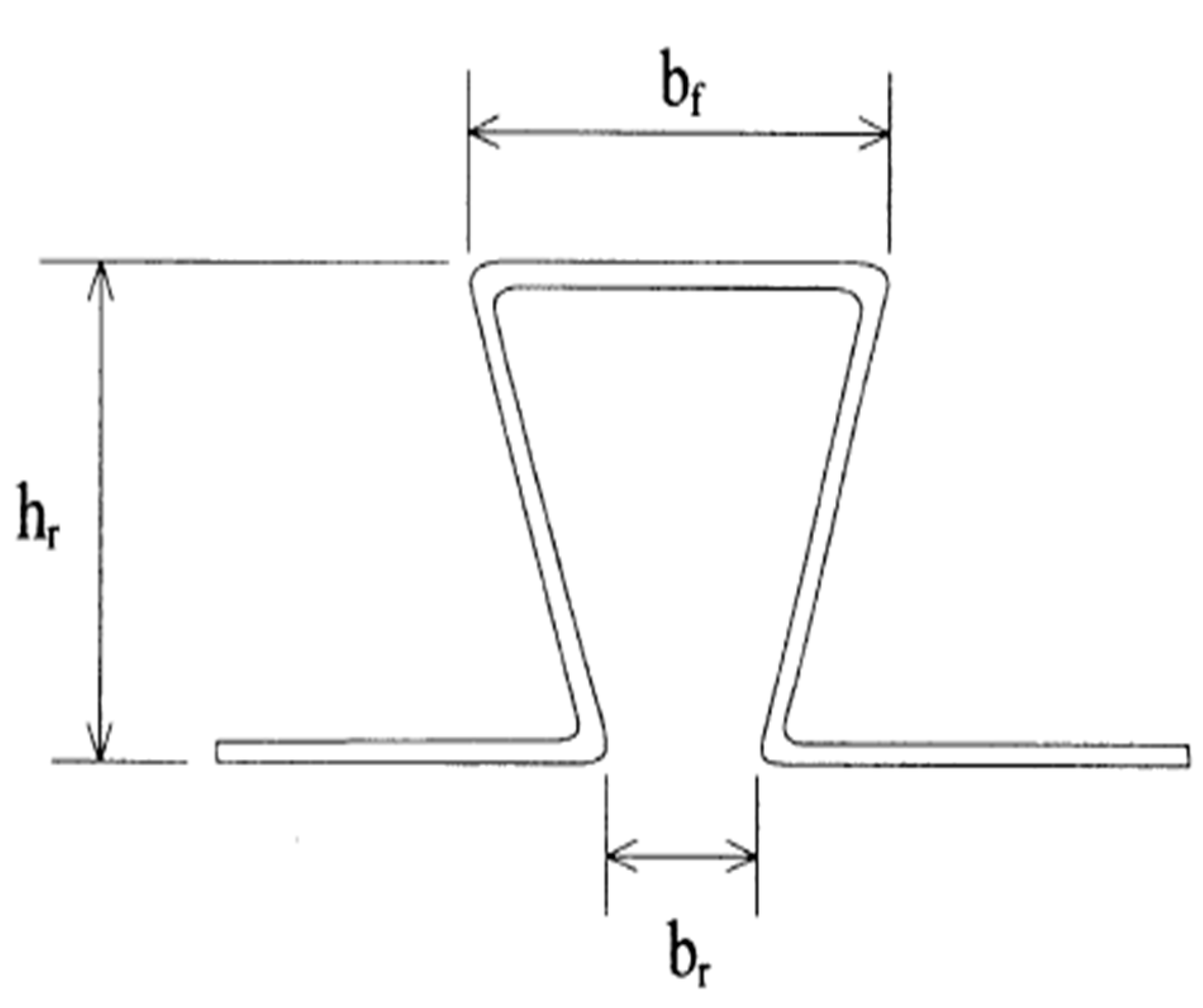
The geometrical shape of the rib used for choosing the specimens is shown below in Figure 1.
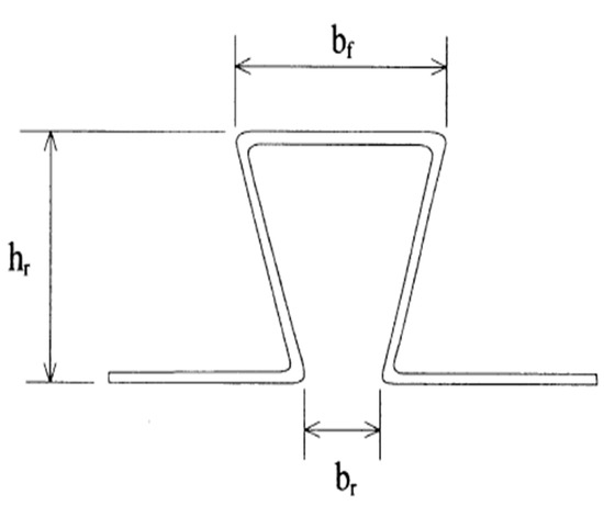
Figure 1.
Generic shape of the profiled sheet rib. hr—height of rib, bf—width of flange, and br—width opening of ribs.
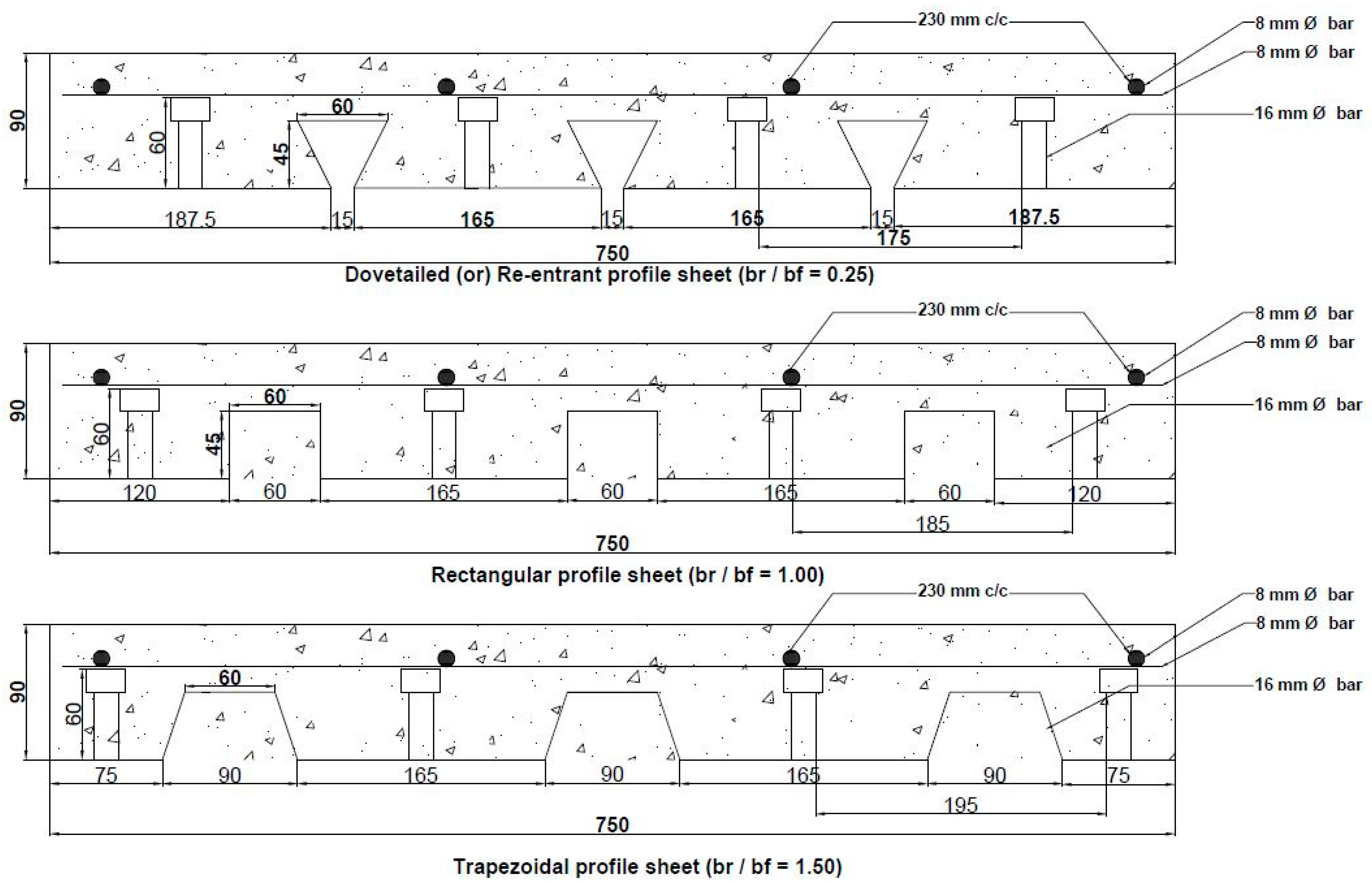
The variation in the generic profile of the sheet is obtained by varying the br/bf ratio. By varying the br/bf ratio the profile can be transformed from dovetailed profile or rectangular profile or trapezoidal profile. Figure 2 shows the various profiles adopted and their corresponding cross-sectional dimensions. Burnet and Oehlers investigated the parameters affecting the mechanical bond characteristics using a new form of push out test with different rib shear connectors. They proposed a new design procedure with different profiled geometry with embossments, profile thickness and cross section area of composite deck slabs. The geometric properties of profiled sheeting are tabulated in Table 3.
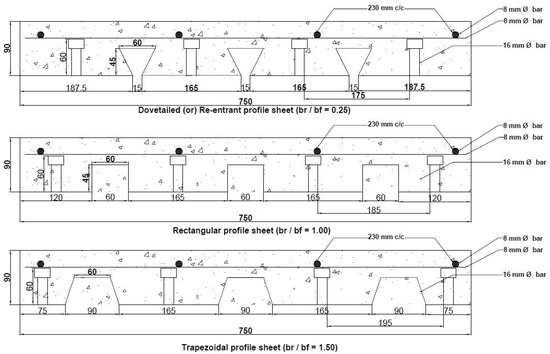
Figure 2.
Cross sectional dimensions of profiled sheet.
Table 3.
Geometric properties of profiled sheeting.
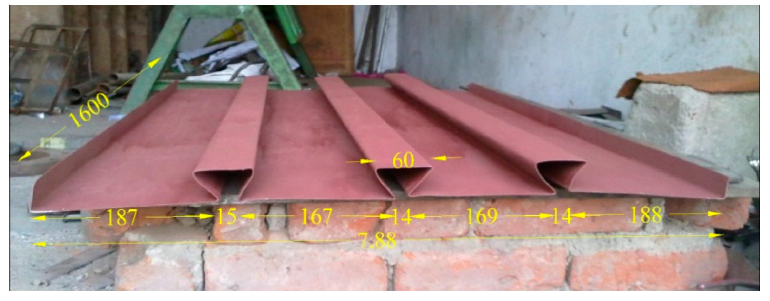
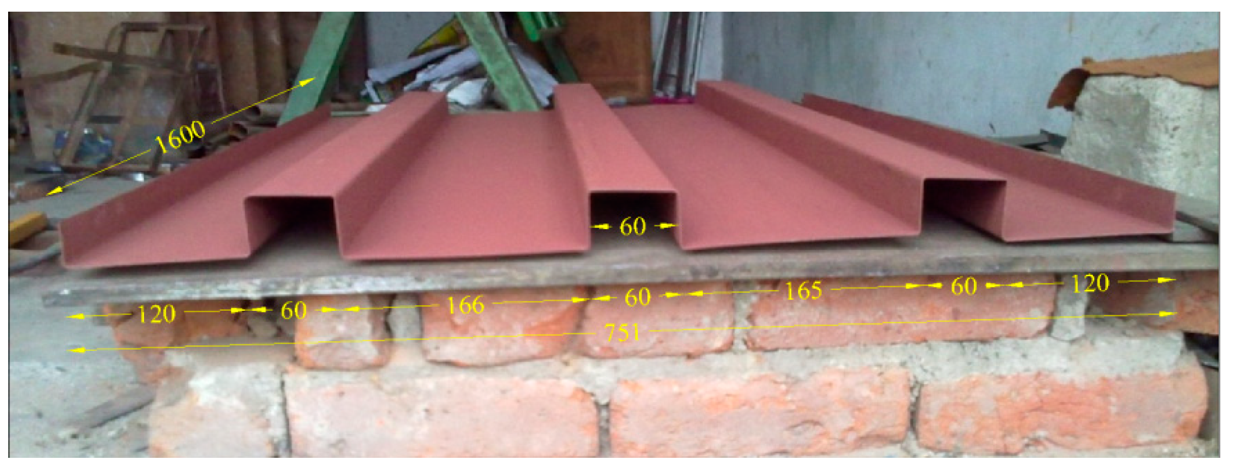
Figure 3, Figure 4 and Figure 5 show the fabricated specimens of dovetailed, rectangular and trapezoidal profiles, respectively, adopted for the present studies. The actual dimensions of the fabricated profiled sheets are measured and compared with that of the ideal one. It is found that the dimensions varied in the maximum range of ±2%.
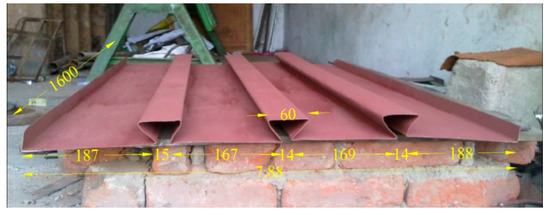
Figure 3.
Dovetailed or re-entrant profiled sheet (All dimensions are in mm).

Figure 4.
Rectangular profiled sheet (All dimensions are in mm).
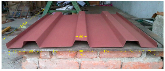
Figure 5.
Trapezoidal profiled sheet (All dimensions are in mm).
3.3. Shear Connector
Initially there will be a bond between the concrete and reinforcement in the reinforced concrete section. In the composite section the bond between the concrete and steel sheets were insufficient. This loss of bond is generally counteracted by the provision of shear connectors in between concrete core and profiled steel sheeting. In this study, bolted shear connectors of 16 mm diameter and 60 mm length are used. The shear connectors are provided at each end as end shear connectors. The end shear connectors are the main parameter responsible for the end slip resistance. The end anchorages are bolted 50 mm from the edge of the steel sheet. Furthermore, the shear connectors are bolted 360 mm away from the end anchorages.
3.4. Mild Steel Bars
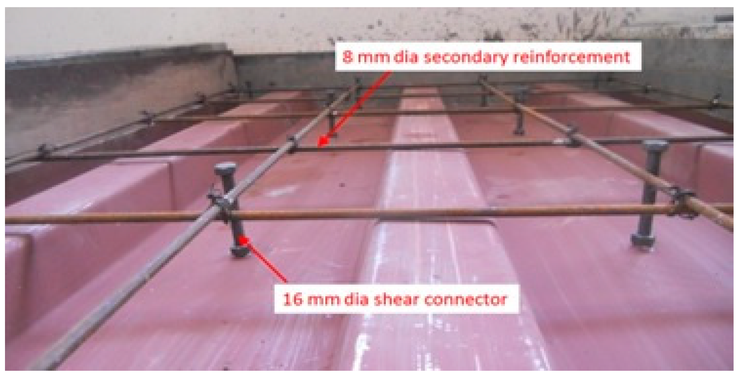
The use of cold-formed profiled sheet in composite slabs performs the function of acting as tension reinforcement. To counteract the shrinkage and temperature effect, a minimum reinforcement was provided. In this study, mild steel reinforcement of 8 mm diameter spaced apart at 230 mm is used in both directions. Figure 6 shows the arrangement of bolted shear connectors on a profiled sheet and the arrangement of mild steel reinforcement.
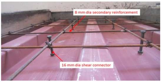
Figure 6.
Cold-formed sheet with bolted shear connectors and mild steel reinforcement.
4. Experimental Studies on Composite Slab
4.1. Preparation of Composite Slab Specimens
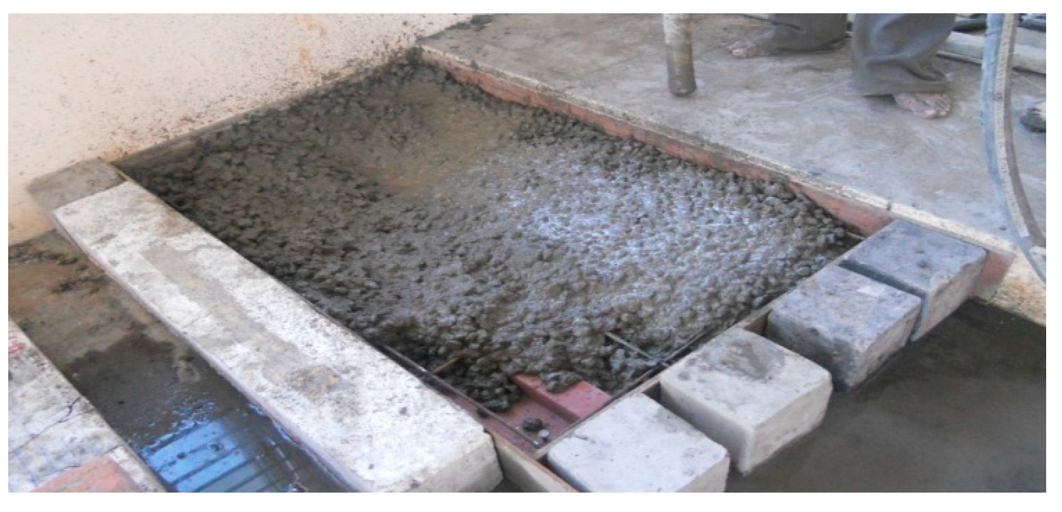
A total of 6 composite slab specimens (two specimens for each profile) were considered with depth of 90 mm (ht), width of 750 mm (b) and span of 1600 mm (L), respectively. The concrete thicknesses above the flange (hc) were 45 mm, while the height of profiled steel deck/height of rib (hr) was 45 mm deep. The composite slab specimens were cast with the profiled sheet at the base while the sides were supported by wooden planks as shown in Figure 7. The sheets were thoroughly cleaned before concreting. Bolted shear connectors were fastened in the holes provided in the sheet. To control shrinkage and temperature cracks, 8 mm Ø re-bar with c/c of 230 mm were placed in both directions. These bars were positioned on the top of the profiled sheet ribs. All the slabs were cast and cured for 28 days using M25 grade concrete. After 28 days, the composite deck slabs were whitewashed and transferred using appropriate supports from the casting yard to the laboratory to prevent the flexural loads occurred during the transfer.
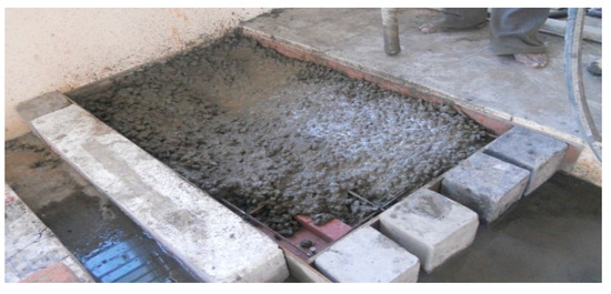
Figure 7.
Casting of specimen.
4.2. Experimental Set Up for Flexural Strength Test of Composite Slab Specimens
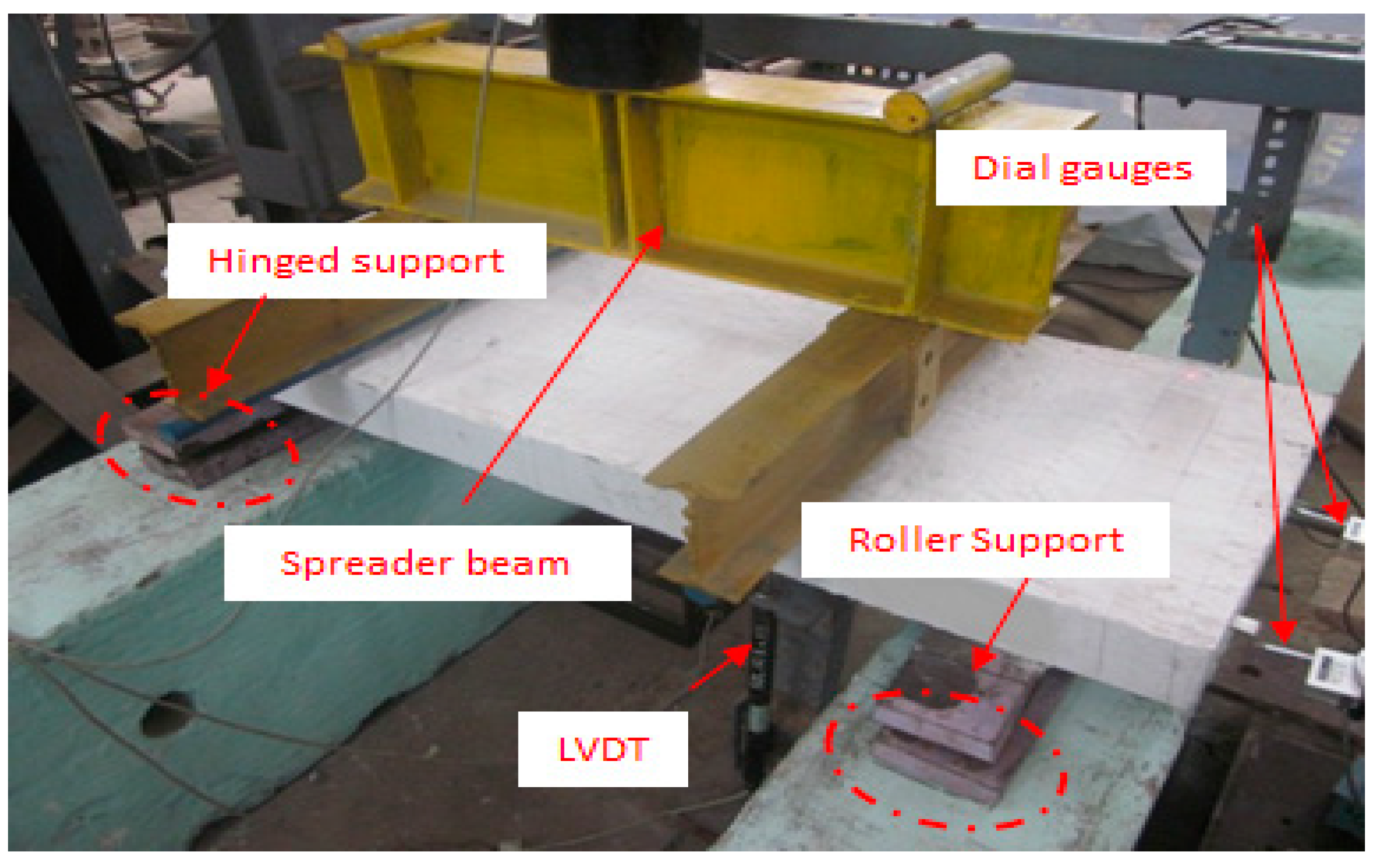
The experimental set up and schematic view of composite deck slabs specimens is shown in Figure 8 and Figure 9. Using a loading frame of capacity 250 kN, the load is applied monotonically on the specimen using a hydraulic jack. The specimens are simply supported at both ends for an effective span (Le) of 1400 mm. The overhanging distance for each support (Lo) is 100 mm and the distance between loading point from the center of support (Ls) is 300 mm. Loads were used to measure the load carried by the specimen with the help of load cells and relative deflections were measured using two linearly variable differential transducers (LVDT) placed at the mid span and at the distance of one-quarter of the span from one end. The rate of loading was 0.1 mm/s and the readings were automatically recorded in specific load intervals of 5 kN until the specimen failed. The composite deck slabs were supported on a roller support and the other side by a hinged support. Digital dial gauges were placed on both sides to measure the slips between the steel and the concrete.
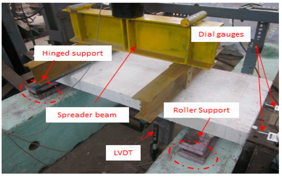
Figure 8.
Experimental setup for flexural strength test of composite slab specimens.
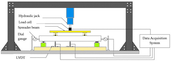
Figure 9.
Schematic view.
5. Results and Discussions
5.1. Ultimate Load Carrying Capacity
The ultimate load carried by the composite deck slabs specimens are tabulated below in the Table 4.
Table 4.
Test results of composite deck slabs.
An experimental test result shows that trial I dovetailed, or a re-entrant, profiled composite slab has the maximum load carrying capacity of 93.5 kN when compared to the other profiles. Trial II trapezoidal profiled composite slabs have the lowest carrying capacity of 65.5 kN. In trial II dovetailed, or re-entrant, profiled composite slabs, initial cracking developed at 53.2 kN load whereas initial cracking occurred at 45 kN for trial I rectangular profiled composite slabs and 44 kN for trial II trapezoidal profiled composite slabs. Initial cracking for all the types of profiles were found at the middle of the composite deck slabs on top of the profiled steel sheet. Furthermore, initial cracking occurred at 50–75% of the ultimate load.
5.2. Deflection
Deflections were noted at mid span at the central trough of the profiled sheeting by using a linear variable differential transducer (LVDT). Figure 10 shows the load versus deflection curve of dovetailed, or re-entrant; rectangular and trapezoidal profiled composite slabs of trial I and trial II.
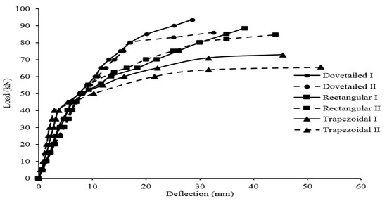
Figure 10.
Load versus deflection curve of profiled composite slabs for trials I and II.
A linear elastic path follows the load-deflection behavior of all the profile shapes until the steel sheet starts to buckle; after that, non-linear load-deflection behavior accompanied by material yield resulted in this. Therefore, the ultimate strength is much greater than the strength at the first buckle, and several profiles are built in the non-linear part of the load carrying range to carry working loads. From the graph, it is obvious that dovetailed, or re-entrant, profiled slabs carried maximum loads of 93.5 kN while the deflection was 28.53 mm which was minimum when compared to other profiles like trapezoidal and rectangular profiled slabs.
5.3. End Slip
The relative horizontal displacement between concrete slabs and the profiled steel sheeting was defined as slips, which is measured using dial gauges. Figure 11 indicates end slips of rectangular profiled composite slabs.
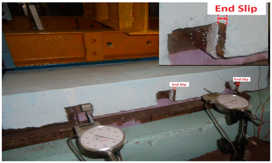
Figure 11.
Slip of rectangular profiled composite slab.
Figure 12 shows the load versus slip curve of dovetailed, or re-entrant; rectangular and trapezoidal profiled composite slabs of trial I and trial II.
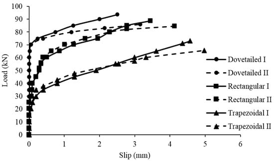
Figure 12.
Load versus slip curve of profiled composite slabs for trials I and II.
From the early stage of loading, end slips have been found and at initial loading it is zero. Up to a certain load, the end slips to the first crack is very low. After that the end slips rate gradually increases with load until failure. Slips of the trapezoidal profiled slabs are greater compared to that of other profiled slabs. Furthermore, resistance to vertical separation is achieved with dovetailed, or re-entrant, profiled slabs whereas vertical separations were visible in trapezoidal profiled slabs. Along with the slips, delamination also took place. With an increase in load, the vertical separation of the steel sheet and the concrete takes place.
5.4. Modes of Failure
Flexure, shear on support and shear bond mode are the three main modes of composite slab failure. Flexure mode of failure is purely due to bending action of slabs where the resisting moment is less. Trapezoidal slabs and rectangular slabs failed by flexure, whereas dovetailed, or re-entrant, slabs showed high resisting moment when compared with the other two types of slabs.
The failure mode of the shear bond is defined by the formation of a diagonal tension crack at or near the supports in the concrete. The chemical bond, resulting from the chemical adhesion of the cement paste to the steel sheeting, is broken in the second stage and the slips are initiated. A popping sound indicates the loss of chemical bond. Due to the interlocking between the profiled steel sheeting and the concrete by means of friction between the steel deck and the concrete, the frictional bond is in the final stage. The shear connectors fail, leading to concrete and steel sheet vertical separation. Figure 13 indicates the vertical separation observed in trapezoidal profiled composite slabs.
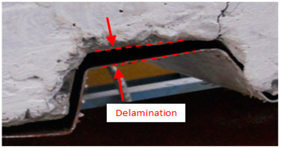
Figure 13.
Debonding failure of trapezoidal profiled composite slab.
5.5. Strain Energy
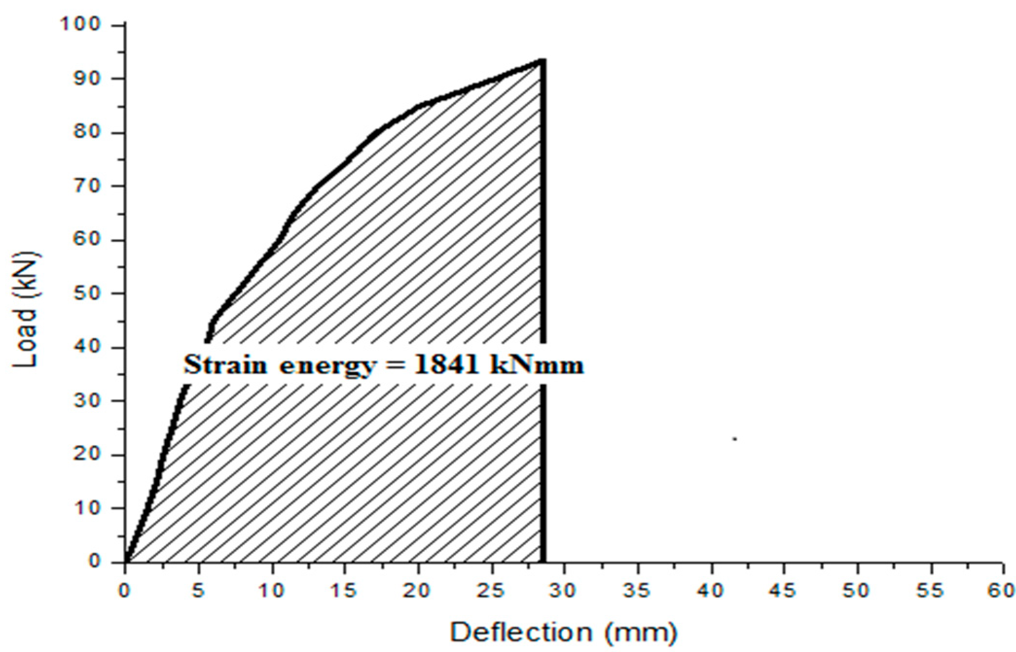
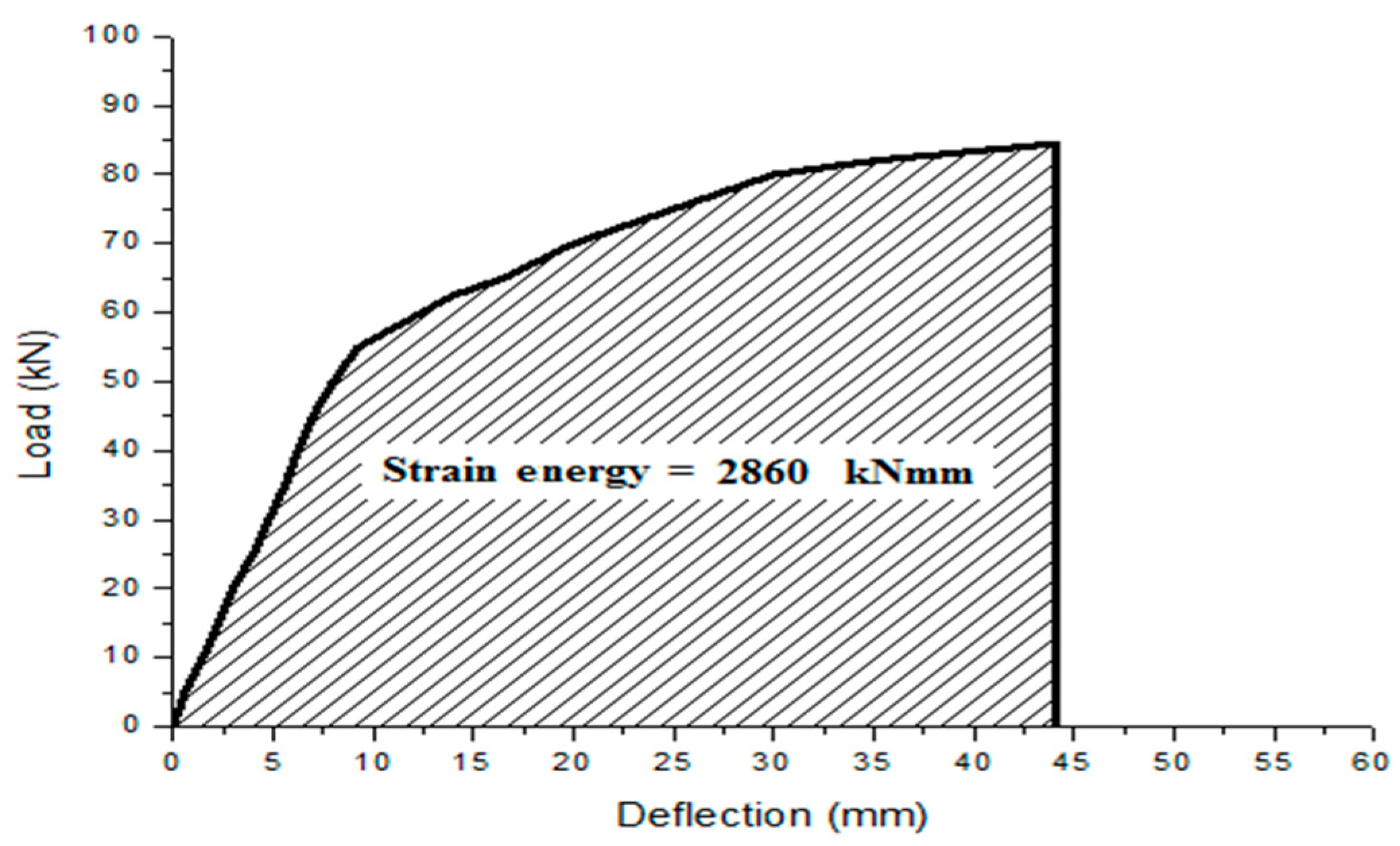
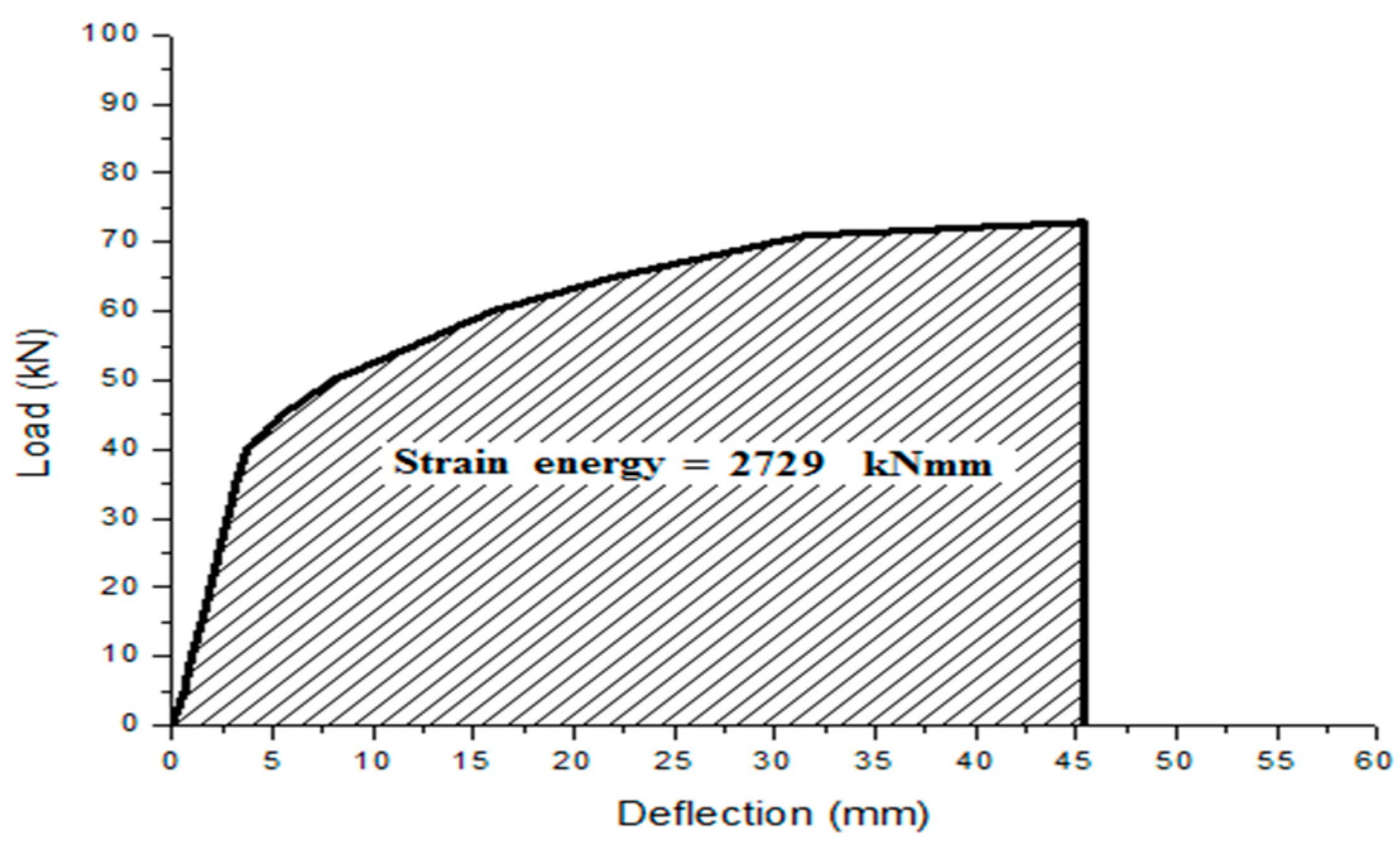
The total energy stored by the composite deck slabs under static flexural load was determined from the load defection behavior. The area plotted between the load and deflection is the total strain energy stored by the material. The strain energy has been calculated for all the three shapes of profiling in the composite slabs. The result shows that the rectangular profiled composite slabs have attained the strain energy of 2.86 kNm and the dovetailed profiled composite slabs are 2.1 kNm. The trapezoidal profiled composite slabs attained the maximum strain energy of 2.98 kNm. However, the trapezoidal profiled slabs have 22.03% lower load carrying capacity compared to dovetailed profiled composite slabs. The higher value of deflection in the trapezoidal profiled composite slabs is responsible for the higher strain energy carrying capacity of the sections. Energy stored in the composite slabs is shown in the Figure 14, Figure 15 and Figure 16.
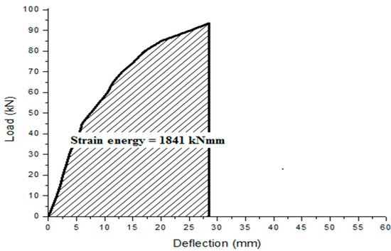
Figure 14.
Strain energy for dovetailed profiled composite slab—Trial I.
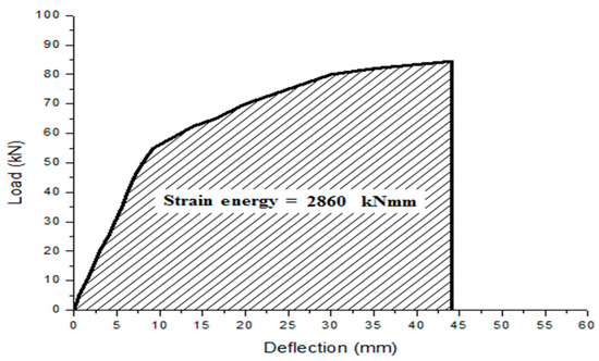
Figure 15.
Strain energy for rectangular profiled composite slab—Trial I.
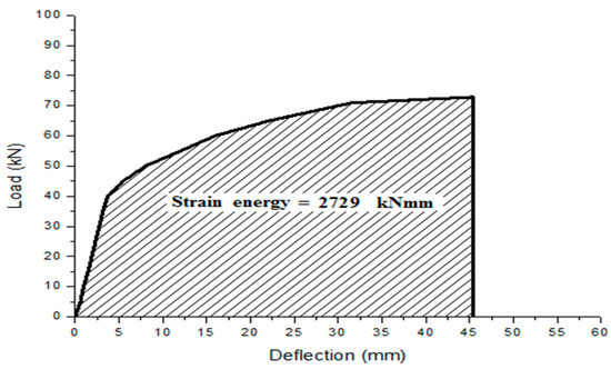
Figure 16.
Strain energy for trapezoidal profiled composite slab—Trial I.
5.6. Ductility Ratio
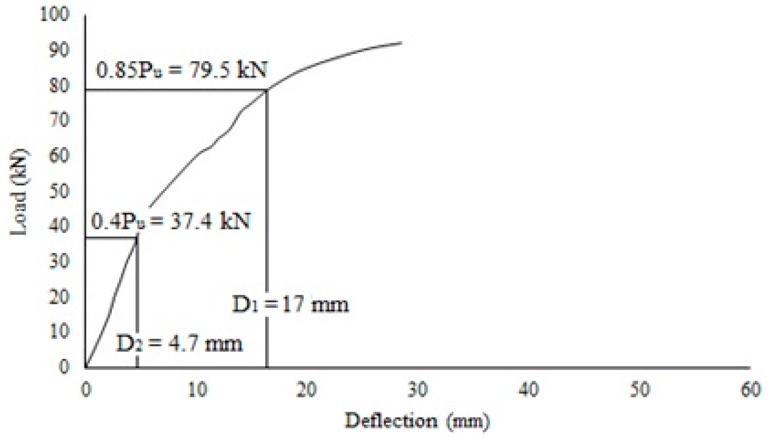
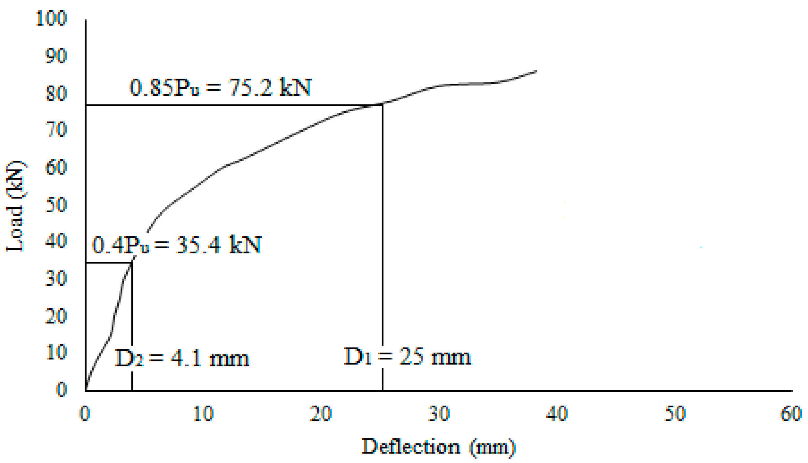
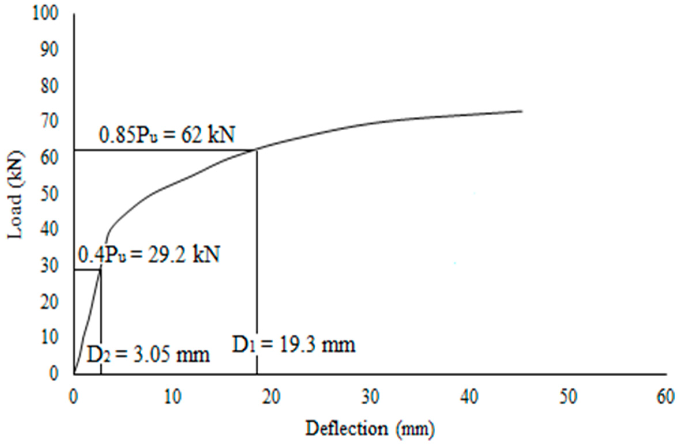
According to Zaho, X.L [22], the ductility ratio is known as the displacement ratio that corresponds to 85% of the final load in the post-ultimate region to the displacement in the yield region. The ratio is estimated from the composite slab’s load-deflection behavior at the elastic limit. The ductility ratio is defined as the ratio of the curvature at ultimate moment to the curvature at yield for the specimen failing in flexure. It can be characterized by the deformation capacity of specimens after yielding or ability to dissipate energy. The author recommended P > 0.4 P0 for the earthquake regions. Siva, A. et al. [23,24,25,26] investigated the longitudinal behavior of composites with trapezoidal profile sheet. The deflection at the elastic limit is the deflection at which the behavior changes from elastic to plastic. In this case, from Figure 17, Figure 18 and Figure 19 the ductility ratio of tested slabs was deduced from the load-deflection graphs. Trapezoidal slabs exhibit maximum deflection for the lowest increase in load, while dovetailed slabs showed the lowest deflection.
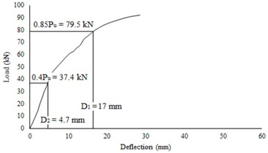
Figure 17.
Ductility ratio for dovetailed profiled composite slab.
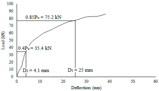
Figure 18.
Ductility ratio for rectangular profiled composite slab.
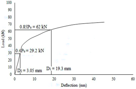
Figure 19.
Ductility ratio for trapezoidal profiled composite slab.
Ductility index is one method available in literature to quantify section ductility [27]. Several researchers have used the ductility index based on load versus axial deformation or load versus axial strain curves [28,29]. We note that the same definition has been adopted in [30,31,32].
From the test results of three different profiles, the dovetailed profiled composite slabs attained the lowest ductility ratio of 2.85. The trapezoidal profile is greater than the rectangular profile by 36.3% and the dovetailed profile by 55%. The ductility ratio and the strain energy stored by the different specimen profile types are shown in Table 5.
Table 5.
Strain energy and ductility ratio for three types of profiled slabs.
6. Conclusions
From various experimental investigations, the behavior of the composite deck slabs with different profiled sheeting is discussed. The best cold-formed sheeting profile that suits the composite slabs is chosen. The following findings are taken from the experimental test results performed on specimens with various profiles.
- The behavior of the shear connector composite deck slabs largely depends on the ratio of opening width at the rib to opening width at the top flange (br/bf).
- The dovetailed composite deck slabs’ load carrying capacities are 5.35% and 22.03% greater than rectangular and trapezoidal profiled composite slabs, respectively.
- Deflection and slips of dovetailed, or re-entrant, profiled slabs are lower compared to rectangular and trapezoidal profiled slabs.
- Dovetailed, or re-entrant, profiled slabs showed high resistance to vertical separation.
- The trapezoidal profiled composite slabs attained the maximum strain energy of 2.98 kNm.
- The strain energy stored by the material is lower for the dovetailed profiled composite slabs when compared to rectangular and trapezoidal profiled composite slabs.
- Increasing the ratio of opening width of ribs to flange width increases the ductility ratio.
- The ductility ratio for trapezoidal profile is 36.3% and 55% higher when compared to rectangular and dovetailed profiled composite slabs, respectively.
- Trapezoidal profiled slabs failed by shear bond mode which is the predominant failure in composite slabs which should be minimized.
- The slip at early stages was negligible for all the specimens. In the plastic stage, the magnitude of slip increased significantly with loading.
- The elastic and plastic behavior of the specimen mainly depends on shear span and loading. Short shear span is recommended, if the investigation is focused of the elastic behavior and long shear span for plastic behavior.
- For all the composite deck slabs failing in flexure, the ductility ratio can be defined as the ratio of curvature at ultimate to yield moment capacity.
- Ductility characterizes, after yielding, of the deformation capacity of trapezoidal composite deck slabs was higher than its energy dissipation ability when compared to other composite deck slabs.
Further Studies:
- The embossments shown in flange will insightful increase the shear resistance of the composite deck systems.
- The different types, depth and orientations of embossments can be further investigated.
- The bond strength of the composite deck systems can be investigated with chemical adhesives.
- Numerical and analytical investigation for such composite systems with embossments and chemical adhesives are insufficient. Such investigations can possibly develop a new empirical formula for composite deck systems.
Author Contributions
Conceptualization, S.A., E.I.S.F. the G.A.-L.; methodology, S.A., E.I.S.F., G.A.-L. and W.J.T.; validation, S.A., E.I.S.F. and S.N.R.; resources, S.A., E.I.S.F. and G.A.-L.; data curation, S.A., E.I.S.F. and G.A.-L.; writing—original draft preparation, S.A., E.I.S.F. and G.A.-L.; writing—review and editing, M.A., R.F., G.M., N.V. and M.K.; supervision, S.A. and E.I.S.F.; project administration, S.A. and E.I.S.F.; funding acquisition, M.K. and N.V. All authors have read and agreed to the published version of the manuscript.
Funding
The research is partially funded by the Ministry of Science and Higher Education of the Russian Federation as part of World-class Research Center program: Advanced Digital Technologies (contract No. 075-15-2020-934 dated 17 November 2020).
Institutional Review Board Statement
Not applicable.
Informed Consent Statement
Not applicable.
Data Availability Statement
Data can be shared upon direct request.
Acknowledgments
S. Avudaiappan and E.I. Saavedra Flores acknowledge funding coming from Universidad de Santiago de Chile, Usach, Proyecto POSTDOC_DICYT, Código 052018SF_POSTDOC, Vicerrectoría de Investigación, Desarrollo e Innovación.
Conflicts of Interest
The authors declare no conflict of interest.
References
- Burnet, M.J.; Oehlers, D.J. Rib shear connectors in composite profiled slabs. J. Constr. Steel Res. 2001, 57, 1267–1287. [Google Scholar] [CrossRef]
- Akhand, A.M.; Wan Badaruzzaman, W.H.; Wright, H.D. Combined flexure and web crippling strength of a low-ductility high strength steel decking: Experiment and a finite element model. Thin-Walled Struct. 2004, 42, 1067–1082. [Google Scholar] [CrossRef]
- Kim, H.; Jeong, Y. Ultimate strength of a steel concrete composite bridge deck slab with profiled sheeting. Eng. Struct. 2010, 32, 534–546. [Google Scholar] [CrossRef]
- Wright, H.D.; Evans, H.R.; Harding, P.W. The Use of Profiled Steel Sheeting in Floor Construction. J. Constr. Steel Res. 1987, 7, 279–295. [Google Scholar] [CrossRef]
- Baskar, R.; Antony Jeyasehar, C. Experimental and Numerical Studies on Composite Deck Slabs. Int. Eng. Res. Dev. 2012, 3, 22–32. [Google Scholar]
- Mohammed, B.S.; Al-Ganad, M.A.; Abdullahi, M. Analytical and experimental studies on composite slabs utilising palm oil clinker concrete. Constr. Build. Mater. 2011, 25, 3550–3560. [Google Scholar] [CrossRef]
- Prajapati, K.K.; Vanza, M.G.; Vakil, M.D. Behavior of Cold-formed Stainless Steel Composite Deck. Int. J. Earth Sci. Eng. 2011, 4, 616–618. [Google Scholar]
- Chen, S.; Shi, X. Shear bond mechanism of composite slabs—A universal FE approach. J. Constr. Steel Res. 2011, 67, 1475–1484. [Google Scholar] [CrossRef]
- Abdullah, R.; Samuel, W.E. New evaluation and modeling procedure for horizontal shear bond in composite slabs. J. Constr. Steel Res. 2009, 65, 891–899. [Google Scholar]
- Chen, S. Load carrying capacity of composite slabs with various end constraints. J. Constr. Steel Res. 2003, 59, 385–403. [Google Scholar] [CrossRef]
- Eldib, M.E.; Maaly, H.M.; Beshay, A.W.; Tolba, M.T. Modelling and analysis of two-way composite slabs. J. Constr. Steel Res. 2009, 65, 1236–1248. [Google Scholar] [CrossRef]
- Hedaoo, N.A.; Gupta, L.M.; Ronghe, G.N. Design of composite slabs with profiled steel decking: A comparison between experimental and analytical studies. Int. J. Adv. Struct. Eng. 2012, 4, 1. [Google Scholar]
- Marimuthu, V.; Seetharaman, S.; Arul Jayachandran, S.; Chellappan, A.; Bandyopadhyay, T.K.; Dutta, D. Experimental studies on composite deck slabs to determine the shear-bond characteristic (m–k) values of the embossed profiled sheet. J. Constr. Steel Res. 2007, 63, 791–803. [Google Scholar] [CrossRef]
- Design of Composite Steel and Concrete Structures—General Rules and Rules for Buildings; EN 1994: Part 1; European Committee for Standardization, 2003; Available online: http://www.phd.eng.br/wp-content/uploads/2015/12/en.1992.1.1.2004.pdf (accessed on 9 September 2020).
- Structural Use of Steelwork in Building—Code of Practice for Design of Composite slabs with Profiled Steel Sheeting; BS 5950: Part 4; British Standards Institution (BSI): London, UK, 1994; Available online: https://www.ihsti.com/CIS/document/83107 (accessed on 9 September 2020).
- Baskar, R. Experimental and numerical studies on composite deck slabs. Int. J. Eng. Technol. 2012, 2, 1116–1125. [Google Scholar]
- Lakshmikandhan, K.N.; Sivakumar, P.; Ravichandran, R.; Arul Jayachandran, S. Investigations on efficiently steel concrete composite deck slab. J. Struct. 2013, 10, 628759. [Google Scholar]
- Indian Standard Committee. Specifications for Coarse and Fine Aggregates from Natural Sources for Concrete; IS 383; Bureau of Indian Standards: New Delhi, India, 1970. [Google Scholar]
- Indian Standard Committee. Indian Standard Code of Methods of Sampling and Analysis of Concrete; IS 1199; Bureau of Indian Standards: New Delhi, India, 1959. [Google Scholar]
- Indian Standard Committee. Indian Standard Code of Plain and Reinforced Concrete Code of Practice; IS 456; Bureau of Indian Standards: New Delhi, India, 2000. [Google Scholar]
- Indian Standard Committee. Indian Standard Code of Recommended Guidelines for Concrete Mix Design; IS 10262; Bureau of Indian Standards: New Delhi, India, 2009. [Google Scholar]
- Han, L.H.; Zhao, X.L.; Tao, Z. Tests and Mechanics Model for Concrete-filled SHS Stub Columns, Columns and Beam-Columns. Steel Compos. Struct. 2001, 1, 51–74. [Google Scholar]
- Siva, A.; Senthil, R.; Saddam, M.A. Experimental investigation on longitudinal shear behaviour of steel concrete composite deck slab. J. Struct. Eng. 2016, 43, 445–453. [Google Scholar]
- Siva, A.; Swaminathan, S.; Prasanth, K.; Senthi, R. Experimental Investigation of Trapezoidal Profile Sheeting Under Varying Shear Spans. Appl. Mech. Mater. 2016, 845, 148–153. [Google Scholar] [CrossRef]
- Sheet, I.S.; Ahmed, S.M.; Avudaiappan, S.; Flores, E.I.S.; Chandra, Y.; Astroz, R. Shear bond behaviour of elemental composite beams with different configurations. Eng. Struct. 2019, 201, 109742. [Google Scholar] [CrossRef]
- Ahmed, S.M.; Avudaiappan, S.; Sheet, I.S.; Flores, E.I.S.; Pina, J.C.; Yanez, S.J.; Guzmán, C.F. Prediction of longitudinal shear resistance of steel-concrete composite slabs. Eng. Struct. 2019, 193, 295–300. [Google Scholar]
- Murray, N.W. Introduction to the Theory of Thin-Walled Structures; Clarendon Press: Oxford, UK, 1986. [Google Scholar]
- Zhao, X.L.; Hancock, G.J. Tests to determine plate slenderness limits for cold-formed rectangular hollow sections of grade C450. Steel Construction. Aust. Inst. Steel Constr. 1991, 25, 2–16. [Google Scholar]
- Ge, H.B.; Usami, T. Cyclic tests of concrete filled steel box columns. J. Struct. Eng. ASCE 1996, 122, 1169–1177. [Google Scholar]
- Tao, Z.; Han, L.H.; Zhao, X.L. Behaviour of square concrete filled steel tubes subjected to axial compression. In Proceedings of the Fifth International Conference on Structural Engineering for Young Experts, Shenyang, China, 1998; pp. 61–67. [Google Scholar]
- Siva, A.; Senthil, R.; Swaminathan, S. Assessment of longitudinal shear strength of composite deck slab. Int. J. Innov. Sci. Res. 2016, 24, 277–284. [Google Scholar]
- Siva, A.; Thamilselvi, P.; Saddam, M.A.; Senthil, R. Concrete composite slab construction: State of the art. Int. J. Res. Eng. Technol. 2017, 6, 120–128. [Google Scholar]


Publisher’s Note: MDPI stays neutral with regard to jurisdictional claims in published maps and institutional affiliations. |
© 2021 by the authors. Licensee MDPI, Basel, Switzerland. This article is an open access article distributed under the terms and conditions of the Creative Commons Attribution (CC BY) license (http://creativecommons.org/licenses/by/4.0/).