Abstract
The load increase method, which is highly efficient in rapidly identifying the fatigue performance and strength of materials, is used in this study to investigate friction stir welded (FSW) EN AW-5754 aluminum alloys. Previous investigations have demonstrated the accuracy and efficiency of this method compared to Woehler tests. In this study, it is shown that the load increase method is a valid, accurate and efficient method for describing the fatigue behavior of FSW weld seams. The specimen tests were performed on 2 mm thick aluminum sheets using conventional and stationary tool configurations. It is shown that an increase in fatigue strength of the FSW EN AW-5754 aluminum alloys can be achieved by using the stationary shoulder tool configuration rather than the conventional one.
1. Introduction
Friction stir welding (FSW), which was patented by the Welding Institute (UK) in 1991, has emerged as a promising solid-state joining technique. Researchers have successfully applied FSW in the joining of various similar and dissimilar materials in numerous industrial applications [1,2,3,4]. It has been noted that FSW ensures the production of joints with excellent mechanical properties that can be used for various metallic and nonmetallic materials. Compared to conventional welding methods, the unique advantage of FSW is the absence of process gases and filler materials as well as the joining of materials with restricted weldability. Furthermore, the joining temperatures are below the liquidus temperature, which prevents weld seam irregularities such as pores and hot cracks [5,6].
The FSW process based on a rotating tool consists of a shoulder and probe. The tool plunges into the workpiece through axial pressure, and the material is plasticized by frictional heat. The tool subsequently moves along the designated welding path (Figure 1). A complex material flow is formed by the shoulder and probe during the continuous plasticizing; the material is displaced behind the tool and forms the weld seam.
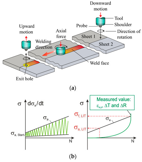
Figure 1.
(a) Operating principle of friction-stir welding (FSW); (b) characteristics of the continuous load increase test (LIT).
The application of FSW can be performed by varying tool configurations such as conventional and stationary shoulder. In the conventional tool design, the shoulder and the probe are connected to each other and rotate with the same rotational speed and direction. Although this setup is comparatively simple and easy to handle, challenges include comparatively high surface roughness and asymmetrical material flow and temperature distribution in the joining area. However, the unfavorable microstructure and surface properties of FSW weld seams performed with conventional tool configurations can negatively affect fatigue properties due to increased surface roughness.
In the stationary shoulder configuration, the probe is the only rotating part in the FSW tool and it generates the main heat input. The use of the stationary shoulder configuration reduces the process forces so that an improvement of the final surface quality can be achieved. This property results from the fixed shoulder that glides across the weld seam surface and ensures a reduction of the roughness [7]. The challenges of the stationary shoulder configuration can be explained by a complex process handling due to the material flow between shoulder and probe. Previous investigations have shown an increased wear behavior on the probe and the necessity of separating excess material from the joining area [7]. It was consequently noted that the conventional and stationary shoulder configuration exhibits an advantage with regard to process handling and achievable weld seam properties.
An increasing demand for low fuel-consumption vehicles provides a motivation for manufacturers to provide more efficient parts. The new parts have to weigh less and at the same time possess strong mechanical properties and increased functionality. The EN AW-5754 (AlMg3) aluminum alloy is selected in this study because it is frequently used in light-weight industries such as automobile and aerospace.
The load increase test (LIT) is a rapid fatigue performance identification method that has been used for characterizing various material categories from metals to polymers and has the potential to reduce the time and cost of experiments by up to 90% compared to the constant amplitude test (CAT) [8,9]. It has been shown that this procedure is able to accurately predict the fatigue limit of materials in constant amplitude tests [8,9,10].
There is currently a very limited number of studies available on the fatigue behavior of FSW EN AW-5754 aluminum alloys. The existing literature mainly investigated the fatigue properties of aluminum alloys using CAT and not LIT [11]. The present study aims to investigate the effect of different tool configurations (conventional and stationary shoulder) on the fatigue behavior of FSW EN AW-5754 aluminum alloy by LIT and CAT. A second aim of this study is to investigate the reliability and reproducibility of the LIT method for characterization of fatigue behavior of EN AW-5754 FSW specimens.
2. Experimental Procedure
To investigate the effect of different FSW configurations on the fatigue properties of EN AW- 5754, sheets with 2 mm thickness, 600 mm length and 170 mm width were used for the evaluation of the accuracy of the LIT method. The chemical composition of the Al alloy used in this study is shown in Table 1.

Table 1.
Composition of EN AW-5754 H22 [EN 573-3:2013].
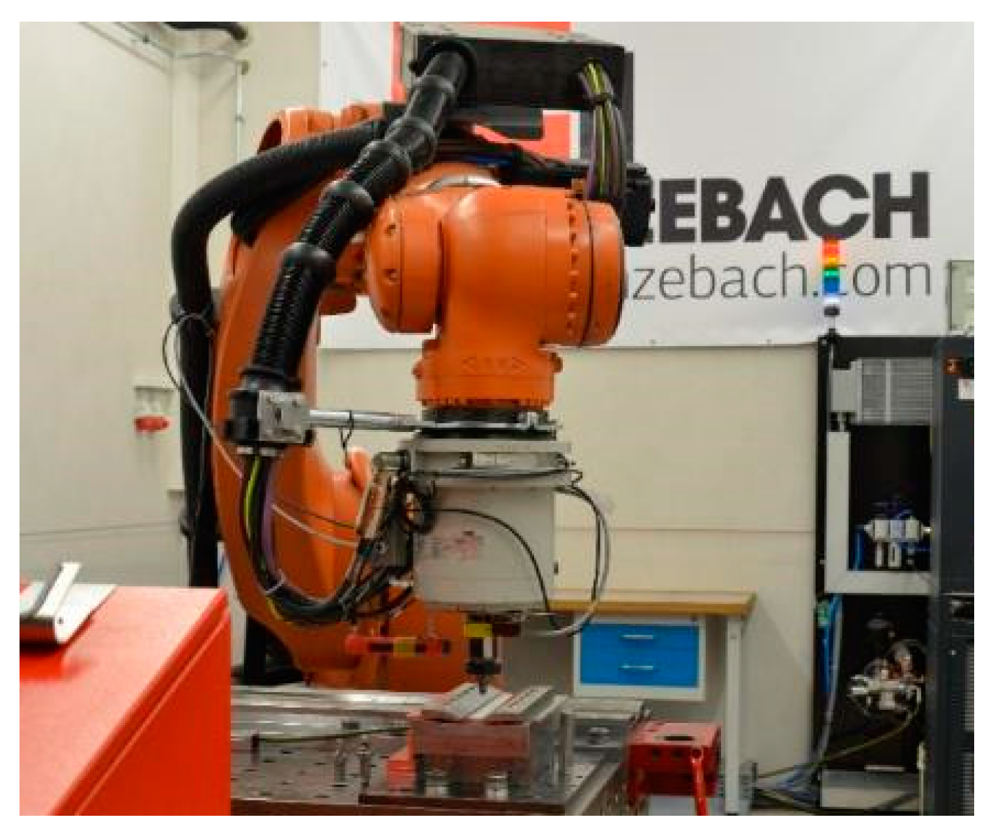
The welding experiments were performed with a robotized, force-controlled FSW setup (modified Kuka KR500 heavy-duty robot from Grenzebach Maschinenbau GmbH, 86663 Asbach-Bäumenheim, Germany) that provides an axial force up to 10 kN and a maximum rotational velocity of 14,000 rpm (Figure 2).
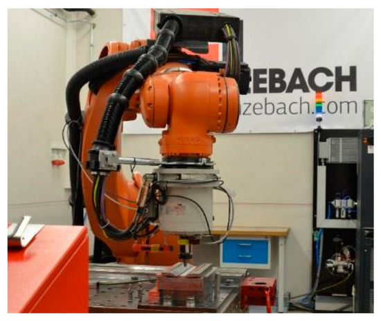
Figure 2.
Robotized FSW setup and clamping structure.
The geometry of each toolset is shown in Figure 3. The conventional tool was manufactured in-house from hot-working steel 1.2344 (X40CrMoV5-1). The 8 mm shoulder in the conventional tool has a 10° concavity to keep the plasticized material below the shoulder. This prevents the occurrence of irregularities such as flash formation. To increase the material flow in the joining area, the probe was designed with a tapered geometry, a thread and three flanks. The aspect ratio between the shoulder and probe in the conventional configuration was 2.6.
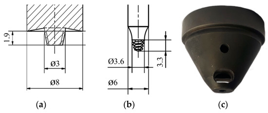
Figure 3.
(a) Conventional FSW tool, (b) probe and (c) shoulder of stationary shoulder tool setup with dimesions in mm.
The stationary shoulder tool was purchased from Grenzebach Maschinenbau GmbH. To ensure comparability, the stationary shoulder has a diameter of 8 mm. However, it was designed with no concavity. The probe in the stationary shoulder setup also had a tapered geometry and a thread.
The rotational speeds for conventional and stationary shoulder FSW were 3000 and 11,500 rpm and the process forces 3750 and 3400 N, respectively. During the welding process for both designs, the penetration depth was 95% (i.e., 1.9 mm) of the sheet thickness. The experiments were performed in butt joint configuration, with a welding speed of 1000 mm/min and a constant tilt angle of 2°.
The specimens were cut from the welded sheets by a milling process in accordance with DIN 50125. The specimen geometry is shown in Figure 4a. The welding process reached a relatively steady-state mode in the middle of the Al sheets, and hence the specimens were extracted from this section (Figure 4b). The first 50 mm from each side of the sheets was discarded because of the fluctuations during the welding process. To ensure a high weld seam quality and a complete through-weld, bending tests were performed from the root side. These tests detect weld seam irregularities in the inner and on the root side that can favor the initiation of cracks. The specimen edges were polished after the extraction to minimize the effects of the milling on the edges of the specimens.
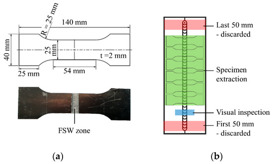
Figure 4.
(a) Specimen geometry and (b) extraction position of the milled specimens.
The quasi-static properties of the FSW EN AW-5754 sheets were investigated by tensile tests using a Shimadzu universal testing system (AG-100kNX, Shimadzu, Kyoto, Japan) with a load cell of 100 kN in accordance with ISO 6892-1:2016. During the tensile tests, the total strain (εt) of the specimens was monitored using an extensometer (Shimadzu, Kyoto, Japan) with a gauge length of 50 mm and a strain measurement range of ±5 mm (10%) at an initial strain rate of 𝜀̇ = 2.5 × 10⁻⁴ s−1. As the strain reached the maximum allowable measurement range of the extensometer, it was removed from the setup and the tensile test was continued with a strain rate of 𝜀̇ = 6.7 × 10⁻³ s−1 controlled by the stroke. Tensile tests for each welding procedure were repeated twice.
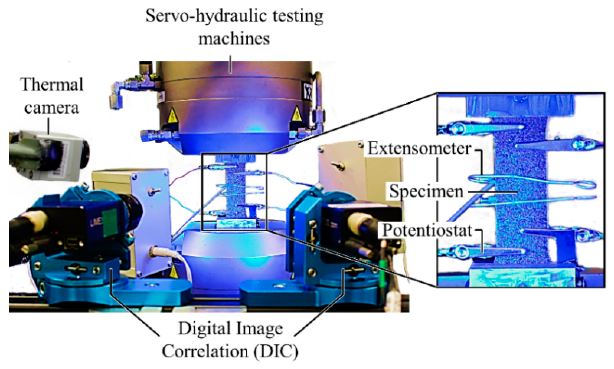
An Instron servohydraulic testing system (8801, Instron, High Wycombe, United Kingdom) with a load cell of 100 kN (Figure 5) was used to investigate the fatigue properties of the FSW Al alloy specimens. The fatigue investigations were initiated with LIT. It started at a maximum stress level of σmax,start = 20 MPa on the basis that this pressure is far below the fatigue limit and material would therefore be free of damage. The stress level was subsequently increased continuously from a rate of dσmax/dt = 10 MPa/104 until the specimen fractured. The testing frequency was 10 Hz, and the stress ratio was pure tension (R = 0.1). For each configuration, three LITs were carried out to ensure the reliability of the results. During the tests, an extensometer (Instron, High Wycombe, United Kingdom) with a gauge length of 12.5 mm and a strain measurement range of ±40% was used for strain measurement.

Figure 5.
Experimental setup for fatigue tests.
To gain deeper knowledge regarding the local deformations of the specimens, the optical measurement technique of 3D-digital image correlation (DIC) by Limess was used. This system uses a full-field image analysis technique to generate strain maps over the entire specimen during a fatigue test. This system was synchronized with the testing frequency of the testing system (10 Hz) using a frequency-dependent triggered image acquisition technique. In addition to the extensometer and DIC, an electrical measuring system (Gamry Interface 1000 A potentiostat) was used to obtain complementary results with respect to damage detection. The principle of this system is the injection of alternating current (AC) into the specimen to create a current flow between the working electrodes and detection of the changes in the voltage by the counter electrodes. The changes in voltage are triggered by the occurrence and evolution of damage (i.e., crack initiation and growth). A µε TIM 160 thermal imaging camera with a measurement range of −20 to 900 °C and thermal sensitivity of 80 mK was also used. The change in temperature ΔT = T1 − 0.5 × (T2 + T3) was calculated after the test based on the temperatures at the center of the weld nugget (T1) and at points 20 mm higher and lower than the weld nugget (T2, T3).
To cover the regime of this specimen relevant to potential applications (high cycle fatigue), four stress amplitudes were chosen for the CAT based on the results obtained from LIT. Three tests were performed for each amplitude using LIT setup.
In this study, the influence of the conventional and stationary shoulder FSW on the mechanical properties of the specimens was investigated. After the tests, the fracture surfaces of the specimens were analyzed using light microscopy to determine the fracture mechanisms.
3. Results and Discussion
3.1. Quasi-Static Properties
The results for the quasi-static tensile tests are shown in Figure 6. As can be seen, the stationary shoulder weld shows higher quasi-static strength than the conventional FSW. The yield strength and the ultimate tensile strength of the stationary shoulder sample reach 152.1 and 234.7 MPa, which are 9% and 11% higher than the conventional FSW samples (139.6 and 212.3 MPa). The stationary shoulder weld exhibits a higher ductility, with its corresponding total strain being improved 5% more than the conventional sample. However, the specimens manufactured with both configurations show lower strength and ductility than the base material with yield strength, ultimate tensile strength and total strain of 178.7 MPa, 245.6 MPa and 14.5, respectively.

Figure 6.
Quasi-static tensile test results of the base material, conventional and stationary shoulder FSW specimens.
All of the tensile curves show a serration in the plastic region, which is due to the Portevin-Le Chatelier (PLC) effect, a common phenomenon in the magnesium-based Al alloys such as EN AW-5754 [12].
3.2. Fatigue Properties
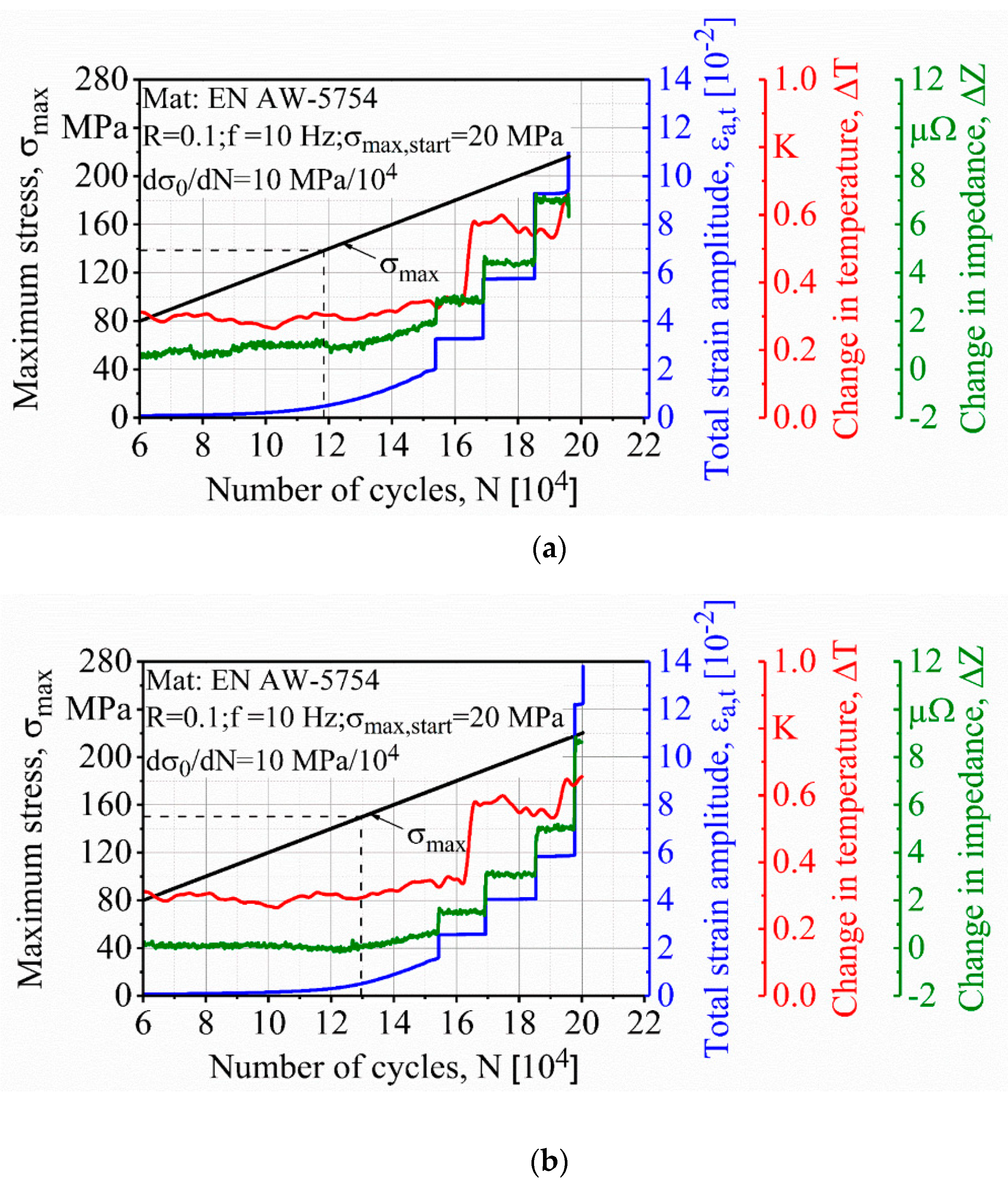
Figure 7a,b show the results of the LIT for conventional and stationary shoulder FSW respectively. The material response was monitored by extensometer, digital image correlation (DIC), thermal camera and potentiostat. As can be seen, all measurement techniques detect a stepwise material response arising from the cyclic creep phenomenon associated with the PLC effect. This effect is also known as dynamic strain aging and has been fully explained in the literature [13]. The thermal measurements do not detect any major increase in the temperature change due to the plasticization of the specimens, which again suggests the existence of the cyclic creep phenomenon.
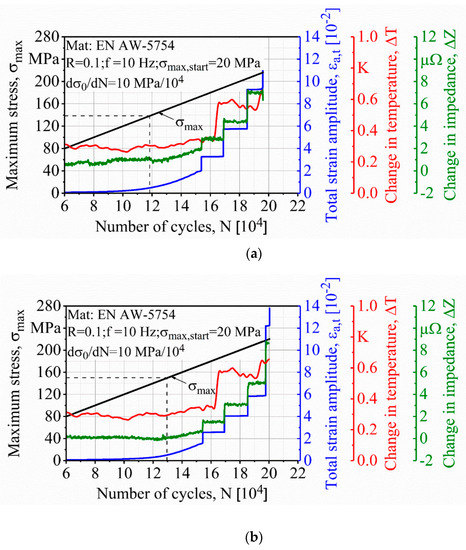
Figure 7.
Load increase test results for specimens made by (a) conventional and (b) stationary shoulder FSW.
LIT results show three distinct regions in material response. The material initially shows a constant response when the stress level is in the damage-free zone. Afterwards, there is a linear change in the LIT slope that indicates the first material response. Finally, the LIT slope exponentially increases as a function of internal damage within the material and eventually the specimen fractures. Studies have shown that the starting point of the second region corresponds very well with the fatigue limit of the material and can be considered as an early prediction of fatigue strength [8,9,10,14].
It can be seen from the strain measurements that the stationary shoulder FSW shows slightly better fatigue properties in LIT. The stationary shoulder specimen shows the first signs of linear material behavior change at 151 MPa, and it fractured at a maximum stress of 220 MPa after 2.0 × 10⁵ cycles. However, for the conventional specimen, the first material response is detected at 139 MPa and it fails at a maximum stress of 216 MPa after 1.9 × 10⁵ cycles.
The potentiostat is able to detect early stage damage of the conventional specimen in response to a load increasing to around 80 MPa where the extensometer and DIC do not detect any significant change in the material response. However, the electrical measuring system does not show any early stage damage within the stationary shoulder specimen and its result is mostly comparable to the rest of the measurement techniques.
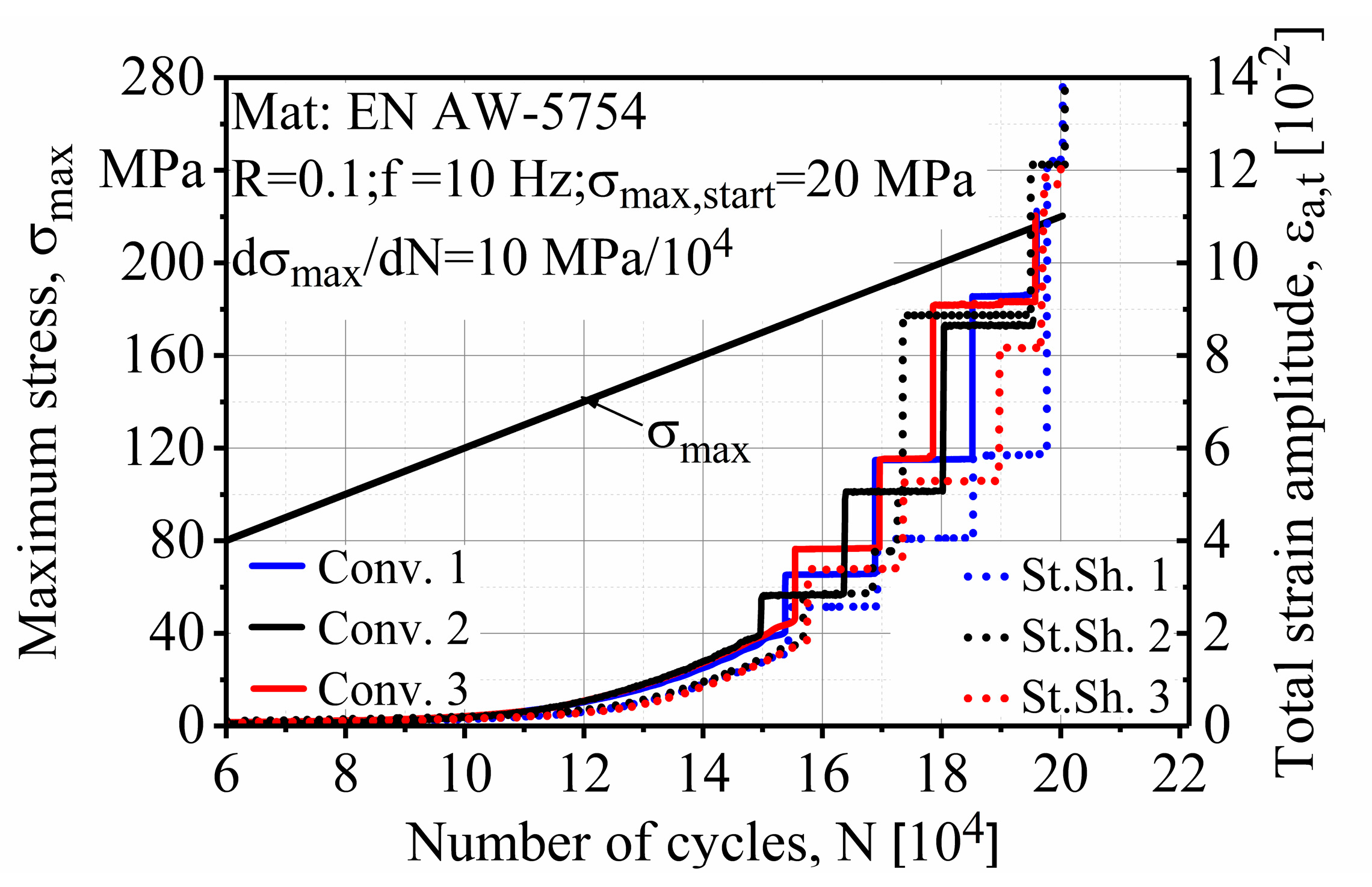
As it is shown in Figure 8, all the conventional (Conv.) and stationary shoulder (St. Sh.) results are very similar to each other. The estimated fatigue strengths in LIT results of the conventional and stationary shoulder are in the range 138 ± 1 MPa and 150 ± 1 MPa and show only 0.7% and 0.6% standard deviation, respectively. The same similarity can be detected in the fracture stress, which is in the range 216.0 ± 0.5 and 220.7 ± 0.9 MPa for the conventional and stationary shoulder with standard deviations of only 0.2% and 0.4%, respectively. These results show the reliability and repeatability of the LIT procedure.

Figure 8.
Comparison of all of the load increase test (LIT) on conventional and stationary shoulder FSW specimens.
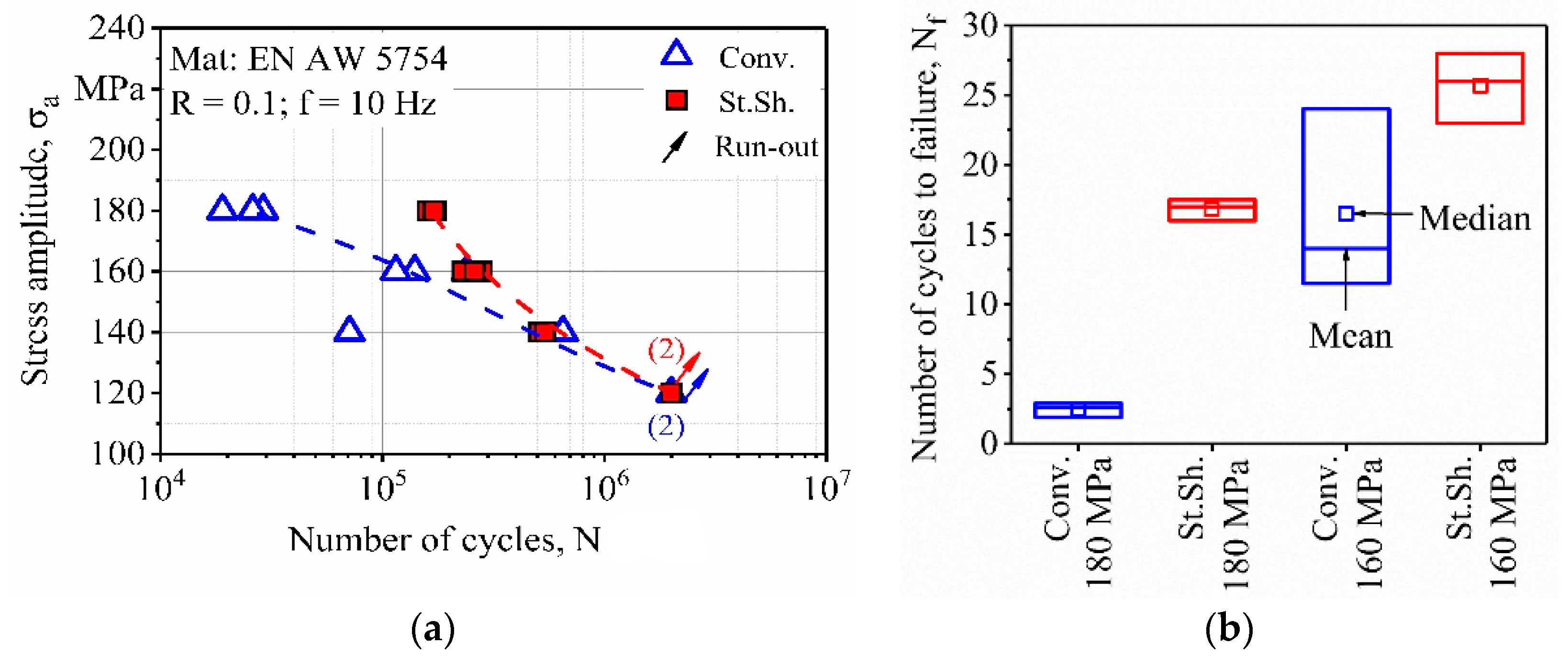
The results obtained from LIT helped to determine a starting stress value for the following CAT. The CAT started with a stress level of 120 MPa for both FSW specimens where a uniform material behavior is expected up to the 180 MPa to cover the high cycle fatigue (HCF) regime. The improved fatigue properties of the stationary shoulder FSW, clearly visible in Figure 9a, is due to its smooth surface and homogenous weld zone microstructure. The results of the specimens manufactured with both tool configurations run-out at 120 MPa. However, the stationary shoulder specimens show superior fatigue properties at higher stress amplitudes. This could be due to the fact that in low cycle fatigue (LCF) regime, microstructure of the specimens has the main influence on their fatigue properties [15]. On the other hand, and in HCF towards the very high cycle fatigue (VHCF) regime, internal defects and residual stresses are the main contributing parameters influencing their change of fatigue properties [15]. This suggests that the main advantage of the stationary shoulder FSW to the conventional FSW is the improvement of the microstructure (i.e., finer microstructure). In addition, it can be seen that stationary shoulder specimens show a relatively lower scatter in fatigue life than the conventional specimens. This can be explained by the comparatively higher roughness properties of the weld seam surface measured on the conventional (Rz = 212 µm, Ra = 23 µm) and stationary shoulder (Rz = 6 µm, Ra = 2 µm) specimens, which acted as multiple crack initiation sites.
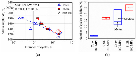
Figure 9.
(a) Woehler curve for fatigue life assessment of friction-stir welding (FSW) specimens and (b) its statistical analysis.
Figure 9b shows the statistical analysis of the CAT results of the conventional and stationary shoulder at stress levels of 160 and 180 MPa. It is quite evident that that CAT shows a higher scatter than the LIT, which decreases at higher stress levels. The standard deviation for the conventional FSW at 160 MPa is 6.6, which decreases to 0.5 at 180 MPa. This decrease in standard deviations is also visible for the conventional manufactured specimens from 2.5 to 0.7, as the stress level is increased from 160 to 180 MPa. Another point to note is that the stationary shoulder FSW has a higher mean fatigue life with lower scatter at 180 MPa than the conventional FSW even at 160 MPa.
3.3. Fracture Behavior
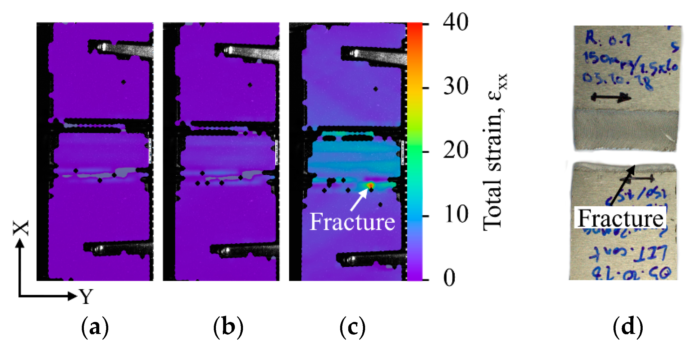
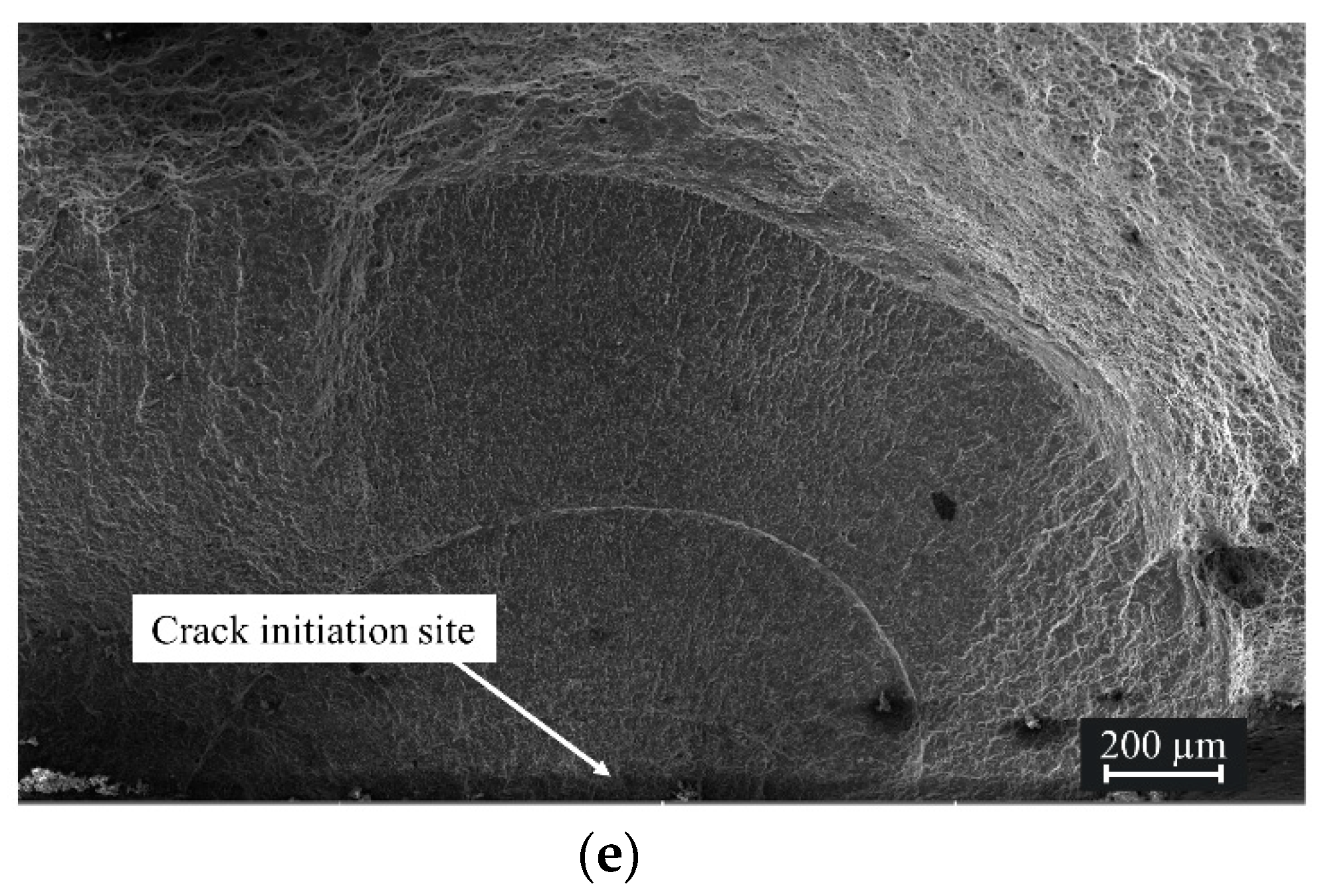
As shown in Figure 10, DIC results show strain concentration in the middle of the specimens at the weld zone. However, it can be seen from the local deformations and the moment of crack initiation that the cracks are initiated from the transition zone between the welding zone and the base material (Figure 10c). This suggests that the weld nuggets possess sufficient durability during the fatigue tests. In most of the fractures, the crack continued to propagate on a straight plane parallel to the weld. In a few cases, a crack from one transition zone propagated across the weld nugget and reached another crack on the other transition zone which caused the fracture. The cracks in the specimens of both FSW setups are initiated from the surface and towards the middle of the specimen in the Y-axis (Figure 10d).
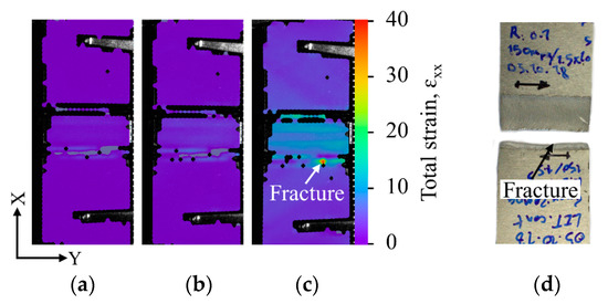

Figure 10.
Digital image correlation (DIC) analysis of a specimen during LIT at (a) 100, (b) 180, (c) 210 MPa and (d) the fractured specimen and (e) SEM image of the crack initiation site.
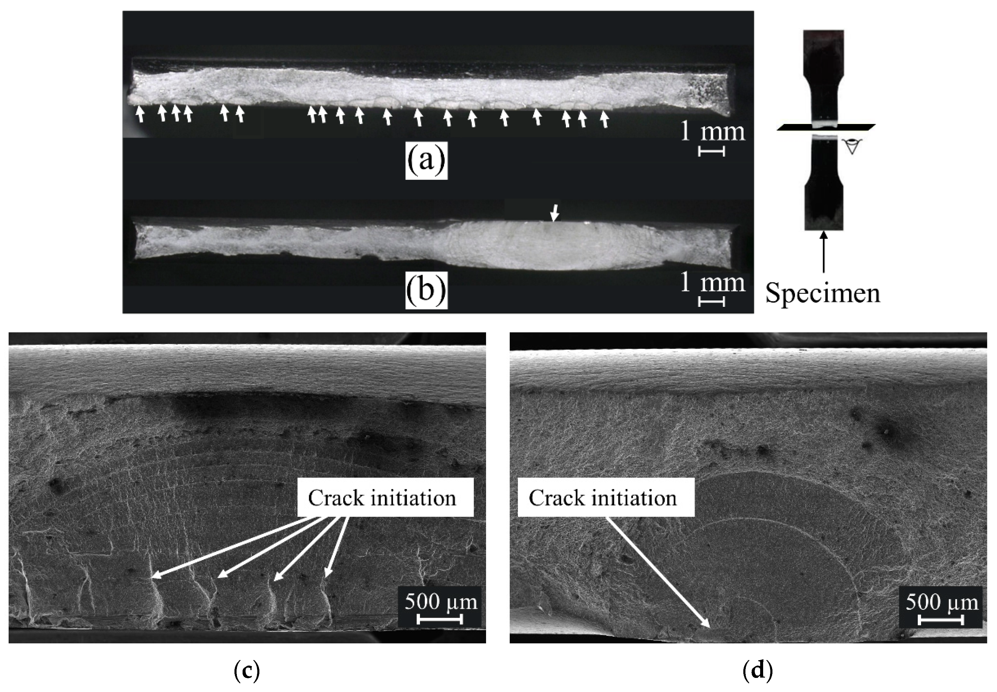
The fracture surfaces of the specimens for each welding procedure were studied to understand the effect of welding procedure on fatigue life. As it is shown in Figure 11, there was one main crack initiation site in the welds made by the stationary shoulder tool while there were multiple crack initiation sites on the fracture surface of the conventional FSW specimen that drastically shortened fatigue life. Although the specimens were characterized by bending test and reveals no visible irregularities, it must be expected that slightest bonding deviations can affect the root side crack initiation. Thus, it can be noted that the manufacturing of the specimens requires a detailed pre-testing procedure of the areas that favor crack initiation.

Figure 11.
Light micrograph of the fracture surface of the (a) conventional and (b) stationary shoulder FSW specimens and SEM image of the crack initiation sites in (c) conventional and (d) stationary shoulder FSW specimens.
The fatigue behavior of relatively new FSW concept of dual-rotational in comparison to the two concepts presented in this study will be investigated in future studies. In addition, this study will be continued with an investigation of the influence of the surface planning and corrosion on the fatigue properties of Al alloys [9].
4. Conclusions
The mechanical properties of the friction stir welded EN AW-5754 sheets using conventional and stationary shoulder FSW were investigated in this study. It was shown that the stationary shoulder FSW samples exhibits higher quasi-static properties (strength and ductility) than the conventional FSW specimens. Fatigue specimens were reliably monitored using electrical resistance measurement, digital image correlation, thermal camera and an extensometer. The fatigue results indicated a stepwise material response for all the specimens which occurred due to the cyclic creep phenomenon associated with the PLC effect. The load increase method and subsequent constant amplitude tests indicated the superior fatigue properties of stationary shoulder FSW specimens (increased estimated fatigue life and fracture stress, reduced scatter and deviation) in comparison with conventional FSW samples. It was shown that the load increase method is an accurate, efficient method with high reproducibility in describing the fatigue behavior of FSW specimens.
Author Contributions
Investigation, A.B.C.; welding process and resources, M.G.; writing—original draft preparation, A.B.C.; writing—review and editing, A.B.C., F.W., M.G. and J.P.B.; supervision, F.W. and J.P.B. All authors have read and agreed to the published version of the manuscript.
Funding
This research was funded by Federal Ministry for Economic Affairs and Energy of Germany (BMWI) within the IGF project 19566 BG.
Acknowledgments
The financial funding of the Federal Ministry for Economic Affairs and Energy of Germany (BMWI) is gratefully acknowledged. We acknowledge support for the Article Processing Charge by the Open Access Publication Fund of the Technische Universität Ilmenau. The authors thank Felix Sieber, Torsten Löhn and all industrial participants in particular Markus Weigl, Günther Späth and Andreas Vohrer for the funding and the support.
Conflicts of Interest
The authors declare no conflict of interest.
References
- Gutensohn, M.; Wagner, G.; Walther, F.; Eifler, D. The Fatigue Behaviour of Friction Stir Welded Aluminium Joints. Weld. World 2008, 52, 69–74. [Google Scholar] [CrossRef]
- Thomas, W.M.; Nicholas, E.D. Friction Stir Welding for the Transportation Industries. Mater. Des. 1997, 18, 269–273. [Google Scholar] [CrossRef]
- Kallee, S.W.; Kell, J.M.; Thomas, W.M.; Wiesner, C.S. Development and Implementation of Innovative Joining Processes in the Automotive Industry. In Proceedings of the DVS Annual Welding Conference “Große Schweißtechnische Tagung”, Essen, Germany, 12–14 September 2005. [Google Scholar]
- Aronson, R.B. A New Look at Aircraft Assembly. Manuf. Eng. 2004, 132, 101–108. [Google Scholar]
- Sinhmar, S.; Dwivedi, D.K. Effect of Weld Thermal Cycle on Metallurgical and Corrosion Behavior of Friction Stir Weld Joint of AA2014 Aluminium Alloy. J. Manuf. Process. 2019, 37, 305–320. [Google Scholar] [CrossRef]
- Gibson, B.T.; Lammlein, D.H.; Prater, T.J.; Longhurst, W.R.; Cox, C.D.; Ballun, M.C.; Dharmaraja, K.J.; Cooka, G.E.; Straus, A.M. Friction Stir Welding: Process, Automation, and Control. J. Manuf. Process. 2014, 16, 56–73. [Google Scholar] [CrossRef]
- Weigl, M.; Grätzel, M.; Bergmann, J.P. Technological Progress in Stationary Shoulder Friction Stir Welding of Aluminum Alloys. J. Light Met. Weld. 2020, 58, 60–64. [Google Scholar]
- Walther, F. Microstructure-Oriented Fatigue Assessment of Construction Materials and Joints Using Short-Time Load Increase Procedure. Mater. Test. 2014, 56, 519–527. [Google Scholar] [CrossRef]
- Chehreh, A.B.; Grätzel, M.; Bergmann, J.P.; Walther, F. Effect of Corrosion and Surface Finishing on Fatigue Behavior of Friction Stir Welded EN AW-5754 Aluminum Alloy Using Various Tool Configurations. Materials 2020, 13, 3121. [Google Scholar] [CrossRef] [PubMed]
- Walther, F.; Eifler, D. Cyclic Deformation Behavior of Steels and Light-Metal Alloys. Mater. Sci. Eng. A 2007, 468–470, 259–266. [Google Scholar] [CrossRef]
- Gutensohn, M.; Wagner, G.; Walther, F.; Eifler, D. Cyclic Deformation Behavior of Friction Stir Welded (FSW) Aluminum Joints. In Proceedings of the 11th International Conference on Aluminium Alloys, Aachen, Germany, 22–26 September 2008. [Google Scholar]
- Halim, H.; Wilkinson, D.S.; Niewczas, M. The Portevin-Le Chatelier (PLC) Effect and Shear Band Formation in an AA5754 Alloy. Acta Mater. 2007, 55, 4151–4160. [Google Scholar] [CrossRef]
- Koch, A.; Henkel, T.; Walther, F. Characterization of the Anisotropy of Extruded Profiles Based on Recycled AW6060 Aluminum. In Proceedings of the 3rd International Conference on Structural Integrity and Durability, Dubrovnik, Croatia, 4–7 June 2019. [Google Scholar]
- Dengel, D.; Harig, H. Estimation of the Fatigue Limit by Progressively Increasing Load Tests. Fatigue Fract. Eng. Mater. Struct. 1980, 3, 113–128. [Google Scholar] [CrossRef]
- Awd, M.; Siddique, S.; Johannsen, J.; Emmelmann, C.; Walther, F. Very High-Cycle Fatigue Properties and Microstructural Damage Mechanismsof Selective Laser Melted AlSi10Mg Alloy. Int. J. Fatigue 2019, 124, 55–69. [Google Scholar] [CrossRef]


Publisher’s Note: MDPI stays neutral with regard to jurisdictional claims in published maps and institutional affiliations. |
© 2020 by the authors. Licensee MDPI, Basel, Switzerland. This article is an open access article distributed under the terms and conditions of the Creative Commons Attribution (CC BY) license (http://creativecommons.org/licenses/by/4.0/).