Article

High Temperature Anti-Oxidation Behavior and Mechanical Property of Radio Frequency Magnetron Sputtered Cr Coating

1
School of Material Science and Engineering, University of Science and Technology Beijing, Beijing 100083, China
2
State Power Investment Corporation Science and Technology Research Institute, South of Park Future Science City, Changping District Beijing, Beijing 100029, China
*
Authors to whom correspondence should be addressed.
Metals 2020, 10(11), 1509; https://doi.org/10.3390/met10111509
Submission received: 2 October 2020 / Revised: 30 October 2020 / Accepted: 6 November 2020 / Published: 13 November 2020
(This article belongs to the Section Corrosion and Protection)

Abstract

:
A dense and uniform Cr coating was fabricated on the zirconium alloys fuel claddings by radio frequency (RF) magnetron sputtering to improve the mechanical and anti-oxidation properties under 1200 °C steam environment. The phase composition and the micro and macro morphologies of the specimens were investigated by X-ray diffraction (XRD), energy dispersive spectroscopy (EDS), scanning electron microscope (SEM) and optical-microtopography (OM) analyses, and the high-temperature oxidation behavior was evaluated at 1200 °C steam environment for 3000 s. In this paper, there exists a positive correlation between thickness and Vickers hardness (HV), and a negative correlation between surface roughness and bonding force. Radial tensile was introduced to investigate the deformation-resistant performance, and the displacement of the Cr-coated specimen was as low as 2.32 mm, which was much lower than the uncoated zircaloy cladding (3.05 mm). Different thicknesses of Cr coatings were deposited to investigate the oxidation degrees of zircaloy cladding under a high-temperature steam environment. The optimal 6 μm Cr-coated zirconium alloys cladding exhibited an excellent anti-oxidation property, and the weight gain was as low as ~4.12 mg/cm2, which was almost one-third of the uncoated specimen.

1. Introduction

The international community has achieved a broad consensus that the influence of the nuclear accident has been borderless since the Fukushima event. Research on fuel cladding materials has been one of the key techniques for the safety of the nuclear reactor. Zirconium-based alloys (so-called zircaloys) are widely used as the fuel cladding structure material due to their low thermal neutron capture cross-section, good oxidation resistance, good mechanical properties and high corrosion resistance [1,2,3]. However, the acceleration of corrosion reactions and the generation of a large amount of hydrogen under loss-of-coolant accident (LOCA) conditions leads to mechanical property reduction of the zircaloy fuel cladding; further, the deterioration under critical boiling heat flux conditions may result in explosions in the nuclear reactor. This issue has motivated research into accident-tolerant fuels (ATFs) cladding, and a protective coating was recognized as an effective approach to increase the accident emergency rescue time [4,5].
The fabrication of the protective coating can increase the oxidation resistance and corrosion resistance without reducing the physicochemical properties of matrix cladding [6]. Regarding ATFs cladding coating, pulsed laser deposited TiN coating can drastically prevent massive hydride generation and reduce the oxidation rate under high-temperature steam conditions, and other metal-nitride coatings such as CrN, TiAlN, and AlCrN were also researched [7,8,9,10]. Pure Cr coating exhibited excellent oxidation resistance by forming a thick and uniform outermost oxide film [11,12]. The thermodynamic stability of Cr2O3 has been employed extensively as the outermost oxide film to enhance the high-temperature oxidation resistant [13,14]. Kim et al. [15] reported that the Cr layer (thickness of 80~200 μm) was deposited on Zircaloy-4 matrix by 3D laser technique, and the Cr-coated specimen showed good oxidation resistance with the high-temperature oxidation test at 1200 °C for 2000 s. Kuprin et al. [16] reported that a 0.7 μm Cr layer deposited by unfiltered cathodic arc evaporation (CAE) in a “Bulat System” exhibited excellent radiation resistance (around 0.16% under the dose of 5 dpa). While the coatings fell off easily under a 1200 °C steam environment due to the difference of the thermal expansivity between the zircaloy substrate and the protective coatings. Therefore, the roughness of the substrate and the thickness of the Cr coating was optimized to enhance the compactness and adhesion of the Cr coating on the substrate, hence improving the oxidation resistance of the zircaloy cladding under LOCA conditions.
The common preparation processes of Cr coating for accident-tolerant fuel cladding are chemical vapor deposition (CVD) [17], cold spraying (CS) [18], flame or plasma spraying (FS/PS) and magnetron sputtering (MS) [19,20]. To avoid the oxidation of Zircalloy at temperatures above 550 °C, the growth rate of Cr coating with the CVD method is strongly limited at a low temperature. The operation of the CS method for coating deposition requires chamber pressure above 5 atm and causes noise exceeding 100 dB, resulting in the low safety factor and high cost. For deposition with FS/PS method, the spray powder is easy to be oxidized, and the thermal stress caused by the instant temperature drops lower inevitably the coating quality. Our previous works revealed that uniform and dense Cr coatings with proper growth rate were deposited on Zircalloy by RF magnetron sputtering technique under 450 °C. Hence, the RF magnetron sputtering technique was chosen to deposit the Cr coatings with different thickness on the Zircalloy with different roughness by comprehensive consideration of the safety, cost and operability.

2. Materials and Experimental Procedure

2.1. Materials and Coating Deposition

RF magnetron sputtering equipment in this study was supplied by Shenyang Scientific Instruments Co., Ltd. (Shenyang, China). The distance between target and substrate is 6 cm during the coating deposition, and specimens were installed in planetary fixture with a rotation speed of 1 rpm. The inner and outer diameters of zircaloy tubes were 8.4 mm and 9.5 mm, respectively. Length of the pre-sputtering zircaloy tube was 200 mm (3 mm for anti-oxidation test). Prior to coating, zircaloy tubes were polished with 1000, 2000, 3000 and 5000 mesh silicon carbide sandpapers and velvet polishing cloth in order to obtain substrate surfaces with different roughness. Alumina with particle size of 0.1 μm and velvet polishing cloth were employed to get the specimens without obvious scratch on the surface under optical microscope. To reduce the impact of any impurities, the sputter chamber was vacuumed under 10−4 Pa and purged by Ar ions for 30 min at least. The main RF magnetron sputtering technical parameters were chosen as sputtering pressure ranging from 1.5 to 1.8 Pa, bias voltage of −100 V and target power of 400 W under 200 °C [21]. The growth rate of Cr coating was estimated to be around 0.185 nm/s, and a 6 μm thick Cr coating was obtained after sputtering for 9 h. For the sputtering pressure, our preliminary experiments revealed that the grain size of Cr coating decreased with the increase of sputtering pressure, and the Cr coatings with the smallest average grain sizes were obtained under pressure between 1.5 and 1.8 Pa. In addition, excess high sputtering pressure (above 2 Pa) led to the abnormal growth of the Cr grain, reducing the compactness and adhesion of the Cr coating on the zircaloy. Thus, the sputtering pressure ranging from 1.5 to 1.8 Pa was chosen in this study.

2.2. Tensile Tests

The radial tensile test of uncoated and Cr-coated specimens was carried out at 500 °C vacuum environment (10−3 Pa) by using a universal material testing machine which was supplied by Japanese Shimadzu technology Co. Ltd., Tokyo, Japan (AGS-X-100K). Based on our preliminary experiments, the radial tensile test parameters were chosen as the loading rate of 0.005 mm/min, loading force resolution of 1 μm, and displacement range from 0.2% to 100% FS. The dimensions of the specimens and the test procedure were according to the national standard of GBT228-2002. The illustration diagram of radial tensile test is represented in Figure 1. For the tensile experiment, the uncoated zircaloy and Cr-coated specimens were tested at 500 °C in a vacuum chamber with a temperature control and refrigeration system to simulate the operating environment. Besides, 500 °C is the ultimate operating temperature of zircaloy fuel cladding, since the strenuous oxidation reaction and reduced mechanical properties occurred when the temperature was above 500 °C.

2.3. 1200 °C Steam Oxidation Tests

To simulate the LOCA conditions, the Cr-coated and uncoated zircaloy claddings were exposed to flowing water steam environment at 1200 °C for 3000 s by using a thermo-gravimetric analyzer (TGA) with a water steam generator (supplied by Beijing Boyuan precision machinery technology Co., Ltd., Beijing, China). Oxidation tests were conducted with a heating rate of 10 °C/min and purged under Ar atmosphere. Water steam was introduced into the chamber as soon as temperature reached 1200 °C under the flow rate of 33.3 μL/min. The TGA chamber was cooled down to room temperature after 3000 s oxidization operation, and weight change of the zircaloy specimens were recorded in real time. The weight gain of the Cr-coated and uncoated zircaloy mainly refers to the mass changes per surface area vs time. In this study, the balance with accuracy of 10 ng was used to weigh the samples before and after oxidation, and the vernier caliper was used to measure the size of the samples. The Equations for calculating the weight gain of the samples after oxidation are as follows:
S sample = S inner + S outer + 2 S section
W = Δ m - W zr ( S sample - S outer ) S outer
W zr = Δ m zr S sample
Ssample represents the sum of all areas, Sinner is the inner surface area, Souter is the outer surface area, Ssection is the sum of surfaces perpendicular to the sample axis, WZr is the mass change per surface area of uncoated zircaloy, ∆mzr and Wzr are the mass change and mass change per cm2 of the uncoated zircaloy, and ∆m and W represent the mass gain and mass change per cm2 of the Cr-coated samples.

2.4. Characterization

The surface morphology of the specimens was observed with a SEM (JEOL Ltd., Tokyo, Japan, JSM-7800F). The surface roughness of the zircaloy cladding substrates was measured with a TIME-3220 surface roughness tester (supplied by Beijing times instrument Co. Ltd., Beijing, China), and the phase compositions of the specimen were identified with an XRD (PANalytical B.V., Almelo, Netherlands). EDS (JSM-7800F, JEOL Ltd., Tokyo, Japan) was used to analyze the elements’ distribution and content of the surface and cross-sectional with resolution ratio above 127 eV (at Mn Kα, the counting rate is 20,000 CPS), the peak width of 1000~50,000 cps below 1 eV, and the average element quantitative error of 1000~50,000 cps below 0.5%. The hardness and the bonding force were measured with a micro Vickers (HV-150A, Nanguang Electronic Technology Co. Ltd., Suzhou, China) and micro scratch tester (MST-100, Kaihua Technology Development Co. Ltd., Lanzhou, China), respectively. When testing the hardness, the coatings and the substrates were taken as a whole system, the load is 10 N and the holding time is 30 s. In this study, 2 μm Cr coating was deposited on zircaloy substrates with different roughness. Prior to deposition, the substrates were polished with respective roughness of 0.153, 0.126, 0.118, 0.102 and 0.027 μm measured by a Semi-automatic polishing machine (OMP-2211, Surmount Technology Co. Ltd., Shenzhen, China). The OM of the specimens was observed under the optical microscope (MCK-6RC, Caikang Optical Instrument Co., Ltd., Shanghai, China).

3. Results and Discussion

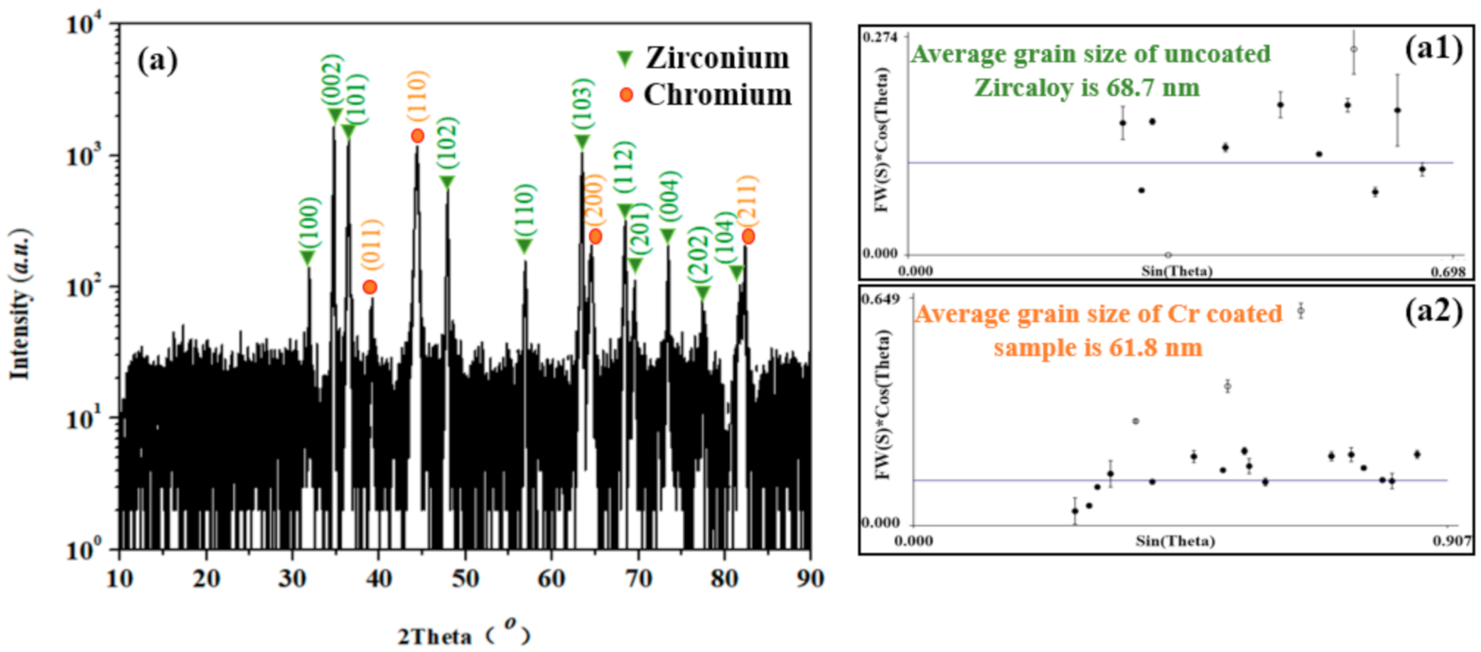
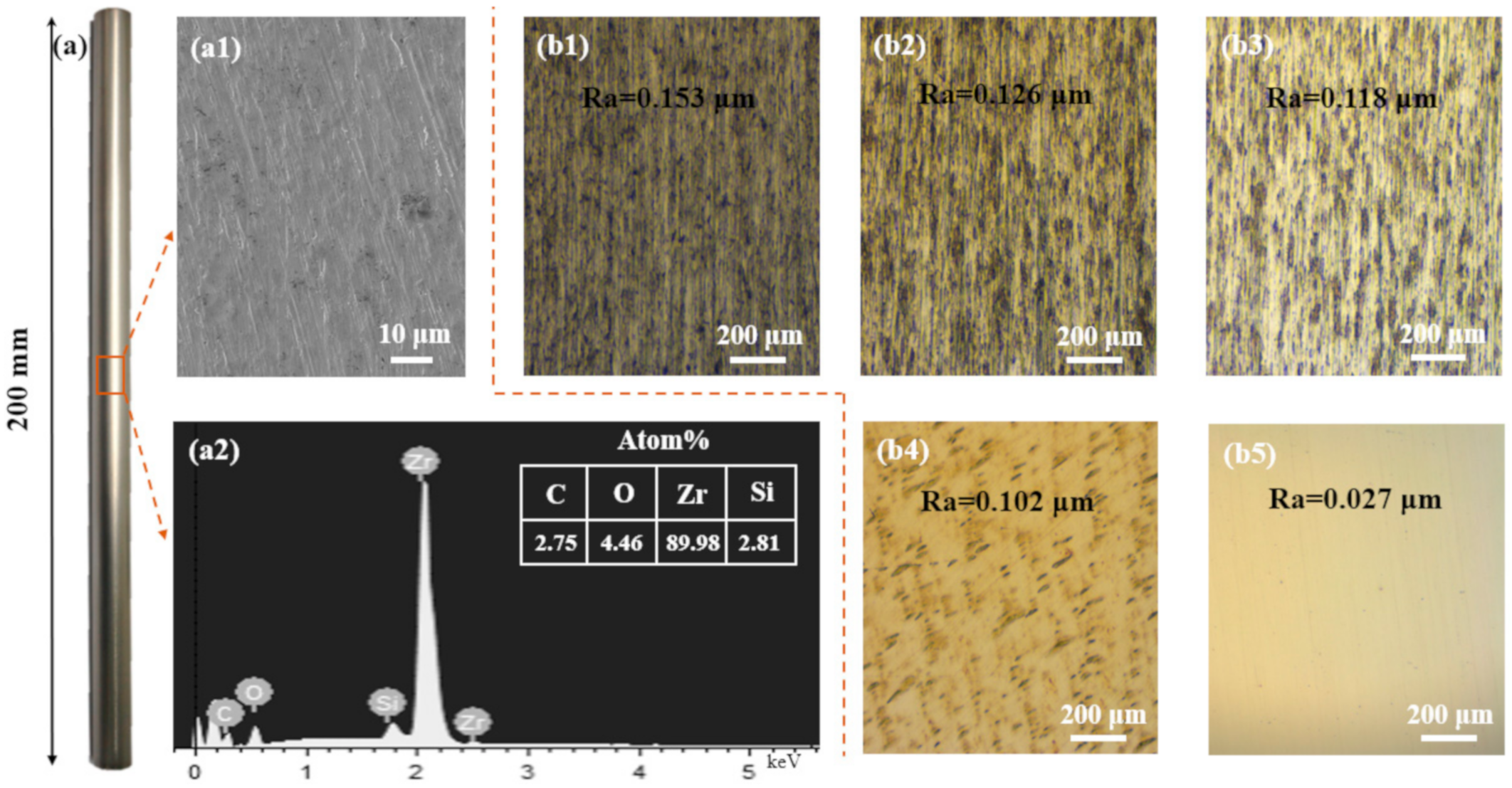
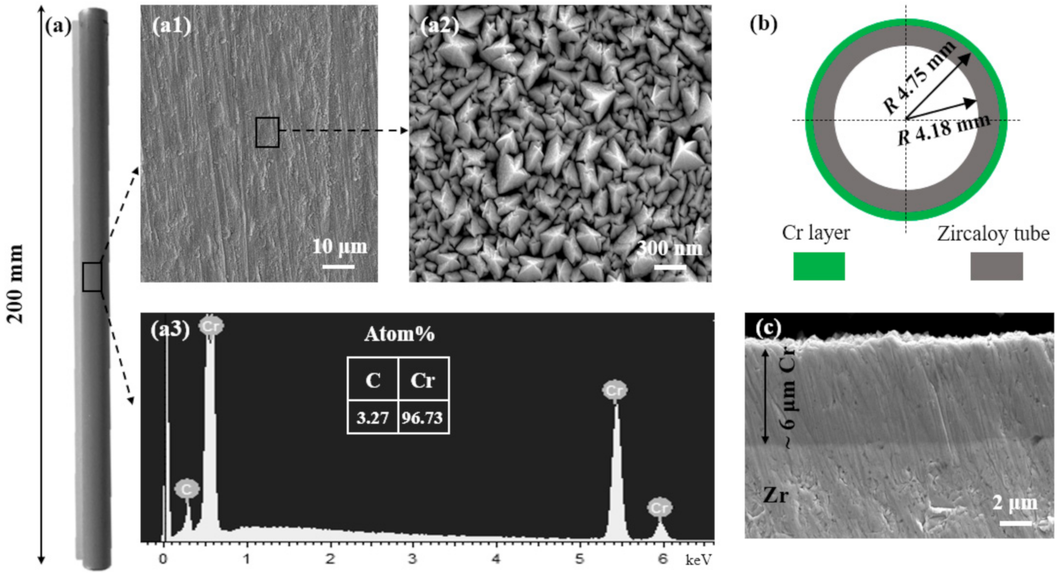
3.1. Morphology Structure and Phase Composition

The XRD patterns of the RF magnetron sputtered Cr coating and the alpha-Zr (PDF card index: 05-0665) substrate were shown in Figure 2a. The peak assignments showed that Cr film was successfully deposited without any alloy phase or compound, and it was conformed to the characteristics of body-centered cubic phase of Cr (PDF card index: 06-0694). As shown in Figure 2(a1,a2), the average grain size of uncoated and Cr-coated specimens were 68.7 nm and 61.8 nm, respectively, suggesting that the dense surface of Cr coating with smaller grain size can improve the anti-oxidation.
Figure 3a shows the macro-morphology of the uncoated zircaloy tube with metallic luster, and its micro-morphology is shown in Figure 3(a1). The Zr element of the uncoated zircaloy was observed clearly (see Figure 3(a2)), and the impurity elements such as Si, O and C were unavoidably mixed by a polishing procedure. The roughness of the zircaloy surface is one of the key influences of the bonding forces between the coatings and the substrates. Roughness was obtained by polishing with the silicon carbide sandpapers with different particle sizes. The optical microscope (OM) images of the zircaloy substrates with the roughness of Ra 0.153 μm (1000 mesh sandpaper), 0.126 μm (2000 mesh sandpaper), 0.118 μm (3000 mesh sandpaper), 0.102 μm (5000 mesh sandpaper) and 0.027 μm (velvet polishing cloth) are shown in Figure 3(b1–b5)).
Figure 4a shows the macro-morphology of the Cr-coated cladding tube, and the surface exhibited a silver-white metallic gloss. As shown in Figure 4(a1,a2), a continuous and dense Cr coating was successfully fabricated on the zircaloy cladding. The elements of the Cr layer were characterized by EDS (see Figure 4(a3)), and the undetectable zirconium element indicated that RF magnetron sputtered Cr coating completely covered the zircaloy cladding without microcracks and voids. The illustration diagram and the SEM image of the cross-section of the Cr-coated tube were shown in Figure 4b,c, respectively.

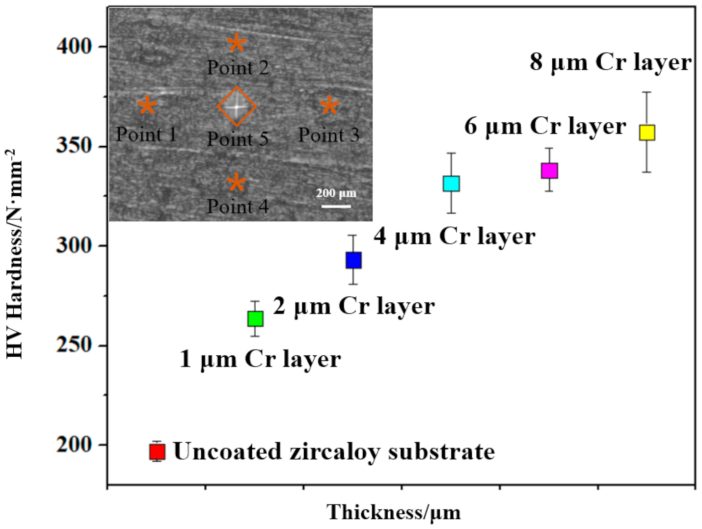
3.2. Mechanical Properties

After the deposition, HV hardness of the specimens was measured by the micro Vickers analysis. Cr coatings with thickness of 1, 2, 4, 6 and 8 μm were deposited for HV hardness performance evaluation. As shown in Figure 5, five sampling points were selected to avoid the errors which were caused by location signal differences, and the hardness of each specimen was the average value. In general, the HV hardness of the specimen increased obviously with increasing the thickness of Cr coatings from 1 to 8 μm. The HV hardness of 8 μm thick sputtered Cr coating reached up to 357.4 N/mm2, which was much higher than the uncoated zircaloy cladding.
As shown in Figure 6, bonding force between the substrates and the coatings raised along with the decline of the surface roughness. However, excessive smooth surface was not conducive to the coating adhesion, and the optimal roughness of the substrates was around Ra 0.102 μm with the bonding force up to 26.3 N/mm2. Yang hui et al. [22] reported that the proper roughness not only made the surface activation and exposed the fresh metal surface, but also led to the surface in a compressive stress state, which was beneficial to the combination of the coating and the substrate. The proper surface roughness can disrupt the direction of the shrinkage force of the coating and reduce the stress along the substrate surface. The relationship between coating thickness and the bonding force is also shown in Figure 6. The specimens deposited with Cr coatings with different thickness were prepared on the surface of zircaloy substrates with roughness of Ra 0.1 μm, and the bonding force of the 6 μm thick Cr coating was up to 42.5 N/mm2. Huang et al. [23] reported that thickness of the coatings has no significant effect on the friction coefficients, but there was an optimization thickness for adhesion between the coatings and the substrate.
The load–displacement curves of the radial tensile specimens at 500 °C were shown in Figure 7. A clear deviation of the displacement curves indicated anti-tensile property of the Cr coating during loading. The displacement of the Cr-coated tensile specimen was 2.32 mm, which was far below the uncoated zircaloy cladding of 3.05 mm. The obvious improvement of tensile property is mainly due to the intrinsic performance of high Young’s modulus of the protective chromium coating [21].

3.3. Oxidation Resistance Properties

The oxidation test was operated at 1200 °C water steam environment for 3000 s for the tube-shape sample with Cr coating only on the outside surface of zircaloy tube, and the weight gain was calculated by the ratio of total weight gain to total exposed area. The weight of the specimens gained obviously with oxidation time, and the degrees of oxidation of all the specimens were approximately followed by an order of uncoated >1 μm Cr-coated >2 μm Cr-coated >4 μm Cr-coated >6 μm Cr-coated and 8 μm Cr-coated specimens. The weight gain of 6 and 8 μm Cr-coated specimen (around 4 mg/cm2) was much lower than that of the uncoated zircaloy (15.53 mg/cm2). Weight gain curves of the uncoated and different thickness of Cr-coated specimens were shown in Figure 8.
After the oxidation, the cross-section images of the specimens were shown in Figure 9. The uncoated zircaloy was severely oxidized and the structure of zircaloy tube was damaged seriously (Figure 9a). The outside and inside walls of the 6 μm Cr-coated zircaloy tube (Figure 9b) were shown in Figure 9(c1,c2), respectively. The inside surface of the cladding sample without Cr coating was also significantly oxidized mainly due to the O element diffusing into the substrate. The larger thickness of the Cr coatings exhibited better oxidation resistance; however, flaws such as holes and cracks often occurred in over-thick coating specimens (see Figure 9d). By the comprehensive consideration of the fabrication process and complex service environment, 6 μm was selected as the ideal thickness for the RF magnetron sputtered Cr coating. With the outer Cr coatings namely 1, 2, 4, 6 and 8 μm, Cr-coated specimens kept the tube structure, and 6 μm Cr-coated specimen showed best oxidation resistance (Figure 9c).
After the oxidation, the distribution and contents of elements of the cross-section significantly changed via analyzing the EDS curves of Zr, O, Cr and C elements (Figure 10a). Mappings of the Cr oxides exhibited uneven surface (see Figure 10b) due to the aggregation particles and the formation of volatile CrO3 and CrO2(OH). The thermodynamic stable Cr2O3 layer played main role of oxidation resistant at high temperature steam environment [24,25,26]. The interface between the Cr coating and zircaloy substrate was disappeared after oxidation, and a chrome-rich zone was formed on the side adjacent to the zircaloy (see Figure 10c,d), which was coincident with the SEM observation (Figure 9(c1)).

4. Conclusions

RF magnetron sputtered Cr coatings can increase the mechanical properties of the zircaloy cladding due to the Young’s modulus of chromium which was higher that of zircaloy, and there exists a positive correlation between the thickness of Cr coatings and HV hardness. The surface with a proper roughness can effectively enhance the bonding force between the coatings and zircaloy substrate, and the roughness of Ra 0.1 μm was optimal for Cr coating. The Cr coating can enhance the anti-deformation performance of the zircaloy cladding, and the displacement of Cr-coated specimens was as low as 2.32 mm at 500 °C, which was much lower than uncoated zircaloy cladding. The RF magnetron sputtered Cr coating significantly promoted the oxidation resistance of the zircaloy cladding under a 1200 °C steam environment. After oxidization for 3000 s, the weight gain of 6 μm Cr-coated specimen (4.12 mg/cm2) was almost one-third of the uncoated zircaloy cladding (15.53 mg/cm2) due to the formation Cr oxides layer. The crystal structure of the outermost oxides and the best coating structure design should be identified in further research.

Author Contributions

Conceptualization, G.L., Y.L. (Yanhong Liu) and Y.Z.; data curation, G.L. and M.Z.; formal analysis, G.L.; project administration, X.W.; resources, H.L.; writing—original draft, G.L. and Y.L. (Yusha Li); writing—review & editing, G.L. All authors have read and agreed to the published version of the manuscript.

Funding

This work was supported by National Science and Technology Major Project of China (NO.2015ZX06004001-002) and Beijing Municipal Commission of Science and Technology Foundation (NO. Z181100005218005).

Conflicts of Interest

The authors declare no conflict of interest.

References

  1. Terrani, K.A. Accident tolerant fuel cladding development: Promise, status, and challenges. J. Nucl. Mater. 2018, 501, 13–30. [Google Scholar] [CrossRef]
  2. Kimura, A.; Kasada, R.; Iwata, N.; Kishimoto, H.; Zhang, C.H.; Isselin, J.; Dou, P.; Lee, J.H.; Muthukumar, N.; Okuda, T.; et al. Development of Al added high-Cr ODS steels for fuel cladding of next generation nuclear systems. J. Nucl. Mater. 2011, 417, 176–179. [Google Scholar] [CrossRef]
  3. Sidelev, D.V.; Kashkarov, E.B.; Syrtanov, M.S.; Krivobokov, V.P. Nickel-chromium (Ni–Cr) coatings deposited by magnetron sputtering for accident tolerant nuclear fuel claddings. Surf. Coat. Technol. 2019, 369, 69–78. [Google Scholar] [CrossRef]
  4. Duan, Z.; Yang, H.; Satoh, Y.; Murakami, K.; Kano, S.; Zhao, Z.; Shen, J.; Abe, H. Current status of materials development of nuclear fuel cladding tubes for light water reactors. Nucl. Eng. Des. 2017, 316, 131–150. [Google Scholar] [CrossRef]
  5. Hallstadius, L.; Johnson, S.; Lahoda, E. Cladding for high performance fuel. Prog. Nucl. Energy 2012, 57, 71–76. [Google Scholar] [CrossRef]
  6. Cheng, B.; Kim, Y.J.; Chou, P. Improving accident tolerance of nuclear fuel with coated Mo-alloy cladding. Nucl. Eng. Technol. 2016, 48, 16–25. [Google Scholar] [CrossRef] [Green Version]
  7. Kim, I.; Khatkhatay, F.; Jiao, L.; Swadener, G.; Cole, J.I.; Gan, J.; Wang, H. TiN-based coatings on fuel cladding tubes for advanced nuclear reactors. J. Nucl. Mater. 2012, 429, 143–148. [Google Scholar] [CrossRef]
  8. Kuprin, A.S.; Belous, V.A.; Voyevodin, V.N.; Bryk, V.V.; Vasilenko, R.L.; Ovcharenko, V.D.; Reshetnyak, E.N.; Tolmachova, G.N.; V’yugov, P.N. Vacuum-arc chromium-based coatings for protection of zirconium alloys from the high-temperature oxidation in air. J. Nucl. Mater. 2015, 405, 400–406. [Google Scholar] [CrossRef]
  9. Daub, K.; van Nieuwenhove, R.; Nordin, H. Investigation of the impact of coatings on corrosion and hydrogen uptake of Zircaloy-4. J. Nucl. Mater. 2015, 467, 260–270. [Google Scholar] [CrossRef]
  10. Alat, E.; Motta, A.T.; Comstock, R.J.; Partezana, J.M.; Wolfe, D.E. Multilayer (TiN, TiAlN) ceramic coatings for nuclear fuel cladding. J. Nucl. Mater. 2016, 478, 236–244. [Google Scholar] [CrossRef] [Green Version]
  11. Foroughi-Abari, A.; Xu, C.; Cadien, K.C. The effect of argon pressure, residual oxygen and exposure to air on the electrical and microstructural properties of sputtered chromium thin films. Thin Solid Film. 2012, 520, 1762–1767. [Google Scholar]
  12. Wang, Y.; Zhou, W.; Wen, Q.; Ruan, X.; Luo, F.; Bai, G.; Qing, Y.; Zhu, D.; Huang, Z.; Zhang, Y.; et al. Behavior of plasma sprayed Cr coatings and FeCrAl coatings on Zr fuel cladding under loss-of-coolant accident conditions. Surf. Coat. Technol. 2018, 344, 141–148. [Google Scholar]
  13. Su, R.; Zhang, H.; Meng, X.; Shi, L.; Liu, C. Synthesis of Cr2AlC thin films by reactive magnetron sputtering. Fusion Eng. Des. 2017, 125, 562–566. [Google Scholar]
  14. Pedersen, K.; Bøttiger, J.; Sridharan, M.; Sillassen, M.; Eklund, P. Texture and microstructure of Cr2O3 and (Cr,Al)2O3 thin films deposited by reactive inductively coupled plasma magnetron sputtering. Thin Solid Film. 2010, 518, 4294–4298. [Google Scholar]
  15. Kim, H.G.; Kim, I.H.; Jung, Y.I.; Park, D.J.; Park, J.Y.; Koo, Y.H. Adhesion property and high-temperature oxidation behavior of Cr-coated Zircaloy-4 cladding tube prepared by 3D laser coating. J. Nucl. Mater. 2015, 465, 531–539. [Google Scholar]
  16. Kuprin, A.S.; Belous, V.A.; Voyevodin, V.N.; Vasilenko, R.L.; Ovcharenko, V.D.; Tolstolutskaya, G.D.; Kopanets, I.E.; Kolodiy, I.V. Irradiation resistance of vacuum arc chromium coatings for zirconium alloy fuel claddings. J. Nucl. Mater. 2018, 510, 163–167. [Google Scholar]
  17. Kane, K.A.; Stack PI, M.; Mouche, P.A.; Pillai, R.R.; Pint, B.A. Steam oxidation of chromium corrosion barrier coatings for sic-based accident tolerant fuel cladding. J. Nucl. Mater. 2020, 543, 152561. [Google Scholar]
  18. Ševeček, M.; Gurgen, A.; Seshadri, A.; Che, Y.; Wagih, M.; Phillips, B.; Champagne, V.; Shirvan, K. Development of Cr cold spray–coated fuel cladding with enhanced accident tolerance. Nucl. Eng. Technol. 2018, 50, 229–236. [Google Scholar]
  19. Hu, X.; Dong, C.; Wang, Q.; Chen, B.; Yang, H.; Wei, T.; Zhang, R.; Gu, W.; Chen, D. High-temperature oxidation of thick Cr coating prepared by arc deposition for accident tolerant fuel claddings. J. Nucl. Mater. 2019, 519, 145–156. [Google Scholar]
  20. Chen, Q.S.; Liu, C.H.; Zhang, R.Q.; Yang, H.Y.; Wei, T.G.; Wang, Y.; Li, Z.; He, L.X.; Wang, J.; Wang, L.; et al. Microstructure and high-temperature steam oxidation properties of thick Cr coatings prepared by magnetron sputtering for accident tolerant fuel claddings: The role of bias in the deposition process. Corros. Sci. 2020, 165, 108378. [Google Scholar]
  21. Li, G.; Liu, Y.; Zhang, Y.; Li, H.; Wang, X.; Zheng, M. Oxidation behavior of RF magnetron sputtered Cr-SiC-Cr composites coating on zircaloy fuel cladding. Mater. Res. Express 2019, 6, 096434. [Google Scholar]
  22. Yang, H.; Pan, S. Effect of Substrate Surface Roughness on Bond Strength of Coatings. Hot Work. Technol. 2008, 37, 118–121. [Google Scholar] [CrossRef]
  23. Hung, W.; Liu, M.; Li, Z.; Zeng, R. Thickness effects on corrosion and wear resistance properties of micro-arc discharge oxide coatings on AZ91D magnesium alloys. Trans. Nonferrous Met. Soc. China 2006, 16, 1827–1830. [Google Scholar]
  24. Yeom, H.; Maier, B.; Johnson, G.; Dabney, T.; Lenling, M.; Sridharan, K. High temperature oxidation and microstructural evolution of cold spray chromium coatings on Zircaloy-4 in steam environments. J. Nucl. Mater. 2019, 526, 151737. [Google Scholar]
  25. Wang, T.G.; Jeong, D.; Liu, Y.; Wang, Q.; Iyengar, S.; Melin, S.; Kim, K.H. Study on nanocrystalline Cr2O3 films deposited by arc ion plating: II. Mechanical and tribological properties. Surf. Coat. Technol. 2012, 206, 2638–2644. [Google Scholar]
  26. Barshilia, H.C.; Rajam, K.S. Growth and characterization of chromium oxide coatings prepared by pulsed-direct current reactive unbalanced magnetron sputtering. Appl. Surf. Sci. 2008, 255, 2925–2931. [Google Scholar]
Figure 1. The illustration diagram of zircaloy cladding radial tensile test.
Metals 10 01509 g001
Figure 2. XRD patterns of (a) the Cr-coated zircaloy cladding. (a1) The average grain size of the uncoated zircaloy cladding. (a2) The average grain size of the Cr-coated zircaloy cladding.
Metals 10 01509 g002
Figure 3. Morphology and Energy dispersive spectroscopy (EDS) of the uncoated zircaloy tube, and the OM images of the zircaloy substrates with different roughness: (a) The macro-morphology of zircaloy tube with dimensions of 200 mm in length. (a1) The micro-morphology of the uncoated zircaloy tube. (a2) EDS element analysis of the zircaloy. (b1b5) OM images of the uncoated zircaloy claddings with different roughness.
Metals 10 01509 g003
Figure 4. Morphology and EDS of 6 μm Cr-coated specimens: (a) The macro-morphology of Cr-coated zircaloy tube. (a1,a2) The micro-morphology of the Cr coating with different magnification. (a3) EDS elements characterization of the Cr-coated specimen. (b) The illustration diagram of the cross-section of Cr-coated zircaloy tube. (c) SEM image of the cross-section of 6 μm Cr-deposited specimen.
Metals 10 01509 g004
Figure 5. HV-hardness of Cr-coated zircaloy claddings with different thickness.
Metals 10 01509 g005
Figure 6. The bonding force between the coatings with different thickness and the substrates with different roughness.
Metals 10 01509 g006
Figure 7. Load–displacement curves of uncoated and Cr-coated zircaloy tubes at 500 °C.
Metals 10 01509 g007
Figure 8. Weight gain curves of the uncoated and different thickness of Cr-coated specimens at 1200 °C for 3000 s.
Metals 10 01509 g008
Figure 9. The morphology and structure of cross-section of the specimens before and after oxidation: (a) uncoated, (b) illustration diagram of Cr-coated zircaloy cladding tube, (c) 6 μm Cr-coated zircaloy cladding, (c1) outside wall of the Cr-coated specimen, (c2) inside wall of the Cr-coated specimen, (d) 8 μm Cr-coated zircaloy cladding tube.
Metals 10 01509 g009
Figure 10. Distribution of cross-section elements analysis by (a) EDS and (bd) Mappings.
Metals 10 01509 g010
Publisher’s Note: MDPI stays neutral with regard to jurisdictional claims in published maps and institutional affiliations.

