Abstract
This paper studies the weld interface microstructure and mechanical properties of AlMg6-stainless steel and AlMg6-titanium bimetals produced using explosive welding. The microhardness (HV), tear strength, and microstructure of the weld seams were evaluated. The interface of the weld zones had a flat profile. No structural disturbances or heterogeneity in the AlMg6-titanium weld interface were observed. On the other hand, the bimetal AlMg6-stainless steel had extensive zones of cast inclusions in the 10–30 µm range. SEM/energy-dispersive X-ray spectroscopy (EDS) analysis showed the presence of a hard and brittle intermetallic compound of Al and FeAl3 (with 770–800 HV). The microhardness of the AlMg6-titanium bimetal grew higher closer to the weld interface and reached 207 HV (for AlMg6) and 340 HV (for titanium). Both bimetals had average tear strength below 100 MPa. However, the tear strength of some specimens reached 186 and 154 MPa for AlMg6-titanium and AlMg6-stainless steel, respectively. It is also worth mentioning that heat treatment at 200 °C for one hour led to a uniform distribution of tear strength along the entire length of the bimetals. The study shows that one of the possible solutions to the problem of the formation of the brittle intermetallic compounds would be the use of intermediate layers of refractory metals.
1. Introduction
Aluminum and its alloys are widely used in marine construction and offshore structures [1]. The use of aluminum alloys makes it possible to reduce the weight of various constructions [2,3]. At present, bimetallic transition joints are used, which allow welding aluminum alloy parts and superstructures to the hulls of ships, railway wagons, or fuselages of aircraft [4]. Their use increases deadweight tonnage and improves the overall ship performance. In addition, aluminum alloys have high corrosion resistance [5].
The welding of aluminum alloys to steel poses a number of significant problems. These problems are mainly caused by the formation of brittle FexAly intermetallic compounds at the weld interface [6,7,8], the difference in the melting points of the two metals and their oxides, the difference in their physical properties, dissimilar thermal expansion, etc. Aluminum oxide (Al2O3) is a highly adhesive and rapid-forming oxide that gives aluminum its excellent corrosion resistance. Aluminum oxide has a very high melting point—2060 °C compared with pure metal, which melts at 660 °C [9]. All these features make it difficult to weld aluminum alloys to steels. There are four basic methods for bimetal production: cold/hot/vacuum rolling, diffusion welding, friction welding, and explosive welding (EW) [8,9,10,11].
Aluminum alloy-steel bimetallic sheets are produced using interlayers of pure aluminum, titanium, chromium, etc. [10,12,13,14,15,16]. The tear strength values of the seams lie within the 80–120 MPa range. These interlayers are widely used both in EW and in rolling of metals and alloys that form brittle intermetallic compounds. These interlayers serve as a diffusion barrier, which prevents the formation of structural heterogeneities.
EW is a solid-state process that makes use of the high energy of explosives to weld dissimilar metal parts without fusion [17,18]. EW causes the plastic deformation of the metal parts and the heating of the contact surfaces [19]. This produces local pockets of intermetallic compounds, which during further heat treatment or fusion welding can grow several times in size and have a negative impact on the strength of the bimetal.
During EW, melting phases with high fusibility could also precipitate from alloys. They reduce the strength properties of the bimetal and have a negative influence on the weld seam. The authors [20] noted that during the EW of brass to steel, the welded surfaces are heated to 1000 °C or above which extracts Zn from the solid solution. The same happens during the EW of bronze [21]. All these circumstances make it necessary to obtain AlMg6-stainless steel bimetals without an intermediate layer or with a layer that would increase the strength of the bimetals, bringing it closer to that of the aluminum alloy. The EW of titanium to aluminum and aluminum alloys poses a number of problems caused by the formation of Al3Ti and AlTi intermetallic compounds, the metastable phases of Al5Ti3, amorphous structures, and solid solutions along the weld interface [22,23]. A study [24] showed that at a detonation velocity of 2500–2700 m/s and an impact velocity of 530–560 m/s, films of titanium oxides and aluminum oxides with a substantial number of defects form at the Ti-Al interface. Another study [25] showed that long annealing at a temperature of 903 K for 100 h of Al-Ti-Al in a vacuum causes intermetallic compounds to grow on both surfaces. In [26], the EW of titanium Grade 1 to aluminum alloy AW7075 arranged in a parallel setup was performed. Subsequent annealing at 450, 500, and 550 °C for 20 to 100 h was carried out after explosive welding. After annealing, a Al18Ti2Mg3 intermetallic compound layer was observed at the interface. A higher annealing temperature and longer holding increase the thickness of the intermetallic compound up to an average of 13 µm. If the kinetic energy and the heating of the surfaces due to shock-compressed air are high enough, a melting zone can appear at the weld interface [27,28]. Its thickness depends on the amount of kinetic energy and heating. The last factor is especially important for the EW of titanium, because titanium particles burn in the air present in the welding gap, which has a negative effect on the mechanical properties of the weld [29]. Studies [30,31] showed examples of EW of Ti6Al4V to AA2519, with and without an interlayer of AA1050. The results showed that EW is an effective method of producing Ti6Al4V-AA2519 bimetals without defects. Al3Ti and Al2Ti form at the weld interface. Their thickness increases when an aluminum interlayer was used.
The EW of aluminum alloys to stainless steels is a pressing issue in materials science at the moment. One study [32] examined the influence of the explosive ratio R (the mass of the explosive/the mass flyer plate) on the properties of the weld interface of Al5052-SS316. The authors showed that the bigger R is, the higher pressure and kinetic energy. The numerical simulations and metallographic studies showed that the optimal value of R is 0.8. In [33], the EW of S355J2 + N steel-aluminum AA1050-AA5083 aluminum alloys was performed. Then, the study of the impact of subsequent fusion welding on the properties of this bimetal was carried out. It was shown that fusion welding causes a softening of the alloys. However, the softening of AA5083 and AA1050 layers did not affect the strength of the welded structural joints. The features of the weld interface of Al1100-low-carbon steel were examined in [34]. Two types of intermediate layers (Al3Fe and Al5Fe2) formed at the wavy joint interface produced at an impact velocity of 750 m/s and a collision angle of 15°. A new method of EW of 5083 aluminum alloy to Q345 steel was studied in [35], where dovetail grooves were employed. The parameters adopted in the explosive welding experiment were close to the lower limit of a weldable window of 5083 aluminum alloy to Q345 steel. The average tensile strength of the bimetal was higher than that of 5083 aluminum alloy. Energy-dispersive X-ray spectroscopy (EDS) and X-ray diffraction (XRD) analyses showed the presence of the brittle intermetallic compounds FeAl2 and Al5Fe2. In study [36], explosive welding was used in the cladding of aluminum plates to ship steel plates at different explosive ratios (R = 2, R = 2.5, R = 3, and R = 3.5). The scanning electron microscope (SEM) and EDS investigations on the ship steel-aluminum bimetal composite joining interface revealed that a flat interface was obtained at a low explosive ratio and no intermetallic compound was observed, but as the explosive ratio increased, a wavy structure was formed by mechanical interlocking at the interface, and some intermetallic compounds (FeAl3 + αAl and α2) were formed. Tensile-shear tests of ship steel-aluminum bimetal composite samples showed that the tensile-shear strength increased at increasing explosive ratios.
This review of previous works shows that most studies of EW were conducted for aluminum alloys with Mg content less than 5%. The EW of AlMg6 to stainless steel and to titanium is understudied. The optimal parameters for this type of welding should be obtained. Their influence on the properties of the weld interface and mechanical properties along the whole lengths of bimetal samples should be evaluated. The use of aluminum interlayers limits substantially the ultimate tensile strength, which prevents the use of bimetallic transition joints for structures with high tensile strength requirements. This study aims to obtain bimetallic transition joints AlMg6-08Cr18Ni10Ti and AlMg6-titanium using EW without interlayers and to examine the properties of the weld interface along the entire length of the bimetal. This study is the first step in developing strong and high-quality transition joints for marine shipbuilding, train wagon building, and automotive industry. The results obtained in the paper serve as the basis for further studies in the field.
2. Materials and Methods
2.1. Materials
Sheets of aluminum alloy AlMg6, titanium, and stainless steel 08Cr18Ni10Ti were used. The chemical composition is given in Table 1. Table 2 shows the dimensions and thicknesses of the initial materials. These dimensions are adequate and allow studying the conditions of the weld formation during EW. The dimensions were also chosen based on the actual sizes of bimetal transition joints used at the moment in various fields.

Table 1.
The chemical composite (wt %) of initial materials.

Table 2.
Dimensions and thicknesses of initial materials.
2.2. Explosive Welding Process
The setup of the experiments is shown in Figure 1. Before assembling, the surfaces of the plates were cleaned from oxide films and rust. The external surfaces were covered with a layer of PE film. Explosive 4 is a 96:4 mixture of microporous ammonium nitrate (Acron Group, Velikiy Novgorod, Russia) and diesel oil (d = 780 kg/m3). The layer of explosive was spread over the assembly, placed in a single-use formwork, and exploded with detonator 3. The detonation velocities of AlMg6 + titanium and AlMg6 + stainless steel were 1600 m/s and 1700 m/s, respectively. The thicknesses of the explosive were 25 mm and 32 mm. The stand-off distance between the flyer plate and parent plate was about 6 mm. The EW parameters were chosen based on the analysis of the data found in research works on EW of titanium and steel to aluminum alloys [20,24,32] and from the authors’ own practical experience in the field. The EW parameters were calculated from empirical equations [18,37,38].
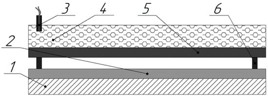
Figure 1.
Basic setup for explosive welding (EW): 1—anvil, 2—parent plate (AlMg6), 3—detonator, 4—explosive, 5—flyer plate (Titanium/08Cr18Ni10Ti), 6—support.
2.3. Microstructural Study
Before the metallographic study, the metallographic specimens were cleaned, ground, and finished. After ultrasound testing, the specimens were cut in half lengthways. One of the halves underwent heat treatment. The tear strength specimens and metallographic specimens were prepared according to Figure 2. Arrow D shows the detonation direction from the welding point to the other edge of the bimetal. Along the whole lengths of the sheets, from the welding point to the end, 11 tear strength specimens were made from each of the halves, creating a total of 22 specimens for a sheet. It was made to get a picture of the strength distribution along the entire length of the bimetal, not for certain areas only.
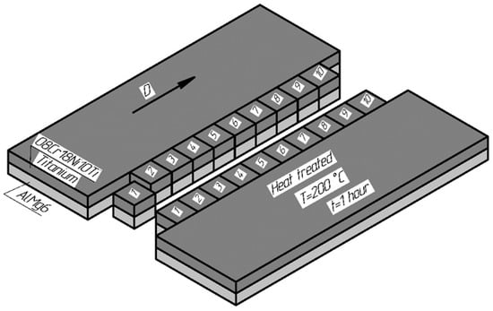
Figure 2.
Preparation of tear strength specimens.
Microstructural studies of the weld interface were carried out with a METAM LB34 optical microscope and a camera TS-500 (LOMO-Microsystems, St. Petersburg, Russia). The longitudinal cross-section of the bimetals was examined using a ShLIF-1M/V setup (STC Expert, Moscow, Russia). SEM/EDS analysis was carried out with a Zeiss Ultraplus microscope equipped (Carl Zeiss Microscopy, Oberkochen, Germany) with an INCA 350 Oxford accessory (Oxford Instruments, United Kingdom)
2.4. Mechanical Test
PMT-3 tester (LOMO-Microsystems, St. Petersburg, Russia) and MMS software were used to study the microhardness (HV) distribution of the welded layers. A load of 50 g was applied for 15 s. Microhardness was measured for two specimens from each of the sheets. There were three equally spaced measurement lines for each of the specimens over the entire thickness. The tear test was conducted with an Instron 1195 (Instron Ltd., High Wycombe, UK), as shown in Figure 3a. The specimen for the tear strength test is shown in Figure 3b. According to technical specifications 27.32.09.010-2005, the tear strength σt was calculated from the following equation:
where P is the applied load (in H), d1 = 15 ± 0.005 mm, d2 = 19 ± 0.005 mm.
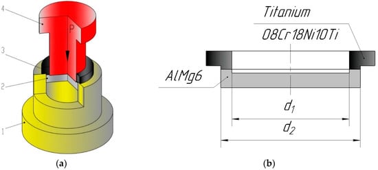
Figure 3.
Tear test diagram (a): (1) mold, (2) AlMg6, (3) titanium/stainless steel, (4) male die; (b) tear strength specimen.
The procedure for the test was as follows. (1) The specimen was installed into mold (1). Then, through male die (4), the load P was transmitted from an Instron 1195 machine to the specimen, until the tearing of layer (3) from layer (2) occurred. Then, from Equation (1), the tear strength was calculated.
To analyze the delamination resistance of the bending interface, bending tests of AlMg6-titanium and AlMg6-08Cr18Ni10Ti composite plates were conducted. The tests were conducted according to GOST 14019-2003 in an Instron 1195 machine at an angle of 120° under normal conditions. The load was applied at the central point between the two supports of the plate. There should not be any cracks or delamination at the point of the bending of the plates. The specimens were cut from the central part of the bimetal along the plane parallel to the detonation direction. The specimens’ dimensions were 5 mm (height), 20 mm (width), and 130 mm (length).
An ultrasonic test was conducted using a UD2V-P45 apparatus (CROPUS, Noginsk, Russia) with two separately combined converters (P112-2.5 and P112-5). Heat treatment of the specimens was conducted in a muffle furnace SNOL 8,2/1100 (Umega Group, Utena, Lithuania) at 200 °C and for one hour.
3. Results and Discussion
Figure 4 shows the bimetal sheet after EW. Ultrasound testing showed good, practically 100% continuity of weld seam across the entire sheet surface, except for some rim zones.
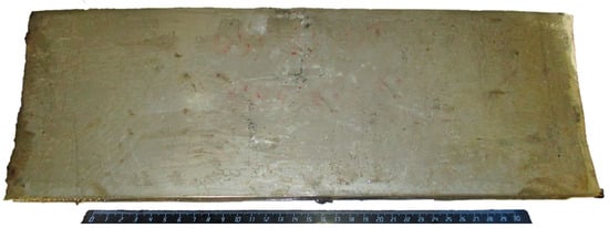
Figure 4.
Bimetal sheet after EW.
3.1. Study of AlMg6-Titanium Bimetal
The morphology of the interface zones after EW is shown in Figure 5. The interface zone was flat along the entire length of the bimetal. The weld seam of AlMg6-titanium did not have any defects. Since the deformation caused by EW was minimal, the structure of the weld interface remained the same. The reason for this is that the value of the specific kinetic energy transformed into the plastic deformation of surface metal layers (W2) was relatively low [39].

Figure 5.
SEM micrographs: (a) the weld interface beside the welding point; (b) the weld interface of the other edge of the bimetal.
In order to estimate the change in the mechanical property of the bimetal, the microhardness of the cross-section specimens was measured. Figure 6 shows the microhardness distribution near the AlMg6-titanium weld seam after the EW and the heat treatment.
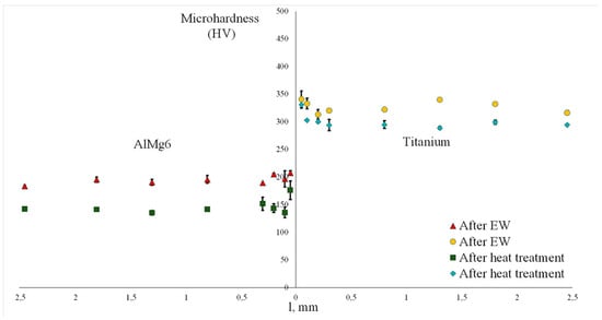
Figure 6.
Microhardness of AlMg6-titanium weld interface.
The microhardness of the AlMg6-titanium bimetal increased closer to the weld interface and reached 207 HV (for AlMg6) and 340 HV (for titanium). It happens because the grains of the welded materials experience deformation and fining during EW [40]. Moreover, residual stresses increase the strength closer to the weld interface because of the differences in the thermal-physical properties of aluminum alloys and titanium [41]. By releasing residual stress, heat treatment decreased the average microhardness of the AlMg6 alloy by 30% from 196 to 140 HV and the microhardness of the titanium by 10% from 332 to 304 HV.
The tear specimens shown in Figure 7 were made according to technical specifications 27.32.09.010-2005. The tear strength values of the specimens cut from AlMg6-titanium bimetal are shown in Figure 8. The average tear strength of the weld seam after EW was 94 MPa. However, starting at a distance of 180 mm from the point where the welding started to the other edge of the bimetal, the tear strength was higher. The average tear strength of this segment was 131 MPa. The maximum tear strength of a specimen cut out at a distance of 180 mm from the welding point was as high as 186 MPa. The irregular pattern of the strength distribution is caused by residual stresses after EW. Residual stresses form due to inhomogeneous temperature distributions. When cooling, welded metals tend to expand to their initial sizes, which can produce high tensile stresses. For dissimilar metals, residual stresses can be even higher due to the difference in elastic, mechanical properties, and in thermal expansion coefficients [42].

Figure 7.
Tear strength specimens.
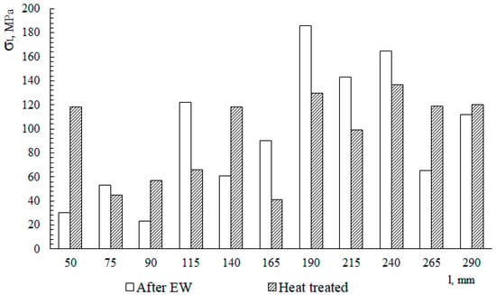
Figure 8.
The tear strength values distribution along the bimetal sheet.
After heat treatment, the average tear strength was also 94 MPa, but the strength distribution was more uniform along the length of the specimen. Again, starting at a distance of 180 mm from the welding point and to the other edge of the bimetal, the tear strength was higher. The average tear strength of this segment was 121 MPa. The uniform distribution of mechanical properties is due to the release of residual stresses during heat treatment. It shows that the heat treatment parameters were chosen correctly.
3.2. Study of AlMg6-08Cr18Ni10Ti Bimetal
The weld seam of AlMg6-08Cr18Ni10Ti had a flat profile (Figure 9a). In the end areas, extensive zones of cast inclusions in the 10–30 µm range composed of Fe-Al intermetallic compounds range were observed (Figure 9b). They formed because of the high temperature of the shock-compressed gas formed in the welding gap during EW. They do not form at the head end due to the instability of the thermodynamic parameters of the shock-compressed gas [43]. The low melting point of Al leads to a large amount of molten Al, which reacts with Fe to form FexAly intermetallic compounds [12,27,44,45].

Figure 9.
SEM micrographs: (a) the weld interface beside the welding point; (b) the weld interface the other edge of the bimetal.
Figure 10 shows the concentration profiles of Al, Mg, Ni, Fe, Cr, Si, and Mn in the stainless steel, AlMg6 alloy, and the weld interface. The line scan shows a thin intermetallic layer. The intermetallic layer consisted of Fe, Al, Mg, and Cr, and it had thickness in the 10–30 µm range.
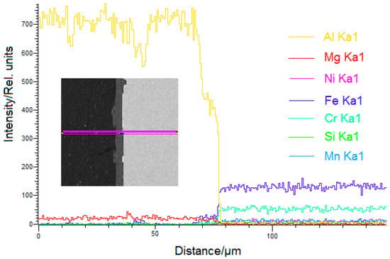
Figure 10.
Energy-dispersive X-ray spectroscopy (EDS) results.
Figure 11 shows the SEM micrograph of the AlMg6-08Cr18Ni10Ti weld interface. Based on the Fe-Al phase diagram and our EDS results, we concluded that the cast inclusion layer was composed of Al and FeAl3. The EDS also showed the presence of the elements of 08Cr18Ni10Ti steel (Table 3). They appear when solid particles diffuse from the welded alloys into the molten metal at the weld interface and then crystallize rapidly. This hinders the diffusion of Fe into Al.
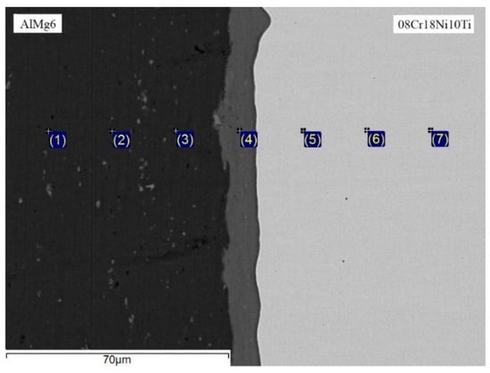
Figure 11.
SEM image for AlMg6-08Cr18Ni10Ti weld interface.

Table 3.
EDS results for AlMg6-08Cr18Ni10Ti interface (all results in wt %).
The microhardness distribution of AlMg6-08Cr18Ni10Ti weld seam are shown in Figure 12. The microhardness of the steel increased closer to the weld interface and reached 420 HV. It happens because of the summary of residual stresses in stainless steel. The microhardness of AlMg6 did not change over the entire thickness of the sample. By releasing residual stress, the heat treatment decreased the average microhardness of the stainless steel by 10% from 412 to 373 HV.
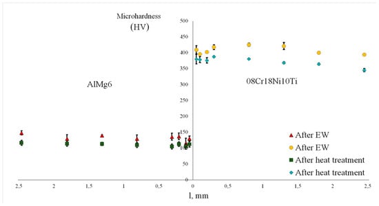
Figure 12.
Microhardness of AlMg6-08Cr18Ni10Ti weld interface.
The tear strength values of the specimens cut out from AlMg6-8Cr18Ni10Ti bimetal are shown in Figure 13. The average tear strength of the weld seam after EW was 45 MPa. The maximum tear strength of a specimen cut out at a distance of 290 mm from the head end was as high as 110 MPa.
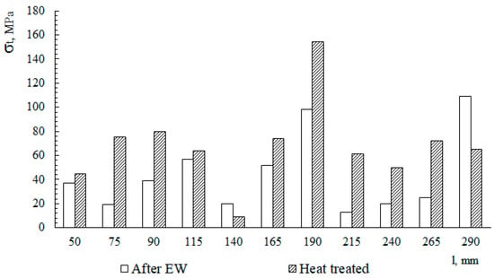
Figure 13.
The tear strength values distribution along the bimetal sheet.
After heat treatment, the average tear strength was also 45 MPa, but the strength distribution was more uniform along the length of the specimen. Again, starting at a distance of 180 mm from the head end and through the tail end of the bimetal, the tear strength had bigger values. The average tear strength of the segment was 70 MPa. The maximum tear strength of a specimen cut out at a distance of 180 mm from the head end was as high as 154 MPa. The uniform distribution and increasing of mechanical properties is due to the release of residual stresses during heat treatment. It shows that the parameters were calculated accurately.
When bending a bimetal plate, the most crucial factor is a sudden increase of stresses at the weld interface. As the quality of bimetals is determined by the properties of the weld interface, bending tests of the bimetal plates were conducted. The way the bending tests were conducted reproduces the stresses that occur during the actual operation of bimetal structures, which allows them to be used to evaluate the properties of bimetal materials. The macrograph of the bimetal specimens after bending is shown in Figure 14.
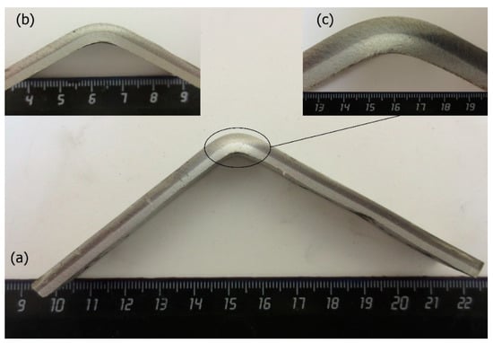
Figure 14.
Macrograph of explosively welded bimetal plate after bending (120°): (a) general view; (b) AlMg6-titanium specimen; (c) AlMg6-08Cr18Ni10Ti specimen.
To analyze the delamination resistance of the bending interface, the bending properties of the AlMg6-08Cr18Ni10Ti composite plate were studied. After bending at 120°, the specimens showed resistance to delamination. Cracks were not observed either, which indicates the satisfactory quality of the EW.
4. Conclusions
(1) Using EW, we produced bimetal sheets with a cladding layer of AlMg6 alloy. We found that the low deformation caused by EW and the FeAl3 intermetallic compound layer resulted in the low strength of the AlMg6-08Cr18Ni10Ti weld seam. Therefore, it is necessary to increase the welding modes for AlMg6-titanium. However, this may produce even larger layers of brittle intermetallics. Therefore, one of the possible solutions would be the use of intermediate layers of refractory metals that do not form intermetallic compounds with welded metals: for example, molybdenum, vanadium, and titanium.
(2) The fact that the microhardness and tear strength of the specimens became more uniform after the heat treatment shows that the parameters of the heat treatment were chosen correctly. The heat treatment at 200 °C releases residual stresses formed after EW and makes the tear strength of the bimetal more uniform across the whole area of the weld joint.
(3) The maximum tear strength of AlMg6-titanium and AlMg6-08Cr18Ni10Ti was at a distance of 180–190 mm from the point where the welding started. Therefore, with these parameters of welding, the tear strength of AlMg6-titanium and AlMg6-08Cr18Ni10Ti is lower at distances from 0 to 180 mm from the welding point.
(4) A bending test showed that the bimetals are resistant to delamination at an angle of 120°, which indicates the satisfactory quality of the weld seams.
Author Contributions
A.Y.M. conceived and designed the experiments and wrote the paper; I.V.S. performed the experiments and analyzed the experimental data; I.V.D. designed and carried out explosive welding experiments and wrote the paper; N.N.N. performed the experiments and carried out explosive welding experiments. All authors have read and agreed to the published version of the manuscript.
Funding
This work was carried out in the framework of governmental program for ISMAN (topic no. 45.4).
Conflicts of Interest
The authors declare no conflict of interest.
References
- Starke, E.A.; Rashed, H.M.M.A., Jr. Alloys: Aluminum. Ref. Modul. Mater. Sci. Mater. Eng. 2017, 18–24. [Google Scholar] [CrossRef]
- Pesin, A.M.; Pustovoytov, D.O.; Steblyanko, V.L.; Fedoseev, S.A. Physical and computer simulation of severe plastic deformations on shear-compression testing of AMg6 aluminum alloy. Non Ferr. Met. 2017, 42, 17–21. [Google Scholar] [CrossRef]
- Sun, J.; Yan, Q.; Li, Z.; Huang, J. Effect of bevel angle on microstructure and mechanical property of Al/steel butt joint using laser welding-brazing method. Mater. Des. 2016, 90, 468–477. [Google Scholar] [CrossRef]
- Becker, N.; Gauthier, D.; Vidal, E.E. Fatigue Properties of Steel to Aluminum Transition Joints Produced by Explosion Welding. Int. J. Fatigue 2020, 139, 105736. [Google Scholar] [CrossRef]
- Wahid, M.A.; Siddiquee, A.N.; Khan, Z.A. Aluminum alloys in marine construction: Characteristics, application, and problems from a fabrication viewpoint. Mar. Syst. Ocean Technol. 2020, 15, 70–80. [Google Scholar] [CrossRef]
- Shmorgun, V.G.; Slautin, O.V.; Pronichev, D.V.; Kulevich, V. Study of high-temperature heating effect on transformation of structure and phase composition of coatings of Al-Fe system. IOP Conf. Ser. Earth Environ. Sci. 2017, 87, 92025. [Google Scholar] [CrossRef]
- Taban, E.; Gould, J.E.; Lippold, J.C. Dissimilar friction welding of 6061-T6 aluminum and AISI 1018 steel: Properties and microstructural characterization. Mater. Des. 2010, 31, 2305–2311. [Google Scholar] [CrossRef]
- Atabaki, M.M.; Nikodinovski, M.; Chenier, P.; Ma, J.; Harooni, M.; Kovacevic, R. Welding of Aluminum Alloys to Steels: An Overview. J. Manuf. Sci. Prod. 2014, 14, 59–78. [Google Scholar] [CrossRef]
- Olabode, M.; Kah, P.; Martikainen, J. Aluminium alloys welding processes: Challenges, joint types and process selection. Proc. Inst. Mech. Eng. Part B J. Eng. Manuf. 2013, 227, 1129–1137. [Google Scholar] [CrossRef]
- Ambroziak, A.; Korzeniowski, M.; Kustroń, P.; Winnicki, M.; Sokołowski, P.; Harapińska, E. Friction Welding of Aluminium and Aluminium Alloys with Steel. Adv. Mater. Sci. Eng. 2014, 2014, 1–15. [Google Scholar] [CrossRef]
- Cui, G.M.; Li, X.X.; Zeng, J.M. Research on Cold-Rolled Bimetal of High-Tin Aluminum Alloy and Steel. Appl. Mech. Mater. 2012, 217, 395–399. [Google Scholar] [CrossRef]
- Gullino, A.; Matteis, P.; D’Aiuto, F. Review of Aluminum-To-Steel Welding Technologies for Car-Body Applications. Metals 2019, 9, 315. [Google Scholar] [CrossRef]
- Carvalho, G.H.S.F.L.; Galvão, I.; Mendes, R.; Leal, R.M.; Loureiro, A. Microstructure and mechanical behaviour of aluminium-carbon steel and aluminium-stainless steel clads produced with an aluminium interlayer. Mater. Charact. 2019, 155, 109819. [Google Scholar] [CrossRef]
- Carvalho, G.; Galvão, I.; Mendes, R.; Leal, R.; Loureiro, A. Explosive welding of aluminium to stainless steel using carbon steel and niobium interlayers. J. Mater. Process. Technol. 2020, 283, 116707. [Google Scholar] [CrossRef]
- Saikov, I.V.; Berdychenko, A.A.; Kurilkin, V.V. Efficiency of Vanadium Barrier Layer in a Stainless Steel–Titanium Bimetal at a High Temperature. Inorg. Mater. Appl. Res. 2020, 11, 629–633. [Google Scholar] [CrossRef]
- Kuz’Min, V.I.; Lysak, V.I.; Kuz’Min, S.V.; Kharlamov, V.O. Effect of heat treatment on the structure and properties of steel–aluminum composite with a diffusion barrier. Phys. Met. Met. 2015, 116, 1096–1102. [Google Scholar] [CrossRef]
- Findik, F. Recent developments in explosive welding. Mater. Des. 2011, 32, 1081–1093. [Google Scholar] [CrossRef]
- Lysak, V.I.; Kuzmin, S.V. Lower boundary in metal explosive welding. Evol. Ideas J. Mater. Process. Technol. 2012, 212, 150–156. [Google Scholar] [CrossRef]
- Greenberg, B.A.; Ivanov, M.A.; Inozemtsev, A.V.; Patselov, A.M.; Pushkin, M.S.; Vlasova, A.M. Microheterogeneous Structure of Local Melted Zones in the Process of Explosive Welding. Met. Mater. Trans. A 2015, 46, 3569–3580. [Google Scholar] [CrossRef]
- Pervukhina, O.L.; Denisov, I.V. The Specifics of Producing Steel to Brass Bimetal Using Explosion Welding. Adv. Mater. Technol. 2017, 2, 44–46. [Google Scholar] [CrossRef]
- Gharahshiran, M.R.K.; Khoshakhlagh, A.; Khalaj, G.; Bakhtiari, H.; Banihashemi, A.R. Effect of postweld heat treatment on interface microstructure and metallurgical properties of explosively welded bronze—Carbon steel. J. Central South Univ. 2018, 25, 1849–1861. [Google Scholar] [CrossRef]
- Lazurenko, D.V.; Bataev, I.A.; Mali, V.I.; Bataev, A.A.; Maliutina, I.N.; Lozhkin, V.S.; Esikov, M.A.; Jorge, A.M.J. Explosively welded multilayer Ti-Al composites: Structure and transformation during heat treatment. Mater. Des. 2016, 102, 122–130. [Google Scholar] [CrossRef]
- Fronczek, D.M.; Miernik, A.W.; Saksl, K.; Miernik, K.; Chulist, R.; Kalita, D.; Szulc, Z.; Wojewoda-Budka, J. The intermetallics growth at the interface of explosively welded A1050/Ti gr. 2/A1050 clads inrelation to the explosive material. Arch. Civ. Mech. Eng. 2018, 18, 1679–1685. [Google Scholar] [CrossRef]
- Gurevich, L.M.; Shmorgun, V.G. Intermetallic compound formation during reaction of molten aluminum with titanium. Metallurgist 2016, 59, 1221–1227. [Google Scholar] [CrossRef]
- Fronczek, D.M.; Chulist, R.; Szulc, Z.; Wojewoda-Budka, J. Growth kinetics of TiAl3 phase in annealed Al/Ti/Al explosively welded clads. Mater. Lett. 2017, 198, 160–163. [Google Scholar] [CrossRef]
- Sahul, M.; Sahul, M.; Lokaj, J.; Čaplovič, L.; Nesvadba, P. Influence of Annealing on the Properties of Explosively Welded Titanium Grade 1—AW7075 Aluminum Alloy Bimetals. J. Mater. Eng. Perform. 2018, 27, 5665–5674. [Google Scholar] [CrossRef]
- Chen, X.; Inao, D.; Tanaka, S.; Mori, A.; Li, X.; Hokamoto, K. Explosive welding of Al alloys and high strength duplex stainless steel by controlling energetic conditions. J. Manuf. Process. 2020, 58, 1318–1333. [Google Scholar] [CrossRef]
- Bellmann, J.; Lueg-Althoff, J.; Niessen, B.; Böhme, M.; Schumacher, E.; Beyer, E.; Leyens, C.; Tekkaya, A.E.; Groche, P.; Wagner, M.F.-X.; et al. Particle Ejection by Jetting and Related Effects in Impact Welding Processes. Metals 2020, 10, 1108. [Google Scholar] [CrossRef]
- Berdychenko, A.A.; Zlobin, B.S.; Pervukhin, L.B.; Shtertser, A. Possible Ignition of Particles Ejected into the Gap in Explosive Welding of Titanium. Combust. Explos. Shock. Waves 2003, 39, 232–239. [Google Scholar] [CrossRef]
- Bazarnik, P.; Adamczyk-Cieślak, B.; Gałka, A.; Płonka, B.; Snieżek, L.; Cantoni, M.; Lewandowska, M. Mechanical and microstructural characteristics of Ti6Al4V/AA2519 and Ti6Al4V/AA1050/AA2519 laminates manufactured by explosive welding. Mater. Des. 2016, 111, 146–157. [Google Scholar] [CrossRef]
- Boroński, D. Local mechanical properties of explosively welded AA2519-AA1050-Ti6Al4V layered material. Weld World 2020, 64. [Google Scholar] [CrossRef]
- Elango, E.; Saravanan, S.; Raghukandan, K. Experimental and numerical studies on aluminum-stainless steel explosive cladding. J. Central South Univ. 2020, 27, 1742–1753. [Google Scholar] [CrossRef]
- Boroński, D.; Skibicki, A.; Maćkowiak, P.; Płaczek, D. Modeling and analysis of thin-walled Al/steel explosion welded transition joints for shipbuilding applications. Mar. Struct. 2020, 74, 102843. [Google Scholar] [CrossRef]
- Aizawa, Y.; Nishiwaki, J.; Harada, Y.; Muraishi, S.; Kumai, S. Experimental and numerical analysis of the formation behavior of intermediate layers at explosive welded Al/Fe joint interfaces. J. Manuf. Process. 2016, 24, 100–106. [Google Scholar] [CrossRef]
- Li, X.; Ma, H.; Shen, Z. Research on explosive welding of aluminum alloy to steel with dovetail grooves. Mater. Des. 2015, 87, 815–824. [Google Scholar] [CrossRef]
- Kay, Y. Microstructural, Mechanical and Corrosion Investigations of Ship Steel-Aluminum Bimetal Composites Produced by Explosive Welding. Metals 2018, 8, 544. [Google Scholar] [CrossRef]
- Crossland, B.; Bahrani, A.S. Fundamentals, of explosive welding. Contemp. Phys. 1968, 9, 71–87. [Google Scholar] [CrossRef]
- Lysak, V.I.; Kuzmin, S.V. Energy balance during explosive welding. J. Mater. Process. Technol. 2015, 222, 356–364. [Google Scholar] [CrossRef]
- Gurevich, L.M.; Pronichev, D.V.; Bogdanov, A.I.; Vu, Q.T.; Nguyen, N.H. Structure and micromechanical properties of bimetal VT1-0 +AMg6 obtained by explosion welding. IOP Conf. Ser. Mater. Sci. Eng. 2019, 537, 022053. [Google Scholar] [CrossRef]
- Li, Y.; Wu, Z. Microstructural Characteristics and Mechanical Properties of 2205/AZ31B Laminates Fabricated by Explosive Welding. Metals 2017, 7, 125. [Google Scholar] [CrossRef]
- Honarpisheh, M.; Asemabadi, M.; Sedighi, M. Investigation of annealing treatment on the interfacial properties of explosive-welded Al/Cu/Al multilayer. Mater. Des. 2012, 37, 122–127. [Google Scholar] [CrossRef]
- Brito, P.; Pinto, H.C. Microstructure and Residual Stress Analysis of Explosion Cladded Inconel 625 and ASME SA516-70 Carbon Steel Bimetal Plates. Adv. Mater. Res. 2014, 996, 494–499. [Google Scholar] [CrossRef]
- Pervukhin, L.; Pervukhina, O. Interaction of impact-compressed gas in the welding gap with the welded surfaces in explosive welding. Weld. Int. 2017, 3, 1–5. [Google Scholar] [CrossRef]
- Madhavan, S.; Kamaraj, M.; Vijayaraghavan, L. Microstructure and mechanical properties.of cold metal transfer welded aluminium/dual phase steel. Sci. Technol. Weld. Join. 2016, 21, 194–200. [Google Scholar] [CrossRef]
- Silvayeh, Z.; Götzinger, B.; Karner, W.; Hartmann, M.; Sommitsch, C. Calculation of the Intermetallic Layer Thickness in Cold Metal Transfer Welding of Aluminum to Steel. Materials 2018, 12, 35. [Google Scholar] [CrossRef]
Publisher’s Note: MDPI stays neutral with regard to jurisdictional claims in published maps and institutional affiliations. |
© 2020 by the authors. Licensee MDPI, Basel, Switzerland. This article is an open access article distributed under the terms and conditions of the Creative Commons Attribution (CC BY) license (http://creativecommons.org/licenses/by/4.0/).