1. Introduction
Various materials with different physical and electrical properties are emerging as semiconductor substrates in addition to silicon (Si), which has traditionally been used as a substrate for semiconductors. With diverse semiconductor devices emerging, the interest in silicon carbide (SiC), which is used in opto-electric, high-power or high-frequency, and high-temperature devices, has been increasing [
1,
2,
3]. In wafer manufacturing, chemical mechanical polishing (CMP) removes the subsurface damage caused by wafer shaping and surface processing after ingot growth and ensures surface roughness of several nm or less [
4]. However, due to its high hardness and chemical stability, SiC requires a significant amount of processing time in CMP, which utilizes both chemical reactions and mechanical material removal [
4,
5]. The long CMP process time increases the price of SiC and imposes environmental burdens. Researchers have been conducting various studies to increase the material removal efficiency of SiC CMP.
There are two main approaches to increasing mechanical material removal efficiency in SiC CMP: (1) improving the material removal efficiency through abrasive particles and (2) enhancing chemical reactivity. The use of a mixed-abrasive slurry containing abrasives of different types has been introduced as a method to improve the mechanical material removal efficiency in SiC CMP. Lee et al. [
6] performed a study using a mixed abrasive slurry (MAS) containing 120 nm colloidal silica particles and 25 nm nano-diamonds for CMP of 6H-SiC substrates. They presented the CMP material removal rate (MRR) as the weight change per unit time and achieved an MRR of 0.5 mg/h and surface roughness (Ra) of 0.24 nm. However, scratches were still observed after CMP, owing to the use of diamond particles. Lee and Jeong [
7] conducted a MAS CMP experiment on SiC using 120 nm colloidal silica and 30 nm diamond particles. They created indentation marks on the SiC substrate using nanoindentation and observed the changes in the marks after CMP. They showed that MAS CMP removed the indentation marks more effectively than CMP using only colloidal silica slurry and stated that the hard abrasives (diamond) in the MAS are responsible for the mechanical removal of SiC, whereas the soft abrasives (colloidal silica) have the effect of reducing surface roughness. Lee et al. [
8] performed atomic force microscopy (AFM) scratching tests using silicon tips and silicon tips coated with diamond and confirmed that SiC when chemically reacted with slurry, had a higher wear volume than non-reacted SiC. Additionally, it was experimentally confirmed that MAS CMP shows higher frictional force than SiC CMP using only colloidal silica slurry.
Currently, the most widely studied method for increasing the chemical reactivity in SiC CMP is photocatalysis-assisted CMP (PCMP). PCMP is known to activate chemical reactions during CMP via photocatalytic oxidation. Photocatalytic oxidation by TiO
2 photocatalysts is primarily utilized in PCMP. When light energy (ultraviolet; UV) above the band gap of TiO
2 is irradiated, electrons and holes are generated on the surface of TiO
2, leading to the formation of superoxide ion through the reaction between electrons and oxygen (O
2) on the photocatalyst surface, and hydroxyl radicals (·OH) are generated through the reaction between holes and water (or moisture). The chemical reaction between SiC and ·OH through photocatalytic reaction can be expressed as follows [
9]:
The early reported SiC polishing technique using UV light employed UV light alone without using photocatalysts [
10]. Kubota et al. [
11] improved the efficiency of SiC CMP by adding hydrogen peroxide (H
2O
2), which is capable of electron trapping, to the slurry and utilizing UV light. Ohnishi et al. [
12] proposed SiC PCMP using anatase TiO
2 photocatalyst and controlled the gas environment in the CMP machine. They showed that the MRR increased when utilizing UV light in an oxygen atmosphere. Zhou et al. [
13] proposed PCMP using polishing pads coated with TiO
2 particles and experimentally demonstrated that the MRR of SiC increased with increasing TiO
2 concentration. Yuan et al. [
14] used H
2O
2 and potassium ferrate (K
2FeO
4) as electron trapping agents and experimentally demonstrated that H
2O
2 has higher electron trapping performance than K
2FeO
4. In their study, the slurry with pH 2 and the inclusion of TiO
2 and H
2O
2 showed the highest MRR. Lu et al. [
15] showed that coating TiO
2 particles on nanodiamonds could improve surface roughness and enhance the low MRR in SiC CMP. Yan et al. [
16] demonstrated that the results of PCMP can vary depending on the H
2O
2 and TiO
2 concentration and the pH, and UV intensity in the slurry. In their study, the optimal conditions for achieving the highest MRR were observed at a UV intensity of 1000 mW/cm
2, H
2O
2 concentration of 4.5 vol.%, TiO
2 concentration of 3 g/L, and pH of 11. However, in Wang’s PCMP study [
17] using a slurry of nano-alumina particles and TiO
2 with potassium persulfate (K
2S
2O
8), the highest MRR was observed at a K
2S
2O
8 concentration of 3 wt.%, TiO
2 concentration of 0.2 wt.%, and slurry pH of 6.
Many studies have been conducted on SiC PCMP, and most of them have focused on the effects of TiO2 photocatalyst on MRR and surface roughness reduction. However, no studies have been conducted on the effect of mechanical material removal caused by the addition of TiO2 particles to the existing slurry and on the tribological behavior of PCMP in the presence of UV light. In this study, the tribological characteristics in PCMP of 6H-SiC were investigated. To understand the material removal mechanism in TiO2-based PCMP, MAS CMP using colloidal silica slurry with TiO2 particles was performed without UV irradiation along with PCMP experiments under UV irradiation.
3. Results and Discussion
3.1. Material Removal Rate
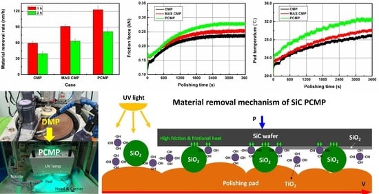
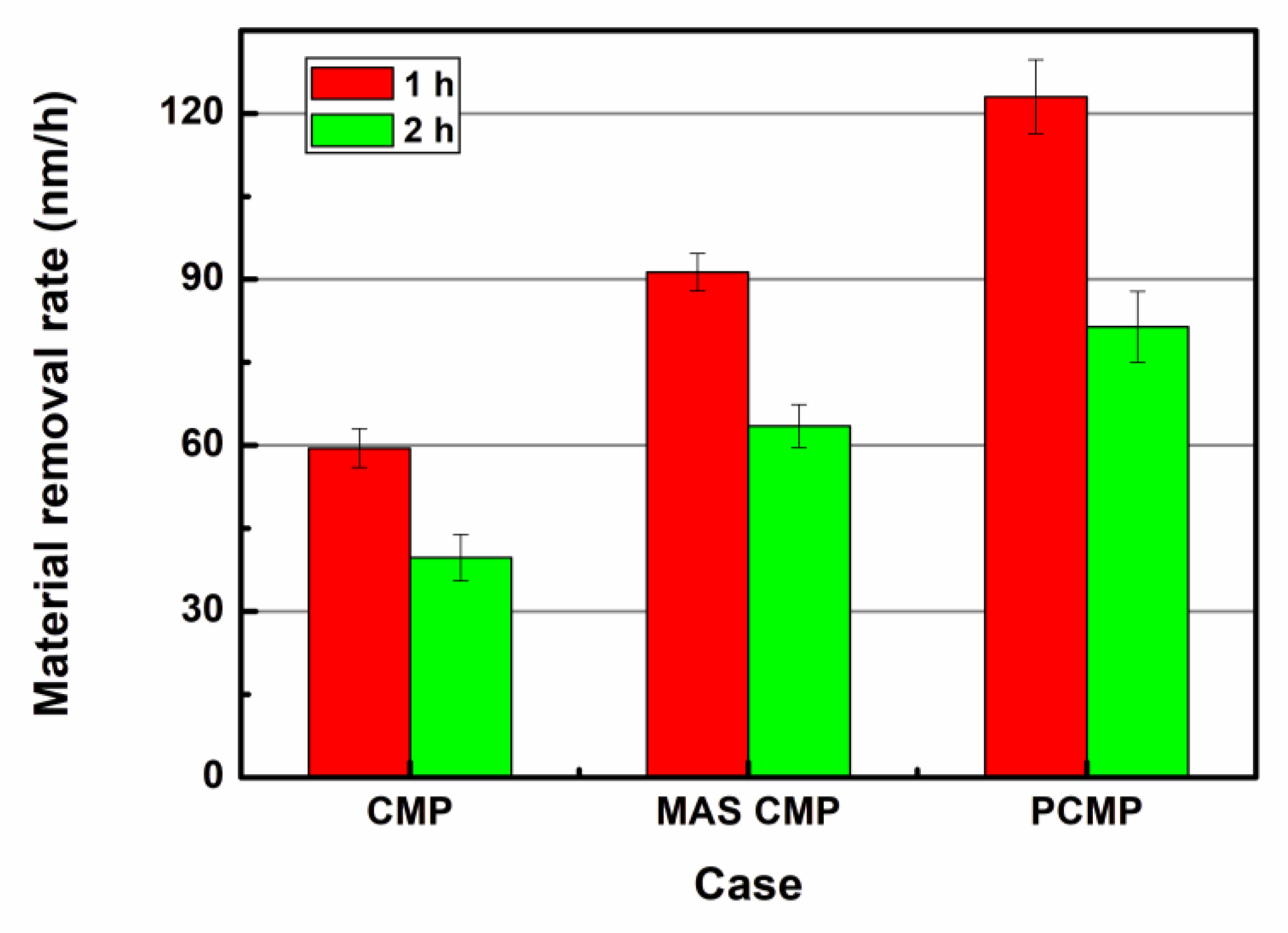
Figure 5 shows the MRRs for each experimental case. For 1 h long CMP, the MRR was 59.5 nm/h, which is extremely low owing to the high hardness and chemical stability of SiC. Although the abrasive concentration of the slurry used in this experiment was higher at 32 wt% than in typical CMP, it did not exhibit sufficient material removal efficiency. After CMP for 2 h, the MRR was 39.7 nm/h, which was lower than the CMP for 1 h. The decrease in MRR with an increase in the processing time may be due to the removal of the rough SiC surface after DMP by CMP, thereby lowering the surface roughness and removing the subsurface damaged layer.
The MAS CMP exhibited MRRs of 91.3 nm/h and 63.5 nm/h after 1 h and 2 h of processing, respectively, and showed higher MRRs than general CMP. During MAS CMP, the weight concentration of the total particles was the same as that of general CMP; however, 31.8 wt% of colloidal silica particles and 0.2 wt% of TiO2 particles were included in the slurry. Because the TiO2 particles used in the experiment are smaller than the colloidal silica particles, the total number of particles in the slurry was greater than that of the case where only 23 wt% of colloidal silica was used. In MAS CMP, the increase in MRR may be due to the increase in the total number of particles after adding the TiO2 particles and the addition of H2O2 in the slurry.
In PCMP, the UV light was irradiated to the slurry used in MAS CMP, and the MRR was higher than that of general CMP and MAS CMP. In PCMP, the MRRs for 1 h and 2 h were 123.0 nm/h and 81.4 nm/h, respectively. According to the experimental results shown in
Figure 5, the high MRR in PCMP may be due to the improvement of mechanical material removal and chemical reaction by the addition of TiO
2 particles and photocatalytic oxidation by UV light irradiation.
From the results of the 1 h processing shown in
Figure 5, the increase in MRR through MAS CMP with TiO
2 particles was 31.8 nm/h (approximately 53.5% increase over general CMP), and the MRR of MAS CMP was increased by 31.7 nm/h through PCMP (approximately 34.7% increase over MAS CMP). In the case of 2 h processing, the MRR of MAS CMP increased by 23.8 nm/h (59.9%) compared to general CMP, and in the case of PCMP, the MRR increased by 17.9 nm/h (28.2%) compared to MAS CMP.
3.2. Surface Roughness
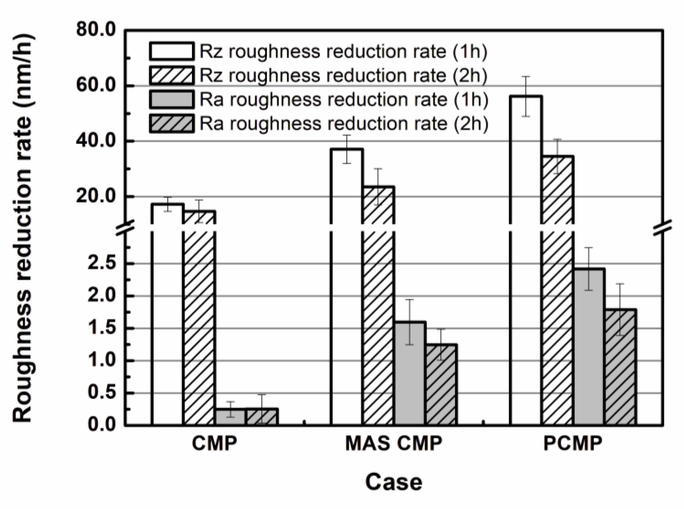
Figure 6 shows the surface roughness reduction rate after 1 h and 2 h of CMP processing. The average surface roughness of SiC wafers before CMP was Rz 92.903 μm and Ra 6.132 μm, as stated in the experimental conditions. After 1 h of CMP processing, the surface roughness values of the SiC wafer were Rz 75.756 μm and Ra 5.722 μm, and the surface roughness reduction rates were Rz 17.250 μm/h and Ra 0.248 μm/h. In the case of MAS CMP, the surface roughness values after 1 h processing were Rz 49.354 μm and Ra 4.354 μm, and the surface roughness reduction rates were Rz 37.092 μm/h and Ra 1.594 μm/h. After 1 h of PCMP, the surface roughness values were Rz 39.584 μm and Ra 3.848 μm, and the surface roughness reduction rates were Rz 56.18 μm/h and Ra 2.416 μm.
After 2 h of general CMP, the surface roughness decreased to Rz 63.562 μm and Ra 5.463 μm. After 2 h of MAS CMP, the SiC surface roughness values were Rz 39.316 μm and Ra 3.456 μm, and in the case of PCMP, they were Rz 26.738 μm and Ra 2.687 μm. In the 2 h experiment, the Rz roughness reduction rates of CMP, MAS CMP, and PCMP were 14.722 μm/h, 23.565 μm/h, and 34.513 μm/h, respectively. In addition, the Ra roughness reduction rates of CMP, MAS CMP, and PCMP were 0.253 μm/h, 1.246 μm/h, and 1.788 μm/h, respectively. Therefore, the surface roughness reduction rate tends to decrease as the processing time increases, which may be due to the fine roughness present on the SiC surface and the decrease of the surface damaged layer.
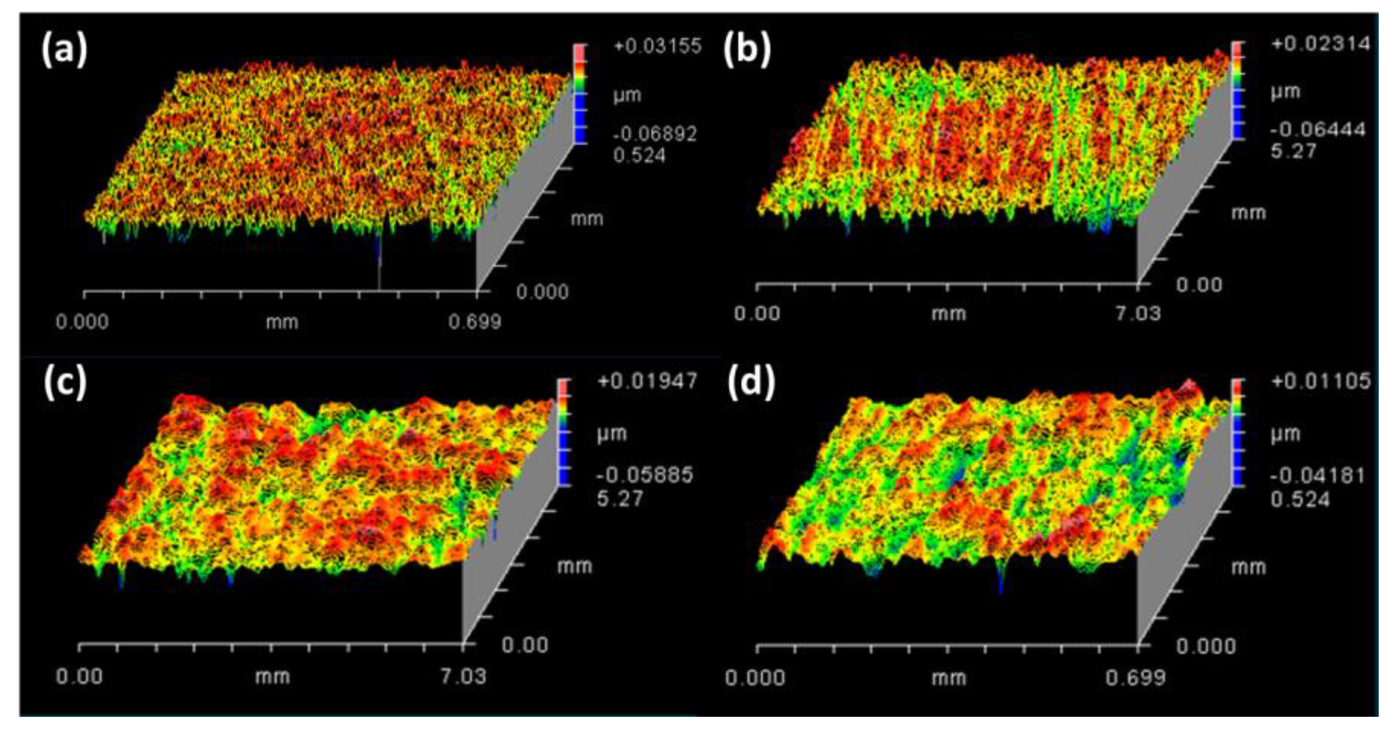
Figure 7a shows a SiC surface after DMP, and
Figure 7b–d show SiC surfaces after 2 h of processing using CMP, MAS CMP, and PCMP methods, respectively. In the case of PCMP, it is shown that the roughness present on the SiC surface after DMP is more effectively removed by the high MRR via the photocatalytic oxidation reaction.
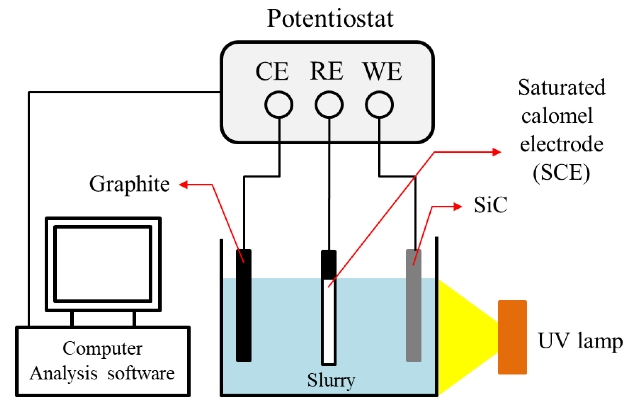
3.3. Electrochemical Analysis
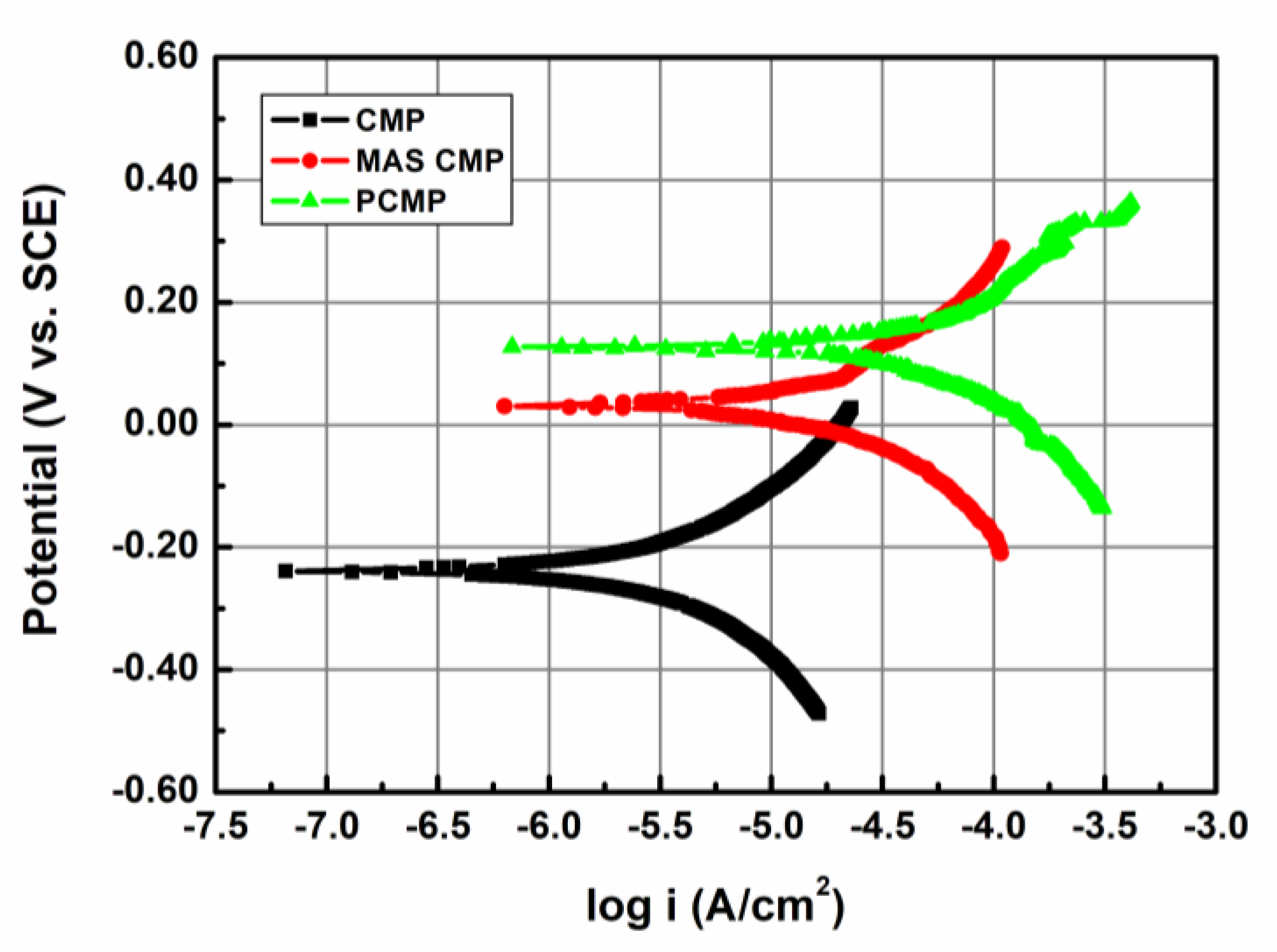
In this study, Tafel analysis was conducted using a potentiostat to understand the electrochemical reaction characteristics between SiC and slurry.
Figure 8 shows the Tafel plot in CMP, MAS CMP, and PCMP. When a general CMP slurry was used, the corrosion potential (
Ecorr) was −238.0 mV (SCE), and the corrosion current density (
icorr) was 0.54 μA/cm
2. In the case of the MAS CMP slurry,
Ecorr was 31.8 mV (SCE), and
icorr was 3.34 μA/cm
2. In the case of PCMP under UV light,
Ecorr and
icorr increased compared to MAS CMP and general CMP to 128.0 mV (SCE) and 6.88 μA/cm
2, respectively.
Because the CMP process has a material removal mechanism that removes the chemical reaction layer produced through the chemical reaction between the slurry and the material, MRR in CMP is related to the corrosion rate (CR). According to Faraday’s law, CR has a linear relationship with
icorr. The following formula is the calculation formula of CR if the unit is mpy (mils/year) [
18,
19]:
where
EW and
ρ indicate equivalent weight and density, respectively.
In the Tafel analysis for CMP, MAS CMP, and PCMP conducted in this study, the CRs were 0.43545 mpy, 2.68801 mpy, and 5.53791 mpy, respectively. In the case of MAS CMP, in which TiO2 particles and H2O2 are added to the colloidal CMP slurry, the CR increased potentially due to the oxidation of the SiC surface by H2O2, which is an oxidizer. PCMP exhibited a significant increase in the CR due to the activation of chemical reactions by ·OH radicals caused by photocatalytic oxidation by TiO2 catalysts and UV light.
3.4. Friction Force and Temperature
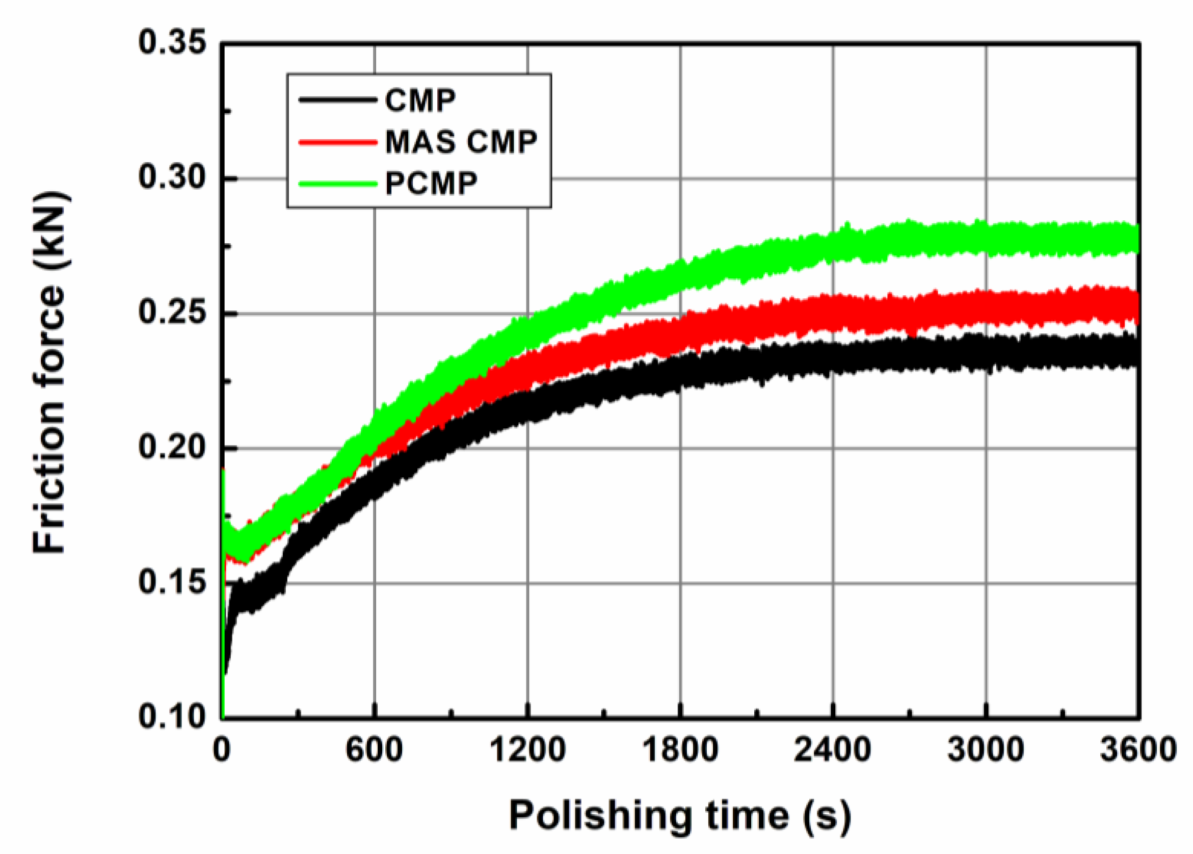
CMP is a process in which interfacial friction by particles placed between wafers and polishing pads affects the MRR. Various factors affect the friction force in CMP, such as the material of the wafer, the characteristics of the polishing pad, the type of abrasive particles, and the pressure and speed during processing. In addition, the friction force of the CMP is also affected by the chemical reaction between the slurry and the wafer.
In this study, changes in frictional force and temperature in CMP, MAS CMP, and PCMP were observed, as shown in
Figure 9. The friction force in a PCMP is higher than that in a general CMP and MAS CMP, and the MAS CMP showed a higher friction force than that in a general CMP. The friction forces at CMP, MAS CMP, and PCMP were 0.215 kN, 0.231 kN, and 0.248 kN, respectively. The friction forces shown in
Figure 9 increase during the CMP and then gradually converge at the maximum friction force. The maximum frictional forces at CMP, MAS CMP, and PCMP were 0.243 kN, 0.260 kN, and 0.274 kN, respectively. The increase in friction in MAS CMP may be due to the oxidation of the SiC surface following the addition of H
2O
2 and the improvement of mechanical material removal by TiO
2 particles. The high friction force in PCMP seems to be the effect of the activation of chemical reactions by photocatalytic oxidation. In addition, in PCMP, it seems that high friction and MRR can more effectively planarize the rough SiC surface produced by DMP.
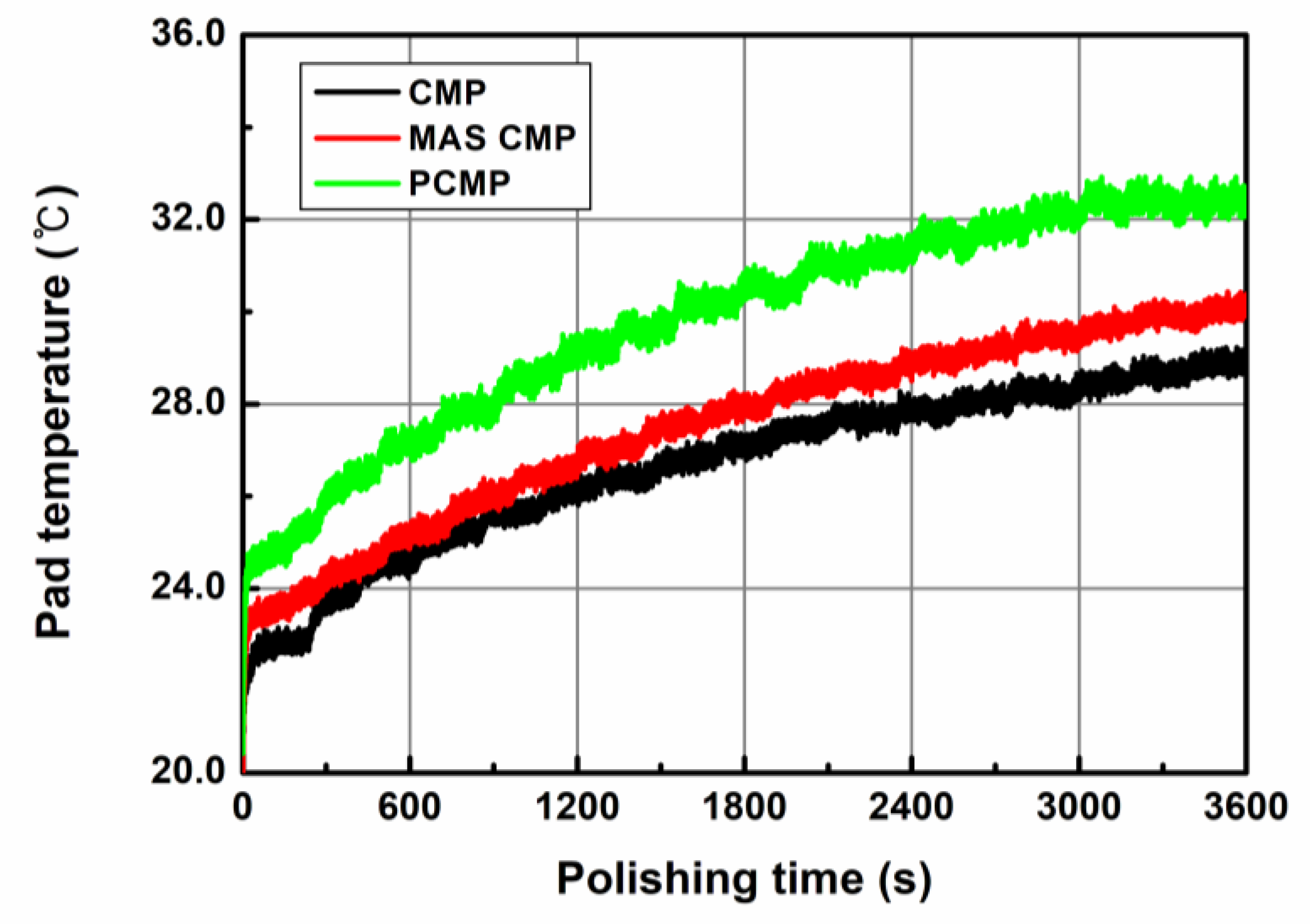
Figure 10 shows the temperature changes during CMP, MAS CMP, and PCMP. The pad temperature before the start of the experiments was maintained at 19.5 °C. As shown in
Figure 10, the temperature of the polishing pad was the highest in PCMP under UV light, and the general CMP showed the lowest temperature. The average temperatures of CMP, MAS CMP, and PCMP were 26.4 °C, 27.5 °C, and 29.7 °C, respectively. The temperature increases at CMP, MAS CMP, and PCMP were 9.40 °C, 10.41 °C, and 11.80 °C, respectively. The temperature in CMP is closely dependent on friction, and because this research conducted an experiment under the same pressure and rotation speed, it may be dependent on the material removal rate according to the CMP method. In addition, the high pad temperature during CMP is expected to help improve MRR by helping the chemical reaction between slurry and SiC wafers.
3.5. Material Removal Mechanism of SiC PCMP
In previous studies [
14,
20], the material removal mechanism of SiC PCMP is explained by the activation of chemical action by photocatalytic oxidation.
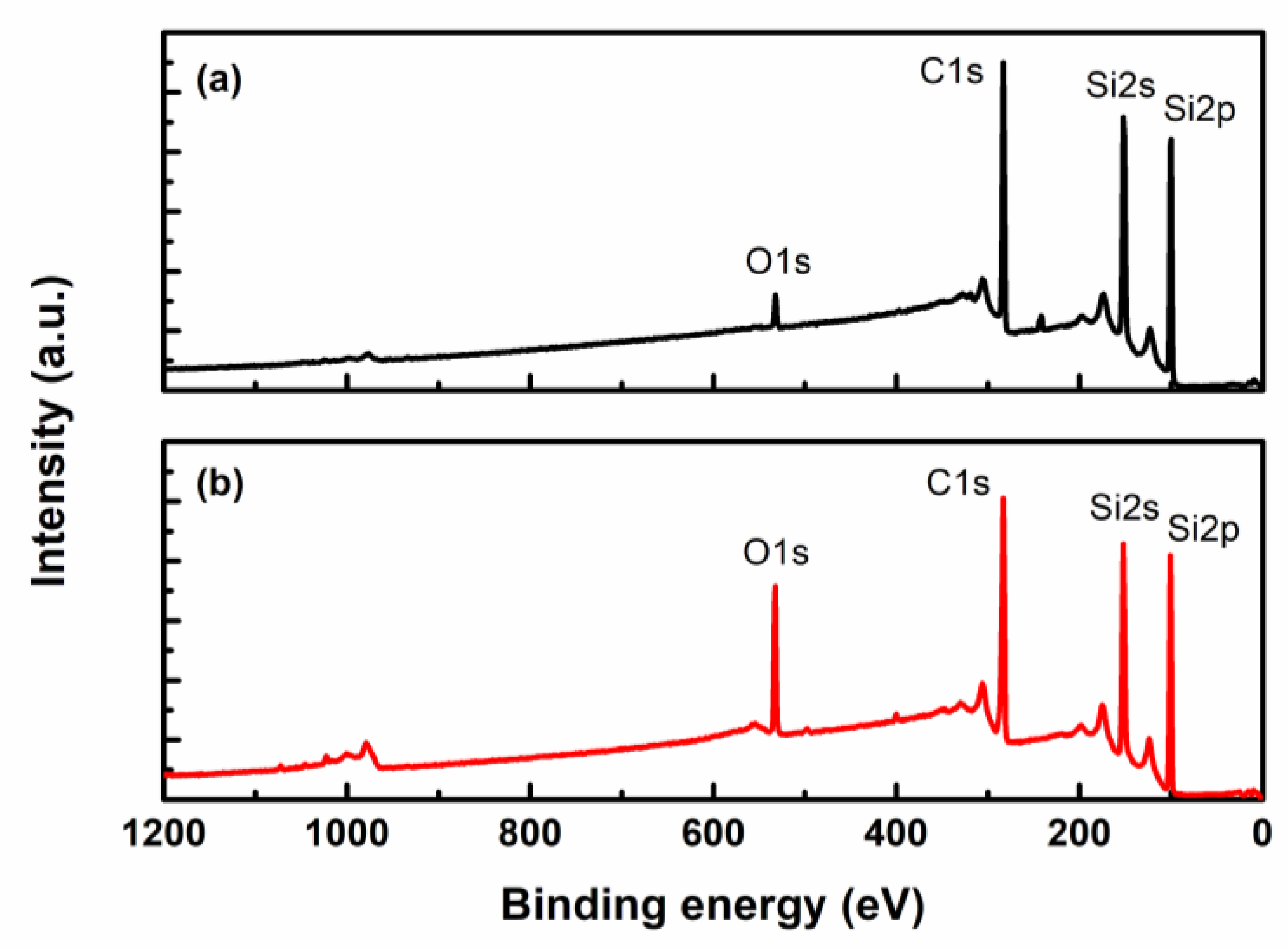
Figure 11a shows the XPS measurement result of the as-received SiC wafer, and
Figure 11b shows the XPS measurement result of the SiC wafer immersed in slurry for five days and irradiated under UV light. The increase in the O1s peak in
Figure 11b from the XPS measurement results shows that the SiC surface can be oxidized during PCMP. The Tafel analysis results in
Figure 8 also confirm that CR increases by photocatalytic oxidation during PCMP, and thus O1s peak can increase, as illustrated in
Figure 11. In
Figure 11, in the case of the PCMP condition, the C1s peak is shown to be decreased, and this seems to be a result of the photocatalytic oxidation of SiC and ·OH in Equation (1).
The surface of the oxidized SiC is removed by particles in the slurry, and the TiO
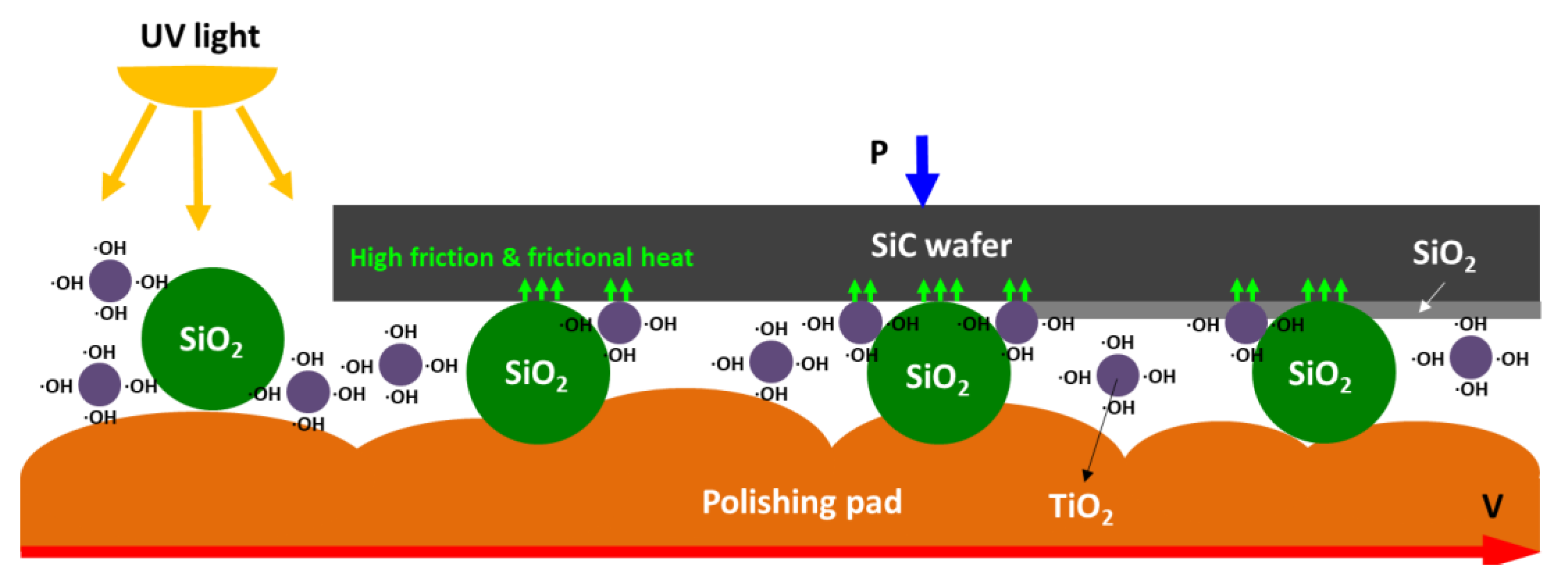
2 used as a photocatalyst also contributes to the material removal. In addition, the high frictional force and frictional heat generated during SiC PCMP may have resulted in a higher material removal efficiency than the general CMP that uses only colloidal silica particles. In addition, PCMP appears to rapidly reduce SiC surface roughness due to high friction, temperature, and MRR. Therefore, the high MRR of SiC PCMP may be the result of synergy with the tribology in CMP and photocatalytic oxidation, as shown in
Figure 12.
4. Conclusions
In this study, the techniques of SiC PCMP, MAS CMP containing colloidal silica particles (72 nm), TiO2 particles (25.4 nm), and H2O2, and CMP using only colloidal silica were compared from a tribology perspective. When H2O2 and TiO2 particles were added to the colloidal silica slurry, the MRR in SiC CMP increased, which may have been caused by the oxidation reaction of the slurry and SiC and the increase in the number of abrasive particles. In addition, higher friction force and temperature were measured in MAS CMP than in general CMP. Among the three CMP methods, the highest MRR, frictional force, and temperature were identified in PCMP under UV light and with TiO2 particles (photocatalyst), which may have been due to photocatalytic oxidation. According to the Tafel analysis, the highest icorr and CR were measured in PCMP, and the XPS analysis of the SiC surface confirmed that an oxide film that is relatively easier to remove mechanically than SiC was formed. Therefore, the material removal mechanism in PCMP could have involved mechanically removing the surface oxide layer formed by activating the photocatalytic oxidation reaction under UV light, photocatalysts, and the chemical reactions caused by the temperature rise.


