Article

Efficient Sub-Modeling for Adhesive Wear in Elastic–Plastic Spherical Contacts

Department of Mechanical Engineering, Technion, Haifa 32000, Israel
*
Author to whom correspondence should be addressed.
Lubricants 2023, 11(5), 228; https://doi.org/10.3390/lubricants11050228
Submission received: 29 April 2023 / Revised: 15 May 2023 / Accepted: 16 May 2023 / Published: 18 May 2023
(This article belongs to the Special Issue Advances in Contact Mechanics)

Abstract

:
This paper presents a novel approach for simulating adhesive wear in elastic–plastic spherical contacts using an improved finite element sub-model. Initially, a global model with a coarse mesh identifies the potential wear region under combined normal loading and tangential displacement. Subsequently, a refined mesh sub-model simulates the crack initiation and propagation until the formation of a wear particle. This refined sub-model efficiently handles a wide range of spherical radii and normal loads. An expression is derived relating the dimensionless wear volume and wear rate to the dimensionless normal load, revealing the limited effect of the sphere radius on the wear rate. The effect of the mechanical properties on the wear particle morphology is also analyzed.

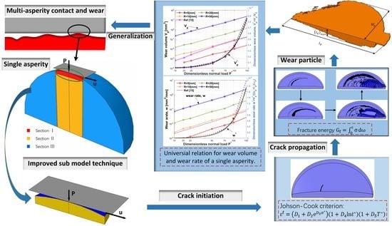
Graphical Abstract

1. Introduction

Wear is the key factor causing material loss and mechanical failure between contacting surfaces, which typically occurs in various tribo-components. There are mainly five types of wear in tribology: abrasive, erosive, corrosive, fatigue and adhesive [1]. Among them, adhesive wear is the least avoidable between contacting surfaces that are subjected to strong adhesive bonds, in which the material removal occurs at the contacting asperities of the mating surfaces [2]. Although very common, an accurate prediction of adhesive wear is still a challenging question in tribology [3]. Hence, developing an effective model to reveal the mechanism of adhesive wear is of great significance.
Archard [4] replaced Holm’s concept [5] for the removal of atoms with the removal of spherical wear particles of the same radius as their contact area to describe the adhesive wear process. This alternative approach was supported by experimental evidence [6], showing that the material removal is not at an atomic level.
Archard [4] proposed a model for the adhesive wear, based on a linear relation to calculate the wear volume, which was expressed as W = K P L / H where W is the wear volume, P is the normal load, L is the sliding distance, H is the hardness and K is the wear coefficient.
Due to the simplicity and practicality of Archard’s model in engineering applications, it became a well-accepted wear model in the following decades [7]. However, it has inherent limitations, one of which is the lack of a physical understanding of the mechanism of the wear particle formation. Therefore, Archard’s model can only give a reliable prediction for cases where the wear coefficient K was already found experimentally, implying that several wear experiments imitating the correct tribological system are required to obtain wear predictions.
Indeed, a lot of work has been done to perform the integrated analysis of the fracture behavior to enable adhesive wear modeling [7]. The pioneering study performed by Hills and Ashelby [8] introduced the classical fracture mechanics to explore the wear behavior between contacting surfaces. In Ref. [8], the crack was initially generated in a pre-selected location. Subsequently, Suh and coworkers [9,10] developed the delamination theory of wear, in which they assumed the crack nucleation and subsurface crack propagation. Here also, the crack location was predetermined. Although the wear particle formation process can be investigated by a predetermined initial crack location, it limits the crack to propagate from this predetermined location, which may cause an unreliable prediction. Hence, for proper wear modeling, a model that can simulate the crack initiation is required.
The finite element method (FEM) is an efficient method to determine the crack initiation based on the damage mechanism concept. By introducing the Johnson–Cook strain-based ductile fracture criterion [11], Wu and Shi [12] were able to simulate a 2D crack initiation and propagation using a finite element model for a cylindrical contact. According to [12], the crack initiation was at the contact surface, which is in contradiction to the assumption made in the previously mentioned studies [8,9,10].
To simulate the adhesive wear of 3D spherical contacts an FE model, Zhang and Etsion [13] used the JC criterion, similar to [12], for the crack initiation. However, a different approach was used for the crack propagation in [13]. Specifically, a fracture energy criterion [14] was used, where the fracture energy, G f , described the energy needed to open a unit area of the crack [14]. By incorporating this physical approach into the adhesive wear simulation, the crack propagation was modeled as a crack opening process rather than the same way as its generation.
In Ref. [13], the static friction and the adhesive wear of a spherical contact under combined normal and tangential loading were presented for both elastic and elastic–plastic regimes for the normal loading of a sphere with a 10 mm radius. In Zhang’s study [13], an extremely refined mesh was required to obtain an accurate wear prediction, which was very time consuming, limiting the study to one material and two normal loads. However, some insights regarding the formation of the adhesive wear particle were obtained in both [12,13]. The research showed that the crack initiation started at the trailing edge of the contact surface and then, another crack was initiated at the leading edge. As the tangential displacement increased, the cracks propagated and eventually connected with each other, resulting in the formation of a wear particle. It can be inferred that investigating the adhesive wear using predetermined cracks may not provide accurate results.
In order to improve the computing efficiency of the FE wear model [13], Zhang and Etsion [15] adopted a sub-model technique which enabled them to efficiently calculate the wear volume and wear rate for different normal preloads. While this sub-model was appropriate to characterize the wear particle morphology, the model was not able to present the realistic mechanical response during the wear process, which is required to better analyze the mechanism of the wear particle formation, tangential stiffness and friction behavior.
In the present study, an improved sub-model technique is suggested which innates the advantages of both the models previously proposed by Zhang and Etsion [13,15]. Thus, the present improved sub-model is able to efficiently predict the mechanical response in a spherical contact and the wear particle morphology for different radii, normal preloads and material properties.

2. Theoretical Background

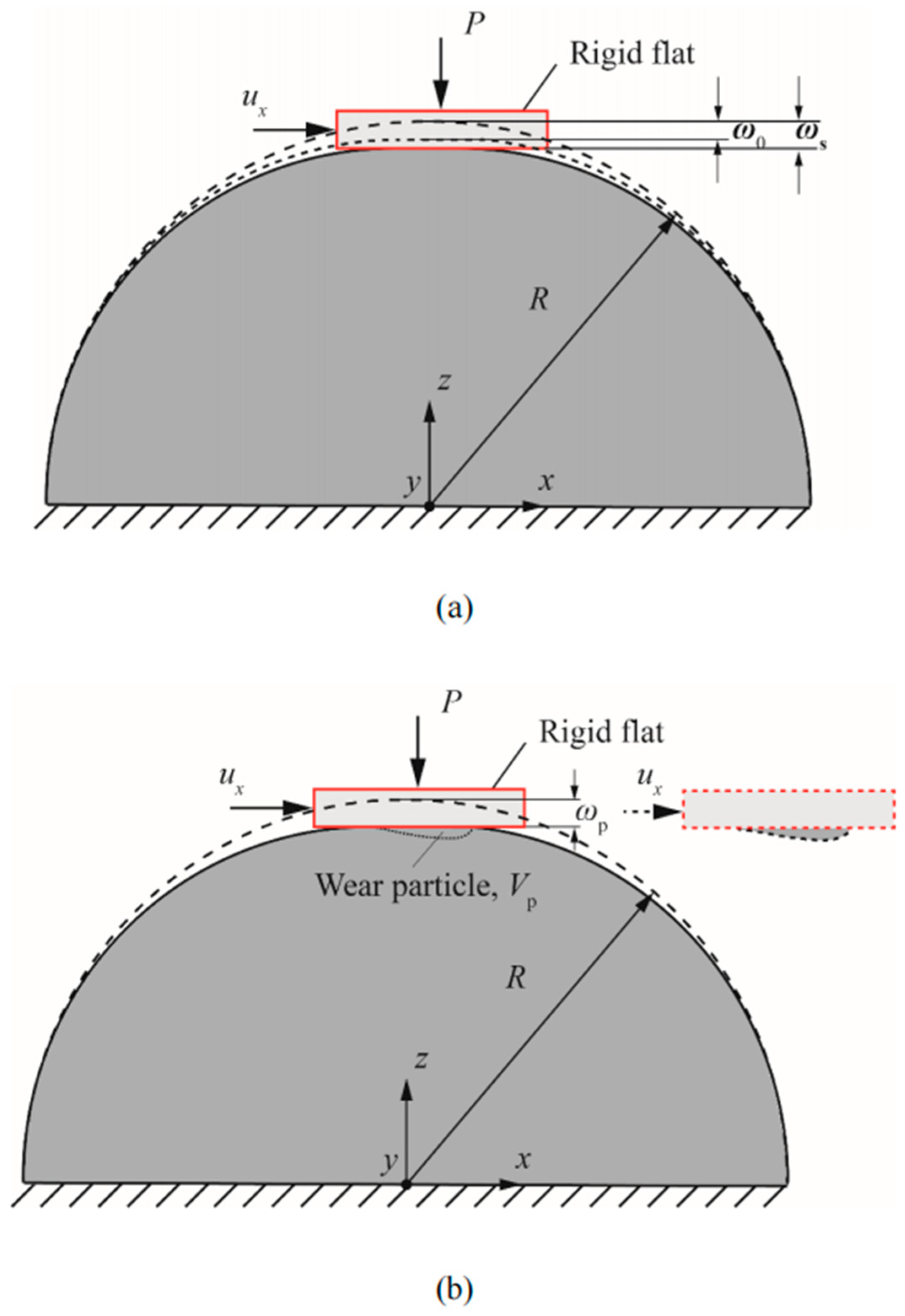
Figure 1, taken from [13], presents a schematic representation of the contact problem of a rigid flat and a homogeneous deformable sphere under combined normal and tangential loading. The contact condition between the rigid flat and the outer surface of the sphere is a full stick. The loading process consists of two stages. At the beginning of the simulation, a normal load P is applied to the rigid flat, resulting in a vertical displacement of the rigid flat, also termed as the interference and denoted by ω 0 . Due to the deformation of the sphere tip, a circular contact area A of diameter d 0 is obtained. The characteristics of the contact area, friction coefficient and corresponding critical load, L c , were studied previously by Brizmer et al. [16,17]. The normal load is usually normalized by the critical normal load at the yield inception under the full stick contact condition, P * = P / L c , given in Ref. [16].
L c = L c π 3 Y 6 C ν 3 R 1 ν 2 Y E 2
where L c = 8.88 ν 10.13 ν 2 + 0.089 and C v = 1.234 + 1.256 ν , and R , E , Y and ν are the radius of the sphere, Young’s modulus, the yield strength and Poisson’s ratio, respectively. With this normalization, the contact is elastic–plastic for P * > 1 . For P * < 1 , the contact is elastic.
Following the normal preload, a tangential displacement u x is applied to the rigid flat until a formation of the wear particle is achieved.
Similar to Ref. [13], the adhesive wear propagation is studied using the FEM. To model the fracture process, two fracture criteria are used. First, the Johnson–Cook (JC) criterion [11] is used for the damage initiation of the first crack. According to the JC criterion, the crack occurs when the strain at a material point reaches the equivalent plastic strain ε f defined in [11] as the following equation.
ε f = D 1 + D 2 e D 3 σ * 1 + D 4 l n ε ˙ * 1 + D 5 T *
As shown in Equation (2), the plastic strain consists of three parts, which describes the effect of the stress, the strain rate and the temperature, respectively. For a quasi-static and isothermal analysis, the effects of the strain rate and temperature are absent ( D 4 = D 5 = 0 ) . Hence, Equation (2) can be reduced to the following.
ε f = D 1 + D 2 e D 3 σ *
The equivalent plastic strain ε f in Equation (3) depends on the stress triaxiality σ * , which is given in the following form.
σ * = σ m / σ ¯
where σ m is the hydrostatic stress and σ ¯ is the von Mises equivalent stress.
Equation (3) and first bracket of Equation (2) follow the form presented by Hancock and Mackenzie [18]. The coefficient D 1 is the crack nucleation strain for the materials that allow for a considerable plastic flow prior to the crack nucleation. D 1 will be zero otherwise. D 2 is a material constant and D 3 expresses how the equivalent plastic strain is affected by the stress triaxiality σ * . These three parameters can be obtained from the tensile tests [19,20].
The fracture energy G f [14] for the damage evolution is used to enable the crack propagation. The opening of a crack requires the expenditure of energy to overcome the associated stress. Therefore, the crack opening process leads to the absorption of energy. The amount of energy needed per unit of the crack area in opening the crack from zero to a given width c is calculated using the following equation [14].
G f = 0 c σ d ω
With this approach, the softening response after the damage initiation, which is characterized by the reduction in the associated stress needed to open a crack as the crack length increases, is expressed by a stress-displacement response rather than by a stress–strain response. In the FEM, this stress-displacement concept requires a definition of a characteristic width c and the characteristic width has size effect on the fracture energy. The fracture energy given by Hu and Wittmann [21] from the tensile tests is a function of the dimensionless crack size, normalized by the specimen width, which shows that the measured fracture energy is significantly influenced by the dimensionless crack size. In order to eliminate the crack size effect, size-independent fracture energy should be used. In a further study the relation for the size-independent fracture energy was given as the following equation [22].
G F = K I C 2 E
where K I C is the size-independent specific fracture energy. This equation enables the extraction of fracture energy without experiments and is free of the crack size effect.
In this study, the ABAQUS/explicit 2020 platform was used to predict the adhesive wear behavior. In the given wear modeling problem, this fracture energy is associated with the length of the mesh size in ABAQUS [23] since, in order to open a crack, the crack needs to go through an entire element at the crack tip. The sensitivity of the mesh was evaluated in [15] to determine the impact of the mesh size on the wear volume. It was shown in [15] that below a certain mesh size, a further reduction had a minor effect on the results but significantly increased the computation time.
Using the sub-model technique presented in [15], the boundary conditions of all the surfaces can be obtained from the deformation distribution of the global model. This means that all the surfaces are pre-deformed in the same way as they are in the global model. However, the rigid flat is not included in this sub-model, meaning that the normal load and tangential displacement cannot be calculated. Hence, it is impossible to capture the frictional behavior at the contacting surface. Moreover, although the less efficient global model presented in Ref. [13] was able to capture the friction behavior, as the predefined normal load decreases, a much smaller mesh size is needed, which requires a longer computation time. Therefore, a more efficient sub-model that can overcome the above limitations is suggested hereafter.

3. FE Model

The solution process consisted of two steps. First, a simulation using the global model without element deletion was performed to derive the size and deformation distributions for the sub-model, which is similar to the process described in [15]. In the second step, an improved sub-model was used with the obtained deformation distribution and element deletion to simulate the wear and friction behavior.
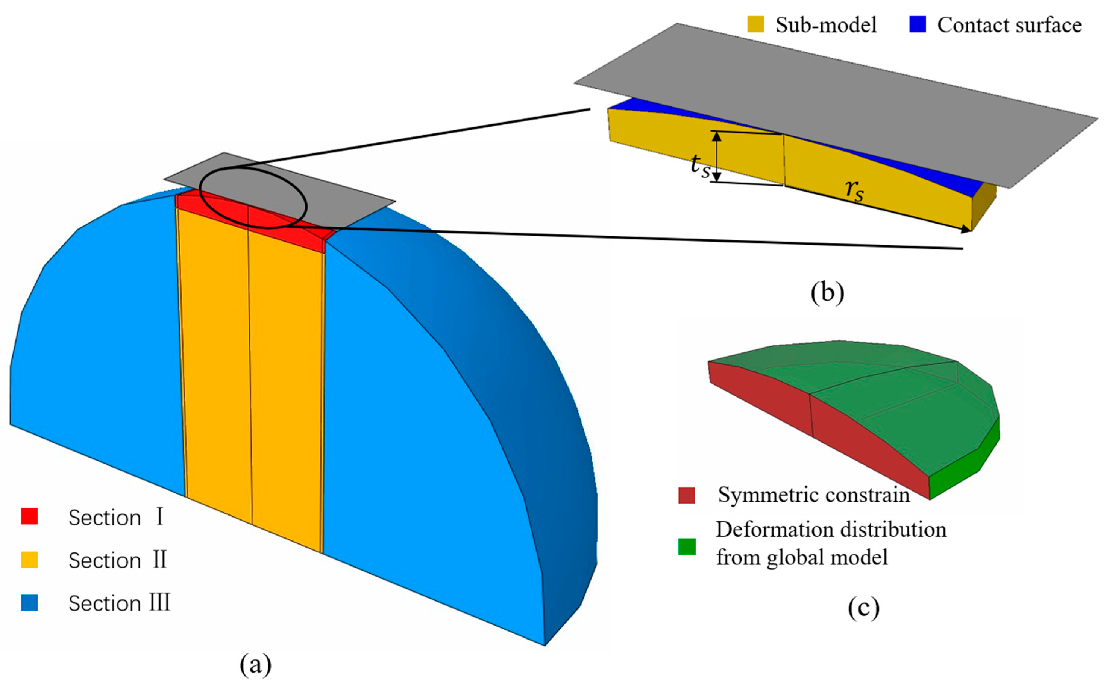
Figure 2 presents the global model with different sections consisting of different mesh densities and the location and assembly of the improved sub-model. The mesh design in the global model was the same as the one described in Ref. [13]. As shown in Figure 2a, three different sections are shown. Section I in red was where the potential wear particle was expected and had the finest mesh. Section II and III highlighted in yellow and blue, respectively, had a gradually increasing mesh size with an increasing distance from section I.
Using the sub-model technique [15], only a part of section I was used for the second solution step. This sub-model had a refined mesh compared to the mesh in the global model for better accuracy. As shown in Figure 2b, a plate-like sub-model highlighted in yellow with definitions of its thickness t s and radius r s in contact with a rigid flat is shown. The contact surface between the rigid flat and the improved sub-model is highlighted in blue.
The thickness t s and the radius r s of the improved sub-model were chosen based on the location of the maximum stress in section I of the global model. Due to the fact that the investigated material model is assumed to be perfectly elastic–plastic, these two parameters indicate the size of the obtained yield region. The thickness t s and the radius r s are defined as the vertical and tangential distances from the tip of the sphere to where the yield region is included.
These two parameters were slightly larger than those in [15], as their values were selected based on the location of the maximum strain found in the global model. Furthermore, using the geometry of the sub-model similar to [15] will result in the crack propagating beyond the sub-model boundary. This happens, since the element deletion was not included in the deformation distribution applied on all the surfaces of the sub-model in [15]. Thus, the interference in [15] was reduced and the thickness of the sub-model necessary to prevent the crack from penetrating the sub-model boundary was smaller.
Investigation on the effect of these two parameters, t s and r s , was performed by separately conducting simulations with twice the thickness and radius. Although the differences in the wear volume and static friction coefficient were less than 7%, the computational time almost doubled. This indicated that the sub-model’s size determined by the maximum stress location was sufficient to effectively capture the wear process.
Figure 2c shows the boundary conditions applied to the improved sub-model. The contact surface was left free of constraints. A symmetric constraint was imposed on the symmetrical surface, highlighted in red, while the deformation distribution from the global model was applied to the side and bottom of the surface, highlighted in green. The deformation distribution from the global model serves two purposes: primarily, to produce contact between the plate-like sub-model and the rigid flat and to eliminate the effects caused by the geometry change, as the stress field depends on the geometry and the improved sub-model is not in a spherical shape.
It should be mentioned that an alternative solution was attempted, where instead of using the deformation distribution from the global model, fixed boundary conditions were used. However, these boundary conditions resulted in a significantly different crack initiation and propagation compared to Ref. [13]. As a result of the fixed boundary condition on the bottom, the sub-model was unable to deform in the normal loading direction, which led to a 50% reduction in the interference. Although the tangential behavior was primarily dictated by the behavior of the contact surface, it was also heavily influenced by the fixed boundary condition on the side, as this condition significantly altered the stress field. Moreover, the comparison presented in the results section demonstrates that the friction behavior obtained using the improved sub-model, which incorporated the deformation distribution on both the bottom and side, closely matched the results obtained in [13] using the global model. Therefore, the deformation distribution boundary conditions are necessary for accuracy and efficiency.
Finally, a full stick contact condition was defined between the rigid flat and the sphere. After the crack initiates, one more interaction must be defined, as there is a newly formed surface due to the failed elements deletion from the mesh. Eventually, a wear particle may form between the rigid flat and the slip interface, which is the interface between the newly formed wear particle and the bulk of the sphere. The interaction property applied on the slip interface is assumed to be frictionless to simplify and simulate. Thus, a shear crack cannot transmit shear or normal tensile stresses [24].
The elements with an aspect ratio close to one were used to reduce the mesh sensitively to the crack propagating direction; representing the uniform mesh as was also shown in [15]. In the present study, the mesh independence check was performed by increasing the mesh density and guaranteeing the relative error within a small, predetermined tolerance (10%) for all the normal loads and sphere radii. For instance, using R = 10 [mm] and P * = 100, changing the mesh size from 0.01 mm to 0.005 mm resulted in a change of the results below 9%. However, the calculating time of the latter was approximately twice that of the former. Therefore, the mesh size of 0.01 mm was used for R = 10 [mm] and P * = 100.

4. Results and Discussion

The adhesive wear and friction behaviors of the spherical contact under combined loading were studied by carrying out wear simulations using the improved sub-model for the sphere radius ranging from 5 [mm] to 50 [mm], with dimensionless normal loads P * ranging from 15 to 150. It was found in the current model that the tangential displacement u x = 9 ω 0 was sufficient to achieve a wear particle for all the different simulations. It was also observed in [13] with the global model. Hence, to ensure the full formation of the wear particle, a value of u x = 12 ω 0 was used for all the simulations. Similarly, in Refs. [13,15], the sphere material was aluminum 2024 T351, as this particular material was thoroughly studied both numerically and experimentally [25,26,27,28]. The material properties of aluminum 2024 T351 are: E = 74   G p a , v = 0.33 , Y = 325   M p a and a density of ρ = 2780   K g / m 3 . The JC criterion coefficients of the damage initiation for aluminum 2024 T351 are (Ref. [28]): D 1 = 0.13 , D 2 = 0.13   a n d   D 3 = 1.5 . For the damage evolution, the fracture energy was G f = 20   K J / m 2 [28].
In the following, the verification of the improved sub-model is presented, followed by the investigation of the tangential mechanical response and the wear particle morphology for the different normal loads and sphere radii. The effect of changing the different mechanical properties ( D 1 , D 2 , D 3 , G f , E / Y ) on the obtained results is also discussed.

4.1. Verification of the Improved Sub-Model

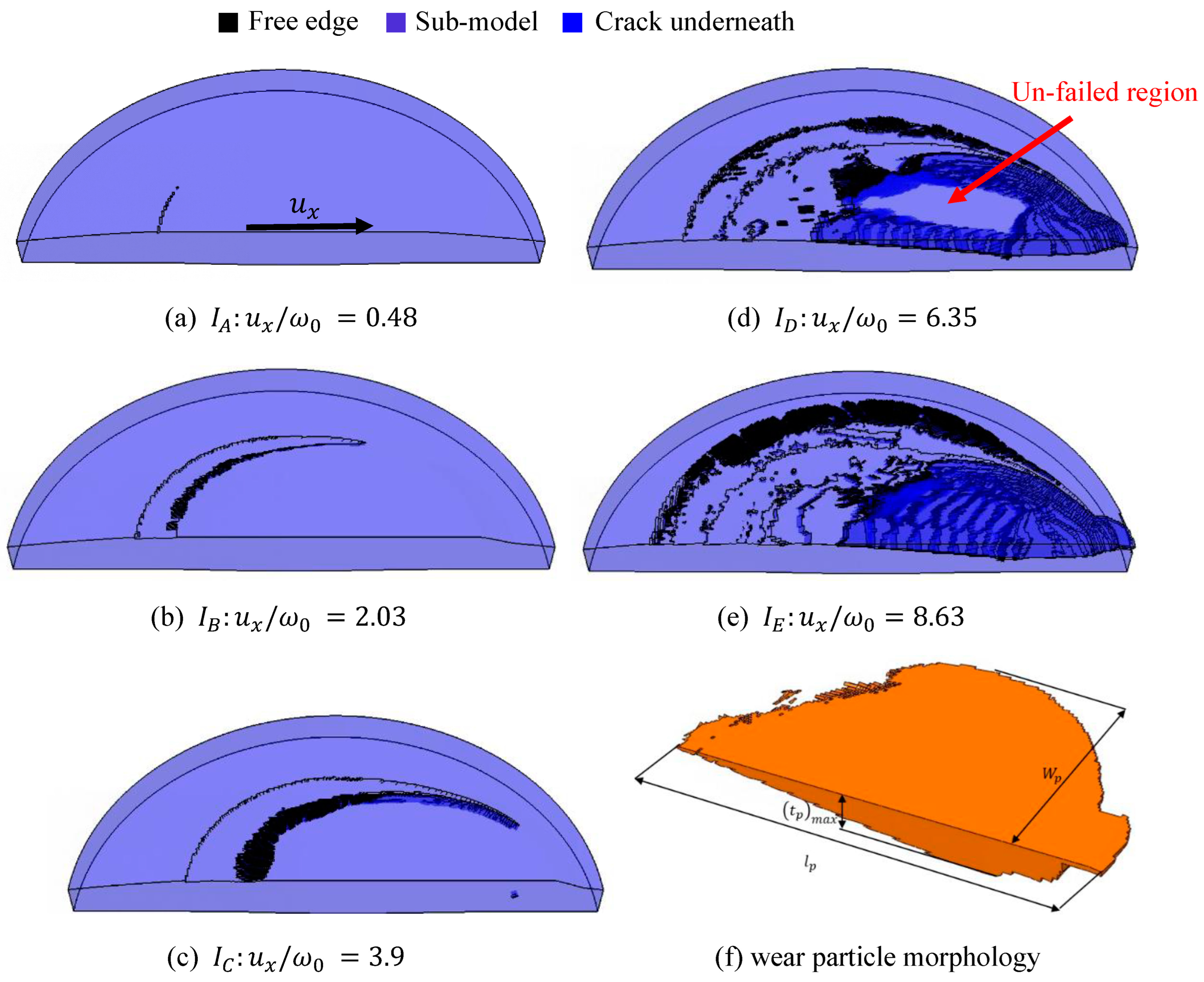
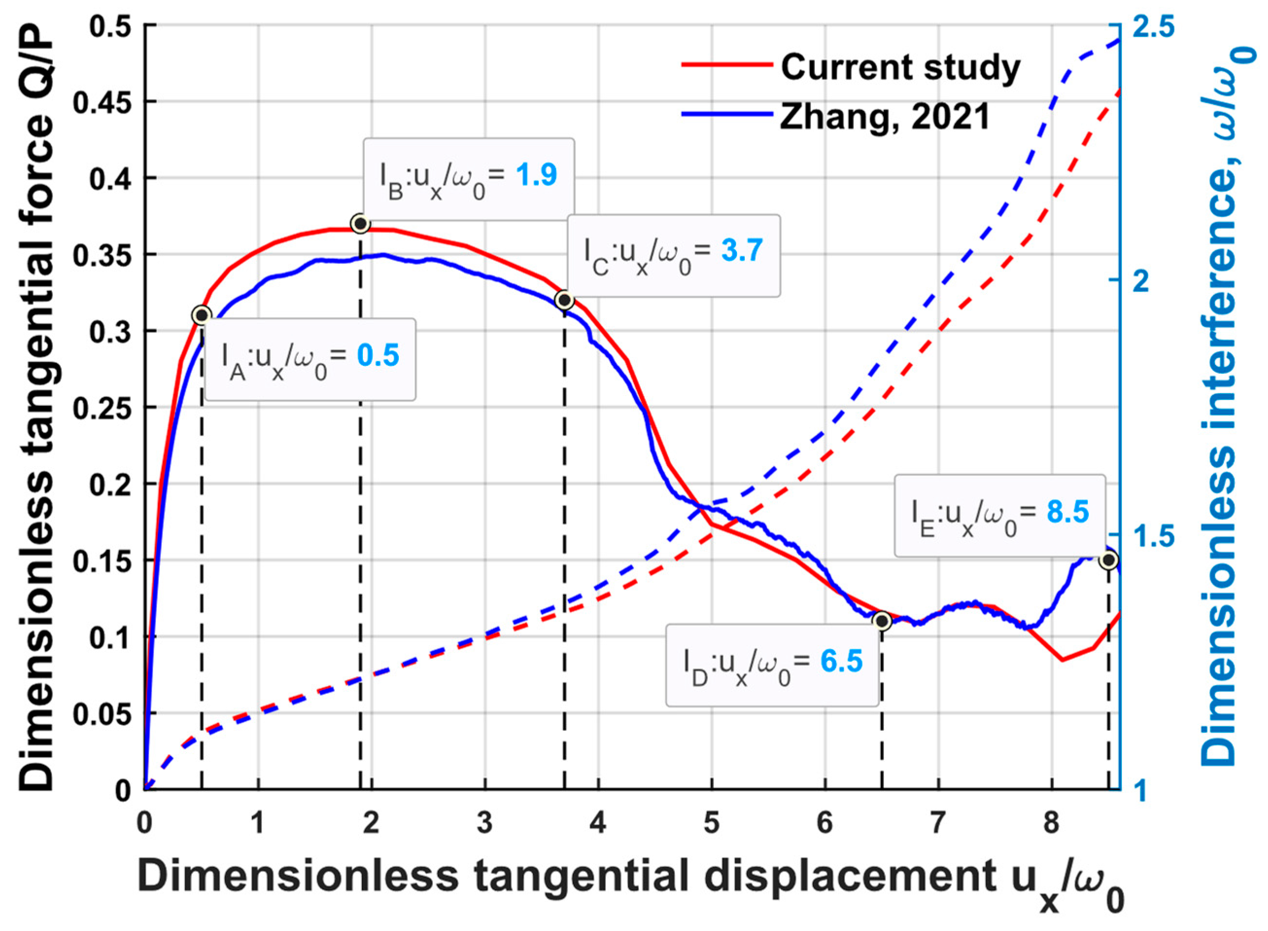
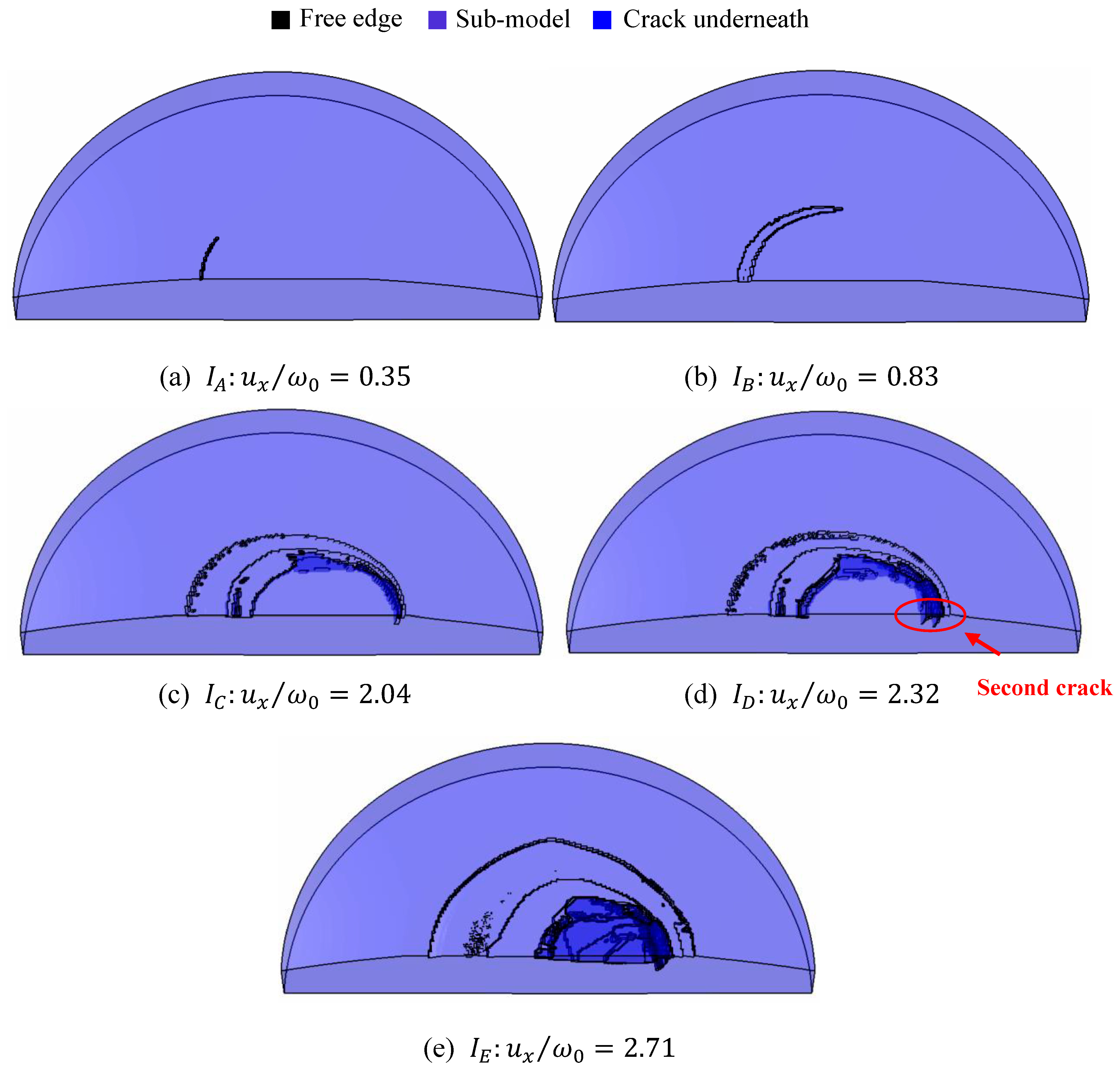
The results from Ref. [13] were used to verify the adequacy of the present model. Figure 3 shows the five instants for the fracture evolution obtained by the improved sub-model, corresponding to the five instants obtained in Ref. [13] for the R = 10   [ m m ] and P * = 100 case with the definition of the wear particle parameters. The black color represents the free edge formed during the fracture evolution process; the deeper blue color represents the crack formed below the contact surface. Figure 4 shows the friction behavior and the interference for the same case, as shown in Figure 3. Both the dimensionless tangential force Q / P and the dimensionless interference ω / ω 0 are plotted with respect to the dimensionless tangential displacement u x / ω 0 . The five instants of the fracture evolution are marked in vertical dash line.
For instant I A , the crack initially appeared on the trailing edge of the contact surface. The term ‘trailing edge’ refers to the edge located in the direction opposite to the tangential displacement u x , as indicated by the arrow shown in Figure 3a pointing in the u x direction. With an increasing tangential displacement, the crack spread along the edge of the growing contact interface, and at instant I B , the tangential force reached its maximum, resulting in a sliding inception. At instant I C , the first crack at the leading edge under the contact surface appeared. With the fracture extending below the contact surface, the fracture from the trailing edge linked with the one from the leading edge at instant I D , as shown in Figure 3d. A region of un-failed elements that were not deleted according to the JC and fracture energy criteria was surrounded by the linked cracks. Eventually, at instant I E the un-failed region vanished leading to the wear particle creation. These five stages for the fracture evolution using the improved sub-model matched well with the results given in [13]. The differences in the corresponding tangential displacement for the five instants, as shown in Figure 4, were 4%, 6.8%, 5.4%, 2.3% and 1.5%, respectively.
Along with the crack initiation and propagation, the tangential force behavior of the improved sub-model corresponded well to the results from [13]. The tangential stiffness reduced with the increasing tangential displacement u x until instant I B , at which the tangential stiffness completely vanished. The static friction coefficient represented by Q m a x / P was 0.36 for the improved sub-model and 0.35 in [13]. The relative error of the static friction coefficient between these two models was less than 5%.
Regarding the comparison between the dimensionless interference shown in Figure 4, the difference between [13] and the current result increased with the dimensionless displacement, which was due to the element deletion, as the element size used in the improved sub-model was larger than in [13]. However, the largest difference was less than 7%.
The wear particles formed in [13] and the one formed using the improved sub-model were similar in shape, having the shape shown in Figure 3f. The maximum thickness and length of the wear particle in [13] were t p m a x = 0.012 R and l p = 0.16 R , with a particle volume of V p = 4.3 e 2   [ m m 3 ] . The corresponding value using the improved sub-model were t p m a x = 0.0133 R , l P = 0.155 R and V p = 4.36 e 2   [ m m 3 ] . The differences between these three parameters were less than 10%, especially for the wear particle volume having a 2% difference. An additional parameter was also denoted in Figure 3f, which was the wear particle half width W p , being W p = 0.063 R for this case.
To conclude, the results predicted by the improved sub-model were in a good agreement with the predictions made in [13], validating the improved sub-model for predicting the tangential behavior wear particle geometry. These results verified that the new sub-model can provide a reliable prediction for the wear morphology and the mechanical response, thereby validating the effectiveness of the present model.
The computation time was reduced from 90 h to 30 h, compared to the model used in [13]. A further reduction in the computation time can be achieved by reasonably increasing the loading rate of the simulation, both in the normal and tangential directions. Moreover, as shown in Figure 3, it can be observed that some non-contact and non-wear regions existed, which had no effect on the wear predictions when the tangential loading was terminated, indicating that the current sub-model simulating area can be further reduced for the purpose of a parametric study. Therefore, using a smaller sub-model simulating region compared to the present one, which fully covers the potential wear and contact regions and reasonably increases the loading rate, can further reduce the simulating time. For R = 10 [mm] and P* = 100, using the above accelerating techniques reduced the computing time from 30 h to 15 h, and the relative errors of the wear particle volume and the static friction coefficient compared to the current improved sub-model were less than 3%.

4.2. The Effect of the Normal Load P *

Table 1 summarizes the parameters used in the sub-model to study the effect of the normal load on the wear volume and the tangential load. The elements r 1 and t 1 are the radius and thickness of section I in the global model (Figure 2a), respectively. The elements a 1 and a s are the mesh sizes of section I in the global model and in the improved sub-model, respectively. Superscript * is used to indicate the dimensionless parameter, normalized by the sphere radius R .
For accuracy, the mesh size a 1 should be decreased as the applied normal load decreases. On the other hand, in order to reduce the number of elements and the computation time, the radius and thickness of section I in the global model were reduced as well since decreasing the normal load resulted in a smaller potential region for the wear particle.
The parameters used in the sub-model were adjusted according to the stress field in the global model. As the simulations were conducted for the different radii, ranging from 5 to 50 mm, the parameters were normalized using the sphere radius R.
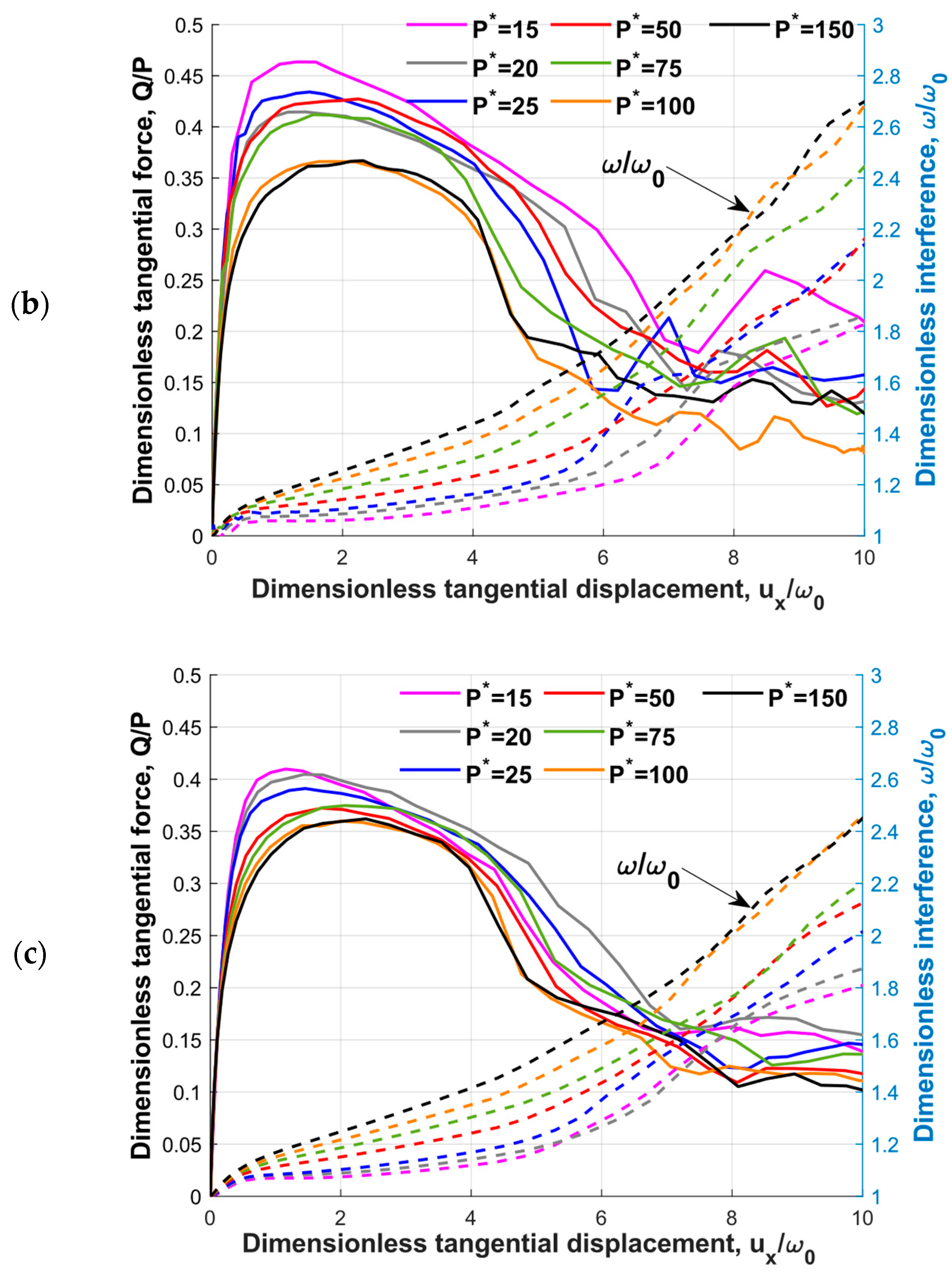
Figure 5 presents the results for the dimensionless tangential load Q / P and the dimensionless interference ω / ω 0 vs. the dimensionless tangential displacement u x / ω 0 for different dimensionless normal loads P* and different radii R. Figure 5 demonstrates that the transient dimensionless tangential forces and interferences exhibited a similar trend for the given material properties under different sphere radii and normal loads.
The dimensionless tangential force curves exhibited a certain non-monotonic behavior, particularly following the formation of the wear particles. These non-monotonic fluctuations were caused by the inherent numerical error. More specifically, the deletion and recontacting of the elements on the newly generated surface during the tangential loading led to the observed non-monotonic fluctuations. While it was impossible to entirely eliminate these fluctuations, they were reduced by implementing a more refined mesh. Similar fluctuations were also reported in Ref. [13]. Figure 4 provides a comparison that demonstrates that the fluctuation levels were within an acceptable range when compared to the previously published results.
As shown in Figure 5, the curves for the larger sphere radius were more consolidated. This behavior was caused by the dimensionless sub-model parameters ( r s * , t s * ). Although these two parameters allowed for the wear particle formation, the sub-model geometry might not have been large enough to exclude the influence of the applied boundary conditions. A few simulations of R = 5 [mm] were carried out using larger geometry, and the friction behavior was close to the friction behavior of R = 50 [mm]. It should be noted that the wear volume and wear particle parameters had a slight difference, below 10%. Since, as will be shown, the dimensionless results were independent of the radius, it was more beneficial to look at the larger radii as long as the adhesion, which was associated with nano and micron scale, was not considered.
Furthermore, it can be observed that the dimensionless interference during tangential loading increased with the increase in the dimensionless normal load. This can be explained by the junction growth under the combined loading [29].
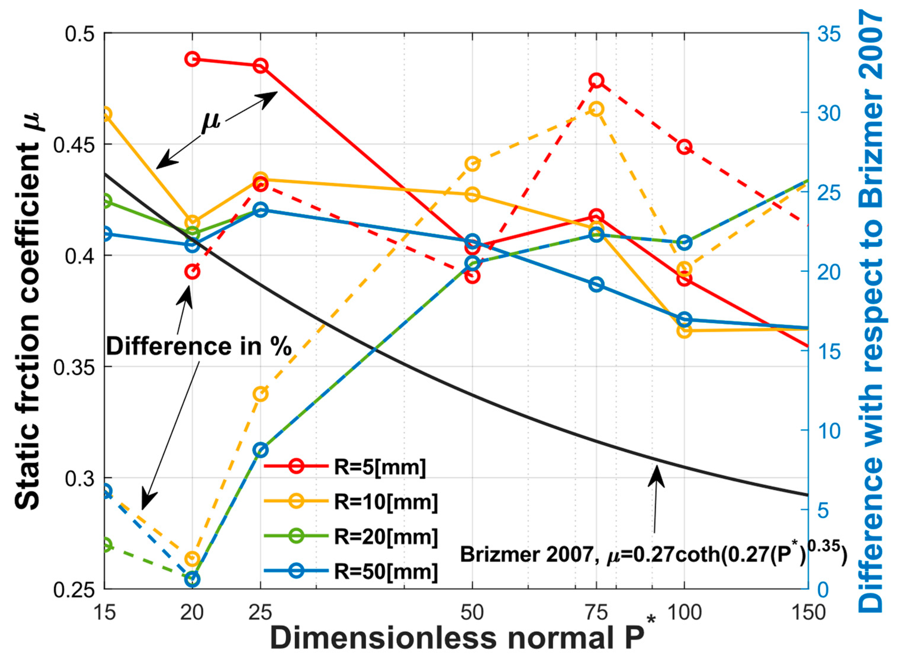
Figure 6 illustrates the maximum dimensionless tangential forces, which indicate the static friction coefficient corresponding to the different sphere radii plotted against the dimensionless normal load. In general, the static friction coefficient decreased with the increasing dimensionless normal load, which showed a consistent result with [17]. A comparison between the results presented in [17] is also shown in percentages by the dashed lines. The differences for the small normal load, 15 < P * < 25 , were lower than 10%; however, for the larger normal loads, 50 < P * < 150 , the differences became larger, but were no more than 35% with respect to [17].
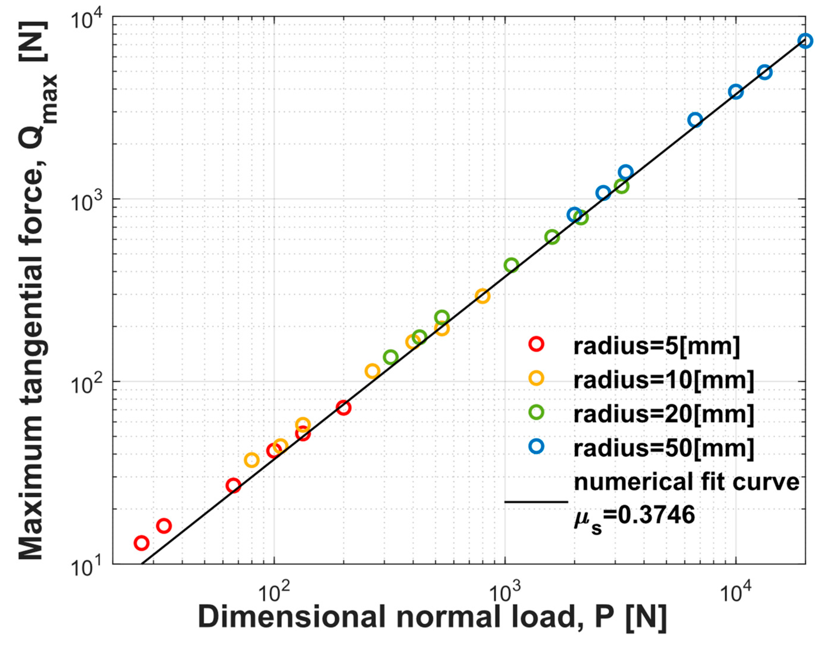
As shown in Figure 7, the maximum tangential force and the corresponding normal load are shown for the different sphere radii, where the different colors represent the different sphere radii.
A numerical fitted curve, in the black solid line, with Q m a x = μ s P resulted in μ s = 0.37 for all the simulations conducted in the current study, regardless of the sphere radius. Interestingly, in Rabinowicz [30], for 50 separate experiments with different material combinations, a lower limit for the friction coefficient, approx. 0.37, was reported.

4.3. Wear Characteristics

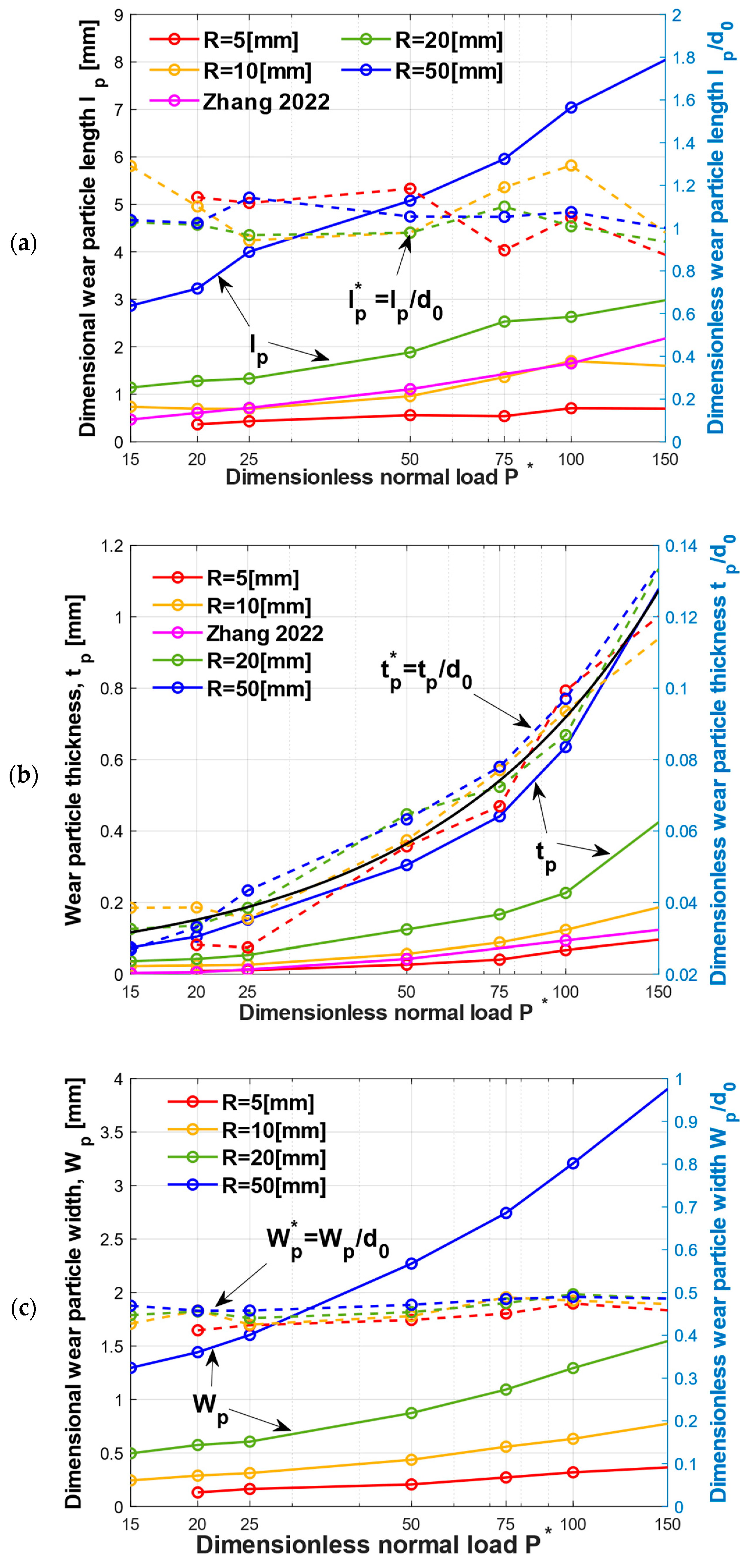
The effects of the normal load intensity and the sphere radius on the wear particle morphology and wear rate were also analyzed. The geometry of a typical wear particle is presented in Figure 3f and the obtained results for the wear particle length l p , thickness t p and half width W p are shown in Figure 8, in both dimensional and dimensionless manners. As shown in Figure 8, the dimensional and dimensionless parameters are indicated by the solid and the dashed lines, respectively. The same normalization as in [15] was adopted in the current study. All three wear particle parameters were normalized using the diameter of the contact area after the normal loading, d 0 , which is a function of the radius and the interference in the following formula [16].
d 0 = 2 ω 0 R
It can be seen in Figure 8 that all the dimensional parameters of the wear particle increased as P * increased, indicating that increasing the normal load led to an increase in the wear particle size.
A consolidation of the dimensionless results can be observed. With the increases in the dimensionless normal load, the dimensionless wear particle length remained constant at a value of one. The behavior of the dimensionless wear particle length in this study was in contrast to that reported in [15], where l p * was observed to increase with the dimensionless normal load caused by the junction growth. This difference can be attributed to the deletion of elements on the trailing edge of the contact surface in the current sub-model. Following the initiation of the crack, the element adjacent to the crack, as shown in Figure 3a, continued to be deleted from the wear particle. This deletion of the adjacent element ultimately resulted in a reduction in the wear particle length. Although some deletion occurred due to the small thickness at the trailing edge, it didn’t affect the prediction of the wear volume.
As shown in Figure 8b, the dimensionless wear particle thickness increased with the dimensionless normal load, and this behavior corelates well with [15]. The numerical curve fitting shown in the black solid line provided a function t p * with respect to the P * with a goodness of R 2 = 0.97 .
t p * = 7.1 e 4 P * + 0.021
It can be observed that the predicted thickness was slightly higher compared to the results in Ref. [15]. The differences in t p were caused by the differences in the obtained interferences in both sub-models. Including the rigid flat in the sub-model resulted in a slightly increased interference. As the interference increased, so did the size of the plastic region [31], forcing the crack to propagate more in the vertical direction and resulting in a thicker wear particle.
As shown in Figure 8c, the dimensionless wear particle half width was almost constant with a value of W p * = 0.5 , meaning half of the contact diameter d 0 . This was due to the growth of the junctions primarily affecting the contact area in the tangential loading direction, which was perpendicular to the width direction of the wear particle. As a result, the wear particle width remained unchanged.
The wear volume V p is defined as the volume of the wear particle. The wear rate w represents the wear volume per unit of tangential displacement, and it could be used for surface wear evaluation.
The wear rate is given by the following equation.
w = V p / s
where s is the sliding distance when the wear particle is fully detached from the sphere and is calculated as the following.
s = u p + l p
where u p is the tangential displacement of the rigid flat when the wear particle is formed. It is noteworthy that the simulation ran until the tangential displacement of u p and not s was achieved. With this method, the computational time can be reduced while ensuring a more realistic result. Obtaining a complete detachment of the wear particles by defining the sliding distance for the simulation required an extensive computational time and led to an unphysical wear volume. This was because the element deletion driven by the JC criterion and fracture energy continued after the wear particle was fully formed (at tangential displacement u p ). This led to an additional element removal from the wear particle during the detachment. Consequently, the wear volume for the complete detachment was smaller than the wear particle volume V p when it was just formed. The previous studies on the adhesive wear also utilized the same concept [13,15,32].
Figure 9 presents the results of the wear volume V p and the wear rate w for the various dimensionless normal loads P * and different sphere radii R. The wear volume was normalized by the hemisphere volume, V p * = V p / V 0 , where V 0 = 2 π R 3 / 3 . The wear rate was normalized term by term, where the nominator was normalized by the hemisphere volume and the denominator was normalized by ω 0 .
w * = V p * / ( ( u p + l p ) / ω 0 )
This normalization led to a general relation between the dimensionless wear rate w * and the dimensionless normal load P * , allowing for the prediction of the wear rate and the wear volume independent of the radius for aluminum 2024 T351. The only parameter required to obtain the dimensionless wear rate was ω 0 , which can be calculated by following equation [33].
P * = ω * 3 / 2 1 exp 1 1 ω * β
where β is the linear function of Poisson’s ratio, β = 0.174 + 0.08 ν , and ω * is normalized by the critical interference δ c for the stick contact condition, given by [33].
δ c / ω c = 6.82 ν 7.83 ν 2 + 0.0586
where ω c is the critical interference at the yield inception for a slip contact condition [33].
ω c = C v π 1 ν 2 2 Y E 2 R
Figure 9a shows that the wear volume increased as P * and R increased. The dimensionless wear volume curves were consolidated. In order to demonstrate the relation between V p * and P * , a numerical curve fitting with a goodness of R 2 = 0.997 was given as following equation.
V p * = 3.819 × 10 9 P * 2
By using Equation (15) and the normalization V p * = V p / V 0 , the dimensional wear volume can be calculated. The obtained result corelated well with the result in [15], with a difference less than 9%.
Figure 9b shows a similar behavior for the wear volume. The relation between w * and P * were given by a numerical fitted curve with a goodness of R 2 = 0.989.
w * = 6.39 × 10 12 P * 2.5
By substituting Equations (12)–(14) into Equation (16), the dimensional wear rate can be calculated. The presented model deals with the creation of a wear particle from a well-defined spherical asperity. The other shapes of the contacting asperities or post-abrasive asperities were not examined in the present study.
Since there is an exchange of asperities in in the contact between rough surfaces in relative motion during the tangential displacement, and assuming that all these asperities are spherical, the wear rate for the entire rough surface was derived from the uniformed dimensionless result of one asperity obtained in this study.
The power-law dependency on the dimensionless normal load for the wear rate reported in [15] is given by the following equation.
w = 3.26 × 10 5 P * 1.54
The dimensionless relation obtained in the current study had the power of 2.5 in P * term. The reason for this difference was the normalization used for the dimensionless wear rate. The normalization used for the dimensionless wear rate was w * = ( V P / V 0 ) / ( s / ω 0 ) . The denominator was normalized by ω 0 , which was affected by the dimensionless normal load, as shown in Equation (12). The numerator was normalized by V 0 , which was a constant. Hence, in Equation (16), a higher power on P * term was obtained.
To verify the expression obtained above, a simulation using the sphere radius, R = 15   [ m m ] , was carried out for a dimensionless normal P * = 100 . The dimensionless wear rate was 6.754 × 10⁻⁷, and the relative difference between the simulation result and the predicted results from Equation (16) was approx. 2.5%.
In Ref. [15], a transition region was observed for the wear rates. Three regimes of the wear rate with different exponents of P * were identified, which were P * 20 , 20 < P * 30 and P * 30 , representing the mild wear, transition region and severe wear, respectively. However, with the improved sub-model, this transition region was not observed. The power-law dependency on the dimensionless normal load for the wear rate w in the current study is given by following equation.
w = 4.6 × 10 5 P * 1.5 , P * < 30 w = 2.74 × 10 5 P * 1.6 , P * > 30
The change in the power of P * was not as significant between the two regions compared to what was reported in [15]. This difference was due to the different boundary condition at the contact surface of the sub-model. The deformation distribution used on the contact surface in [15] did not include the crack initiation and propagation, resulting in a smaller interference for the same normal load in the transition region. For instance, for R = 10 [mm] with P * = 25 , the dimensionless interference when the wear particle was formed ω p * = ω p / ω 0 was 1.2 in [15], while in the current study ω p * = 2.1 .

4.4. Parametric Study for the Material Properties

The results presented above were limited to a specific material, aluminum 2024 T351. To obtain a more general understanding of how the material properties affected the wear particle formation and mechanical behavior, a parametric study was utilized. The initiation and propagation of a crack was influenced by the three coefficients D 1 , D 2   a n d   D 3 in the JC failure model and by the fracture energy G f .
The range of the studied coefficients D 1 and D 2 was from 0.05 to 0.2, and D 3 ranging from −1 to −2. These ranges covered the changes of approx. 50% of the original values for the aluminum analyzed in the current study. However, different materials can have values outside this range, for example FeCoNiCr high entropy alloy [34] had values of D 1 = 0.004 , D 2 = 0.665 , and D 3 = 1.5 and free-cutting steel 50SiB8 [35] had values of D 1 = 0.0733 , D 2 = 0.7204 , and D 3 = 1.5643 .
The effect of D 1 on the friction behavior and wear volume V p was very small, and the maximum difference of the static friction coefficient and wear volume was less than 5% and 6%, respectively, for the range of the tested D 1 values. D 2 had a relatively large influence on the wear volume. The maximum change in the wear volume was 30% for the smallest value of D 2 .
For D 1 and D 2 , the most affected result was the wear particle thickness t p . As these two parameters decreased, t p increased. As shown in Equation (3), D 1 and D 2 influenced the equivalent plastic strain in the same way. As D 1 and D 2 decreased, ε f decreased. For the spherical contact under normal loading, the stress triaxiality σ * had a negative value as the element was being compressed, and it increased with the distance from the contact surface. This implies that the equivalent plastic strain for the crack generation decreased with an increasing distance from the contact surface. By reducing ε f , the crack propagation in the vertical direction became higher. Hence, the wear particle thickness increased as D 1 and D 2 decreased.
For the influence of D 3 , the most affected values were u p and V p . A maximum increases in u p about 60% was observed, compared to the original values of u p and V p for the smallest value of D 3 . As D 3 decreased, the equivalent plastic strain increased for the negative value of σ * , meaning that a larger strain is need for the element deletion, which explains the increase in u p . The wear volume change was caused by an additional element deletion during the larger tangential displacement., which may have resulted in fewer physical results.
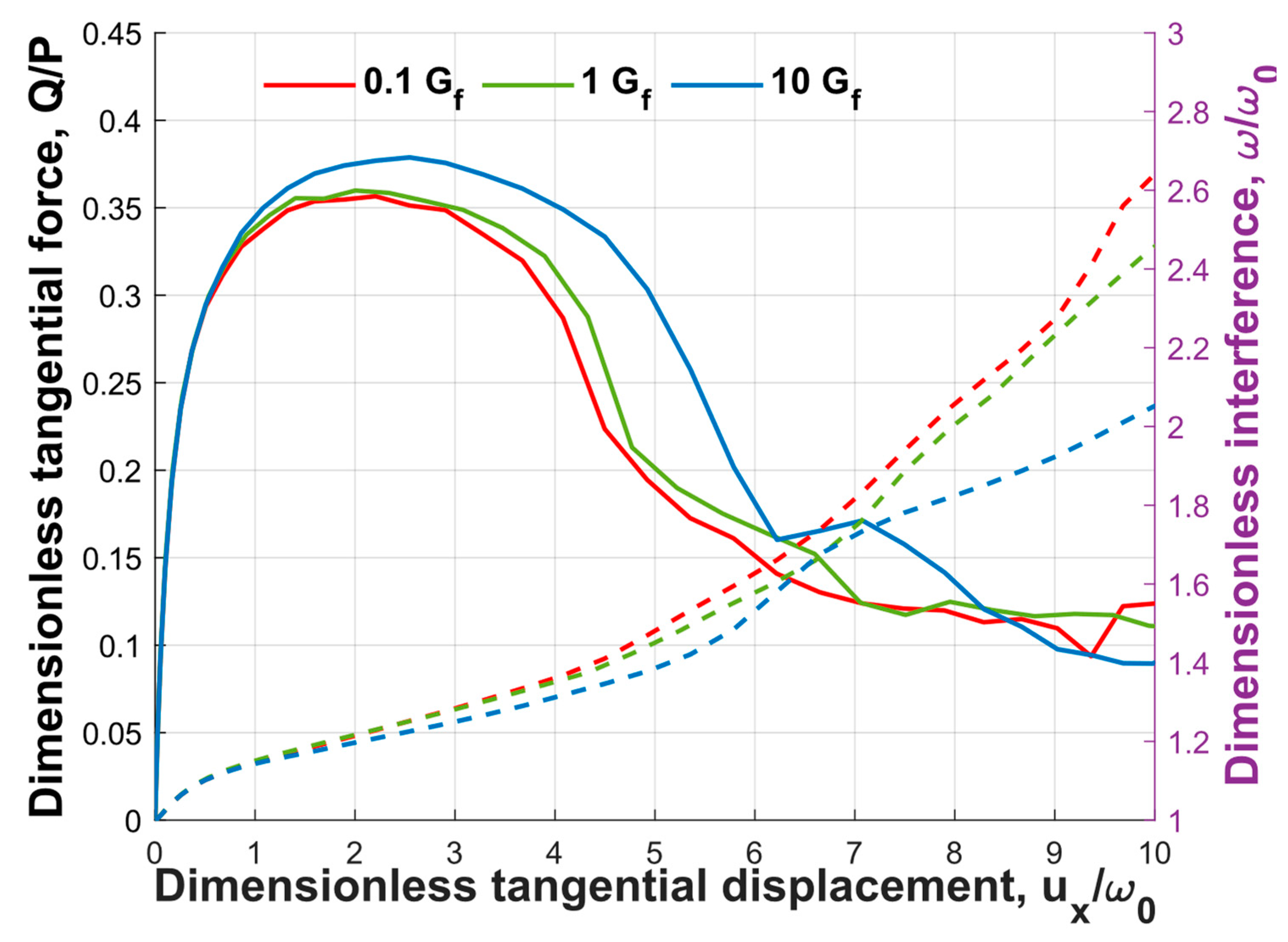
Figure 10 displays the friction behavior and dimensionless interference for various values of the fracture energy. While the JC parameters were more available in the literature, the same was not observed for the fracture energy. Hence, for the current parametric study on G f , a range spanning two orders of magnitude around the fracture energy of aluminum was used. It is important to note that the fracture energy values shown in Figure 10 were normalized by the fracture energy of aluminum 2024 T351.
It can be observed from Figure 10 that the static friction coefficient increased with the fracture energy. As shown in Figure 3, the maximum value of the dimensionless tangential force, or the static friction coefficient, was achieved after the crack initiation. This suggests that the fracture energy had an impact on the static friction coefficient. Since the force required to open a crack increased with the fracture energy, the static friction increased as well. However, it should be noted that the influence of the fracture energy was relatively small, with a maximum difference of only 6.2% observed between the two orders of magnitude of the fracture energy.
In contrast, the dimensionless interference decreased with the fracture energy. The change in the interference consisted of two contributors, namely the junction growth and element deletion. With an increase in the fracture energy, the number of elements deleted decreased, leading to a reduction in the dimensionless interference.
While changing D 1 , D 2 , D 3 and G f caused some changes to the wear particle morphology, the wear particle formation process for the different parameters was similar to those presented in Figure 3.
However, for a different material, Ti-6Al-4V, a difference in the crack propagation behavior was observed, as presented in Figure 11. The material properties were [36]: E = 110   G p a , ν = 0.33 , Y = 880   M p a and a density of ρ = 4430   K g / m 3 . The JC criterion [36] and the fracture energy [37] were: D 1 = 0.09 , D 2 = 0.25 , D 3 = 0.5 and G f = 47   K J / m 2 .
As shown in Figure 11, at instant I A , a crack was generated on the trailing edge of the contact surface. At instant I B , the tangential force reached its maximum. These two stages are similar to Figure 3. However, at instant I C , instead of a crack generated below the leading edge of the contact surface, the crack propagated along the edge of the contact surface and reached the leading edge. Interestingly, at I D , a second crack was generated within the contact surface surrounded by the first crack. As the tangential displacement increased, the second crack linked with the crack at the trailing edge of the contact surface and led to the formation of a wear particle at instant I E .
Since it was not observed that changing the JC coefficients or fracture energy led to such changes in the wear particle formation process, it was assumed that this new crack propagation may have been caused by the change in E / Y . For aluminum 2024 T351 E / Y = 227 and for Ti-6Al-4V, this value was E / Y = 125 .

5. Conclusions

An efficient FE model was presented for adhesive spherical contact under combined normal loading and tangential displacement. The model consisted of a global model that helped determine the potential fracture location and a sub-model with a refined mesh for the precise prediction of the wear particle formation. The improved sub-model included the rigid flat and two criteria were employed to simulate the crack initiation and propagation. Thus, the present sub-model inherited the efficiency of the sub-model introduced in the literature and the capability to predict the tangential mechanical response.
The current study primarily focused on the effects of the sphere radius and a range of relatively high normal loads on the wear particle evolution. However, the developed method can be extended to the wear simulations under various parameter combinations, including the materials, operating conditions, etc. The main contributions of the present study were the unified dimensionless relation between the dimensionless wear rate and the dimensionless normal load for the sphere radius varying from 5 to 50 [mm], as well as the insights gained into how the JC parameters and material properties (E/Y) affect the friction and wear behaviors. The obtained relations for the wear volume and wear rate may be generalized for the wider range of mechanical properties with the presented efficient sub-model.
Furthermore, the present method offers the possibility of extending the single spherical wear model to the adhesive wear prediction for rough surfaces and for fretting wear modeling. Nevertheless, the modeling of the adhesive wear can be improved by introducing a physical approach for the crack propagation, which is not based on element deletion. Such an approach would provide a more realistic and physically based simulation of the crack propagation and wear particle formation.

Author Contributions

Conceptualization, M.L. and R.G.; writing—original draft preparation, M.L.; writing—review and editing, G.X. and R.G.; supervision, R.G. All authors have read and agreed to the published version of the manuscript.

Funding

This research received no external funding.

Data Availability Statement

Not applicable.

Acknowledgments

The present study is supported by the Israel Academy of Sciences and Humanities and the Council for Higher Education Excellence Fellowship Program for International Postdoctoral Researcher. This paper is part of the IEA AMT IA technical activities.

Conflicts of Interest

The authors declare that they have no known competing financial interests or personal relationships that could have appeared to influence the work reported in this paper.

Nomenclature

a mesh size
c characteristic width of crack
d asperity radius
E Young’s modulus
G F size-independent fracture energy
G f fracture energy
H hardness
K Archard’s wear coefficient
L c critical load at yield inception under full stick contact condition
L sliding distance for Archard’s wear model
l p length of wear particle
P normal load
P * dimensionless normal load, P * = P / L c
R sphere radius
r section I radius
s sliding distance
t section I thickness
t p thickness of wear particle
u p tangential displacement when wear particle is formed
u x tangential displacement
V 0 volume of original hemisphere, V 0 = 2 / 3 π R 3
V p volume of wear particle
W Archard’s wear volume
W p wear particle width
w wear rate
Y yield strength
υ Poisson’s ratio
ω interference
ω p interference when the wear particle is formed
Subscripts
0 at normal preloading
p wear particle
s sub-model
1 global model
Superscript
* dimensionless

References

  1. Devaraju, A. A critical review on different types of wear of materials. Int. J. Mech. Eng. Technol. 2015, 6, 77–83. [Google Scholar]
  2. Burwell, J.T.; Strang, C.D. On the empirical law of adhesive wear. J. Appl. Phys. 1952, 23, 18–28. [Google Scholar] [CrossRef]
  3. Molinari, J.-F.; Aghababaei, R.; Brink, T.; Frérot, L.; Milanese, E. Adhesive wear mechanisms uncovered by atomistic simulations. Friction 2018, 6, 245–259. [Google Scholar] [CrossRef]
  4. Archard, J. Contact and rubbing of flat surfaces. J. Appl. Phys. 1953, 24, 981–988. [Google Scholar] [CrossRef]
  5. Holm, R. Electric Contacts: Theory and Application; Springer Science & Business Media: New York, NY, USA, 2013. [Google Scholar]
  6. Bowden, F.P.; Tabor, D. The Friction and Lubrication of Solids; Oxford University Press: Oxford, UK, 2001. [Google Scholar]
  7. Zhang, H.; Goltsberg, R.; Etsion, I. Modeling Adhesive Wear in Asperity and Rough Surface Contacts: A Review. Materials 2022, 15, 6855. [Google Scholar] [CrossRef]
  8. Hills, D.A.; Ashelby, D.W. On the application of fracture mechanics to wear. Wear 1979, 54, 321–330. [Google Scholar] [CrossRef]
  9. Fleming, J.R.; Suh, N.P. Mechanics of crack propagation in delamination wear. Wear 1977, 44, 39–56. [Google Scholar] [CrossRef]
  10. Suh, N.P. The delamination theory of wear. Wear 1973, 25, 111–124. [Google Scholar] [CrossRef]
  11. Johnson, G.R.; Cook, W.H. Fracture characteristics of three metals subjected to various strains, strain rates, temperatures and pressures. Eng. Fract. Mech. 1985, 21, 31–48. [Google Scholar] [CrossRef]
  12. Wu, A.; Shi, X. Numerical investigation of adhesive wear and static friction based on the ductile fracture of junction. J. Appl. Mech. 2013, 80, 041032. [Google Scholar] [CrossRef]
  13. Zhang, H.; Etsion, I. Evolution of adhesive wear and friction in elastic-plastic spherical contact. Wear 2021, 478, 203915. [Google Scholar] [CrossRef]
  14. Hillerborg, A.; Modéer, M.; Petersson, P.-E. Analysis of crack formation and crack growth in concrete by means of fracture mechanics and finite elements. Cem. Concr. Res. 1976, 6, 773–781. [Google Scholar] [CrossRef]
  15. Zhang, H.; Etsion, I. An advanced efficient model for adhesive wear in elastic—Plastic spherical contact. Friction 2022, 10, 1276–1284. [Google Scholar] [CrossRef]
  16. Brizmer, V.; Kligerman, Y.; Etsion, I. The effect of contact conditions and material properties on the elasticity terminus of a spherical contact. Int. J. Solids Struct. 2006, 43, 5736–5749. [Google Scholar] [CrossRef]
  17. Brizmer, V.; Kligerman, Y.; Etsion, I. Elastic–plastic spherical contact under combined normal and tangential loading in full stick. Tribol. Lett. 2007, 25, 61–70. [Google Scholar] [CrossRef]
  18. Hancock, J.W.; Mackenzie, A.C. On the mechanisms of ductile failure in high-strength steels subjected to multi-axial stress-states. J. Mech. Phys. Solids 1976, 24, 147–160. [Google Scholar] [CrossRef]
  19. Liu, X.; Ma, H.; Fan, F. Modified Johnson–Cook model of SWRH82B steel under different manufacturing and cold-drawing conditions. J. Constr. Steel. Res. 2021, 186, 106894. [Google Scholar] [CrossRef]
  20. Murugesan, M.; Jung, D.W. Johnson Cook material and failure model parameters estimation of AISI-1045 medium carbon steel for metal forming applications. Materials 2019, 12, 609. [Google Scholar] [CrossRef]
  21. Hu, X.; Wittmann, F. Size effect on toughness induced by crack close to free surface. Eng. Fract. Mech. 2000, 65, 209–221. [Google Scholar] [CrossRef]
  22. Hu, X.-Z. An asymptotic approach to size effect on fracture toughness and fracture energy of composites. Eng. Fract. Mech. 2002, 69, 555–564. [Google Scholar] [CrossRef]
  23. Systèmes, D. Abaqus 6.9 User’s Guide and Theoretical Manual; Hibbitt, Karlsson & Sorensen, Inc.: Providence, RI, USA, 2009. [Google Scholar]
  24. Nahshon, K.; Pontin, M.; Evans, A.; Hutchinson, J.; Zok, F. Dynamic shear rupture of steel plates. J. Mech. Mater. Struct. 2007, 2, 2049–2066. [Google Scholar] [CrossRef]
  25. Mabrouki, T.; Girardin, F.; Asad, M.; Rigal, J.-F. Numerical and experimental study of dry cutting for an aeronautic aluminium alloy (A2024-T351). Int. J. Mach. Tools Manuf. 2008, 48, 1187–1197. [Google Scholar] [CrossRef]
  26. Wierzbicki, T.; Bao, Y.; Lee, Y.-W.; Bai, Y. Calibration and evaluation of seven fracture models. Int. J. Mech. Sci. 2005, 47, 719–743. [Google Scholar] [CrossRef]
  27. Abdelhafeez, A.M.; Soo, S.L.; Aspinwall, D.; Dowson, A.; Arnold, D. A coupled Eulerian Lagrangian finite element model of drilling titanium and aluminium alloys. SAE Int. J. Aerosp. 2016, 9, 198. [Google Scholar] [CrossRef]
  28. Asad, M.; Mabrouki, T.; Ijaz, H.; Khan, M.A.; Saleem, W. On the turning modeling and simulation: 2D and 3D FEM approaches. Mech. Ind. 2014, 15, 427–434. [Google Scholar] [CrossRef]
  29. Brizmer, V.; Kligerman, Y.; Etsion, I. A model for junction growth of a spherical contact under full stick condition. J. Tribol. 2007, 129, 783–790. [Google Scholar] [CrossRef]
  30. Rabinowicz, E.; Tanner, R.I. Friction and wear of materials. J. Appl. Mech. 1966, 33, 479. [Google Scholar] [CrossRef]
  31. Kogut, L.; Etsion, I. Elastic-plastic contact analysis of a sphere and a rigid flat. J. Appl. Mech. 2002, 69, 657–662. [Google Scholar] [CrossRef]
  32. Zhang, J.; Alpas, A.T. Transition between mild and severe wear in aluminium alloys. Acta Mater. 1997, 45, 513–528. [Google Scholar] [CrossRef]
  33. Brizmer, V.; Zait, Y.; Kligerman, Y.; Etsion, I. The effect of contact conditions and material properties on elastic-plastic spherical contact. J. Mech. Mater. Struct. 2006, 1, 865–879. [Google Scholar] [CrossRef]
  34. Bobbili, R.; Madhu, V. A modified Johnson-Cook model for FeCoNiCr high entropy alloy over a wide range of strain rates. Mater. Lett. 2018, 218, 103–105. [Google Scholar] [CrossRef]
  35. Gerstgrasser, M.; Smolenicki, D.; Akbari, M.; Klippel, H.; Roelofs, H.; Cadoni, E.; Wegener, K. Analysis of two parameter identification methods for original and modified Johnson-Cook fracture strains, including numerical comparison and validation of a new blue-brittle dependent fracture model for free-cutting steel 50SiB8. Theor. Appl. Fract. Mech. 2021, 112, 102905. [Google Scholar] [CrossRef]
  36. Zhang, Y.; Outeiro, J.C.; Mabrouki, T. On the selection of Johnson-Cook constitutive model parameters for Ti-6Al-4 V using three types of numerical models of orthogonal cutting. Procedia CIRP 2015, 31, 112–117. [Google Scholar] [CrossRef]
  37. Shrestha, S.; El Rassi, J.; Kannan, M.; Morscher, G.; Gyekenyesi, A.L.; Scott-Emuakpor, O.E. Fracture toughness and fatigue crack growth rate properties of AM repaired Ti–6Al–4V by Direct Energy Deposition. Mater. Sci. Eng. A 2021, 823, 141701. [Google Scholar] [CrossRef]
Figure 1. Adhesive wear of the spherical contact with a rigid flat (a) schematic and (b) cross section (plane y = 0) of the wear particle, taken from [13].
Lubricants 11 00228 g001
Figure 2. Global model with a mesh design, the improved sub-model assembly and boundary condition: (a) global model with a mesh design, (b) location of the improved sub-model with sub-model parameters, (c) boundary conditions.
Lubricants 11 00228 g002
Figure 3. Evolution of the fracture, from instants I A to I E for R = 10   [ m m ] , P * = 100 .
Lubricants 11 00228 g003
Figure 4. Dimensionless tangential force Q / P and dimensionless interference ω / ω 0 vs. dimensionless tangential displacement u x / ω 0 for R = 10 [mm], P * = 100 , comparing with Ref. [13].
Lubricants 11 00228 g004
Figure 5. Dimensionless tangential load Q / P and dimensionless interference ω / ω 0 vs. dimensionless tangential displacement u x / ω 0 for different normal loads and radii R, (a) R = 5 [mm], (b) R = 10 [mm], (c) R = 50 [mm].
Lubricants 11 00228 g005aLubricants 11 00228 g005b
Figure 6. Static friction μ vs. dimensionless normal load P * for the different radii and comparison with Ref. [17].
Lubricants 11 00228 g006
Figure 7. Maximum tangential force vs. normal load for the different radii and different normal loads.
Lubricants 11 00228 g007
Figure 8. Wear particle geometrical characteristics: (a) wear particle length, (b) wear particle thickness, (c) wear particle half width, presented in both dimensional and dimensionless manners, comparing with Ref [15].
Lubricants 11 00228 g008
Figure 9. (a) Wear volume V P and dimensionless wear volume V p * = V p / V 0 ; (b) wear rate w = V p / s and dimensionless wear rate w * = V p * / ( ( u p + l p ) / ω 0 ) .
Lubricants 11 00228 g009
Figure 10. Dimensionless tangential load Q / P and dimensionless interference ω / ω 0 vs. dimensionless tangential displacement u x / ω 0 for the different fracture energies.
Lubricants 11 00228 g010
Figure 11. Crack propagation for Ti-6Al-4V. R = 10 and P * = 50.
Lubricants 11 00228 g011
Table 1. Geometrical and mesh parameters used in the global and improved sub-model.
P * r 1 * ( r 1 / R ) t 1 * ( t 1 / R ) a 1 * ( a 1 / R ) r s * ( r s / R ) t s * ( t s / R ) a s * ( a s / R )
150.10.0150.00150.070.0085 × 10−4
20 to 300.10.0180.0020.080.0126 × 10−4
500.130.0220.0020.10.027 × 10−4
750.20.050.0030.140.0260.001
1000.20.050.0040.150.0380.001
1500.250.070.0040.190.050.002
Disclaimer/Publisher’s Note: The statements, opinions and data contained in all publications are solely those of the individual author(s) and contributor(s) and not of MDPI and/or the editor(s). MDPI and/or the editor(s) disclaim responsibility for any injury to people or property resulting from any ideas, methods, instructions or products referred to in the content.