Abstract
The gas–liquid miscible backflow pumping seal (G-LMBPHS) is a non-contact mechanical seal that is suitable for high-speed bearing chambers. However, the tribological properties and wear mechanisms of the frictional pair of G-LMBPHS in an oil–air environment have not yet been comprehensively studied. In this study, the tribological properties of six frictional pairs, consisting of three hard materials (18Cr2Ni4WA, Al2O3 coating, and Cr2O3 coating) and two soft materials (metal-impregnated graphite [Metal-IG] and resin-impregnated graphite [Resin-IG]), were analyzed using a disc-on-disc tribometer. An oil–air environment was created using a minimal quantity lubrication (MQL) system and a closed chamber. The results show that the COF of the four frictional pairs consisting of two coatings and two graphites decreases gradually with increasing rotational speed, and the frictional pairs composed of Al2O3 coating and Resin-IG and Cr2O3 coating and Resin-IG have the lowest COF between 0.022 and 0.03. Therefore, the frictional pairs of G-LMBPHS are in a mixed lubrication condition. The lubricant in the oil–air environment is adsorbed and stored in pits on the surface of graphite and coatings, enhancing the hydrodynamic effect of the spiral grooves and reducing the COF by up to 45%. Metal-IG has better wear resistance than Resin-IG, and the frictional pair consisting of Cr2O3 coating and Metal-IG has the lightest wear. This study provides an important basis for the selection of G-LMBPHS frictional pairs in oil–air environments.
1. Introduction
Lubrication and sealing are critical factors that significantly influence the performance of rotating equipment. Typically, low-speed equipment utilizes grease lubrication and splash lubrication, while high-speed equipment, such as aero-engines and turbines, employs more advanced and effective forms of lubrication, including injection lubrication [1], under-ring lubrication [2], oil–air lubrication [3], and oil–mist lubrication [4]. The shift towards advanced lubrication techniques has not only increased the operational limits of bearings but has also magnified the importance of effective lubricant sealing. G-LMBPHS, a novel non-contact mechanical seal, has been developed for high-speed bearing chambers. This seal relies on the hydrodynamic effect of the spiral groove to establish non-contact of the sealing surface, thereby reducing frictional wear of the frictional pair. Additionally, the backflow pumping effect of the spiral groove is leveraged to achieve zero lubricant leakage [5]. However, during the start–stop process of the seal, the rotating ring and stationary ring surfaces of G-LMBPHS inevitably experience solid contact and friction for a brief period as they transition from contact to non-contact. Failure to use the appropriate seal ring material can result in the degradation of the seal ring and the accumulation of abrasive debris within the spiral groove, which can adversely impact the seal’s normal operation and possibly cause it to fail. Therefore, it is of utmost importance to investigate the tribological performance of seal ring materials to optimize seal performance and prolong seal life.
The issue of frictional wear in mechanical seals has been a major focus of research over the past few decades. Researchers have conducted extensive studies aimed at improving the tribological performance and wear resistance of these seals. Improvements in the overall performance of seal ring materials [6,7] and surface engineering techniques [8,9] have been commonly used to improve mechanical seals. In recent years, considerable efforts have been invested in developing new materials to meet the requirements of more demanding operating conditions and higher performance. Ceramics are frequently employed as seal ring materials [10,11,12], such as silicon carbide (SiC), tungsten carbide (WC), and alumina (Al2O3), due to their high hardness, wear resistance, and chemical stability.
Surface engineering techniques play a significant role in enhancing the performance of mechanical seals. These techniques can be broadly categorized into two types: surface weaving and hard coating. Surface weaving technology is typically used in mechanical seals with lubricants. It is the most effective technology for making lubricant flow with hydrodynamic pressure and storing a small amount of abrasive chips through the weaving structure, thereby reducing the friction coefficient and improving wear resistance. Hard coating technology is to process a layer of hard coating on the substrate surface through spraying, vapor deposition, and other methods, which can also improve the wear resistance of mechanical seals. Moreover, hard coating technology has a wide range of applications since the appropriate coating can be selected based on the lubrication conditions and lubricants. Ceramic materials are often used as surface coatings for ductile materials [13,14]; for example, Al2O3 coatings are commonly used for tail bearings [15] and propeller shafts [16], while chromium oxide (Cr2O3) coatings are commonly used for piston rings and cylinder liners in the automotive industry [12,17]. Ceramic materials are also commonly used as coating for mechanical seal surfaces.
Apart from the physical and chemical properties of the frictional pair materials, the friction conditions have a great influence on their tribological properties. Previous studies on the tribological performance of mechanical seal frictional pairs have mainly focused on dry friction, water lubrication, or oil lubrication [6,18,19,20,21]. Under dry friction, graphite tends to transfer to the friction surface, reducing the direct contact between the frictional pairs [22,23,24,25,26]. The COF of graphite is lower under water or oil lubrication than under dry friction [27,28,29]. However, the lubrication condition of G-LMBPHS differs from conventional mechanical seals and is dependent on the bearing lubrication method. Our previous studies [30] have shown that, at low speeds, the frictional pairs are lubricated by the oil–air two-phase fluid in the bearing chamber. At high speeds, the frictional pairs are hydrodynamic lubrication due to the backflow pumping action.
This study intends to investigate the tribological characteristics of frictional pairs in the oil–air environment during the start-up process of G-LMBPHS. To achieve this, a disc-on-disc tribometer was utilized to create an oil–air environment with a MQL system and a closed chamber. The start-up process of G-LMBPHS was simulated by applying a constant load and a step increase in rotational speed. The friction mechanisms of the frictional pairs were revealed by 3D optical surface analyzer and scanning electron microscope (SEM). The findings of this study serve as a crucial foundation for selecting the appropriate frictional pairs for G-LMBPHS in an oil–air environment.
2. Test Procedure
2.1. Seal Structure and Working Principle
Figure 1a,b show structure of G-LMBPHS and its spiral groove, respectively. The rotating ring, which houses the spiral groove, is made of a harder material to reduce wear, while the stationary ring is made of a softer material. During normal operation, the surfaces of the rotating and stationary rings do not come into contact, and the steady-state operating principle has been extensively discussed in the literature [5]. However, during the low-speed start–stop process, the rotating and stationary rings of G-LMBPHS experience a state of contact and friction for a certain period, similar to most non-contact mechanical seals [9]. The tribological properties of the materials used for the rotating and stationary rings directly affect the sealing performance and service life of the G-LMBPHS. However, the lubrication conditions of G-LMBPHS differ from those of other non-contact mechanical seals. The bearing chamber, where G-LMBPHS operates, contains an oil–air two-phase fluid that is created by mixing the lubricant ejected from the nozzle with the air inside the chamber under the action of the high-speed rotating bearing. The oil droplet diameter and oil droplet content in the oil–air two-phase fluid are influenced by factors such as oil injection volume, nozzle structure, and rotational speed [31,32]. Reportedly, the diameter of oil droplets in the oil–air two-phase fluid is 1 to 3 μm, making it possible to form an oil–air environment by a MQL system.
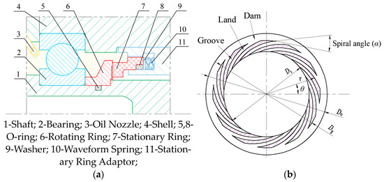
Figure 1.
Structure diagram of G-LMBPHS: (a) G-LMBPHS Structure; (b) structure of spiral groove.
2.2. Oil–Air Environment and Friction Tester
In this study, a Plint Tribology (TE-92, Phoenix Tribology Ltd., Berkshire, UK) was used to study the tribological properties of the G-LMBPHS frictional pair. The torque, COF, and temperature of the stationary ring were monitored during the test. The test device is shown in Figure 2a,b. One ring rotated with the shaft, while the other remained fixed at the bottom of the oil pool with a temperature sensor located near its friction surface. The friction surface was dry and free of lubricant before the test. The oil–air environment was constructed by an MQL system (KS-2106, KINS CO., Ltd., Shanghai, China). The oil used in the MQL system was Shell 555 turbine engine lubricant with a kinematic viscosity of 29.0 mm2/s at 37.8 °C. To avoid contamination of the environment by oil droplets, the oil pool outlet was connected to a filter, and a plastic film was wrapped between the top of the oil pool and the housing to seal the oil–air. During the test, the oil–air circulation is maintained and the percentage of lubricant in the oil–air is 4% (mass ratio).
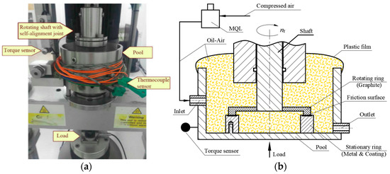
Figure 2.
Friction test for oil–air environment: (a) photograph of the tribometer; (b) schematic of test device for oil–air environment.
2.3. Frictional Pair Materials
The G-LMBPHS frictional pair usually adopts the pairing principle of hard ring to soft ring. Considering the material properties and the application, graphite was chosen as the soft material in this study. Resin and soft metals could improve the tribological properties of graphite materials [33,34,35,36,37], so typical Metal-IG and Resin-IG were selected as soft materials, as shown in Figure 3a,b. The inner and outer diameters of the friction surfaces are Ф 41.5 mm and Ф 50.0 mm, respectively. After grinding, the surface roughness of Metal-IG and Resin-IG was measured by ZYGO NexView 3D optical surface analyzer (Zygo Corporation, Connecticut, USA) to be 0.044 μm and 0.055 μm, respectively.
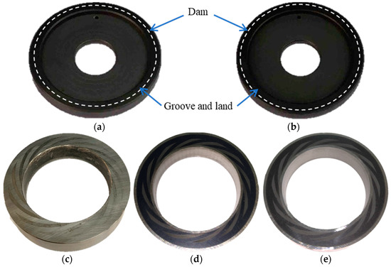
Figure 3.
Test ring: (a) Metal-IG; (b) Resin-IG; (c) 18Cr2Ni4WA; (d) 18Cr2Ni4WA + Al2O3 coating; (e) 18Cr2Ni4WA + Cr2O3 coating.
Since the high-speed bearing chamber may be subjected to loads such as shock and vibration, the ductile material 18Cr2Ni4WA was selected as the substrate and sprayed with Al2O3 ceramics and Cr2O3 ceramics on its surface for hard ring, as shown in Figure 3c–e. Although the theoretical hardness of Al2O3 and Cr2O3 is large, their actual hardness is affected by the microscopic defects generated during the machining process [38,39,40]. The inner and outer diameters of the hard rings are Ф 38.0 mm and Ф 54.0 mm, respectively. The material properties of the soft and hard rings are detailed in Table 1. The planarity of the test rings was measured by a flat light band tester (BY-150, BYJL CO., Ltd., Ningbo, China), and all the test rings showed 1~2 sodium light interference bands, indicating planarity of 0.3~0.6 µm. The parallelism of the test rings was measured by a 3D non-contact image measuring instrument (TM-151510CAZ, Beijing, China), and the parallelism of all the test rings was 0.008~0.015 mm.

Table 1.
Material properties of frictional pairs.
The structural parameters of the spiral grooves are detailed in Table 2. The spiral grooves were machined on the surface of the hard ring using a fiber laser machine (YLP-20, HANS LASER, Shenzhen, China), followed by surface polishing to eliminate any impurities. The depth of each spiral groove was measured within 4.8~5.6 μm using the 3D non-contact image measuring instrument. The surface roughness after polishing was 0.070 μm, 0.005 μm, and 0.021 μm for 18Cr2Ni4WA, Al2O3 coating, and Cr2O3 coating, respectively. The inner side of the white dashed line of the soft ring shown in Figure 3a,b represents to the groove and land of the hard ring, while the outer region corresponds to the dam.
Table 2.
Structure parameters.
2.4. Test Process
During the seal start-up process, the closing force remains constant while the rotational speed steadily increases. However, replicating this process on a friction tester poses a challenge. Therefore, to investigate the tribological properties of the seal ring material, the start-up process was approximated by subjecting the ring to a constant load and a step increase in rotational speed. Test conditions are presented in Table 3. Since the oil pool is open and cannot be loaded with fluid pressure, the closing force of G-LMBPHS was equated to a constant load on the test ring. Previous experimental studies [5] showed that the G-LMBPHS was in a contact friction state at a speed of 0 to 1000 r/min, in a transition stage from contact friction to non-contact between 1000 and 2000 r/min and in a non-contact operation when the speed exceeds 2000 r/min. Therefore, the maximum speed for the friction wear test was set at 2000 r/min, with an initial speed of 400 r/min. Each time increasing by 400 r/min, with each speed running steadily for 300 s, and three tests conducted for each material combination.
Table 3.
Test steps of accelerated process.
3. Tribological Results
3.1. Tribological Properties
The tribological properties of the six frictional pairs in the oil–air environment are shown in Figure 4. The COFs of 18Cr2Ni4WA and Metal-IG and 18Cr2Ni4WA and Resin-IG gradually increased with the increase of rotational speed, where the COF of 18Cr2Ni4WA and Metal-IG was the largest, reaching up to 0.083. Conversely, the COFs of the four frictional pairs composed of Al2O3 coating, Cr2O3 coating, Metal-IG, and Resin-IG gradually decreased with increasing rotational speed. This trend is consistent with Engqvist and Zhang’s study [20,25,41]. The COFs of Al2O3 coating and Metal-IG and Cr2O3 coating and Metal-IG at low speed were lower than that at dry friction [20], indicating that a small amount of lubricant in an oil–air environment can effectively improve the lubrication condition of the frictional pair and obtain a lower COF. Qiu [21] observed a COF phenomenon in oil lubrication, which first decreased and then increased with the rotational speed, and believed that the lubrication condition of the frictional pair changed from mixed lubrication to hydrodynamic lubrication. However, no similar phenomenon was observed in this study. The load and rotational speed in this study were greater than those of Qiu [21], implying that the small amount of lubricant in oil–air does not generate enough bearing capacity to bring the frictional pair into hydrodynamic lubrication under the action of the spiral groove Therefore, the frictional pair in the oil–air environment is in a mixed lubrication state. Among these four frictional pairs, the COF of the frictional pairs composed of Resin-IG with two coatings were smaller and smoother than those of the frictional pairs composed of Metal-IG. The COFs of Al2O3 coating and Resin-IG and Cr2O3 coating and Resin-IG were the smallest among the six frictional pairs, ranging from 0.022 to 0.3.
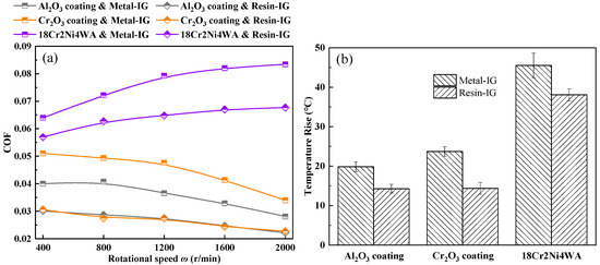
Figure 4.
Tribological properties of frictional pairs under oil–air environments: (a) COF vs. rotational speed; (b) Temperature vs. rotational speed.
In the oil–air environment, the temperature rise of the six frictional pairs was positively correlated with COF. The smaller the COF, the smaller the temperature rise of the frictional pairs, as shown in Figure 4b. Notably, Al2O3 coating and Resin-IG and Cr2O3 coating and Resin-IG exhibited the smallest COF and the lowest frictional temperature rise. Compared with dry friction [20], the temperature rise of the frictional pairs in the oil–air environment is lower at the same time at low speed. This can be attributed to two factors. Firstly, the COF of the frictional pair is lower in the oil–air environment. Secondly, the circulating oil–air dissipates some of the frictional heat, thereby decreasing the temperature rise of the frictional pair.
For commonly used frictional materials, an inverse correlation trend can be observed between the COF of the frictional pairs and the difference in hardness between the hard and soft materials, as shown in Figure 5. The four data points on the left side represent the frictional pairs composed of 18Cr2Ni4WA, Cr2O3 coating, Resin-IG, and Metal-IG, respectively. The COF of the frictional pairs decreases rapidly with an increase in the hardness difference between the materials. A similar phenomenon was observed in the study by Li [41]. Generally, the COF of the frictional pair is positively correlated with the load [42,43], and it can be concluded that the higher the contact pressure of the frictional pair, the higher the COF. Hard materials are less prone to plastic deformation, while soft materials are prone to plastic deformation. When two materials with a larger hardness difference are in contact, the softer material undergoes plastic deformation, resulting in a larger contact area and a more uniform contact pressure, and ultimately a smaller COF. Although the hardness difference between Al2O3 coating and Metal-IG and Al2O3 coating and Resin-IG was the largest, the COF of them increased slightly instead. In general, in the oil–air environment, a smaller COF of frictional pair can be obtained by selecting two materials with a larger hardness difference.
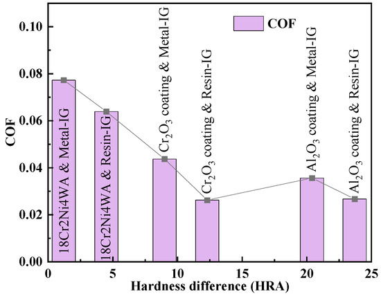
Figure 5.
Relationship between hardness difference and COF.
In the oil–air environment, the COF of the four frictional pairs consisting of Al2O3 coating and Cr2O3 coating gradually decrease with increasing speed [25,44], while the COF of the frictional pair of 18Cr2Ni4WA with graphite, on the contrary, gradually increases. This phenomenon can be attributed to three main reasons. Firstly, the lubricant on the friction surface maintains a dynamic equilibrium. The lubricant in the oil–air environment is constantly adsorbed to the friction surface, and the lubricant is constantly leaving the inner and outer sides of the friction surface under rotational speed and load, while carrying the graphite abrasive dust generated during the friction process. Secondly, the hydrodynamic effect of the spiral groove reduces the contact force on the friction surface. Thirdly, the micron-sized spiral groove is able to contain and discharge the abrasive dust, preventing them from continuously damaging the friction surface. The COF of the four frictional pairs consisting of Al2O3 coating and Cr2O3 coating rapidly decreases, while the slow increase in COF of the frictional pair of 18Cr2Ni4WA with graphite reflects the influence of these aspects. The COF of the four frictional pairs consisting of Al2O3 coating and Cr2O3 coating decreased by 2.4% to 3.8% when the speed was increased from 400 to 800 r/min, and decreased by 10.5% to 14.1% when the speed was increased from 1600 to 2000 r/min. The oil–air environment has a minimal effect on the hard coating because the coating and IG have a small COF, produces less abrasive dust, and the coating is less susceptible to wear. However, for 18Cr2Ni4WA and IG, the oil–air environment is unfavorable because 18Cr2Ni4WA is relatively soft and easy to wear, and because the graphite abrasive dust keeps leaving the friction surface with the lubricant, graphite is not easy to form a stable transfer film on the surface of 18Cr2Ni4WA [44], which further aggravates the wear of 18Cr2Ni4WA and leads to an increase in the COF. After the 18Cr2Ni4WA and IG test, a light black lubricant was observed in the oil pool, while the color of the lubricant after the tests of Al2O3 coating and IG and Cr2O3 coating and IG was almost unchanged, indicating that the coating can effectively reduce the wear of graphite.
3.2. Influence of Spiral Groove on Frictional Properties of Frictional Pairs
To further analyze the impact of material and spiral groove on the frictional properties of G-LMBPHS frictional pair, this study conducted frictional tests on grooveless surfaces under oil–air environment, and compared the results with those of grooved surfaces, as shown in Figure 6. At low speed, the COF of all the four grooveless frictional pairs was larger than that of the grooved frictional pairs. Except for the slight hydrodynamic effect of the spiral groove, the actual contact area of the grooved surface was 65% of the grooveless surface, and the contact force was 1.54 times that of the grooveless surface, resulting in lower COF values for the four grooved frictional pairs. The COF of the grooveless surface increased approximately linearly with increasing rotational speed. From the range of COF, the grooveless surface was in boundary lubrication under oil–air environment, indicating that a small amount of lubricant was adsorbed on the friction surface during the test. Graphite is a porous material, and despite the impregnation filling the pores, there were still some pits on the surface, as shown in Figure 7a,b. In contrast, both Al2O3 coating and Cr2O3 coating had a small number of pits on the surface due to machining defects, as shown in Figure 8b,c. These pits stored and confined the lubricant to maintain higher pressure and increase the hydrodynamic lubrication area [44], thus reducing the direct solid contact between the two surfaces and effectively reducing the adhesive wear of the frictional pairs. As the speed increases, the lubricant stored in the pits gradually decreased, and the lubrication condition of the frictional pair deteriorated, leading to a gradual increase in the COF.
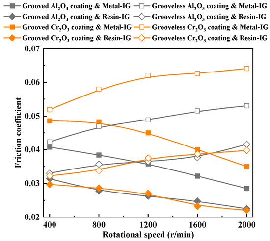
Figure 6.
COF of grooved and grooveless frictional pairs.
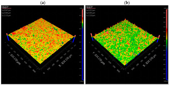
Figure 7.
Micromorphology of graphite before the test: (a) Metal-IG; (b) Resin-IG.
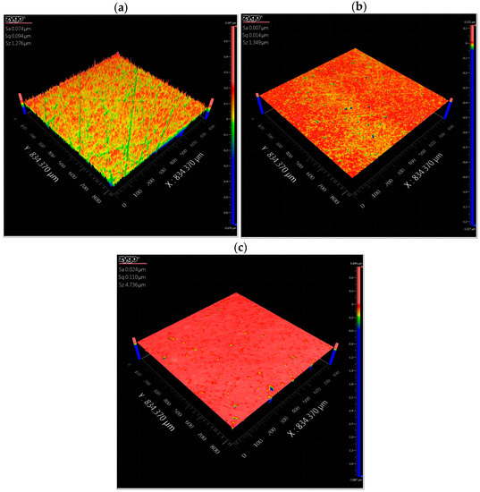
Figure 8.
Micromorphology of hard materials before the test: (a) 18Cr2Ni4WA; (b) Al2O3 coating; (c) Cr2O3 coating.
In contrast to the variation in COF observed on the grooveless surface, the COF of the grooved surface gradually decreased with increasing rotational speed. This indicated that the hydrodynamic effect of the spiral groove could effectively reduce the contact force of the frictional pairs as the rotational speed increases. According to the Stribeck curve, the grooved surface in the oil–air environment is in mixed lubrication, which aligns with the findings of Qiu’s study [21]. This phenomenon indicated that the amount of lubricant on the grooved surface was more than that on the grooveless surface, proving that the groove helped the lubricant to enter the friction surface. At a rotational speed of 2000 r/min, the spiral groove in oil–air environment can reduce the COF by about 45%.
3.3. Microscopic Morphology and Wear Mechanism
The surface micromorphology of Metal-IG and Resin-IG after the friction test is shown in Figure 9. Resin-IG has a lower hardness and exhibits more surface furrows, while Metal-IG has relatively higher hardness with fewer surface furrows but multiple deep pits, indicating that graphite under oil–air environment mainly undergoes abrasive wear accompanied by slightly adhesive wear. However, the difference in roughness between the two materials after testing is not significant.
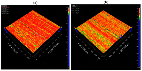
Figure 9.
Micromorphology of graphite after the test: (a) Metal-IG; (b) Resin-IG.
The SEM micrographs of the Metal-IG and Resin-IG after the friction testing are shown in Figure 10. Graphite is prone to wear due to its porous structure and poor mechanical properties. The surface of Metal-IG exhibited less flakes and marks than that of Resin-IG, indicating that Metal-IG has significant anti-wear properties. The mechanical properties of Resin-IG were poorer and the surface showed more severe abrasive wear accompanied by material spalling [42,45]. Zhao et al. [46] have demonstrated that Metal-IG exhibits a stable friction regime and superior anti-friction and anti-wear properties compared to Resin-IG. In addition, the impregnated material (metal or resin) can enhance the strength of the graphite matrix and promote the formation of graphite tribofilm on the corresponding surface, which is beneficial to reducing friction and wear.
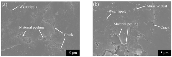
Figure 10.
Micromorphology of graphite after test: (a) Metal-IG; (b) Resin-IG.
The microscopic morphology of the three hard materials before and after the test is shown in Figure 11. Interestingly, the surface roughness after the test was observed to be smaller compared to that before the test, pointing towards the occurrence of abrasive wear and adhesive wear in 18Cr2Ni4WA. In contrast, minimal wear marks were observed on the surfaces of Al2O3 coating and Cr2O3 coating, indicating that the frictional pairs composed of hard coatings and graphite had good tribological properties in oil–air environments.
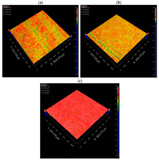
Figure 11.
Micromorphology of hard materials after the test: (a) 18Cr2Ni4WA; (b) Al2O3 coating; (c) Cr2O3 coating.
After the test, multiple furrows were observed on the Al2O3 coating rather than the Cr2O3 coating, which was not consistent with the respective hardness values. When Xiao [47] and Kumar [48] studied the sliding of hard metallic surfaces on graphite surfaces, furrows were also observed on the hard metallic surfaces. It is generally accepted that the furrows on hard surfaces come from abrasive wear of hard particles. Uchibori [49] attributed the furrows on hard surfaces to CaWO4 embedded in the graphite surface during sliding. Zhang [44] suggested that single crystal graphite in bulk graphite excises the hard surface bumps at a specific angle and these excised hard particles are embedded in the graphite and continuously plow the hard surface. The Young’s modulus of monocrystalline graphite has been reported to be up to 1025 GPa [50]. Comparing Figure 8b and Figure 11b, a few protrusions were observed on the Al2O3 coating after the test, while the ploughing was mainly found near some original pits. The protrusions on the surface of the Al2O3 coating are believed to be graphite adhering to the Al2O3 coating. Therefore, the abrasive particles may originate from the Al2O3 coating torn by the adhesion point. That is, when the graphite slides on the Al2O3 coating, the adhesion point is generated due to high contact stress. At the location where the bonding point of the Al2O3 coating is strong, the graphite side of the adhesion point fractures, and the graphite adheres to the Al2O3 coating to form a protrusion. While at the location where the bonding point of the Al2O3 coating is weak, the Al2O3 coating side of the adhesion point fractures and the hard particles formed are embedded in the graphite, thus continuously plowing the Al2O3 coating surface and forming abrasive wear. The additional abrasive wear is an important reason for the large COF of the Al2O3 coating. In contrast, the Cr2O3 coating is dense and there is little adhesive wear, and no obvious spalling of the Cr2O3 coating and abrasive wear are found. In summary, the selection of Cr2O3 coating and M120D as the frictional pair in oil–air environment can obtain both a smaller COF and less wear rate, which is very important for improving the service life and reliability of G-LMBPHS.
3.4. Wear of Graphite
Wear tests were conducted on four frictional pairs consisting of Al2O3 coating, Cr2O3 coating, Metal-IG, and Resin-IG, and the test procedure in Table 3 was repeated 24 times for each frictional pair, i.e., 10 h of friction tests were conducted for each frictional pair. The wear depth of the friction surface of graphite was assessed by calculating the mass loss of the graphite before and after the test, as shown in Figure 12.
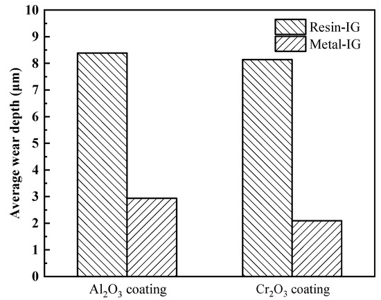
Figure 12.
Average wear depth of graphite for four frictional pairs.
Although the COF of two frictional pairs consisting of Metal-IG with two coatings is greater than that of Resin-IG with two coatings, Metal-IG has better wear resistance and less wear. This phenomenon is also consistent with the microscopic morphology of Metal-IG and Resin-IG. Metal-IG has better wear resistance, while Resin-IG has significant material spalling, which results in greater wear of Resin-IG than of Metal-IG. The wear of the frictional pair composed of Metal-IG and Al2O3 coating was greater than that of the frictional pair composed of Metal-IG and Cr2O3 coating. Since the denseness of Al2O3 coating is poorer than that of Cr2O3 coating, more abrasive particles are generated during the friction process, resulting in more intense wear of Metal-IG. Among the four frictional pairs, the wear of Cr2O3 coating and Metal-IG is the lightest. Assuming a single start-up process of G-LMBPHS is 5 minutes and allowing for 0.5 mm wear of the graphite ring, the frictional pair consisting of Cr2O3 coating and Metal-IG can sustain at least 15,000 start and stop processes.
4. Conclusions
The tribological properties of six different frictional pairs of G-LMBPHS in oil–air environments were investigated. The COF of four frictional pairs, which consisted of Al2O3 coating, Cr2O3 coating, Metal-IG, and Resin-IG, gradually decreased with the increasing rotational speed. Among the six pairs, the COF of the frictional pairs composed of Al2O3 coating and Resin-IG and Cr2O3 coating and Resin IG was the lowest, ranging from 0.022 to 0.03, exhibiting superior performance. The rise in temperature of the frictional pairs was positively correlated with the COF. The limited amount of lubricant in the oil–air did not provide sufficient load-bearing capacity under the action of spiral grooves, resulting in the frictional pairs of G-LMBPHS being in a mixed lubrication condition. With the increase of rotational speed, the hydrodynamic effect of the spiral groove can effectively reduce the contact force of the frictional pair. The spiral groove can reduce COF by up to 45% when the speed increases from 400 r/min to 2000 r/min. Metal-IG has better wear resistance than Resin-IG, and the frictional pair consisting of Cr2O3 coating and Metal-IG have the lightest wear.
Author Contributions
Conceptualization, S.L. (Shicong Liand); methodology, S.L. (Shicong Liand) and H.L.; validation, S.L. (Shicong Liand) and H.L.; formal analysis, S.L. (Shicong Liand); investigation, S.L. (Shicong Liand); resources, S.L. (Shicong Liand); data curation, S.L. (Shicong Liand); writing—original draft preparation, S.L. (Shicong Liand); writing—review and editing, J.Z.; visualization, S.L. (Shicong Liand); supervision, S.L. (Shuangxi Li); project administration, S.L. (Shuangxi Li). All authors have read and agreed to the published version of the manuscript.
Funding
This research was funded by the National Natural Science Foundation of China (No. 52275170) and the Tribology Science Fund of State Key Laboratory of Tribology in Advanced Equipment (SKLTKF21A04).
Data Availability Statement
Not applicable.
Conflicts of Interest
The authors declare no conflict of interest.
References
- Wu, W.; Hu, C.; Hu, J.; Yuan, S.H.; Zhang, R. Jet cooling characteristics for ball bearings using the VOF multiphase model. Int. J. Therm. Sci. 2017, 116, 150–158. [Google Scholar] [CrossRef]
- Adeniyi, A.A.; Morvan, H.P.; Simmons, K. A computational fluid dynamic simulation of oil-air flow between the cage and inner race of an aero-engine bearing. J. Eng. Gas Turbines Power 2017, 139, 012506. [Google Scholar] [CrossRef]
- Xie, J.; Jiang, S.Y.; Wang, X.S.; Feng, Y.D. Experiment research on oil-air lubrication for high-speed ball bearing. Lubr. Eng. 2006, 181, 114–119. [Google Scholar]
- Pinel, S.I.; Signer, H.R.; Zaretsky, E.V. Comparison between oil-mist and oil-jet lubrication of high-speed, small-bore, angular-contact ball bearings. Tribol. Trans. 2001, 44, 327–338. [Google Scholar] [CrossRef]
- Li, S.C.; Qian, C.F.; Li, S.X.; Li, Q.Z.; Liao, H.R. Study of sealing mechanism of gas-liquid miscible backflow pumping seal. Tribol. Int. 2020, 142, 105974. [Google Scholar] [CrossRef]
- Shankar, S.; Praveenkumar, G.; Kumar, P.K. Frictional study of alumina, 316 stainless steel, phosphor bronze versus carbon as mechanical seals under dry sliding conformal contact. Proc. Inst. Mech. Eng. Part J J. Eng. Tribol. 2015, 229, 1279–1291. [Google Scholar] [CrossRef]
- Liu, Y.; Zhao, X.Y.; Wen, Q.F.; Wang, Y.M. On frictional performance of sintering materials used by mechanical seals in water. Ind. Lubr. Tribol. 2014, 66, 23–30. [Google Scholar] [CrossRef]
- Wang, W.; He, Y.Y.; Zhao, J.; Mao, J.Y.; Hu, Y.T.; Luo, J.B. Optimization of groove texture profile to improve hydrodynamic lubrication performance: Theory and experiments. Friction 2020, 8, 83–94. [Google Scholar] [CrossRef]
- Chen, D.L.; Ding, X.X.; Yu, S.R.; Zhang, W.Z. Friction performance of DLC film textured surface of high pressure dry gas sealing ring. J. Braz. Soc. Mech. Sci. 2019, 41, 161. [Google Scholar] [CrossRef]
- Dong, S.J.; Song, B.; Hansz, B.; Liao, H.L.; Coddet, C. Microstructure and properties of Cr2O3 coating deposited by plasma spraying and dry-ice blasting. Surf. Coat. Technol. 2013, 225, 58–65. [Google Scholar] [CrossRef]
- Singh, V.P.; Sil, A.; Jayaganthan, R. Tribological behavior of plasma sprayed Cr2O3-3%TiO2 coatings. Wear 2011, 272, 149–158. [Google Scholar] [CrossRef]
- Monticelli, C.; Balbo, A.; Zucchi, F. Corrosion and tribocorrosion behaviour of cermet and cermet/nanoscale multilayer CrN/NbN coatings. Surf. Coat. Technol. 2010, 204, 1452–1460. [Google Scholar] [CrossRef]
- Monticelli, C.; Balbo, A.; Zucchi, F. Corrosion and tribocorrosion behaviour of thermally sprayed ceramic coatings on steel. Surf. Coat. Technol. 2011, 205, 3683–3691. [Google Scholar] [CrossRef]
- Ogwu, A.A.; Oje, A.M.; Kavanagh, J. Corrosion, ion release and Mott-Schottky probe of chromium oxide coatings in saline solution with potential for orthopaedic implant applications. Mater. Res. Express 2016, 3, 45401. [Google Scholar] [CrossRef]
- Keshri, A.K.; Agarwal, A. Wear behavior of plasma-sprayed carbon nanotube-reinforced aluminum oxide coating in marine and high-temperature environments. J. Therm. Spray Technol. 2011, 20, 1217–1230. [Google Scholar] [CrossRef]
- Mukherjee, B.; Rahman, O.S.A.; Islam, A.; Sribalaji, M.; Keshri, A.K. Plasma sprayed carbon nanotube and graphene nanoplatelets reinforced alumina hybrid composite coating with outstanding toughness. J. Alloys Compd. 2017, 727, 658–670. [Google Scholar] [CrossRef]
- Sadri, E.; Ashrafizadeh, F. Structural characterization and mechanical properties of plasma sprayed nanostructured Cr2O3-Ag composite coatings. Surf. Coat. Technol. 2013, 236, 91–101. [Google Scholar] [CrossRef]
- Shankar, S.; Kumar, P.K. Frictional characteristics of diamond like carbon and tungsten carbide/carbon coated high carbon high chromium steel against carbon in dry sliding conformal contact for mechanical seals. Mech. Ind. 2017, 18, 115. [Google Scholar] [CrossRef]
- Zhang, G.Y.; Dang, J.Q.; Zhao, W.G.; Yan, X.T. Tribological behaviors of the thick metal coating for the contact mechanical seal under the water-lubricated conditions. Ind. Lubr. Tribol. 2019, 71, 173–180. [Google Scholar] [CrossRef]
- Lu, J.; Wang, T.; Ding, X.; Song, H.; Li, H. Tribological performance of frictional pairs with different materials and bi-composite surface texture configurations. Appl. Sci. 2021, 11, 4738. [Google Scholar] [CrossRef]
- Qiu, Y.; Khonsari, M.M. Investigation of tribological behaviors of annular rings with spiral groove. Tribol. Int. 2011, 44, 1610–1619. [Google Scholar] [CrossRef]
- Zhao, J.; Li, Q.Z.; Li, S.X.; Li, S.C.; Chen, G.Y.; Liu, X.H.; He, Y.Y.; Luo, J.B. Influence of a carbon-based tribofilm induced by the friction temperature on the tribological properties of impregnated graphite sliding against a cemented carbide. Friction 2021, 9, 686–696. [Google Scholar] [CrossRef]
- Williams, J.A.; Morris, J.H.; Ball, A. The effect of transfer layers on the surface contact and wear of carbon-graphite materials. Tribol. Int. 1997, 9, 663–676. [Google Scholar] [CrossRef]
- Jin, K.; Qiao, Z.; Zhu, S.; Cheng, J.; Yin, B.; Yang, J. Friction and wear properties and mechanism of bronze-Cr-Ag composites under dry-sliding conditions. Tribol. Int. 2016, 96, 132–140. [Google Scholar] [CrossRef]
- Engqvist, H.; Hogberg, H.; Botton, G.A.; Ederyd, S.; Axen, N. Tribofilm formation on cemented carbides in dry sliding conformal contact. Wear 2000, 239, 219–228. [Google Scholar] [CrossRef]
- Hokao, M.; Hironaka, S.; Suda, Y.; Yamamoto, Y. Friction and wear properties of graphiter glassy carbon composites. Wear 2000, 237, 54–62. [Google Scholar] [CrossRef]
- Zhang, G.; Liu, Y.; Wang, Y.; Guo, F.; Liu, X.; Wang, Y. Wear behavior of WC-Ni sliding against graphite under water lubrication. J. Mater. Sci. Technol. 2017, 33, 1346–1352. [Google Scholar] [CrossRef]
- Guo, F.; Tian, Y.; Liu, Y.; Wang, Y. Ultralow friction between cemented carbide and graphite in water using three-step ring-on-ring friction test. Wear 2016, 352, 54–64. [Google Scholar] [CrossRef]
- Shankar, S.; Praveenkumar, G.; Krishnakumar, P. Experimental study on frictional characteristics of tungsten carbide versus carbon as mechanical seals under dry and eco-friendly lubrications. Int. J. Refract. Met. Hard Mater. 2016, 54, 39–45. [Google Scholar] [CrossRef]
- Li, Q.Z.; Li, S.X.; Zheng, R.; Zhong, J.F.; Li, S.C.; Liao, H.R. Test analysis on the opening process of oil-gas miscible reflux pumping seal. Aeroengine 2020, 46, 22–27. [Google Scholar]
- Fang, L.; Chen, G.D. The study of droplet deformation and droplet volume fraction in an aero-engine bearing chamber. Proc. Inst. Mech. Eng. Part G J. Aerosp. Eng. 2019, 233, 2264–2277. [Google Scholar] [CrossRef]
- Fei, W.; Chen, G.D.; Fu, Y.; Tao, W. Transient analysis of air/oil two-phase flow in bearing chamber under the periodic boundary conditions. MATEC Web Conf. 2017, 95, 06009. [Google Scholar] [CrossRef]
- Lafon-Placette, S.; Delbé, K.; Denape, J.; Ferrato, M. Tribological characterization of silicon carbide and carbon materials. J. Eur. Ceram. 2015, 35, 1147–1159. [Google Scholar] [CrossRef]
- Cao, H.M.; Zhou, X.; Li, X.Y.; Lu, K. Friction mechanism in the running-in stage of copper: From plastic deformation to delamination and oxidation. Tribol. Int. 2017, 115, 3–7. [Google Scholar] [CrossRef]
- Su, L.; Gao, F.; Han, X.; Chen, J. Effect of copper powder third body on tribological property of copper-based friction materials. Tribol. Int. 2015, 90, 420–425. [Google Scholar] [CrossRef]
- Li, J.; Zhang, L.; Xiao, J.; Zhou, K. Sliding wear behavior of copper-based composites reinforced with graphene nanosheets and graphite. Trans. Nonferrous Met. Soc. China 2015, 25, 3354–3362. [Google Scholar] [CrossRef]
- Wang, Y.; Gao, Y.; Sun, L.; Li, Y.; Zheng, B.; Zhai, W. Effect of physical properties of Cu-Ni-graphite composites on tribological characteristics by grey correlation analysis. Results Phys. 2017, 7, 263–271. [Google Scholar] [CrossRef]
- Sobhanverdi, R.; Akbari, A. Porosity and microstructural features of plasma sprayed Yttria stabilized Zirconia thermal barrier coatings. Ceram. Int. 2015, 41, 14517–14528. [Google Scholar] [CrossRef]
- Ghazali, M.J.; Forghani, S.M.; Hassanuddin, N.; Muchtar, A.; Daud, A.R. Comparative wear study of plasma sprayed TiO2 and Al2O3-TiO2 on mild steels. Tribol. Int. 2016, 93, 681–686. [Google Scholar] [CrossRef]
- Karthikeyan, S.; Balasubramanian, V.; Rajendran, R. Developing empirical relationships to estimate porosity and microhardness of plasma-sprayed YSZ coatings. Ceram. Int. 2014, 40, 3171–3183. [Google Scholar] [CrossRef]
- Li, Z.T.; Zhou, R.; Hao, M.M.; Tian, J.; Zhang, N. Friction properties of impregnated graphite with 9Cr18 sealing frictional pair. Lubr. Eng. 2023, 48, 128–133. [Google Scholar]
- Zhu, Z.G.; Bai, S.; Wu, J.F.; Xu, L.; Li, T.; Ren, Y.; Liu, C. Friction and wear behavior of resin/graphite composite under dry sliding. J. Mater. Sci. Technol. 2015, 31, 325–330. [Google Scholar] [CrossRef]
- Jradi, K.; Schmitt, M.; Bistac, S. Surface modifications induced by the friction of graphites against steel. Appl. Surf. Sci. 2009, 255, 4219–4224. [Google Scholar] [CrossRef]
- Zhang, G.; Liu, Y.; Guo, F.; Liu, X.; Wang, Y. Friction characteristics of impregnated and non-impregnated graphite against cemented carbide under water lubrication. J. Mater. Sci. Technol. 2017, 33, 1203–1209. [Google Scholar] [CrossRef]
- Jia, Q.; Yuan, X.Y.; Zhang, G.Y.; Dong, G.N.; Zhao, W.G. Dry friction and wear characteristics of impregnated graphite in a corrosive environment. Chin. J. Mech. Eng. 2014, 27, 965–971. [Google Scholar] [CrossRef]
- Zhao, J.; Liu, Y.; Liu, D.; Gu, Y.; Zheng, R.; Ma, R.; Li, S.; Wang, Y.; Shi, Y. The tribological performance of metal-/resin-impregnated graphite under harsh condition. Lubricants 2022, 10, 2. [Google Scholar] [CrossRef]
- Xiao, J.K.; Zhang, L.; Zhou, K.C.; Li, J.G.; Xie, X.L.; Li, Z.Y. Anisotropic friction behaviour of highly oriented pyrolytic graphite. Carbon 2013, 65, 53–62. [Google Scholar] [CrossRef]
- Kumar, N.; Radhika, R.; Kozakov, A.T.; Pandian, R.; Chakravarty, S.; Ravindran, T.R.; Dash, S.; Tyagi, A.K. Friction anisotropy in boronated graphite. Appl. Surf. Sci. 2015, 324, 443–454. [Google Scholar] [CrossRef]
- Uchibori, Z.; Tanoue, H.; Hirabayashi, H.; Kaneta, M. Various causes of wear of cemented carbide rings applied to water pump seals. Lubr. Eng. 1990, 46, 163–171. [Google Scholar]
- Senouci, A.; Frene, J.; Zaidi, H. Wear mechanism in graphite-copper electrical sliding contact. Wear 1999, 225–229, 949–953. [Google Scholar] [CrossRef]


Disclaimer/Publisher’s Note: The statements, opinions and data contained in all publications are solely those of the individual author(s) and contributor(s) and not of MDPI and/or the editor(s). MDPI and/or the editor(s) disclaim responsibility for any injury to people or property resulting from any ideas, methods, instructions or products referred to in the content. |
© 2023 by the authors. Licensee MDPI, Basel, Switzerland. This article is an open access article distributed under the terms and conditions of the Creative Commons Attribution (CC BY) license (https://creativecommons.org/licenses/by/4.0/).