Electrical Bearing Damage, A Problem in the Nano- and Macro-Range

 , , , ,
  ,
,  , , and
Abstract
:1. Introduction
Degradation and Failure Mechanisms of Rolling Bearing
2. Physics of Bearing Currents
3. System Modeling
3.1. Electrical Machine Model
3.2. Electric Behavior Modeling of Rolling Bearings
3.2.1. Capacitance
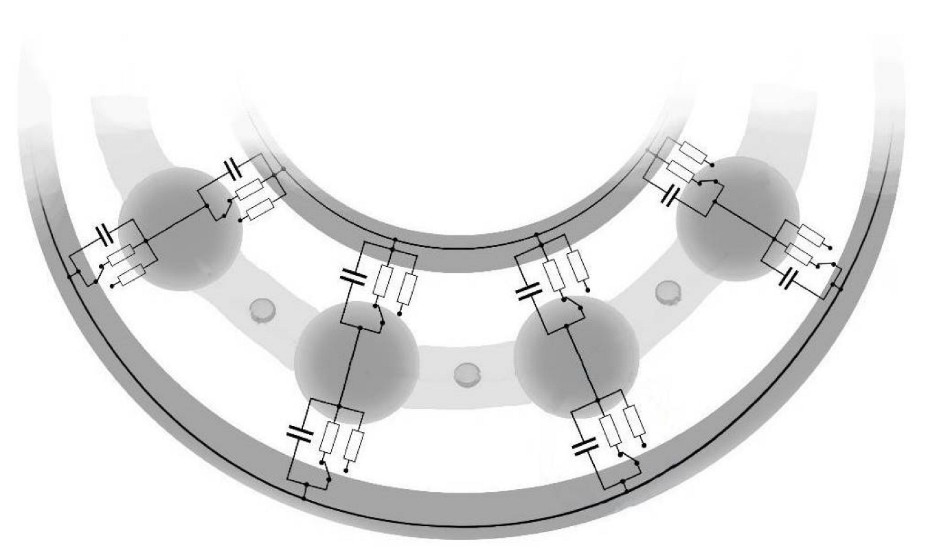
3.2.2. Impedance
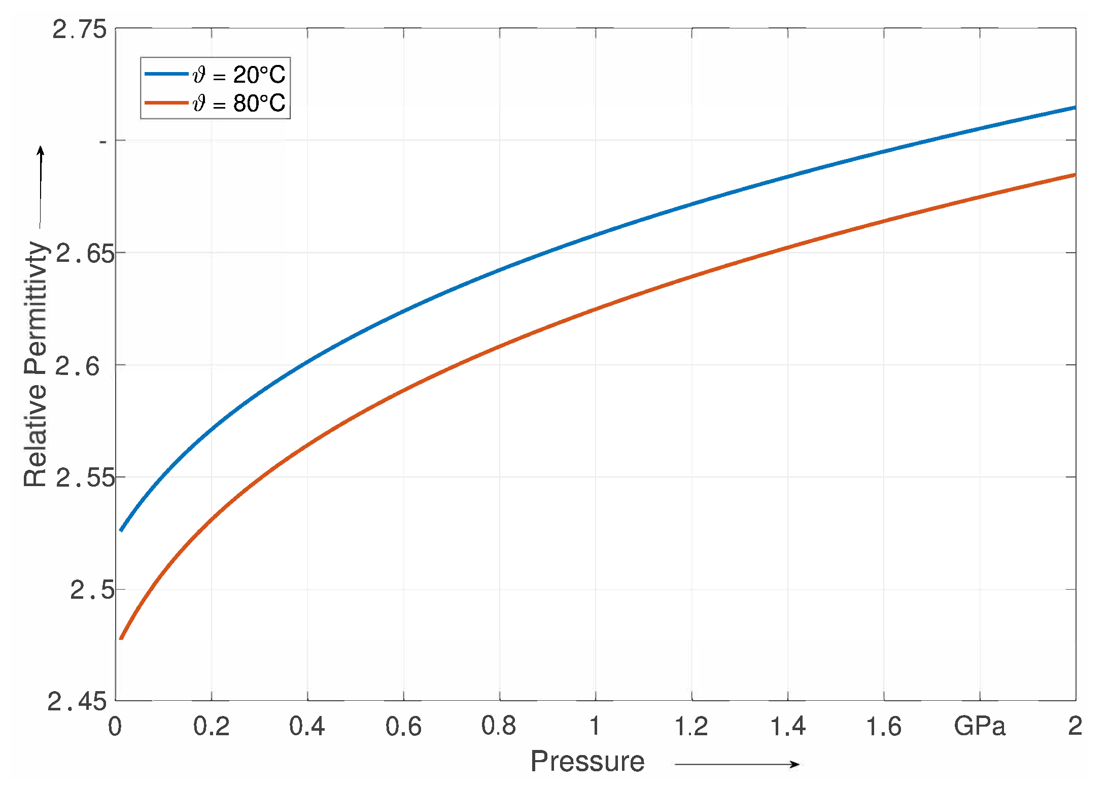
3.2.3. Electrical Properties of Lubricant
4. Sensorial Use of Rolling Bearings
4.1. Bearings as Load Sensors
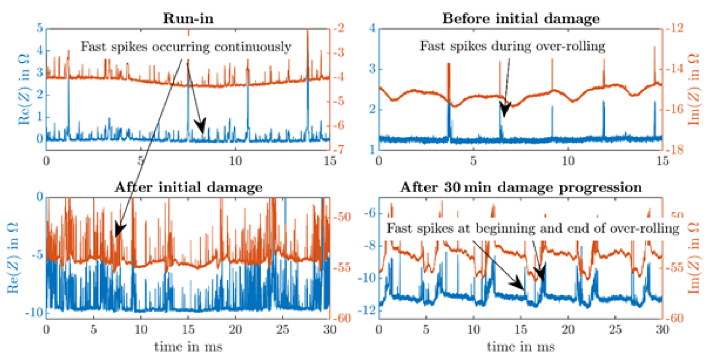
4.2. Detection of Roller Bearing Damage by Impedance Measurement
5. Conclusions
6. Outlook
Author Contributions
Funding
Institutional Review Board Statement
Informed Consent Statement
Data Availability Statement
Acknowledgments
Conflicts of Interest
Nomenclature
| Greek Symbols | ||
| absolute permittivity | F/m | |
| vacuum permittivity | As/Vm | |
| relative permittivity | − | |
| density | S/m | |
| specific resistance | kg/m | |
| Roman Symbols | ||
| A | area | m |
| C | capacitance | F |
| d | thickness of gap between capacitor plates | m |
| E | dielectric strength | V/m |
| f | frequency | Hz |
| bearing voltage ratio | ||
| h | film thickness | m |
| I | current | A |
| ratio between and | − | |
| ratio between and | − | |
| L | inductance | H |
| R | resistance | |
| U | voltage | V |
| Z | impedance | |
| j | imaginary unit | |
| Subscripts | ||
| 0 | reference | |
| b | bearing | |
| BVR | bearing voltage ratio | |
| c | central | |
| circ | circular | |
| CM | common mode | |
| con | contact | |
| EDM | electrical discharge machining | |
| EHL | elastohydrodynamic lubrication | |
| g | gear | |
| g, f | gear, film | |
| housing | housing | |
| ir | inner raceway | |
| or | outer raceway | |
| p | parallel | |
| R | rotor | |
| re | rolling element | |
| RS | rotor stator | |
| rs | replenishment/starvation | |
| S | stator | |
| shaft | shaft | |
| tot | total | |
| total | total bearing current path | |
| WR | winding rotor | |
| x | x-direction | |
| y | y-direction | |
| j | jth rolling element |
References
- Pittroff, H. Wälzlager im elektrischen Stromkreis: Riffelbildung infolge von Stromdurchgang. WäLzlagertechnische Sonderschriften 1968, 95, 54–61. [Google Scholar]
- Pöhlmann, A. Wälzlager in Elektrischen Lokomotiven und Diesellokomotiven; SKF Kugellagerfabriken Schweinfurt: Schweinfurt, Germany, 1959. [Google Scholar]
- Schenk, O. Korrosionsformen bei Wälzlagern. Maschinenschaden 1954, 27, 151–156. [Google Scholar]
- Habibullah, M.; Lu, D.D.; Xiao, D.; Rahman, M.F. Finite-State Predictive Torque Control of Induction Motor Supplied From a Three-Level NPC Voltage Source Inverter. IEEE Trans. Power Electron. 2017, 32, 479–489. [Google Scholar] [CrossRef]
- Hausberg, V. Elektrische Lagerbeanspruchung Umrichtergespeister Induktionsmaschinen. Ph.D. Thesis, Leibniz Universität Hannover, Hannover, Germany, 2001. [Google Scholar]
- Plazenet, T.; Boileau, T.; Caironi, C.C.; Nahid-Mobarakeh, B. Influencing Parameters on Discharge Bearing Currents in Inverter-Fed Induction Motors. IEEE Trans. Energy Convers. 2021, 36, 940–949. [Google Scholar] [CrossRef]
- Peta, K.; Bartkowiak, T.; Galek, P.; Mendak, M. Contact Angle Analysis of Surface Topographies Created by Electric Discharge Machining. Tribol. Inter. 2021, 107–139. [Google Scholar] [CrossRef]
- Loos, J.; Bergmann, I.; Goss, M. Influence of High Electrical Currents on WEC Formation in Rolling Bearings. Tribol. Trans. 2021, 64, 708–720. [Google Scholar] [CrossRef]
- von Jouanne, A.; Collin, R.; Stephens, M.; Miao, Y.; Thayil, B.; Li, C.; Agamloh, E.; Yokochi, A. Motor Bearing Current Characterization in SiC- Based Variable Frequency Drive Applications. In Proceedings of the 2020 IEEE Energy Conversion Congress and Exposition (ECCE), Detroit, MI, USA, 11–15 October 2020; pp. 2718–2725. [Google Scholar] [CrossRef]
- He, F.; Xie, G.; Luo, J. Electrical Bearing Failures in Electric Vehicles. Friction 2020, 8, 4–28. [Google Scholar] [CrossRef] [Green Version]
- Prashad, H. Theoretical Analysis of Capacitive Effect of Roller Bearings on Repeated Starts and Stops of a Machine Operating Under the Influence of Shaft Voltages. J. Tribol. 1992, 114, 818–822. [Google Scholar] [CrossRef]
- Furtmann, A.; Tischmacher, H.; Poll, G. Extended HF Equivalent Model of a Drive Train. In Proceedings of the 2016 XXII International Conference on Electrical Machines (ICEM), Piscataway, NJ, USA, 4–7 September 2016; pp. 2244–2250. [Google Scholar] [CrossRef]
- Furtmann, A.; Poll, G. Electrical Stress and Parasitic Currents in Machine Elements of Drive Trains with Voltage Source Inverters. In Proceedings of the International Conference on Gears, Garching, Germany, 13–15 September 2017. [Google Scholar]
- Martin, G.; Becker, F.M.; Kirchner, E. A Novel Method for Diagnosing Rolling Bearing Surface Damage by Electric Impedance Analysis. Tribol. Int. 2022, 170, 107503. [Google Scholar] [CrossRef]
- Gould, B.; Demas, N.; Erck, R.; Lorenzo-Martin, M.C.; Ajayi, O.; Greco, A. The effect of electrical current on premature failures and microstructural degradation in bearing steel. Int. J. Fatigue 2021, 145, 106078. [Google Scholar] [CrossRef]
- Preisinger, G. Cause and Effect of Bearing Currents in Frequency Converter Driven Electrical Motors: Investigations of Electrical Properties of Rolling Bearings. Ph.D. Thesis, TU Wien, Vienna, Austria, 2002. [Google Scholar]
- Furtmann, A. Elektrische Belastung von Maschinenelementen im Antriebsstrang. Ph.D. Thesis, Leibniz Universität Hannover, Hannover, Germany, 2017. [Google Scholar]
- Kriese, M.; Wittek, E.; Gattermann, S.; Tischmacher, H.; Poll, G.; Ponick, B. Influence of bearing currents on the bearing lifetime for converter driven machines. In Proceedings of the Influence of Bearing Currents on the Bearing Lifetime for Converter Driven Machines, Marseille, France, 2–5 September 2012; pp. 1735–1739. [Google Scholar] [CrossRef]
- Tischmacher, H.; Gattermann, S. Bearing currents in converter operation. In Proceedings of the XIX IEEE International Conference on Electrical Machines-ICEM 2010, Rome, Italy, 6–8 September 2010; pp. 1–8. [Google Scholar] [CrossRef]
- Tischmacher, H. Systemanalysen zur Elektrischen Belastung von Wälzlagern bei Umrichtergespeisten Elektromotoren. Ph.D. Thesis, Leibniz Universität Hannover, Hannover, Germany, 2017. [Google Scholar]
- Tischmacher, H.; Gattermann, S. Multiple Signature Analysis for the Detection of Bearing Currents and the Assessment of the Resulting Bearing Wear. In Proceedings of the International Symposium on Power Electronics Power Electronics Electrical Drives, Automation and Motion, Sorrento, Italy, 20–22 June 2012; pp. 1354–1359. [Google Scholar] [CrossRef]
- Gutiérrez Guzmán, F.; Özel, M.O.; Pinard, P. Risse auf Lagerringen-707 II; Forschungsvereinigung Antriebstechnik e.V.: Frankfurt am Main, Germany, 2017; p. 1229. [Google Scholar]
- Schneider, V.; Stockbrügger, J.O. Stromdurchgang am Wälzlager-863 I; Forschungsvereinigung Antriebstechnik e.V.: Frankfurt am Main, Germany, 2022; p. 1501. [Google Scholar]
- Iso, K.; Yokouchi, A.; Takemura, H. Research Work for Clarifying the Mechanism of White Structure Flaking and Extending the Life of Bearings; SAE Technical Paper 2005-01-1868; SAE Technical Paper: Warrendale, PA, USA, 2005. [Google Scholar] [CrossRef]
- Mütze, A. Bearing Currents in Inverter-Fed AC-Motors. Ph.D. Thesis, Technische Universität Darmstadt, Darmstadt, Germany, 2004. [Google Scholar]
- Muetze, A.; Binder, A.; Vogel, H.; Hering, J. Experimental evaluation of the endangerment of ball bearings due to inverter-induced bearing currents. In Proceedings of the Conference Record of the 2004 IEEE Industry Applications Conference, 39th IAS Annual Meeting, Seattle, WA, USA, 3–7 October 2004; pp. 1989–1995. [Google Scholar] [CrossRef]
- Muetze, A.; Binder, A.; Vogel, H.; Hering, J. What can bearings bear? IEEE Ind. Appl. Mag. 2006, 12, 57–64. [Google Scholar] [CrossRef]
- Graf, S.; Sauer, B. (Eds.) Surface Mutation of the Bearing Raceway during Electrical Current Passage in Mixed Friction Operation; VDMA: Frankfurt am Main, Germany, 2020. [Google Scholar]
- Plazenet, T.; Boileau, T. Overview of Bearing White Etching Cracks due to Electrical Currents. In Proceedings of the 2021 IEEE 13th International Symposium on Diagnostics for Electrical Machines, Power Electronics and Drives (SDEMPED), Dallas, TX, USA, 22–25 August 2021; pp. 440–446. [Google Scholar] [CrossRef]
- Muetze, A.; Binder, A. Generation of High-Frequency Common Mode Currents in Machines of Inverter-Based Drive Systems. In Proceedings of the 2005 European Conference on Power Electronics and Applications, Dresden, Germany, 11–14 September 2005. [Google Scholar] [CrossRef]
- Kriese, M.; Wittek, E.; Gattermann, S.; Tischmacher, H.; Poll, G.; Ponick, B. Prediction of Motor Bearing Currents for Converter Operation. In Proceedings of the XIX International Conference on Electrical Machines—ICEM, Rome, Italy, 6–8 September 2010; pp. 1–6. [Google Scholar] [CrossRef]
- Magdun, O. Calculation of High-Frequency Current Distribution in Inverter-Fed Electrical Machines. Ph.D. Thesis, Darmstadt University of Technology, Darmstadt, Germany, 2013. [Google Scholar]
- Huan, J.; Li, S.; Xia, Z.; Wang, Y.; Wang, W.; Shi, G. Experimental Study on Electric Corrosion Damage of Bearing and Solution. Proc. Inst. Mech. Eng. Part C J. Mech. Eng. Sci. 2022. [Google Scholar] [CrossRef]
- Busse, D.; Erdman, J.; Kerkman, R.; Schlegel, D.; Skibinski, G. System Electrical Parameters and Their Effects on Bearing Currents. IEEE Trans. Ind. Appl. 1997, 33, 577–584. [Google Scholar] [CrossRef]
- Boglietti, A.; Carpaneto, E. An Accurate Induction Motor High- Frequency Model for Electromagnetic Compatibility Analysis. Electr. Power Components Syst. 2001, 29, 191–210. [Google Scholar] [CrossRef]
- Grandi, G.; Casadei, D.; Reggiani, U. Common- and Differential-Mode HF Current Components in AC Motors Supplied by Voltage Source Inverters. IEEE Trans. Power Electron. 2004, 19, 16–24. [Google Scholar] [CrossRef]
- Helmholdt-Zhu, T.; Knebusch, B.; Borcherding, H. High-Frequency Models for the Prediction of Transient Effects in Motor Windings under Fast Rising Impulse Voltages. In Proceedings of the PCIM Europe Digital Days 2020, International Exhibition and Conference for Power Electronics, Intelligent Motion, Renewable Energy and Energy Management, Nuremburg, Germany, 7–8 July 2020; pp. 673–680. [Google Scholar]
- Gersem, H.D.; Muetze, A. Finite-Element Supported Transmission- Line Models for Calculating High-Frequency Effects in Machine Windings. IEEE Trans. Magn. 2012, 28, 787–791. [Google Scholar] [CrossRef]
- Radja, N.; Rachek, M.; Larbi, S.N. Improved RLMC-Circuit HF-Dependent Parameters Using FE-EM Computation Dedicated to Predict Fast Transient Voltage Along Insulated Windings. IEEE Trans. Electromagn. Compat. 2019, 61, 301–308. [Google Scholar] [CrossRef]
- Gersem, H.D.; Weiland, T.; Henze, O.; Binder, A. Eddy-current formulation for constructing transmission-line models for machine windings. Eur. Phys. J. Appl. Phys. 2010, 49, 1–7. [Google Scholar] [CrossRef]
- Jorks, H.V.; Gjonaj, E.; Weiland, T.; Magdun, O.N. Three-dimensional simulations of an induction motor including eddy current effects in core laminations. IET Sci. Meas. Technol. 2012, 6, 344–349. [Google Scholar] [CrossRef]
- Behrendt, C.N.; Dittmann, J.; Knebusch, B.; Ponick, B. Common-Mode Impedance Prediction of a High Frequency Hairpin Stator Winding Based on FEM and Modified Nodal Analysis. In Proceedings of the International Symposium on Power Electronics, Electrical Drives, Automation and Motion (SPEEDAM), Sorrento, Italy, 22–24 June 2022; pp. 20–26. [Google Scholar] [CrossRef]
- Stockbrügger, J.O. Analytische Bestimmung Parasitärer Kapazitäten in Elektrischen Maschinen. Ph.D. Thesis, Institutionelles Repositorium der Leibniz Universitat Hannover, Hannover, Germany, 2021. [Google Scholar] [CrossRef]
- Radnai, B.; Gemeinder, Y. FVA 650 I: Schädlicher Stromdurchgang; Forschungsvereinigung Antriebstechnik e.V.: Frankfurt am Main, Germany, 2015; Volume 1127. [Google Scholar]
- Gemeinder, Y. Lagerimpedanz und Lagerschädigung bei Stromdurchgang in Umrichtergespeisten Elektrischen Maschinen. Ph.D. Thesis, Technische Universität Darmstadt, Darmstadt, Germany, 2016. [Google Scholar]
- Hamrock, B.J.; Dowson, D. Ball Bearing Lubrication: The Elastohydrodynamics of Elliptical Contacts; Wiley: New York, NY, USA, 1981. [Google Scholar]
- Schneider, V.; Liu, H.C.; Bader, N.; Furtmann, A.; Poll, G. Empirical Formulae for the Influence of Real Film Thickness Distribution on the Capacitance of an EHL Point Contact and Application to Rolling Bearings. Tribol. Int. 2021, 154, 106714. [Google Scholar] [CrossRef]
- Bader, N.; Liu, H.; Zhang, B.B.; Poll, G. Film Thickness Measurements in EHL-Contacts Using Capacitance Measurements. In Proceedings of the Leeds-Lyon Symposium on Tribology 2019, Valpré, France, 5–10 September 2021. [Google Scholar]
- Jablonka, K.; Glovnea, R.; Bongaerts, J. Evaluation of EHD Films by Electrical Capacitance. J. Phys. Appl. Phys. 2012, 45, 385301. [Google Scholar] [CrossRef]
- Barz, M. Die Schmierfilmbildung in Fettgeschmierten Schnellaufenden Spindellagern. Ph.D. Thesis, Leibniz Universität Hannover, Hannover, Germany, 1996. [Google Scholar]
- Wittek, E.; Kriese, M.; Tischmacher, H.; Gattermann, S.; Ponick, B.; Poll, G. Capacitances and Lubricant Film Thicknesses of Motor Bearings under Different Operating Conditions. In Proceedings of the 2010 XIX IEEE International Conference on Electrical Machines, Rome, Italy, 6–8 September 2010; pp. 1–6. [Google Scholar] [CrossRef]
- Schneider, V.; Bader, N.; Liu, H.; Poll, G. Method for in Situ Film Thickness Measurement of Ball Bearings under Combined Loading Using Capacitance Measurements. Tribol. Int. 2022, 171, 107524. [Google Scholar] [CrossRef]
- Lubrecht, A. Numerical Solution of the EHL Line and Point Contact Problem Using Multigrid Techniques. Ph.D. Thesis, University of Twente, Enschede, The Netherlands, 1987. [Google Scholar]
- Venner, C.H. Multilevel Solution of the EHL Line and Point Contact Problems. Ph.D. Thesis, University of Twente, Enschede, The Netherlands, 1991. [Google Scholar]
- Tischmacher, H.; Kartashov, O. Simulation von Lichtbogenentladungen in Wälzlagern von Elektromotoren zur Interpretation von experimentellen Ergebnissen an einem Lagerversuchsstand. In Proceedings of the 32. CADFEM Users’ Meeting, Nürmberg, Germany, 4–6 June 2014. [Google Scholar]
- Jagenbrein, A. Investigations of Bearing Failures Due to Electric Current Passage. Ph.D. Thesis, Technische Universität Wien, Vienna, Austria, 2005. [Google Scholar]
- Busse, D.; Erdman, J.; Kerkman, R.; Schlegel, D.; Skibinski, G. The Effects of PWM Voltage Source Inverters on the Mechanical Performance of Rolling Bearings. Ind. Appl. IEEE Trans. 1997, 33, 567–576. [Google Scholar] [CrossRef]
- Prashad, H. Tribology in Electrical Environments; Elsevier: Amsterdam, The Netherlands, 2006. [Google Scholar]
- Zika, T. Electric Discharge Damaging in Lubricated Rolling Contacts. Ph.D. Thesis, Technische Universität Wien, Vienna, Austria, 2010. [Google Scholar]
- Tischmacher, H.; Gattermann, S. Einflussgrößen auf Lagerströme bei umrichtergespeisten Elektromotoren. VDI-Berichte 2013, 2202, 45–59. [Google Scholar]
- International Electrotechnical Commission. IEC 60156: Insulating Liquids-Determination of the Breakdown Voltage at Power Frequency-Test Method; IEC: Geneva, Switzerland, 1995. [Google Scholar]
- Wittek, E. Charakterisierung des Schmierungszustandes im Rillenkugellager mit dem Kapazitiven Messverfahren. Ph.D. Thesis, Leibniz Universität Hannover, Hannover, Germany, 2016. [Google Scholar]
- Skinner, J.F.; Cussler, E.L.; Fuoss, R.M. Pressure Dependence of Dielectric Constant and Density of Liquids. J. Phys. Chem. 1968, 72, 1057–1064. [Google Scholar] [CrossRef]
- Jackson, J.D. Classical Electrodynamics, 3rd ed.; Wiley: New York, NY, USA, 1999. [Google Scholar]
- Bondi, A.A. Physical Chemistry of Lubricating Oils; Book Division, Reinhold Pub. Corp.: New York, NY, USA, 1951. [Google Scholar]
- Schrader, R. Die Schmierfilmbildung von Additivierten Mineralölen, synthetischen Schmierfilmflüssigkeiten und Schmierfetten im elastohydrodynamischen Wälzkontakt. Ph.D. Thesis, Leibniz Universität Hannover, Hannover, Germany, 1988. [Google Scholar]
- Bode, B. Entwicklung eines Quarzviskosimeters fuer Messungen bei Hohen Druecken. Ph.D. Thesis, Technische Universität Clausthal, Clausthal-Zellerfeld, Germany, 1984. [Google Scholar]
- Bode, B. Modell zur Beschreibung des Fliessverhaltens von Flüssigkeiten unter hohem Druck. Tribol. Schmier. 1989, 35, 256–261. [Google Scholar]
- Matt, D.T.; Rauch, E. SME 4.0: The Role of Small- and Medium-Sized Enterprises in the Digital Transformation. In Industry 4.0 for SMEs: Challenges, Opportunities and Requirements; Matt, D.T., Modrák, V., Zsifkovits, H., Eds.; Springer International Publishing: Berlin/Heidelberg, Germany, 2020; pp. 3–36. [Google Scholar] [CrossRef] [Green Version]
- Martin, G.; Vogel, S.; Schirra, T.; Vorwerk-Handing, G.; Kirchner, E. Methodical Evaluation of Sensor Positions for Condition Monitoring of Gears. In Proceedings of the DS 91: Proceedings of NordDesign, Linköping, Sweden, 14–17 August 2018. [Google Scholar]
- Vorwerk-Handing, G.; Gwosch, T.; Schork, S.; Kirchner, E.; Matthiesen, S. Classification and Examples of next Generation Machine Elements. Forsch. Ingenieurwesen 2020, 84, 21–32. [Google Scholar] [CrossRef] [Green Version]
- Lewicki, W. Some Physical Aspects of Lubrication in Rolling Bearings and Gears. Ph.D. Thesis, Birbeck College, University of London, London, UK, 1955. [Google Scholar]
- Crook, A.W.; Allibone, T.E. The Lubrication of Rollers II. Film Thickness with Relation to Viscosity and Speed. Philos. Trans. R. Soc. Lond. Ser. Math. Phys. Sci. 1961, 254, 223–236. [Google Scholar] [CrossRef]
- Crook, A.W. Some Physical Aspects of Lubrication and Wear. Contemp. Phys. 1962, 3, 257–271. [Google Scholar] [CrossRef]
- Dyson, A.; Naylor, H.; Wilson, A.R. The Measurement of Oil-Film Thickness in Elastohydrodynamic Contacts. Proc. Inst. Mech. Eng. Conf. Proc. 1965, 180, 119–134. [Google Scholar] [CrossRef]
- Bader, N.; Furtmann, A.; Tischmacher, H.; Poll, G. Capacitances and Lubricant Film Thicknesses of Grease and Oil Lubricated Bearings. In Proceedings of the STLE Annual Meeting & Exhibition, Atlanta, GA, USA, 21–25 May 2017; pp. 311–314. [Google Scholar]
- Jablonka, K.; Glovnea, R.; Bongaerts, J. Quantitative Measurements of Film Thickness in a Radially Loaded Deep-Groove Ball Bearing. Tribol. Int. 2018, 119, 239–249. [Google Scholar] [CrossRef]
- Schirra, T.; Martin, G.; Puchtler, S.; Kirchner, E. Electric Impedance of Rolling Bearings—Consideration of Unloaded Rolling Elements. Tribol. Int. 2021, 158. [Google Scholar] [CrossRef]
- Schirra, T. Phänomenologische Betrachtung der sensorisch nutzbaren Effekte am Wälzlager: Einfluss unbelasteter Wälzkörper auf die elektrische Impedanz. Ph.D. Dissertation, Technische Universität Darmstadt, Darmstadt, Germany, 2020. [Google Scholar]
- Schnabel, S.; Marklund, P.; Minami, I.; Larsson, R. Monitoring of Running-in of an EHL Contact Using Contact Impedance. Tribol. Lett. 2016, 63, 35. [Google Scholar] [CrossRef] [Green Version]
- Maruyama, T.; Maeda, M.; Nakano, K. Lubrication Condition Monitoring of Practical Ball Bearings by Electrical Impedance Method. Tribol. Online 2019, 14, 327–338. [Google Scholar] [CrossRef] [Green Version]
- Martin, G.; Schirra, T.; Kirchner, E. Experimental High Frequency Analysis of the Electric Impedance of Rolling Bearings. In Proceedings of the Bearing World, Würzburg, Germany, 5–6 July 2020; VDMA: Frankfurt am Main, Germany, 2020. [Google Scholar]
- Schirra, T.; Martin, G.; Vogel, S.; Kirchner, E. Ball Bearings as Sensors for Systematical Combination of Load and Failure Monitoring. In Proceedings of the DS 92: Proceedings of the DESIGN 2018 15th International Design Conference, Dubrovnik, Croatia, 21–24 May 2018; pp. 3011–3022. [Google Scholar] [CrossRef]
- Dahlke, H. Handbuch Wälzlager-Technik: Bauarten, Gestaltung, Betrieb; Springer Fachmedien: Wiesbaden, Germmany, 1994. [Google Scholar]
- GmbH, S.M.S. (Ed.) Condition Monitoring Praxis: Handbuch zur Schwingungs-Zustandsüberwachung von Maschinen und Anlagen, 1st ed.; Vereinigte Fachverlage GmbH: Mainz, Germany, 2019. [Google Scholar]
- Schiffler, A. Steuerungsintegrierte Prozessüberwachung bei der Zerspanung mit Motorspindeln; Schriftenreihe des PTW: “Innovation Fertigungstechnik”; Shaker: Aachen, Germany, 2011. [Google Scholar]
- Van Hecke, B.; Yoon, J.; He, D. Low Speed Bearing Fault Diagnosis Using Acoustic Emission Sensors. Appl. Acoust. 2016, 105, 35–44. [Google Scholar] [CrossRef]
- Renaudin, L.; Bonnardot, F.; Musy, O.; Doray, J.; Rémond, D. Natural Roller Bearing Fault Detection by Angular Measurement of True Instantaneous Angular Speed. Mech. Syst. Signal Process. 2010, 24, 1998–2011. [Google Scholar] [CrossRef] [Green Version]
- Kirchner, E.; Martin, G.; Vogel, S. Sensor Integrating Machine Elements—Key to In-Situ Measurements in Mechanical Engineering. In Proceedings of the 23rd International Seminar on High Technology, Piracicaba, Brazil, 4 October 2018. [Google Scholar]
- Martin, G. Die Wälzlagerimpedanz als Werkzeug zur Untersuchung von Oberflächenabweichungen in Wälzlagern. Ph.D. Thesis, Technische Universität Darmstadt, Darmstadt, Germany, 2021. [Google Scholar]


| Source | Electrical Stressing | Bearing Type | Observed Damage Pattern |
|---|---|---|---|
| [25,26,27] | A/mm kHz | 6308, 6309, 6209 | Single Frosting, Frosting, Fluting, Lubricant degradation |
| [28] | (AC) at 1.12–2.3 V, Hz | 6326, NU230, NU326 | Fluting |
| [18] | 450 mio. EDM discharges >1 A, Temperature 30 °C, 28 days; 900 mio. EDM discharges > 1 A, Temperature 80 °C, 63 days | Frosting Fluting | |
| [28] | A/mm Hz, kHz | four-ball apparatus | Frosting |
| [29] | 5–6, 40 A , 25 A 6–15, up to 200 A | 6203, NU207 | Flaking WEC |
| [22] | 0.01–0.59 A/mm DC 0.1–0.75 A/mm DC | NU206four-disc apparatus | WEC, Frosting WEC |
| [15] | 0–750 mA DC | Micro Pitting Test rig (MPR) | no WEC: 0–25 mA WEC: 75–250 mA Signs of fluting: mA |
| [8] | A/mm 0.2–3.9 A/mm | NU207 6203 | WEC WEC, Frosting |
Publisher’s Note: MDPI stays neutral with regard to jurisdictional claims in published maps and institutional affiliations. |
© 2022 by the authors. Licensee MDPI, Basel, Switzerland. This article is an open access article distributed under the terms and conditions of the Creative Commons Attribution (CC BY) license (https://creativecommons.org/licenses/by/4.0/).
Share and Cite
Schneider, V.; Behrendt, C.; Höltje, P.; Cornel, D.; Becker-Dombrowsky, F.M.; Puchtler, S.; Gutiérrez Guzmán, F.; Ponick, B.; Jacobs, G.; Kirchner, E. Electrical Bearing Damage, A Problem in the Nano- and Macro-Range. Lubricants 2022, 10, 194. https://doi.org/10.3390/lubricants10080194
Schneider V, Behrendt C, Höltje P, Cornel D, Becker-Dombrowsky FM, Puchtler S, Gutiérrez Guzmán F, Ponick B, Jacobs G, Kirchner E. Electrical Bearing Damage, A Problem in the Nano- and Macro-Range. Lubricants. 2022; 10(8):194. https://doi.org/10.3390/lubricants10080194
Chicago/Turabian StyleSchneider, Volker, Cara Behrendt, Pauline Höltje, Daniel Cornel, Florian Michael Becker-Dombrowsky, Steffen Puchtler, Francisco Gutiérrez Guzmán, Bernd Ponick, Georg Jacobs, and Eckhard Kirchner. 2022. "Electrical Bearing Damage, A Problem in the Nano- and Macro-Range" Lubricants 10, no. 8: 194. https://doi.org/10.3390/lubricants10080194
APA StyleSchneider, V., Behrendt, C., Höltje, P., Cornel, D., Becker-Dombrowsky, F. M., Puchtler, S., Gutiérrez Guzmán, F., Ponick, B., Jacobs, G., & Kirchner, E. (2022). Electrical Bearing Damage, A Problem in the Nano- and Macro-Range. Lubricants, 10(8), 194. https://doi.org/10.3390/lubricants10080194