1. Introduction
As Earth’s closest neighbor in the solar system, the Moon is regarded as a primary target for human space exploration due to its inherent environmental advantages and abundant mineral resources. At present, humanity’s exploration of the Moon remains at an early stage, and our understanding of the lunar environment is still limited. Moreover, the current exploration approaches are no longer sufficient to meet diversified requirements of future lunar development [
1]. In order to enable sustained and in-depth human exploration of solar system planets, and in alignment with space strategies that emphasize enhanced international cooperation, the National Aeronautics and Space Administration (NASA) plans to construct a crewed outpost on the Moon by 2030 [
2]. Building a lunar base necessitates the integration of critical enabling technologies spanning various domains, including propulsion systems, in-situ resource utilization (ISRU), and energy supply. Among these, energy provision serves as the core condition for ensuring the stable functioning of the lunar base and represents a fundamental requirement at every stage of its development [
3].
Energy supply refers to the technological means by which various forms of energy are converted into electrical power through appropriate conversion systems for use in relevant equipment. It has a long-standing historical foundation in space applications and is expected to serve as a core technology in the construction of lunar bases [
4]. Following the successful launch of Sputnik 1—the first artificial satellite—by the Union of Soviet Socialist Republics (USSR) in 1957, humanity has been exploring ways to achieve sustained energy supply in space. During this period, the United States (US) Navy’s Vanguard 1 satellite was equipped with solar panels, making it the first space probe to utilize solar power generation technology [
5]. In 1961, the US Navy launched the navigation satellite Transit 4A, which was equipped with a Radioisotope Thermoelectric Generator (RTG) known as SNAP-3B. This marked the first use of nuclear energy in space and represented the initial application of thermal power generation technology in extraterrestrial environments [
6]. Furthermore, the Soviet satellite “Sputnik 1” was equipped with silver-zinc chemical batteries to power its radio transmitter and temperature control system, whereas in NASA’s Apollo 7 mission, fuel cell technology was used for the first time to provide both electrical power and potable water for the spacecraft cabin [
7]. With advancements in science and technology, the range of energy sources available for space missions has continued to expand, and power generation technologies have become increasingly diversified.
At present, humanity has successfully implemented various types of energy supply schemes on the Moon. The available energy sources on the lunar surface are generally classified into four major categories: solar energy, thermal energy, nuclear energy, and chemical batteries. Solar energy supply primarily relies on the photovoltaic effect of solar panels, converting incident solar radiation into electrical energy [
8]. NASA’s Surveyor 1 was the first lunar probe to utilize solar power technology on the Moon. In current lunar exploration missions, such as China’s Chang’e Program and NASA’s Artemis Program, solar energy remains the primary mode of power supply [
9]. Thermal energy supply primarily involves the use of thermodynamic cycle engines or the physical properties of specific materials to convert heat into electrical energy. Due to current technological limitations and efficiency constraints, power systems based on non-radioactive thermal sources remain in the experimental stage and have not yet been officially deployed on the Moon. However, their underlying principles have been validated through ground-based testing, and they may be applied in future lunar base construction missions. The supply of nuclear energy involves transforming the heat produced by radioactive isotope decay into electricity using devices such as RTGs or nuclear reactors. In the Apollo 12 mission, nuclear energy was applied on the lunar surface for the first time. Astronauts Alan L. Bean and Charles P. Conrad successfully deployed the RTG device designated “SNAP-27A” in the Oceanus Procellarum region of the Moon. This device utilized the decay heat of plutonium-238 (
238Pu) to continuously supply power to scientific instruments operating on the lunar surface [
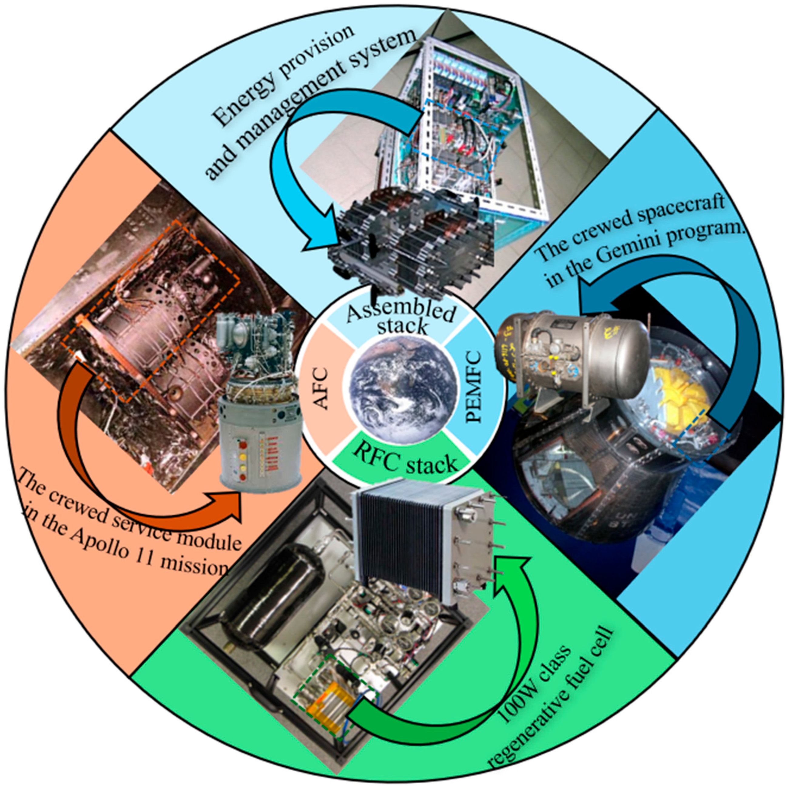
10]. Chemical power sources, such as traditional batteries and fuel cells, serve as energy supply systems that convert internally stored chemical energy into electrical power via electrochemical reactions. In the Apollo 11 mission, the spacecraft’s service module was equipped with three sets of alkaline fuel cells, each with a power output of approximately 1.5 kilowatts, providing both electrical power and water for the mission. In the Apollo 15 mission and subsequent missions, nickel–hydrogen batteries were used to supply power to lunar rovers and other scientific instruments [
11]. These developments reflect the increasing maturity of technologies used to generate electrical power from various energy sources on the Moon.
To achieve uninterrupted energy supply on the Moon, a series of environmental challenges must be addressed. Although the aforementioned energy supply technologies have been widely implemented on Earth and have undergone years of development, leading to increasingly mature solutions, their adaptation to the lunar environment remains a complex endeavor. However, the Moon’s environment is characterized by extreme temperature variations between day and night, the absence of an atmosphere, prolonged diurnal cycles, and high adherence of surface regolith. As a result, existing terrestrial energy supply technologies cannot be directly applied to the lunar surface [
12]. For instance, during the lunar night, which lasts approximately 14 Earth days, solar power systems cannot produce electrical power through the direct conversion of solar radiation. In addition, the extreme temperature variations between lunar daytime and nighttime induce thermal expansion, contraction, and material degradation in thermoelectric components. This not only reduces the efficiency of thermal-to-electric conversion but also shortens the operational lifespan of the power generation systems [
13]. The electrically charged fine lunar regolith particles tend to adhere to the surfaces of nuclear devices, potentially clogging heat dissipation vents. Such blockages diminish the thermal gradient across the hot and cold junctions of thermoelectric converters, thereby lowering their thermal-to-electric conversion efficiency [
14]. Due to the lack of a lunar atmosphere, devices on the Moon are exposed to intense radiation, which can damage the internal structure of batteries and hasten the deterioration of proton exchange membranes in fuel cells. This degradation ultimately leads to the failure of both energy storage and power supply functions [
15]. The application of a single energy supply technology on the Moon is unable to yield optimal results. To achieve sustained power delivery for future lunar bases, it is advisable to consider an integrated approach that combines multiple types of energy supply technologies.
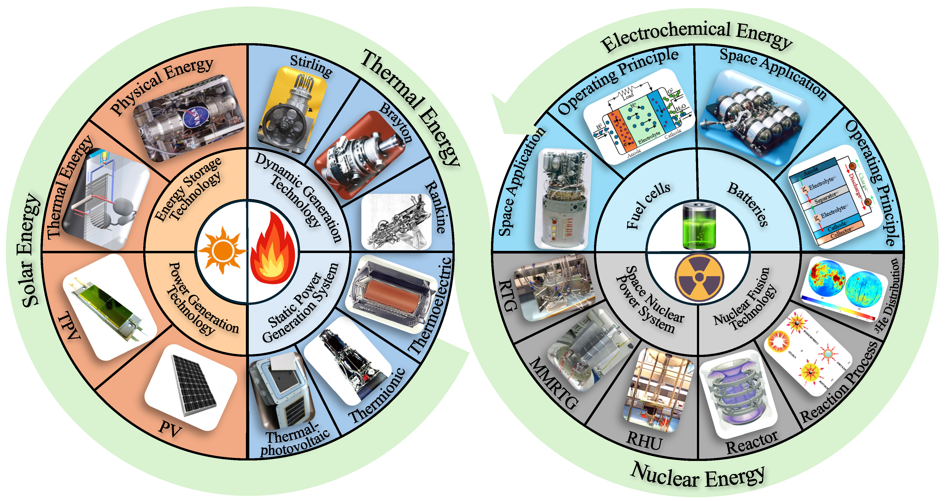
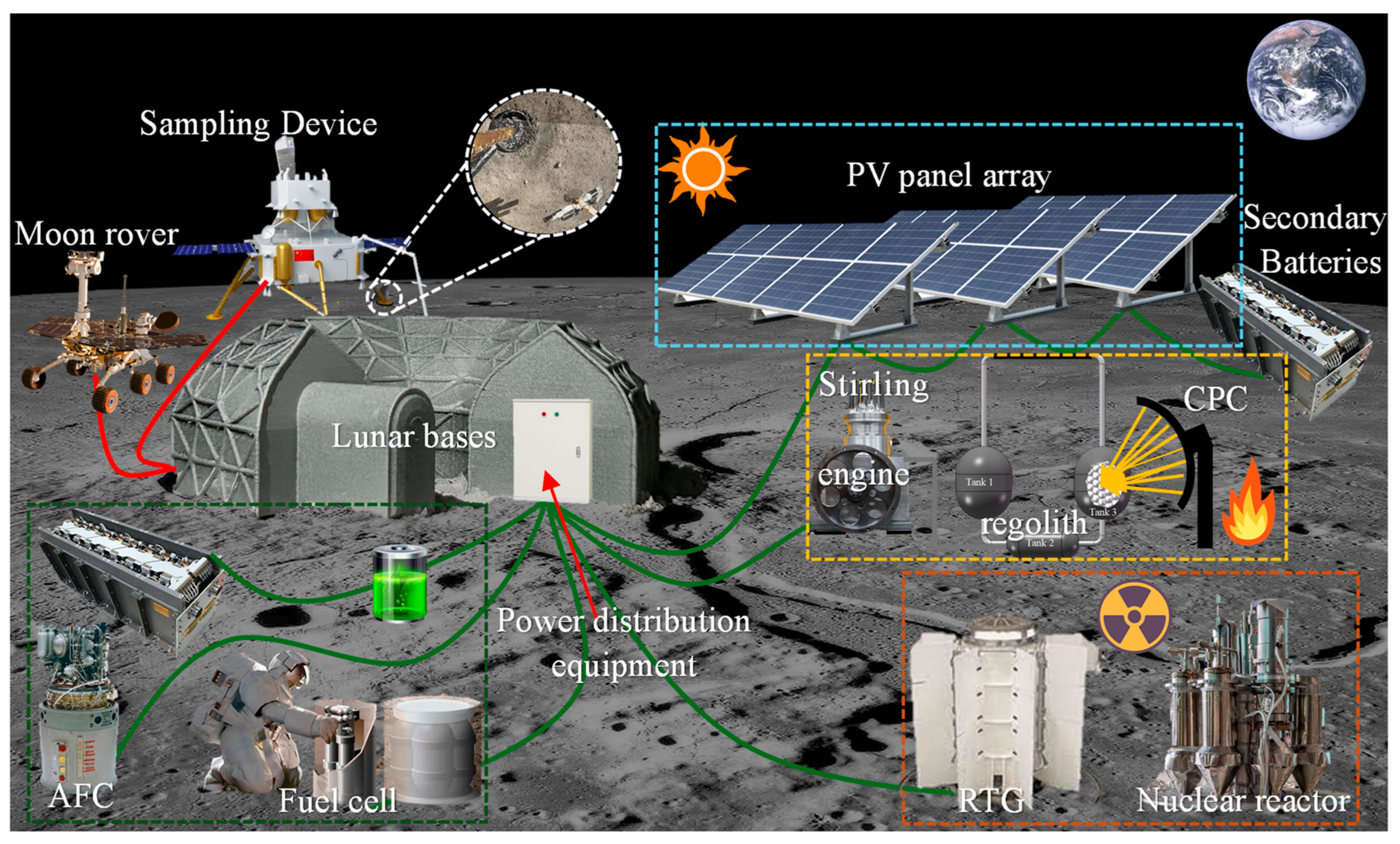
The first section of this paper provides an overview of space-based energy supply technologies, including the significance of energy supply, its historical background, the energy supply technologies currently implemented on the Moon, and the environmental challenges presently faced. The subsequent sections will provide an in-depth discussion of four types of energy supply methods: solar energy, thermal energy, nuclear energy, and chemical batteries. An overview of the content is shown in
Figure 1.
Section 2 provides an overview of solar power generation and energy storage technologies for space applications, along with strategies to improve the efficiency of solar energy conversion.
Section 3 introduces dynamic thermal power generation technologies and static thermal power systems used in space, along with a comparative evaluation of their performance.
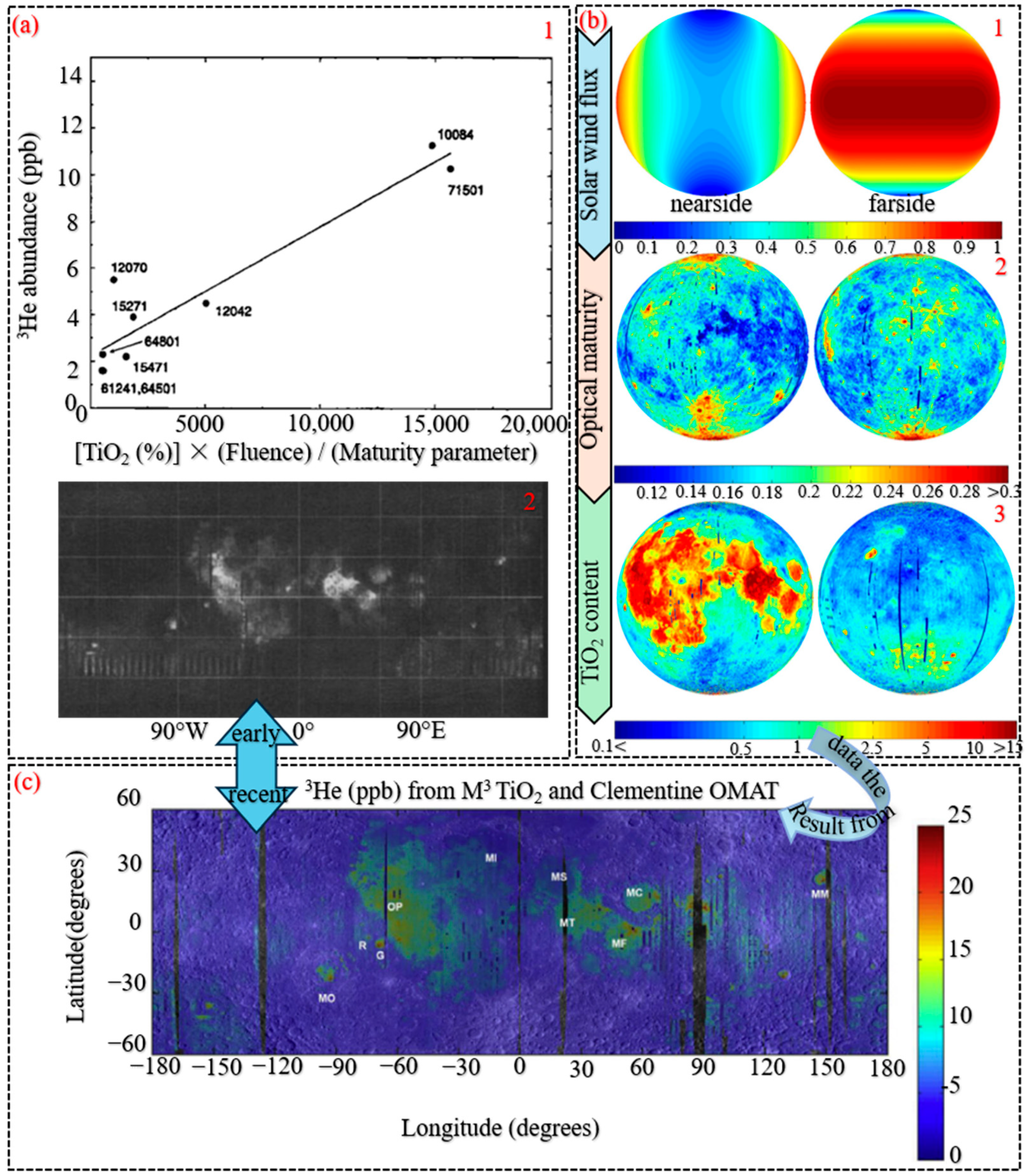
Section 4 reviews the historical applications of nuclear power systems in space, presents a brief discussion of the technical principles of nuclear fusion, and analyzes the feasibility of
3He fusion technology on the Moon.
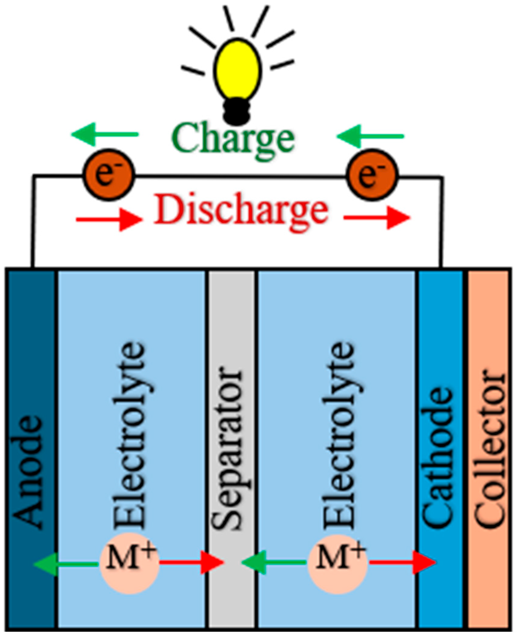
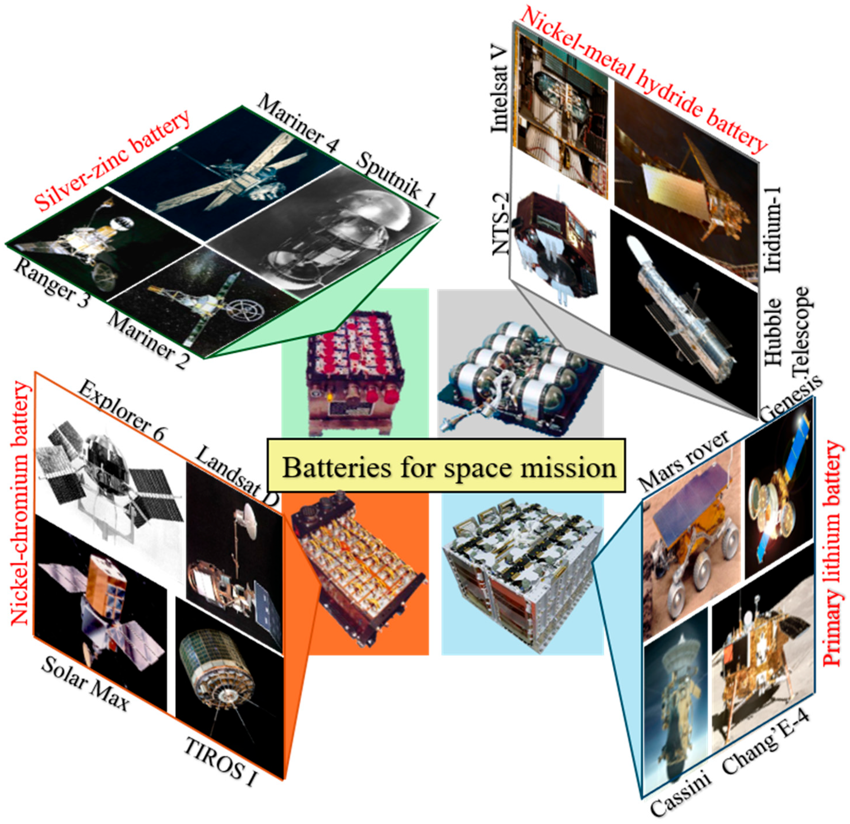
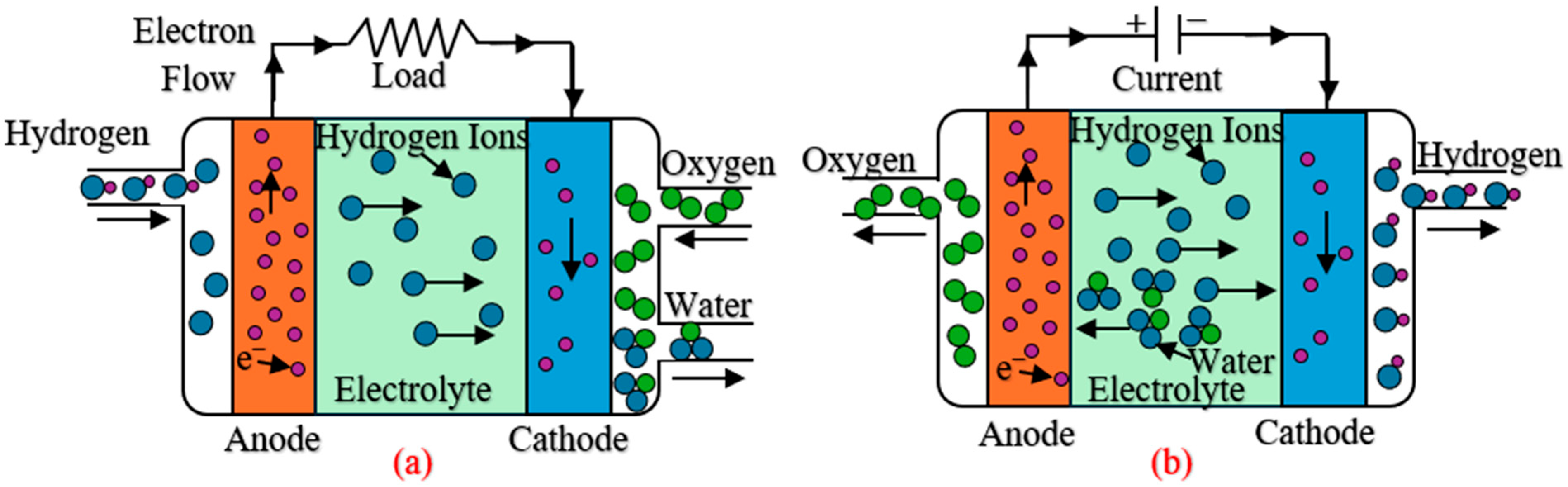
Section 5 outlines the working principles of batteries and fuel cells and summarizes their respective applications in space missions. Finally, the technical challenges associated with space-based energy supply are briefly analyzed and summarized, aiming to offer constructive guidance for advancing more robust and efficient energy supply systems in future space applications.
2. Solar Power Generation and Energy Storage Technologies
Solar energy originates from the nuclear fusion processes taking place in the core region of the Sun. Hydrogen nuclei are transformed into helium nuclei through the proton-proton chain reaction, releasing an enormous amount of energy. This energy is transported toward the Sun’s surface via mechanisms including radiative transfer and convection, and is then radiated into space as electromagnetic waves, ultimately providing energy to various celestial bodies within the solar system [
16]. Solar energy supplies the essential energy that sustains life on Earth and serves as the primary source of Earth’s temperature. It drives Earth’s atmospheric motions, water cycle, and biological activities. Unlike Earth, the Moon is devoid of an atmosphere and cloud cover, resulting in no scattering or absorption of solar radiation [
17]. Consequently, solar energy on the Moon exhibits advantages such as high radiation intensity and the absence of atmospheric interference.
2.1. Solar Power Generation Technologies
Based on the Moon’s unique environmental conditions, in order to effectively harness solar energy on the Moon, two power generation technologies can be adopted: Solar Photovoltaic (PV) power generation and Solar Thermophotovoltaic (STPV) power generation. The following is a brief introduction to these two technologies.
2.1.1. Solar Photovoltaic Power Generation
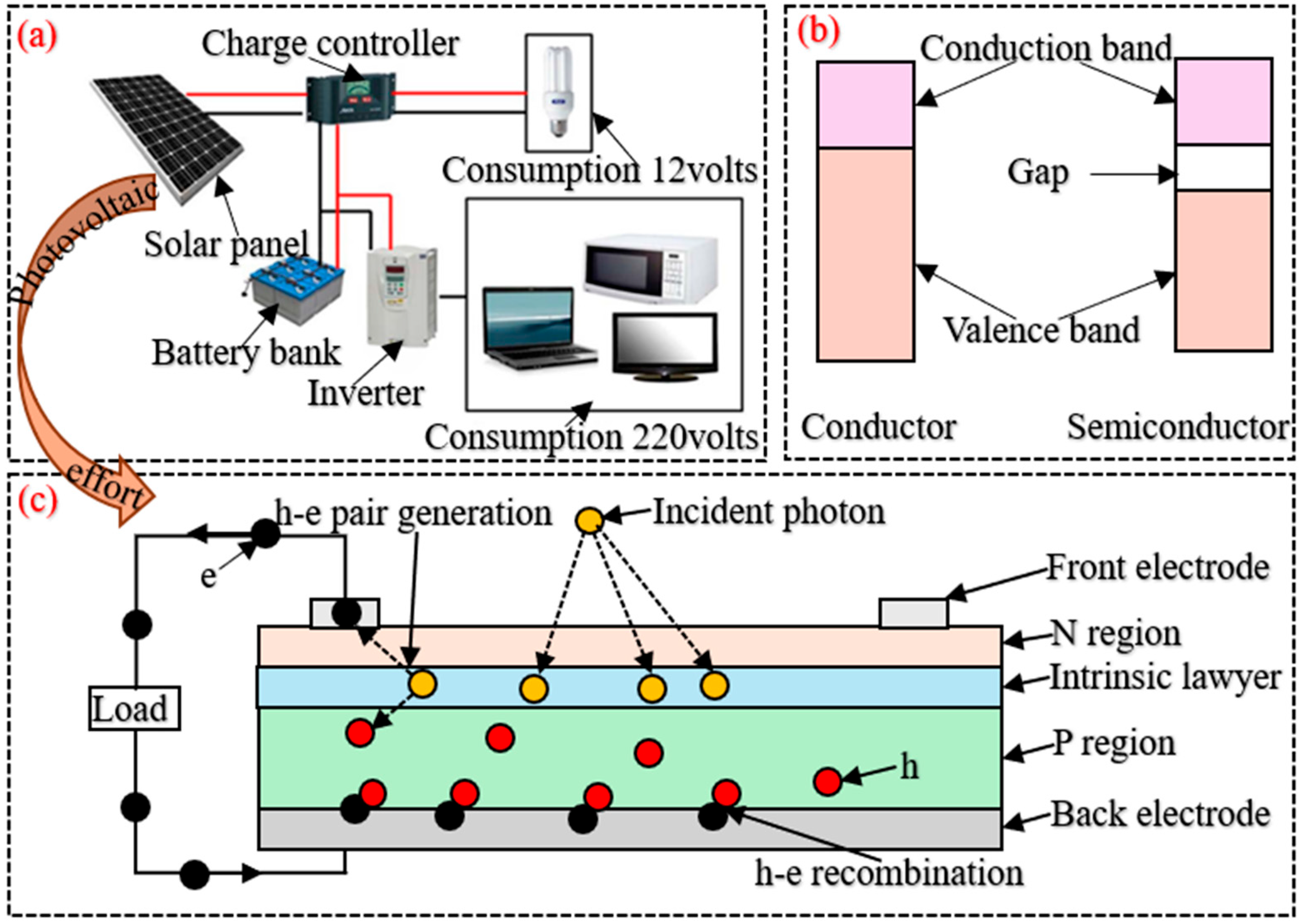
Solar PV power generation refers to a technology that harnesses the PV effect of specific materials to directly transform incident solar radiation into electrical power. A PV power generation system typically consists of solar panels, energy storage devices, charge controllers, and inverters;
Figure 2a illustrates a typical PV power generation system. Charge controllers prevent batteries from being overcharged or over-discharged, thereby extending their service life. The inverter is responsible for converting the direct current produced by the solar panels into alternating current that meets the required frequency. Energy storage devices are utilized to store surplus electrical energy generated by solar panels for deployment during periods of insufficient sunlight, such as nighttime [
18].
PV cells constitute the fundamental building blocks of solar panels, which are formed by interconnecting multiple PV cells through series and parallel configurations. A PV cell is a semiconductor device structured around a p-n junction, fabricated from various semiconductor materials. These materials possess two distinct energy bands: a valence band that permits electron existence, and a completely vacant conduction band devoid of electrons, as illustrated in
Figure 2b. Monocrystalline silicon and polycrystalline silicon dominate as the most widely utilized semiconductor materials, collectively occupying approximately 90% of the PV cell market share [
19,
20].
Figure 2c illustrates the schematic internal configuration of a PV cell, in which the N-type material constitutes the light-absorbing region, while the P-type layer is located beneath it.
The PV effect in semiconductor materials was first discovered by Becquerel [
21] in 1839, is fundamentally defined by three successive stages of energy conversion. The first stage occurs at the p-n junction, where incident photons possessing energy “
” greater than the semiconductor’s bandgap “
” are absorbed, promoting electrons from the valence band to the conduction band and resulting in the formation of electron-hole pairs [
22]. After that, under the influence of the built-in electric field, the photogenerated electrons move toward the N-type layer, while the corresponding holes are driven into the P-type region [
23]. This spatial separation of charge carriers induces electron transport through the external load, while the complementary movement of holes constitutes a closed-loop current path. Finally, upon completing work exertion on external loads, transported electrons recombine with corresponding holes at the circuit terminus, achieving full energy cycle closure [
24]. The complete reaction process is schematically illustrated in
Figure 2c. PV power generation technology can not only be applied on Earth, but it can also provide power for detection devices in space.
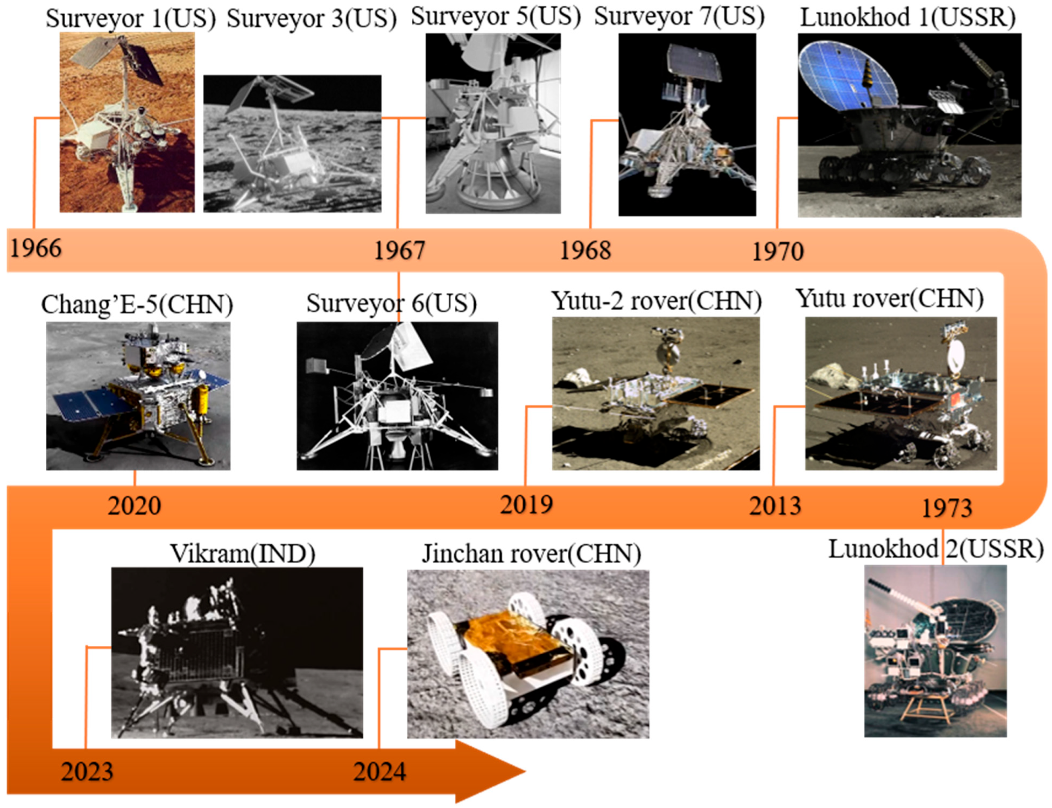
Since 1966, the US first implemented PV power generation technology in the “Surveyor Program” on the lunar surface. The program’s lunar lander—Surveyor 1, 3, 5, 6, and 7—were all equipped with solar panels that continuously provided power to detection equipment [
25]. Subsequently, the USSR conducted mobile exploration of the lunar surface environment through solar panel-equipped lunar rovers during its 1970 and 1973 lunar exploration missions [
26]. In the 21st century, China’s Chang’e Lunar Exploration Program further advanced the application of PV power generation technology on the Moon. The Yutu rover carried by Chang’e-3, the Yutu-2 rover of Chang’e-4, and the Chang’e-5 lander were all equipped with solar panels to provide electrical power [
27]. Additionally, India’s Chandrayaan-3 mission successfully achieved a soft landing on the lunar surface in 2023, with its Vikram lander and Pragyan rover both relying on solar power supply [
28]. Lunar detection devices utilizing PV power generation technology are illustrated in
Figure 3.
2.1.2. Solar Thermophotovoltaic Power Generation
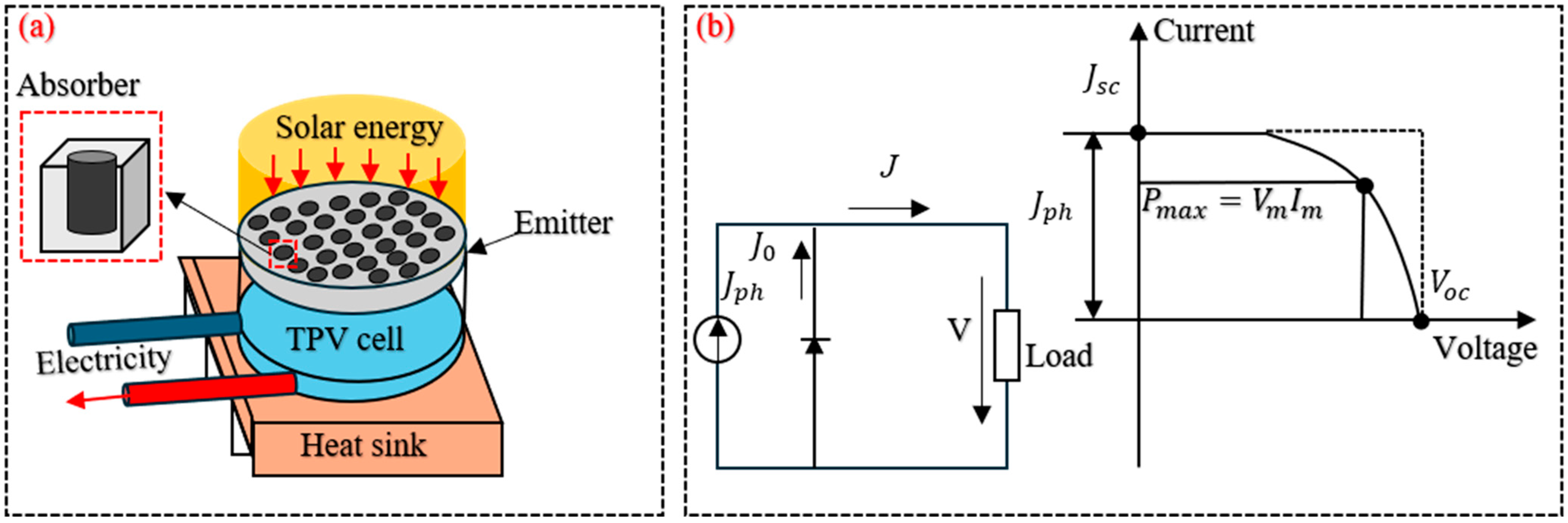
Solar Thermophotovoltaic (STPV) power generation represents a hybrid approach that integrates solar thermal energy conversion with PV electricity generation. Within STPV systems, Thermophotovoltaic (TPV) cells function by directly transforming solar radiation into electrical power [
30]. An STPV system typically consists of a solar concentrator, a thermal radiation emitter, and TPV cells [
31], as illustrated in
Figure 4a. The operational process of STPV systems comprises three sequential phases. Initially, the concentrator focuses sunlight onto the absorber to generate high temperatures for heating the emitter. The heated emitter then releases thermal energy via radiation, leveraging the selective emission properties of materials to optimize the thermal radiation spectrum, thereby matching the bandgap of TPV cells. Ultimately, the TPV cells absorb the thermal radiation emitted by the emitter and transform this radiative energy into usable electrical power [
32].
The current density
generated by the system is expressed by the Shockley diode equation as:
where
e0 refers to the elementary charge,
V denotes the voltage across the load,
k is the Boltzmann constant,
Tcell corresponds to the operating temperature of the TPV cell,
Jph represents the light-generated current density, and
J0 denotes the reverse saturation current density which quantifies the recombination level within the device [
33].
Figure 4b shows the current-voltage (I–V) curve of an ideal photovoltaic cell without consideration of parasitic resistance losses (i.e., assuming the series resistance
and the shunt resistance
), the dark current term approaches zero when the cell is short-circuited (
). It should be noted that
is a non-zero constant determined by the material properties and ambient temperature, which typically ranges from 10
−12 to 10
−9 for typical solar cells.
STPV technology remains in the experimental testing phase, constrained by technological limitations and power generation efficiency. McDonnell Douglas Corporation [
34] conducted experimental investigations on STPV systems during the mid-1990s. At the beginning of this century, the Universidad Politécnica de Madrid and Russia’s Ioffe Institute [
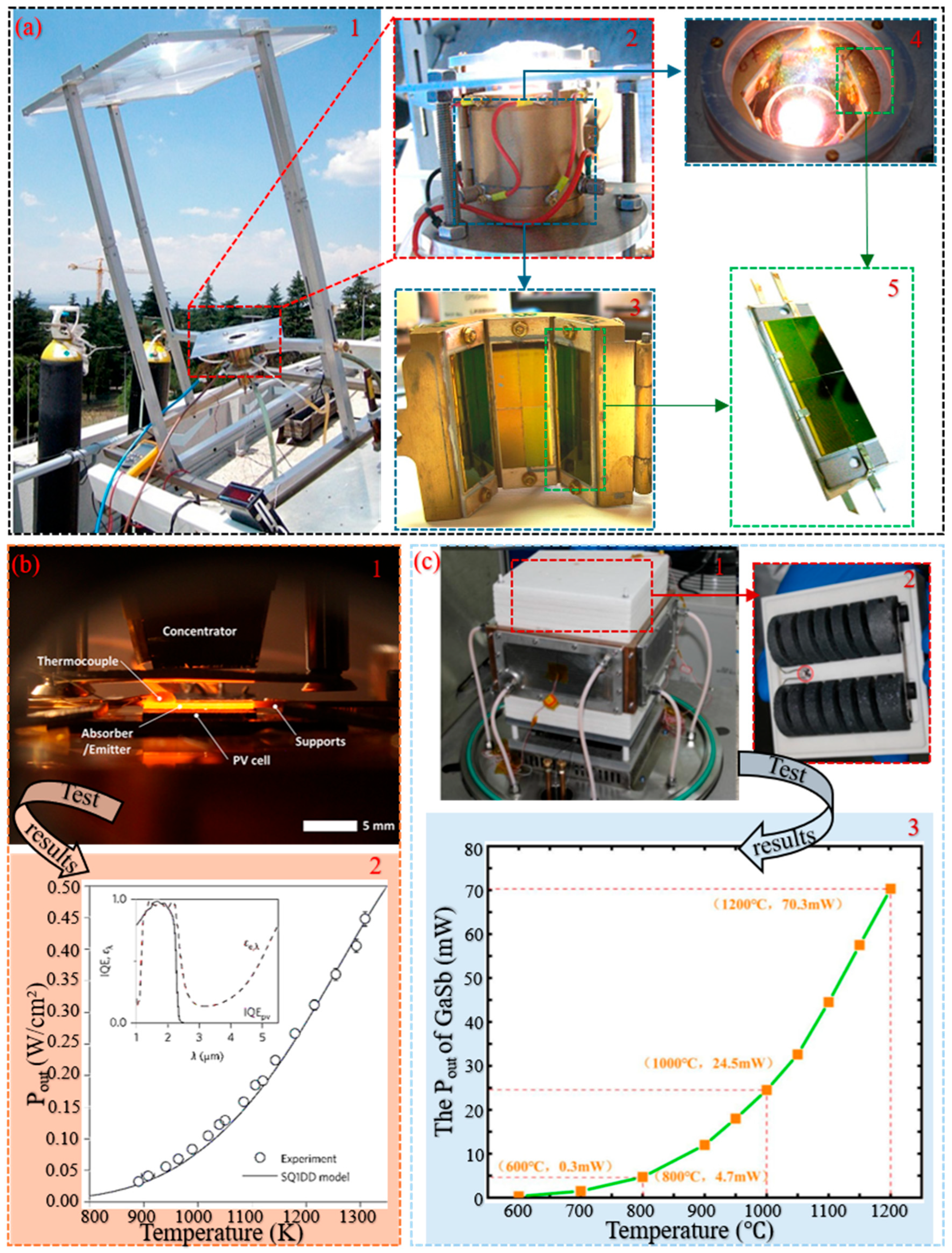
35] developed a terrestrial STPV system under the “Fullspectrum” project, as illustrated in
Figure 5a, and were the first to report that the thermal-to-electric conversion efficiency of the complete STPV system was approximately 1%. In 2014, a Massachusetts Institute of Technology team [
36] achieved a 3.2% conversion efficiency in their STPV system by employing a nanostructured selective emitter and InGaAsSb-based TPV cells (
Figure 5(b1)), with system power density profiles illustrated in
Figure 5(b2). In 2020, the European Space Agency (ESA) and the École Polytechnique Fédérale de Lausanne [
37] further enhanced the STPV system. By utilizing a tungsten-based photonic crystal emitter and employing lunar regolith as thermal insulation, the system achieved continuous power supply for 72 h. In 2024, the U.S. Air Force Research Laboratory enhanced the thermal source of the TPV system by developing a silicon carbide-based electric heating module (
Figure 5(c2)). Under this thermal source, the absolute output power of a GaSb-based TPV cell (with an active area of 148 mm
2) increased from 0.3 mW at 600 °C to 70.3 mW at 1200 °C, achieving a 233-fold overall power enhancement [
38], with results detailed in
Figure 5(c3). Recently, China Aerospace Science and Technology Corporation developed a hybrid photothermal-thermophotovoltaic power technology for lunar applications. By employing yttria-stabilized zirconia ceramics as the thermal energy storage unit, the system absorbs and stores solar energy during daylight. Rare-earth-doped emitters emit 1.5 μm infrared radiation during lunar nights, activating GaAs TPV cells to generate power [
39]. STPV technology has transitioned from experimental research to the prototype validation phase. In the future, by integrating ISRU and lightweight design, the practical application of this technology is expected to be realized.
2.2. Measures to Improve Solar Power Generation Efficiency
In order to improve the overall efficiency of the two previously discussed solar power generation approaches, several feasible optimization measures have been proposed for each technical stage of the energy conversion process. The PV cell conversion efficiency is defined as follows:
where
represents the maximum electrical power output of the PV cell,
denotes the active area exposed to illumination, and
refers the incident solar irradiance on the cell surface [
40].
2.2.1. Concentrator Photovoltaic
The use of Concentrator Photovoltaic (CPV) enhances the solar irradiance intensity received by PV cells. CPV employs technologically mature optical components to concentrate sunlight onto PV cells at higher concentration ratios. The concentration ratio
is one of the optical characteristics of the CPV, defined as the quotient of the mean irradiance received by the collector (
) and the average global normal irradiance (
):
According to the concentration ratio, CPV systems are typically classified into three levels [
41]: low concentration (1–40×), medium concentration (40–300×), high concentration (300–2000×).
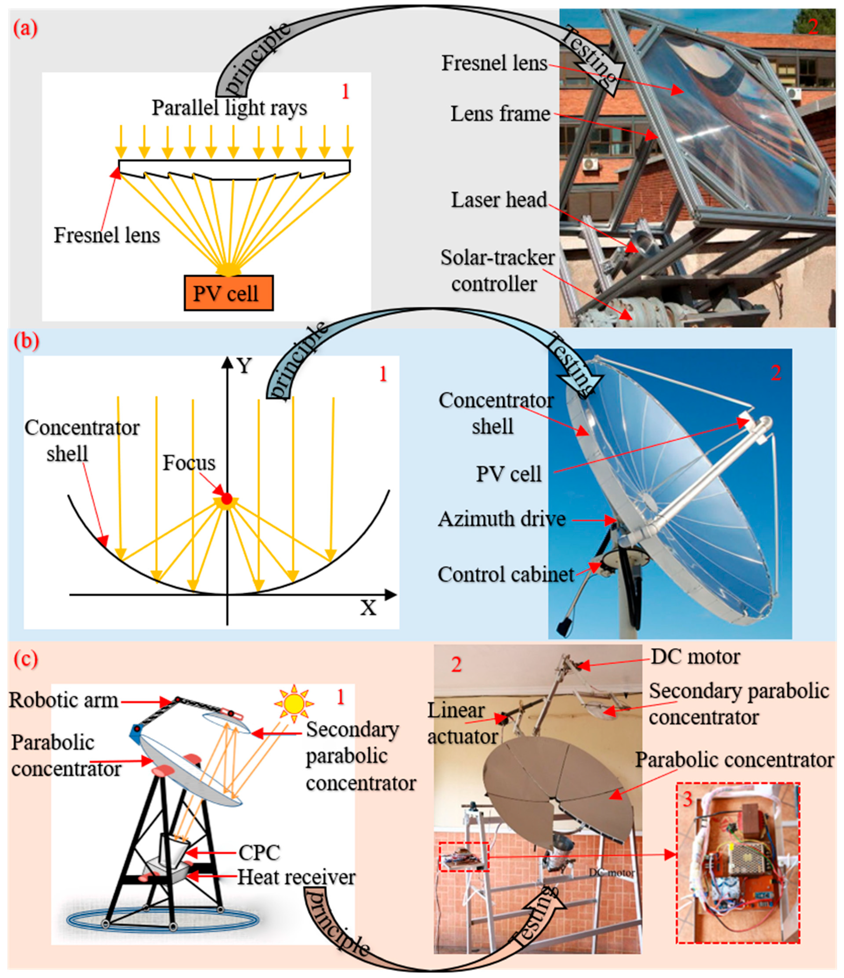
In recent years, CPVs have undergone multiple improvements and upgrades. The initial CPV was a linear Fresnel lens proposed by Kritchman et al. [
42] in 1979. Within a specific range of solar incidence angles, this lens could achieve high-concentration solar radiation at a relatively low cost. Compared to circular Fresnel lenses, the linear Fresnel lens requires smaller illuminated areas and simpler structural configurations under the same concentration ratios, as illustrated in
Figure 6a. Parabolic concentrators (
Figure 6b) employ curved mirrors to focus sunlight onto receiver tubes positioned at the focal point. Building upon this design, Omer and Infield [
43] developed a secondary concentration structure for the receiver tubes, achieving enhanced solar concentration efficiency without requiring real-time solar tracking. Furthermore, Compound Parabolic Concentrators (CPCs) are designed to focus distant light sources with defined acceptance angles. Under both direct and uniform diffuse radiation conditions, the optimal half-acceptance angle of CPCs is 26°, indicating their applicability to most concentration systems [
44], the CPC structure is illustrated in
Figure 6c. Concurrently, to validate the feasibility of CPVs in lunar environments, Hu et al. [
45] proposed a solar energy storage and power supply scheme that leverages ISRU while accounting for the unique characteristics of the lunar environment. This system employs linear Fresnel lenses to concentrate solar radiation, achieving a solar energy conversion efficiency of 19.6% and delivering an average power output of 6.5 kW during lunar nighttime. By implementing diverse CPVs in concentration systems, sunlight is focused onto smaller areas with enhanced irradiance, thereby improving photoelectric conversion efficiency while simultaneously reducing the illuminated area of PV cells [
46].
2.2.2. Gallium Antimonide-Based Thermophotovoltaic Cell
In STPV systems, the conversion efficiency from radiative thermal energy to electrical output is defined by the following expression:
where
η denotes the photoelectric conversion efficiency of the TPV cell and
represents the spectral efficiency of the emitter, defined by:
Here, E(λ) denotes the spectral distribution of blackbody radiation, while ε(λ) corresponds to the wavelength-dependent emissivity of the selective emitter [
49]. Therefore, employing appropriate selective emitters to enhance thermal transfer efficiency between the heat source and TPV cells can further improve the system’s PV conversion efficiency.
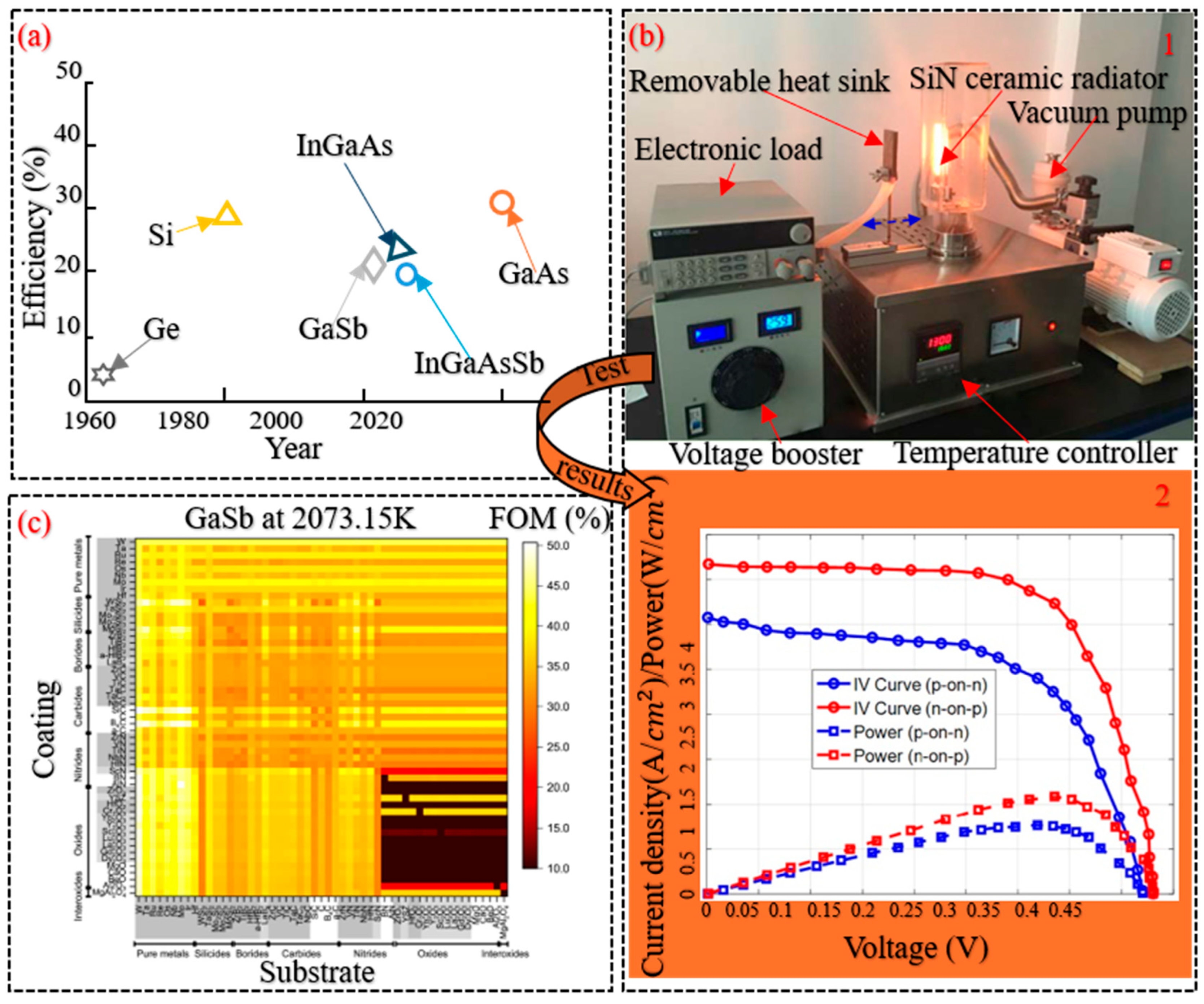
Historically, the PV conversion efficiencies of cells fabricated from various materials are illustrated in
Figure 7a. The data demonstrate that Gallium Antimonide-Based (GaSb-based) TPV cells exhibit significant developmental potential. GaSb-based TPV cells achieve quantum emission efficiencies exceeding 90% within the 1300 to 1500 K temperature range. Compared to conventional materials (Si, Ge), these cells exhibit less performance degradation at elevated operating temperatures [
50]. In 1989, Fraas et al. [
51] developed the first GaSb-based TPV cells using the zinc diffusion method. The TPV system employing this cell achieved an energy conversion efficiency of 35%. Subsequent studies found that the performance parameters of GaSb-based TPV cells are influenced by emitter depth, doping concentration, and junction configurations. Rajagopalan et al. [
52] fabricated TPV cells using single-step zinc diffusion and emitter etching techniques to determine the optimal emitter depth. Experimental measurements revealed that when the emitter depth of the fabricated cells reached approximately 0.4 µm, the output power reached its maximum value. Tang et al. [
53] investigated the impact of doping concentration on cell output power. By introducing selenium diffusion into p-doped TPV cells and depositing a SiO
2 layer on the substrate surface, under 1500 K blackbody radiation (
Figure 7(b1)), the ‘n-p’ configured cells with silicon nitride (SiN) ceramic emitters demonstrated higher quantum emission efficiency compared to conventional ‘p-n’ structures, achieving a 1.42-fold enhancement in output power density, with results presented in
Figure 7(b2). Dias et al. [
54] improved the junction structure of the cell, achieving a tandem configuration by integrating 2809 coating-substrate pairs. By altering the film thickness to tune the spectral emissivity, they ultimately demonstrated a power conversion efficiency approaching 50% (
Figure 7c), with an output power density of 10.2 W/cm
2. Furthermore, conventional planar STPV systems are susceptible to thermal losses. Rinnerbauer et al. [
55] developed a cage-type hybrid architecture STPV system, utilizing nanophotonic techniques to fabricate emitters and absorbers. This design enhances photon emission efficiency while mitigating thermal loss impacts.
2.2.3. Photovoltaic Cell Array
As previously mentioned, PV cells constitute the fundamental building blocks of solar panels. To achieve higher output voltage, panels are typically formed by connecting PV cells in series. For increased output current, this can be realized either by increasing the illuminated area of individual cells or through parallel connections of multiple cells. A PV array refers to a large-scale PV system composed of interconnected solar panels arranged in series and parallel configurations [
58].
Tian et al. [
59] developed an equivalent circuit based on the diode model of PV cells. After outdoor experimental validation (
Figure 8(a1)), this circuit was established as a generalized model for calculating electrical parameters of PV cell arrays. The correlation between the output current (
) and voltage (
) of the PV array is characterized by the following equation:
where
denotes the photo current,
and
represent the number of series-connected and parallel-connected photovoltaic modules, respectively. The variable q is the elementary charge, n is the ideality factor,
is the temperature of the cell,
is the diode saturation current, and
and
denote the series and parallel resistances, respectively.
This model enables the calculation of output power for PV arrays of any configuration. The predicted and experimentally measured results are shown in
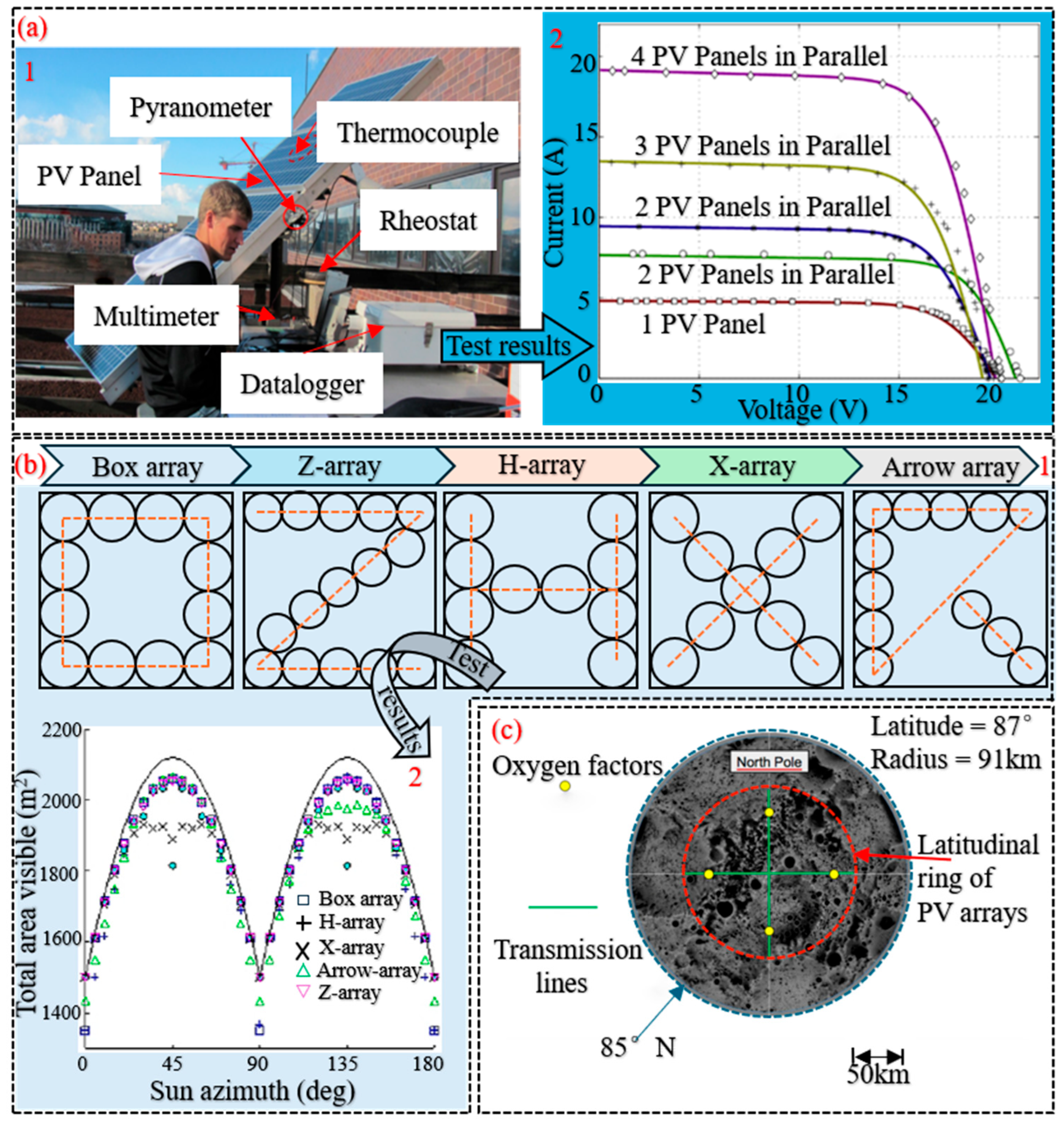
Figure 8(a2). The power generation efficiency of PV arrays varies with their geometric configurations. Halbach et al. [
60] conducted a study examining how array configuration impacts overall system performance (
Figure 8(b1) illustrates arrays with different geometric shapes). Research findings indicate that increasing the ground area diameter of circular arrays significantly enhances solar exposure, thereby improving system power generation efficiency. Moreover, implementing “arrow-shaped” and “X-shaped” configurations reduces the panel area of PV cells while maintaining nearly equivalent solar exposure rates. The solar exposure levels for arrays with different configuration geometries are displayed in
Figure 8(b2). To verify the feasibility of PV arrays on the Moon, Gordon [
61] proposed installing arrays in the lunar polar circumpolar zone (
Figure 8c) based on the unique illumination conditions at the Moon’s poles. These arrays would experience virtually no shadowing, with the PV power generation system’s overall specific mass projected to reach 17 kW/kg. Dyer et al. [
62] performed an exergy analysis on a power system coupling a PV array with an energy storage system. The results indicate that the PV array dominates the exergy performance of the system, and that the battery array significantly enhances the discharging efficiency of the energy storage system.
Figure 8.
Configurations and performance modeling of the PV array. (
a) Parameter calculation model of the cell array: 1—Outdoor PV testing apparatus with real-time measurement instruments; 2—Comparative analysis of experimental and modeled I–V curves for parallel PV panel configurations [
59]. (
b) Arrangement geometries of the cell array: 1—Geometric arrangements of PV arrays for enhanced solar exposure; 2—Optimal exposure assessment for distinct PV cell array layouts in a 100 × 100 m region. (
c) Lunar polar deployment of PV arrays with minimal illumination obstruction [
61].
Figure 8.
Configurations and performance modeling of the PV array. (
a) Parameter calculation model of the cell array: 1—Outdoor PV testing apparatus with real-time measurement instruments; 2—Comparative analysis of experimental and modeled I–V curves for parallel PV panel configurations [
59]. (
b) Arrangement geometries of the cell array: 1—Geometric arrangements of PV arrays for enhanced solar exposure; 2—Optimal exposure assessment for distinct PV cell array layouts in a 100 × 100 m region. (
c) Lunar polar deployment of PV arrays with minimal illumination obstruction [
61].
2.3. Solar Energy Storage Technologies
Given the unique characteristics of the lunar diurnal cycle, nighttime periods near the Moon’s equator can extend up to 354 h. During the lunar night, direct utilization of solar energy for power supply becomes infeasible. Therefore, it has been suggested that the energy harvested throughout the lunar daytime be stored using appropriate methods. This stored energy can then be transformed into a directly usable form during nighttime operations [
12]. According to the underlying mechanisms of material-based energy storage, these methods are generally divided into two main types: thermal storage and physical storage.
2.3.1. Thermal Energy Storage
Thermal energy storage employs heat-retaining materials to absorb solar radiation and store it in the form of thermal energy. The successful implementation of this method relies critically on storage materials exhibiting high specific heat capacity and stable performance. Sampling data from the Apollo missions reveal that around 10–20% of the lunar regolith’s mass is composed of particles less than 20 micrometers in diameter, and that 90% of the particles in the regolith have diameters smaller than 1 mm [
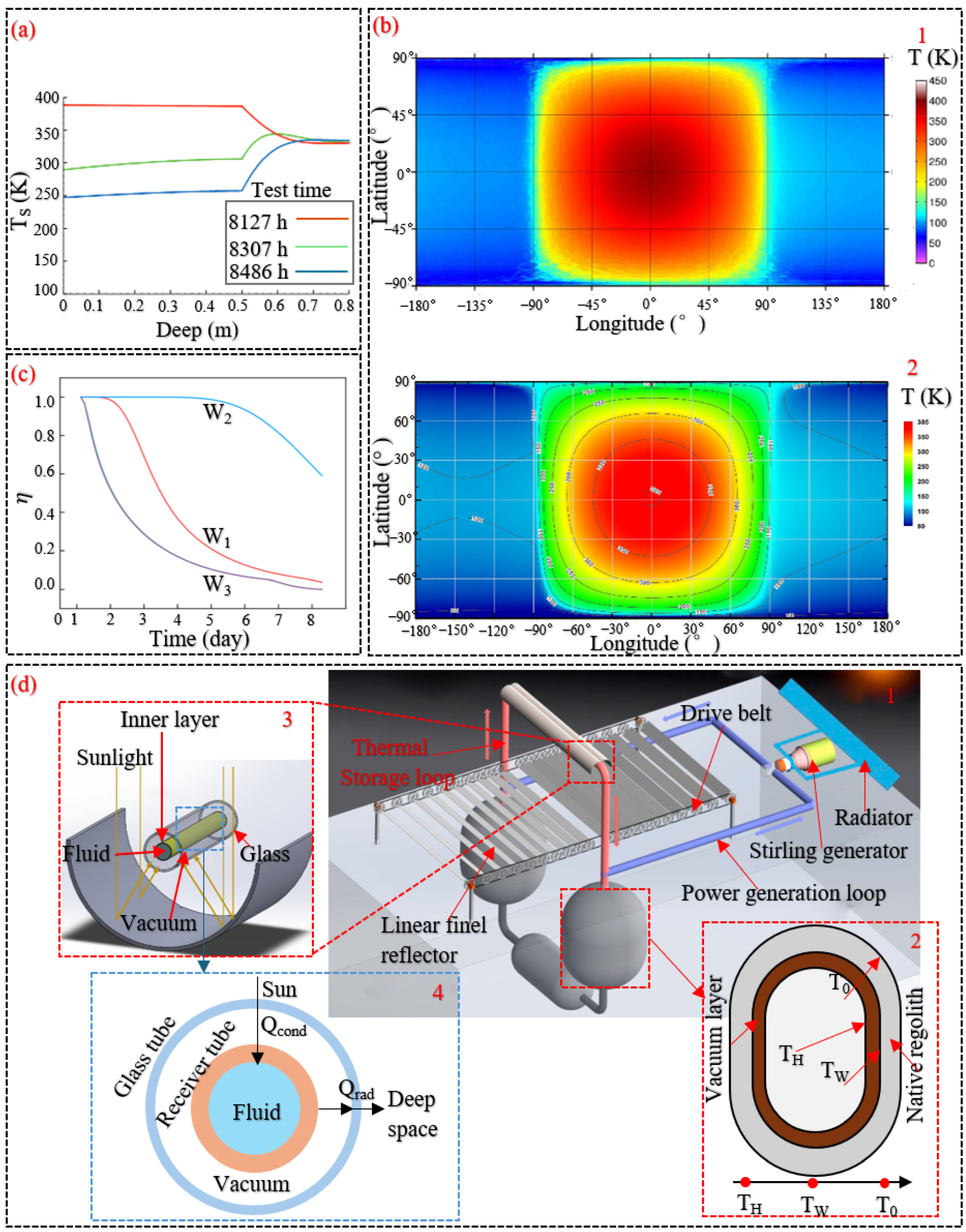
63]. Temperature measurement experiments on the Moon have also demonstrated that the lunar regolith below a depth of 0.6 m maintains a nearly constant temperature of 320 K (
Figure 9a). A lunar regolith layer only a few feet thick can effectively insulate against extreme temperature variations of nearly 300 K [
64]. It can be inferred that the surface lunar regolith is well-suited as a natural thermal storage material. By encapsulating the regolith in sealed containers and introducing a lightweight gas as the thermal storage medium, the system achieves efficient absorption and storage of solar radiant energy during lunar daylight periods [
65]. Building upon this foundation, Kim [
66] established a predictive temperature model for lunar regolith layers. This model enables precise forecasting of lunar surface temperature field distributions, providing critical theoretical support for the thermodynamic design of thermal energy storage systems.
Figure 9b presents a comparison between the measured lunar surface temperature in real time and the corresponding values predicted by the model.
To cope with the severe temperature fluctuations between lunar day and night, Climent et al. [
64,
67] proposed a thermal energy storage system for the lunar surface that integrates heat wadis technology. Heat wadis refer to utilizing modified lunar regolith as the thermal storage medium, maintaining its temperature above 230 K through phase change materials, thereby providing thermal protection for exploration equipment during lunar nights. Hu et al. [
68] optimized the microstructure of lunar regolith. Through numerical simulations of porous media, they demonstrated that regolith with a face-centered cubic stacking configuration exhibits superior thermal storage performance, achieving a thermal storage capacity of 305.6 kilowatt-hours (kWh). By optimizing the porosity and thickness of the lunar regolith insulation layer, Liu et al. [
69] enhanced the thermal energy storage efficiency to 59% after 200 h (
Figure 9c), thereby markedly prolonging the system’s energy retention period. Furthermore, Humble et al. [
70] proposed a conceptual model for a lunar in-situ thermal energy storage and power generation system. This system employs solar concentrators to convert solar radiation into thermal energy stored within modified lunar regolith. During lunar nights, thermal-to-electric conversion is achieved via Stirling engines coupled with intermediate heat exchange units, projecting a specific power output of 8 to 11 W/kg. The architecture of this thermal storage-power generation system is shown in
Figure 9d.
Figure 9.
Thermal energy storage. (
a) Relationship between lunar regolith temperature and subsurface depth [
67]. (
b) Global thermal distribution across the lunar surface: 1—Temperature map derived from Diviner Lunar Radiometer Experiment measurements; 2—Temperature map generated from Lumped system model prediction [
66]. (
c) The relationship between the heat storage efficiency of the three type heat storage systems over time [
69]. (
d) Conceptual layout of a solar thermal storage power generation system utilizing ISRU on the Moon: 1—Overall schematic diagram of the system; 2—Regolith thermal energy reservoir; 3—Trough solar collector; 4—Schematic cross-sectional diagram of the heat collection tube [
45].
Figure 9.
Thermal energy storage. (
a) Relationship between lunar regolith temperature and subsurface depth [
67]. (
b) Global thermal distribution across the lunar surface: 1—Temperature map derived from Diviner Lunar Radiometer Experiment measurements; 2—Temperature map generated from Lumped system model prediction [
66]. (
c) The relationship between the heat storage efficiency of the three type heat storage systems over time [
69]. (
d) Conceptual layout of a solar thermal storage power generation system utilizing ISRU on the Moon: 1—Overall schematic diagram of the system; 2—Regolith thermal energy reservoir; 3—Trough solar collector; 4—Schematic cross-sectional diagram of the heat collection tube [
45].
2.3.2. Physical Energy Storage
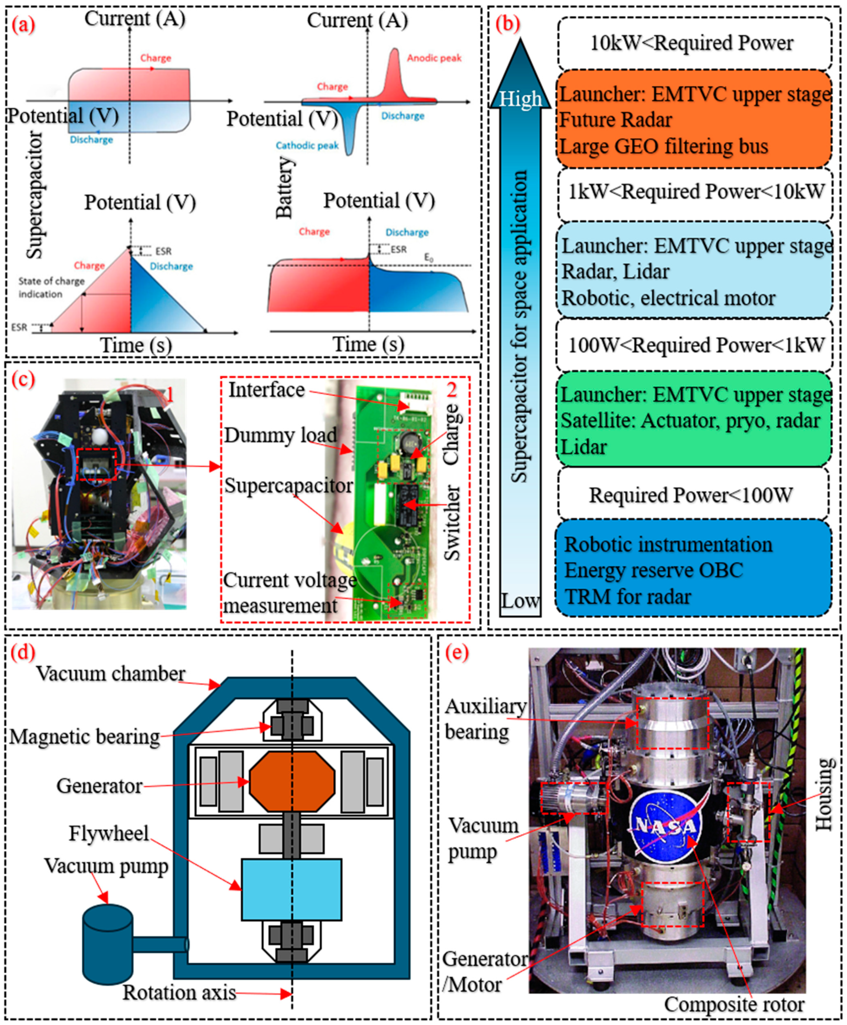
Physical storage encompasses methods that preserve solar energy and its secondary forms via physical mechanisms, rather than relying on chemical transformations. Among them, capacitive storage serves as a representative example of such techniques. Supercapacitors store energy primarily through ion adsorption at the interface between the electrode and electrolyte, in contrast to the electrochemical reactions that govern conventional battery operation. This design enables rapid charge–discharge cycles and exhibits significantly higher power density relative to conventional rechargeable batteries [
71], with comparative performance metrics shown in
Figure 10a. Additionally, supercapacitors exhibit significant advantages including long cycle life, high power output, rapid charge–discharge rates, and low material degradation during operation, enabling diverse space applications (
Figure 10b). However, their operational temperature range (−60 to +60 °C) fails to meet the stringent requirements for extraterrestrial environments [
72]. Recent studies have demonstrated that modifying the microstructure of electrode materials can expand the operational temperature range of capacitors. Devices utilizing reduced graphene oxide as electrode material are capable of functioning across a wide temperature span from −40 to 200 °C [
73]. In practical applications, a Low Earth Orbit (LEO) satellite equipped with supercapacitors has successfully operated for five months, demonstrating that supercapacitors are a viable energy storage device for space applications [
74].
Figure 10c illustrate capacitors implemented in orbital satellites.
In addition, the flywheel energy storage system is another type of physical storage method. These systems employ electromechanical devices to store rotational kinetic energy
), which is determined by the rotor’s angular velocity
and its moment of inertia
, expressed as:
As illustrated in
Figure 10d, the flywheel energy storage system primarily comprises several key elements, including the flywheel or rotor, bearing system, power conversion unit, and auxiliary components [
75]. Flywheel energy storage systems enable short-term electrical energy storage and transfer without requiring charging, making them suitable for medium-scale renewable energy systems such as solar and wind power. Operationally, energy is stored by accelerating the rotor to ultrahigh rotational speeds and released by decelerating the rotor to a complete halt [
76]. Typical rotor speeds range from 20,000 to 50,000 rpm. Under lunar vacuum environment, the flywheel rotor is magnetically suspended within a sealed vacuum chamber, effectively reducing frictional contact between the rotor and the bearing system. With the bearings supporting only one-sixth of the terrestrial weight, the system enables rapid charge and discharge cycles with a high efficiency of about 95% [
77]. In practical applications, NASA’s G2 flywheel (
Figure 10e) operates at 60,000 rpm, delivering an energy storage capacity of 525 watt-hours (Wh) with a charge–discharge power rating of 1 kW [
78].
Figure 10.
Physical energy storage technologies. (
a) Performance comparison between supercapacitors and secondary batteries [
71]. (
b) The applicability of supercapacitors in space based on their required power. (
c) Supercapacitors implemented in LEO satellites: 1—Placement of the supercapacitor test module within the spacecraft flight unit; 2—Photographs of the installed supercapacitor experiment board highlighting its primary components [
74]. (
d) Structural schematic of key components within a flywheel energy storage system. (
e) Physical implementation of the G2 flywheel on spacecraft [
78].
Figure 10.
Physical energy storage technologies. (
a) Performance comparison between supercapacitors and secondary batteries [
71]. (
b) The applicability of supercapacitors in space based on their required power. (
c) Supercapacitors implemented in LEO satellites: 1—Placement of the supercapacitor test module within the spacecraft flight unit; 2—Photographs of the installed supercapacitor experiment board highlighting its primary components [
74]. (
d) Structural schematic of key components within a flywheel energy storage system. (
e) Physical implementation of the G2 flywheel on spacecraft [
78].
3. Thermal Energy Conversion Systems in Space: Dynamic and Static Approaches
Thermal energy on the Moon primarily sourced from solar radiation, radioactive decay occurring within the lunar interior, and heat emitted by operational detection equipment. The majority of lunar thermal energy is utilized for electricity generation through thermoelectric conversion processes, while the remainder is applied in thermal regulation systems and material processing, providing critical support for the construction of future lunar bases [
79]. Thermoelectric conversion processes are categorized into dynamic and static power generation based on operational motion characteristics.
3.1. Dynamic Thermal Power Generation Technologies
In dynamic thermal power generation technologies, the working fluid drives the motion of mechanical components within the system through distinct thermodynamic cycle processes. The kinetic energy of these mechanical components then powers the generator, ultimately producing electrical energy. The thermodynamic cycles are primarily categorized into three types: Stirling cycle, Brayton cycle, and Rankine cycle [
3]. The following sections provide concise descriptions of these cycle-based power generation technologies.
3.1.1. Stirling Cycle Power Generation
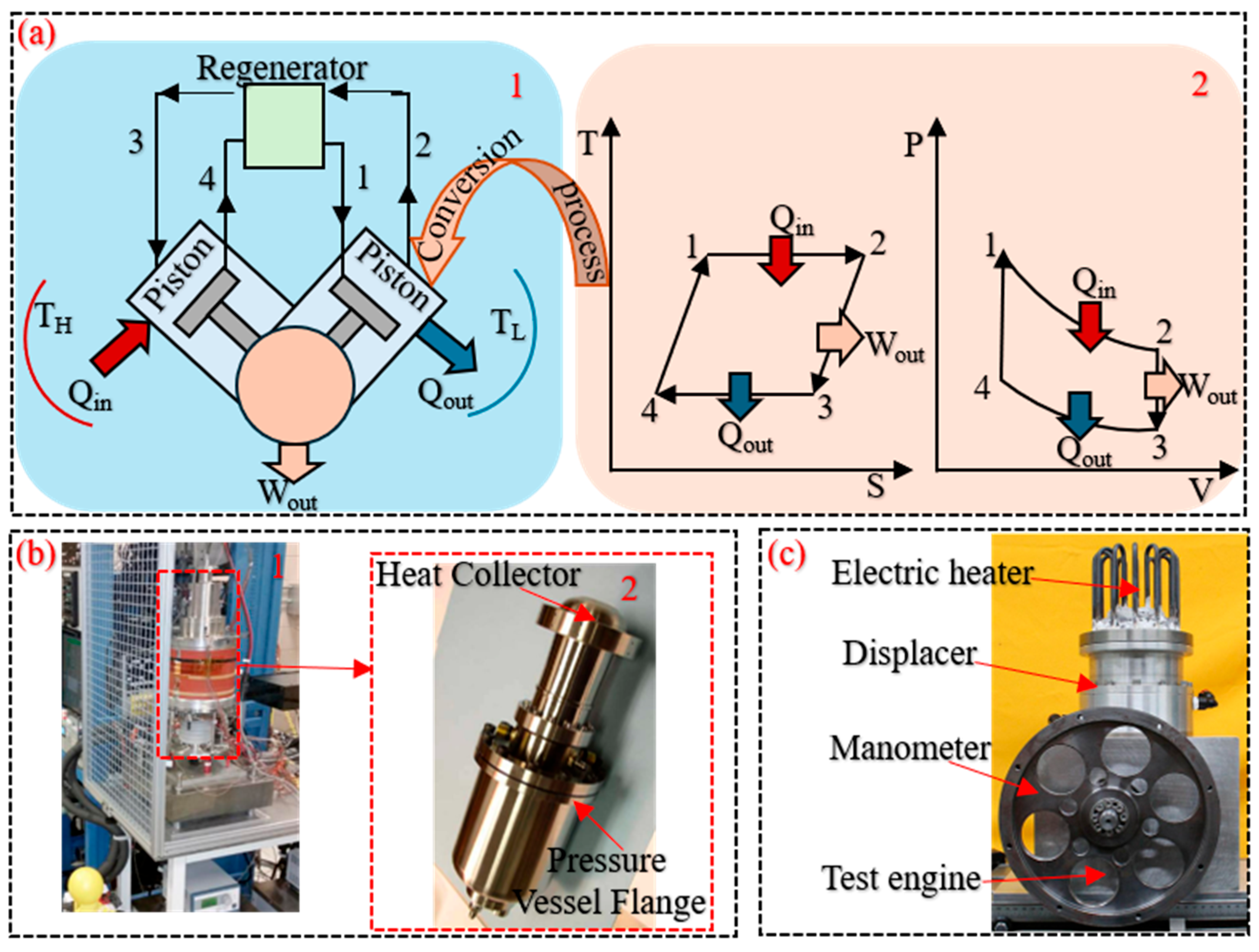
Stirling cycle power generation relies on the Stirling engine within the system for electricity generation. The Stirling engine operates on the Stirling cycle, which consists of two isothermal processes and two isochoric (constant-volume) processes. As illustrated in
Figure 11a, the cycle proceeds through the following four stages: 1–2 isothermal expansion, 2–3 constant-volume heat input, 3–4 isothermal compression, and 4–1 constant-volume heat rejection [
80]. The Stirling engine retains the same working gas throughout all conversion processes, with heat exchange operations consistently conducted under isothermal conditions, enabling high thermal efficiency and offering significant advantages in waste heat recovery.
During the 1980s, the NASA was the first to develop a Stirling engine capable of operating in space. This engine was integrated into a free-piston thermoelectric conversion system, which employed a displacer and a power piston functioning within a pressurized helium atmosphere [
83]. The results demonstrated that the system achieved a specific power output close to 100 W/kg. To date, NASA has developed two generations of space Stirling engine [
84]: the first generation features a balanced dual β-type engine with flexible supports, while the second generation utilizes gas bearings to support the displacer assembly in a balanced dual β-type configuration (
Figure 11b). In contrast, the ESA has not developed a Stirling engine for space applications. The Rutherford Appleton Laboratory and the University of Oxford [
82] jointly developed A β-type space Stirling engine with output of 300 W (
Figure 11c). The system achieved a measured output power of 390 W and demonstrated a thermal efficiency of 32.2%.
Thermoacoustic power generation technology also employs the Stirling cycle; however, it relies on a thermoacoustic generator within the system for electricity generation. The thermoacoustic generator primarily consists of an electromagnetic transducer, a piezoelectric device, a magnetohydrodynamic device, and a bidirectional turbine, as illustrated in
Figure 12a. A thermoacoustic generator operates by converting thermal energy from the system into mechanical energy manifested as acoustic waves, which are subsequently converted into electrical power [
84,
85].
Since 2000, ESA and NASA have conducted multiple research and development efforts on thermoacoustic generators. In one feasibility study, ESA investigated the integration of a thermoacoustic-magnetohydrodynamic device into a space power conversion system [
86]. Jensen and Raspet [
87] developed an efficient piezoelectric monocrystalline transducer. By substituting this transducer for the electromagnetic transducer, the system’s power generation efficiency reached 10% of the Carnot cycle efficiency. Furthermore, Zhou et al. [
88] optimized the architecture of thermoacoustic generators by reducing the number of moving components to simplify thermoacoustic Stirling engines. The displacer piston in the thermoacoustic generator was replaced with a thermoacoustic tube, reducing the system’s overall complexity and sensitivity to vibration, and increasing the thermoacoustic conversion efficiency to 30%.
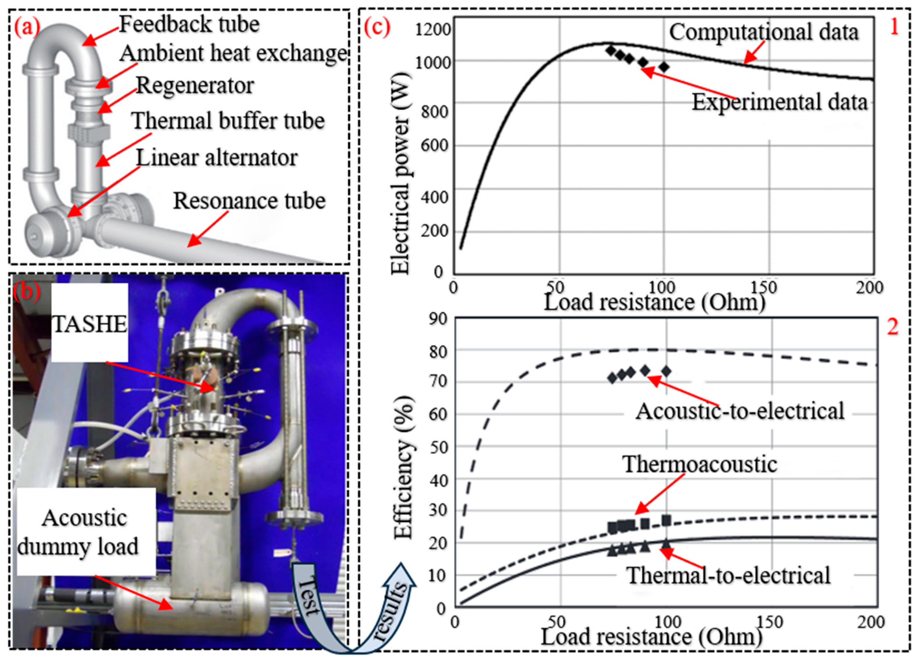
Figure 12b shows the improved thermoacoustic generator. Wu et al. [
89] developed a kilowatt-class thermoacoustic generator, operating in an argon environment at a 4.5% mole fraction and maintaining an operating frequency of 64 Hz Under these conditions, the system generated 1043 Wh of electrical energy, and the test results (
Figure 12c) indicated a thermoelectric conversion efficiency of 17.7%. As the thermoelectric conversion efficiency of thermoacoustic generator continues to increase, this novel power generation device holds significant potential for future space applications.
Figure 12.
Thermoacoustic power generation technology. (
a) Three-dimensional model of the thermoacoustic generator. (
b) Thermoacoustic generator testing [
90]. (
c) Test results of the kilowatt-class thermoacoustic generator: 1—Variation of simulated and measured electrical output with respect to load resistance; 2—Resistance-dependent trends of calculated and experimental efficiencies conversion [
89].
Figure 12.
Thermoacoustic power generation technology. (
a) Three-dimensional model of the thermoacoustic generator. (
b) Thermoacoustic generator testing [
90]. (
c) Test results of the kilowatt-class thermoacoustic generator: 1—Variation of simulated and measured electrical output with respect to load resistance; 2—Resistance-dependent trends of calculated and experimental efficiencies conversion [
89].
3.1.2. Brayton Cycle Power Generation
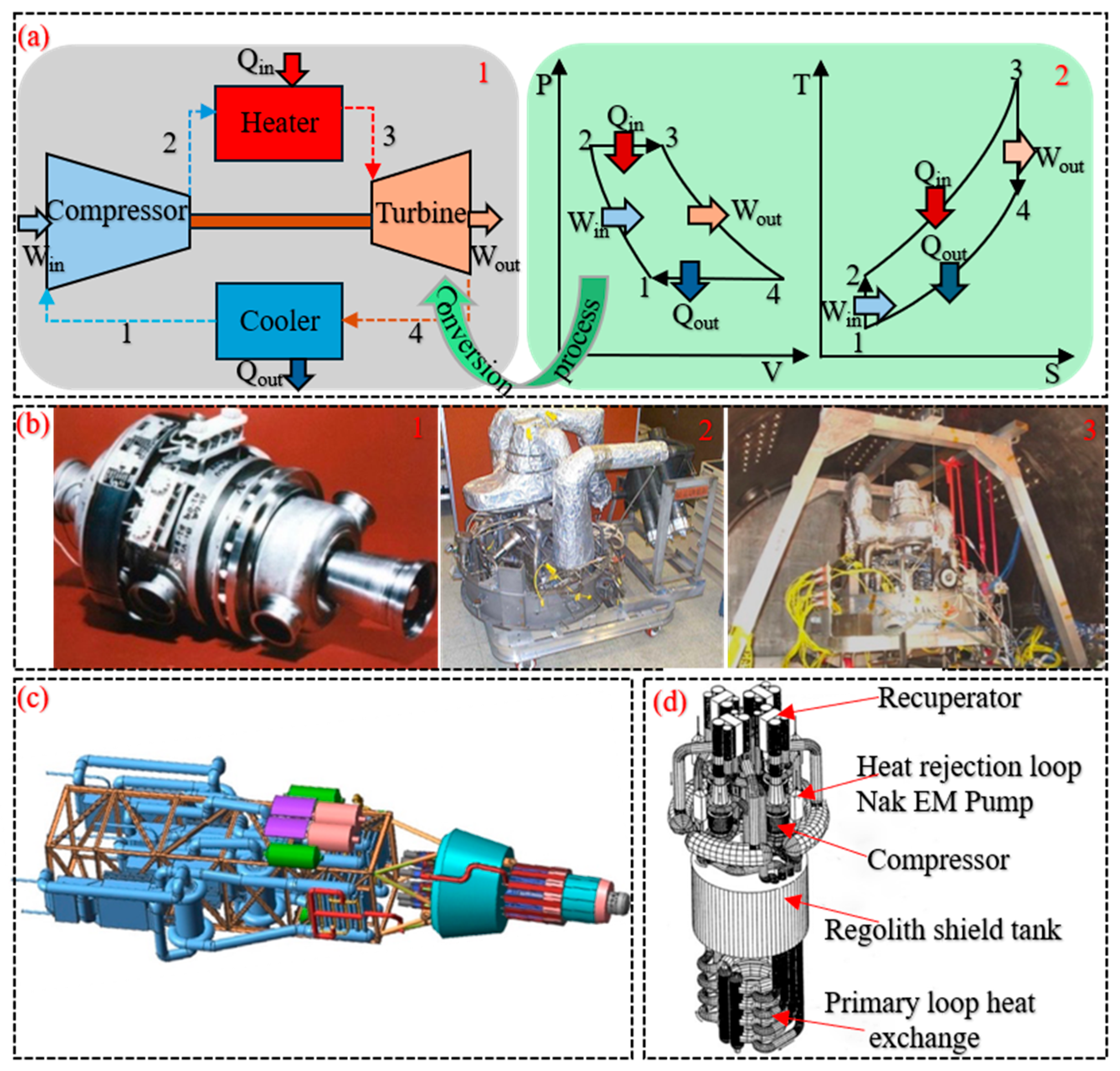
Brayton cycle power generation relies on an engine operating on the Brayton cycle to produce electricity. The energy conversion processes of the Brayton cycle are illustrated in
Figure 13(a2): 1–2, isentropic compression; 2–3, isobaric heat addition; 3–4, isentropic expansion; and 4–1, isobaric heat rejection [
91]. A Brayton cycle engine typically consists of a heater, a turbo compressor, a cooler, and a recuperator (see schematic in
Figure 13(a1)). During operating conditions, the system employs a noble gas mixture—commonly helium combined with xenon—as the working fluid. Helium demonstrates excellent heat transfer performance within the heater, cooler, and regenerator, whereas xenon contributes to molecular weight adjustment, optimizing the aerodynamic properties and enhancing the efficiency of the turbine-compressor unit [
92].
Since the 1970s, NASA has pursued the development of space-based power generation systems utilizing the closed Brayton cycle, aiming to enhance the thermoelectric conversion efficiency from diverse heat sources (solar radiation, nuclear reactor fission, radioactive isotope decay) to electrical energy [
93]. Prototypes of power conversion units in the 2 to 15 kilowatt-class range have been developed, demonstrating thermoelectric conversion efficiencies around 30% with cumulative operational durations exceeding 40,000 h [
92]. The 2 kilowatt-class prototype is shown in
Figure 13b. In the early 21st century, NASA collaborated with the Department of Energy, the Jupiter Icy Moons Orbiter (JIMO) program, and the Prometheus Project to develop space thermoelectric conversion systems employing closed Brayton cycle. These systems were designed for electrical power outputs ranging from 100 to 200 kW [
94], with the nuclear-powered conversion unit illustrated in
Figure 13c. Additionally, in support of NASA’s planetary surface nuclear fission power initiative, Mason [
95] developed a closed Brayton cycle conversion system (
Figure 13d) to supply electrical power from small nuclear reactor thermal sources for production activities on lunar and Martian surfaces.
Figure 13.
Brayton cycle power generation technology. (
a) Brayton cycle conversion process: 1—Isobaric transformation curve; 2—Schematic diagram of engine components. (
b) 2 kilowatt-class Brayton power conversion unit for space applications: 1—Turbine–compressor; 2—Brayton power conversion unit prototype; 3—Mechanical vibration testing. (
c) 135 kilowatt-class Brayton liquid metal reactor (designed for JIMO). (
d) 550 kilowatt-class Brayton power conversion unit for lunar surface operations [
96].
Figure 13.
Brayton cycle power generation technology. (
a) Brayton cycle conversion process: 1—Isobaric transformation curve; 2—Schematic diagram of engine components. (
b) 2 kilowatt-class Brayton power conversion unit for space applications: 1—Turbine–compressor; 2—Brayton power conversion unit prototype; 3—Mechanical vibration testing. (
c) 135 kilowatt-class Brayton liquid metal reactor (designed for JIMO). (
d) 550 kilowatt-class Brayton power conversion unit for lunar surface operations [
96].
3.1.3. Rankine Cycle Power Generation
Power generation based on the Rankine cycle involves energy transfer through the phase transition of the working fluid, enabling the conversion of thermal energy into electrical output. Unlike the other two thermodynamic cycles, the Rankine cycle compresses the working fluid in its liquid state, which significantly reduces the compression work [
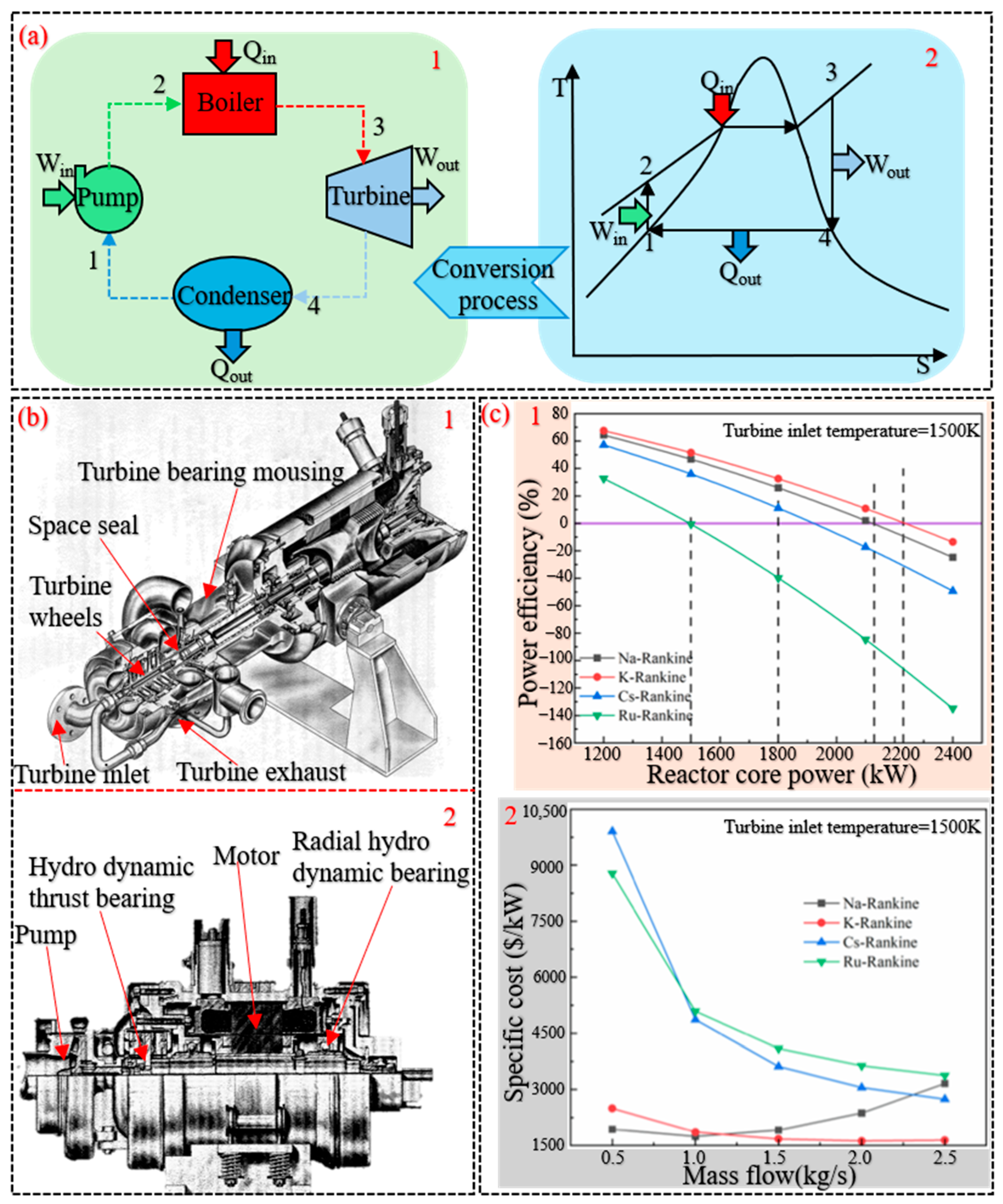
97]. As shown in
Figure 14(a1), a conventional Rankine cycle power system generally includes a feedwater pump, boiler, steam turbine, and condenser. The corresponding thermodynamic process, illustrated in
Figure 14(a2), involves the following stages: 1–2 isentropic expansion, 2–3 constant-pressure heat rejection, 3–4 isentropic compression, and 4–1 constant-pressure heat input [
98].
Within the U.S. space power program, thermoelectric conversion systems rated at 100 kW and above typically employ the Rankine cycle. From 1955 to 1973, NASA first implemented Rankine cycle power generation technology in space thermoelectric conversion systems under the Space Nuclear Auxiliary Power (SNAP) Program. The operational process of the system is as follows: a nuclear fission reactor functions as the primary heat source, transferring thermal energy to the working fluid. This fluid, once heated, expands through a turbine to drive a generator and produce electrical power. It is then cooled and condensed by a condenser, thereby closing the cycle [
99].
During the SNAP program, NASA made multiple improvements to Rankine cycle-based space thermoelectric conversion systems. The thermoelectric conversion system for SNAP-2 employed mercury as the Rankine cycle working fluid. The mercury was vaporized in a boiler and then expanded through a two-stage axial-flow turbine to perform external work. Simultaneously, the mercury vapor was used to cool the generator, while liquid mercury served as a lubricant, greatly simplifying the system’s architecture [
100]. In SNAP-8, the thermoelectric converter was upgraded to a four-stage axial-flow turbine, and the boiler was fitted with a counterflow heat exchanger to interface with the sodium-potassium alloy (NaK) loop in the nuclear reactor. This converter could effectively utilize regenerative heat, enhancing the system’s overall thermoelectric conversion efficiency; however, component corrosion issues arose during operation [
101].
Figure 14b illustrates the related apparatus of this thermoelectric converter. Building upon this, the thermal system for SNAP-50 employed potassium as the Rankine cycle working fluid, using the boiler of the lithium reactor’s primary loop for heating. A four-stage axial-flow turbine driven by potassium vapor was then condensed by a condenser, improving efficiency while reducing corrosion issues in the system’s components [
102]. Sun et al. [
103] performed an in-depth evaluation of Rankine cycle performance by analyzing efficiency, economic viability, and mass characteristics when employing four alkali metals—sodium, potassium, cesium, and rubidium—as working fluids (see
Figure 14c for results). Their found that cycles using cesium and potassium are suitable for space-based power system, while the sodium, due to its higher mass, is better adapted for use in terrestrial power systems.
Figure 14.
Rankine cycle power generation technology. (
a) Rankine cycle conversion process: 1—Schematic diagram of power generation system; 2—T-S diagram [
97]. (
b) Thermoelectric conversion device in the SNAP-8 program: 1—Turbine assembly; 2—NaK pump loop. (
c) Results of Rankine cycle using different working fluids: 1—Power efficiency across a range of core power levels; 2—Specific weight for various mass flows [
103].
Figure 14.
Rankine cycle power generation technology. (
a) Rankine cycle conversion process: 1—Schematic diagram of power generation system; 2—T-S diagram [
97]. (
b) Thermoelectric conversion device in the SNAP-8 program: 1—Turbine assembly; 2—NaK pump loop. (
c) Results of Rankine cycle using different working fluids: 1—Power efficiency across a range of core power levels; 2—Specific weight for various mass flows [
103].
3.2. Static Thermal Power Generation Systems
In static thermal power generation systems, electricity is produced by employing the intrinsic physical properties of specific materials. These systems generate electrical energy through distinct energy conversion effects, and are accordingly categorized into three types: thermoelectric system, thermionic system, and thermophotovoltaic system.
3.2.1. Thermoelectric System
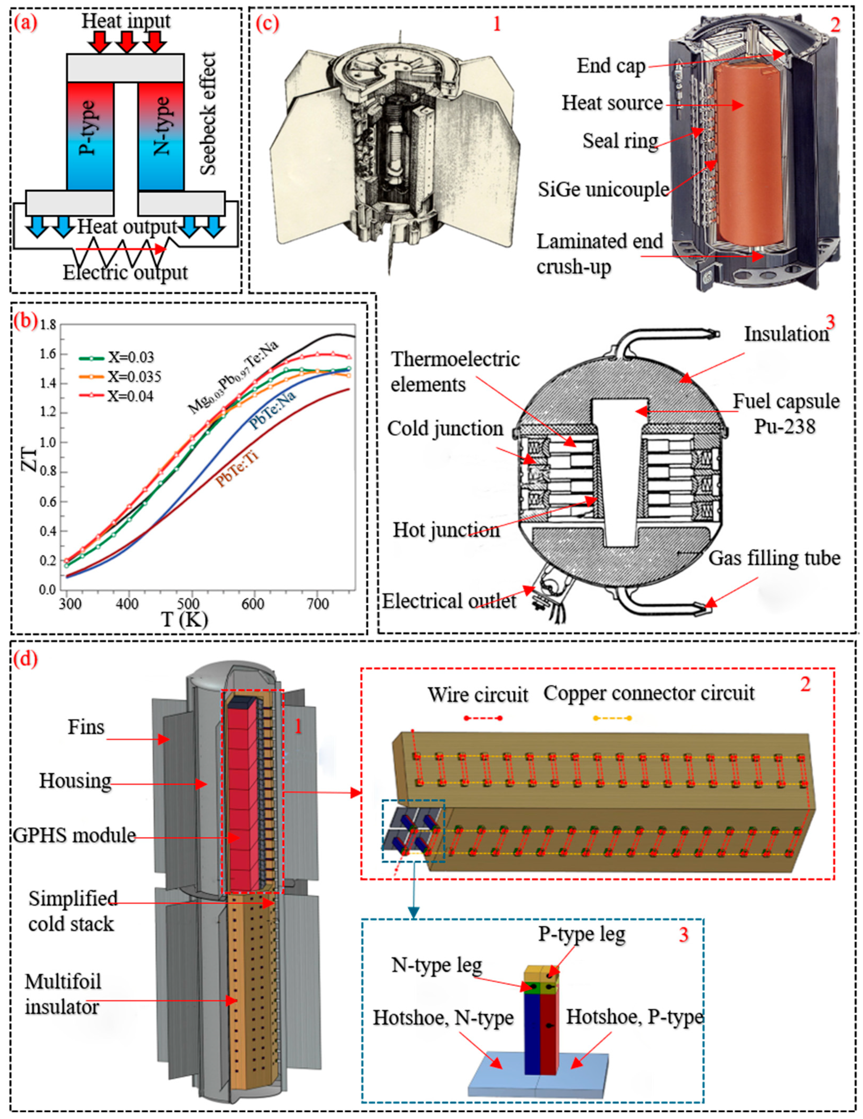
Thermoelectric systems operate by using thermoelectric converters to generate electricity through the Seebeck effect under a temperature gradient, as illustrated in
Figure 15a. The thermoelectric converters are typically composed of paired thermoelectric elements made of p-type and n-type semiconductor materials. Their performance is evaluated by the dimensionless figure of merit
, defined as:
where,
,
and
represent the thermal conductivity, electrical resistivity, and absolute temperature of the thermoelectric material, respectively. The term
is referred to as the power factor [
104]. Since thermoelectric converters use pairs of p-type and n-type semiconductor materials, the system’s thermoelectric conversion efficiency depends on the property relationship between each material pair. In Thermoelectric Generator (TEG) applications, the thermoelectric converter should incorporate material pairs exhibiting the highest figure of merit within the target temperature range—including the temperatures of the hot and cold sides as well as their ratio—in order to maximize energy conversion efficiency [
13].
Figure 15b shows the figure of merit for different materials.
Since the 1960s, TEGs combined with nuclear reactor heat sources have been widely employed as thermoelectric systems in space exploration missions [
105]. The SNAP-3B thermoelectric system (
Figure 15(c3)) functioned as the power supply for radio transmitters on the Transit 4A and Transit 4B navigation satellites. It operated with a hot-side temperature of 783 K and a cold-side temperature of 366 K, delivering an electrical output of 2.7 W [
6]. The thermoelectric system of the SNAP-9 program was further improved, raising the cold-side operating temperature to 431 K and achieving an output power of 26.8W [
106]. In the SNAP-19 program, the thermoelectric system underwent an upgrade in its converter materials, replacing the semiconductor pair with TAGS-85 for the p-type leg and 3M-TAGS for the n-type leg. The device operated at hot-side temperatures between 785 and 820 K, and cold-side temperatures ranging from 430 to 450 K, yielding an output power of 40 W [
107]. The TEG prototype is shown in
Figure 15(c1). The TEG employed in the SNAP-27 program provided power to the scientific instruments of the Apollo Lunar Surface Experiments Package. It operated with a hot-side temperature of around 870 K and a cold-side temperature ranging between 495 and 547 K, yielding an output power of 73 W. The Multi-Hundred Watts Radioisotope Thermal Generator (MHW-RTG) employed silicon-germanium thermocouples as its thermoelectric converter, operating with a hot-side temperature of 1273 K and a cold-side temperature of 573 K. Its electrical power output ranged from 125 to 157 W, and it was used to supply power to the satellite LES-8 and the spacecraft Voyager 1 and Voyager 2 [
108]. The MHW-RTG is shown in
Figure 15(c2). The General Purpose Heat Source Radioisotope Thermoelectric Generator (GPHS-RTG) provides an electrical output in the range of 246 to 289 W and has been employed to supply substantial power for major deep space missions, including Galileo, Ulysses, Cassini, and New Horizons. The structure of the GPHS-RTG and its principal components are illustrated in
Figure 15d.
Figure 15.
Thermoelectric systems. (
a) Operating principle of a thermoelectric system. (
b) Temperature dependence of the FOM for various thermoelectric materials [
109]. (
c) Historical spaceflight applications of thermoelectric systems: 1—TEG used in the SNAP-19 mission; 2—MHW-RTG; 3—TEGs used on Transit 4A and Transit 4B [
110]. (
d) Structural schematic of the GPHS-RTG: 1—Exploded view of the GPHS-RTG assembly; 2—Exploded diagram of the thermoelectric array and its electrical connection layout; 3—Simplified representation of a unicouple unit within the system [
111].
Figure 15.
Thermoelectric systems. (
a) Operating principle of a thermoelectric system. (
b) Temperature dependence of the FOM for various thermoelectric materials [
109]. (
c) Historical spaceflight applications of thermoelectric systems: 1—TEG used in the SNAP-19 mission; 2—MHW-RTG; 3—TEGs used on Transit 4A and Transit 4B [
110]. (
d) Structural schematic of the GPHS-RTG: 1—Exploded view of the GPHS-RTG assembly; 2—Exploded diagram of the thermoelectric array and its electrical connection layout; 3—Simplified representation of a unicouple unit within the system [
111].
3.2.2. Thermionic System
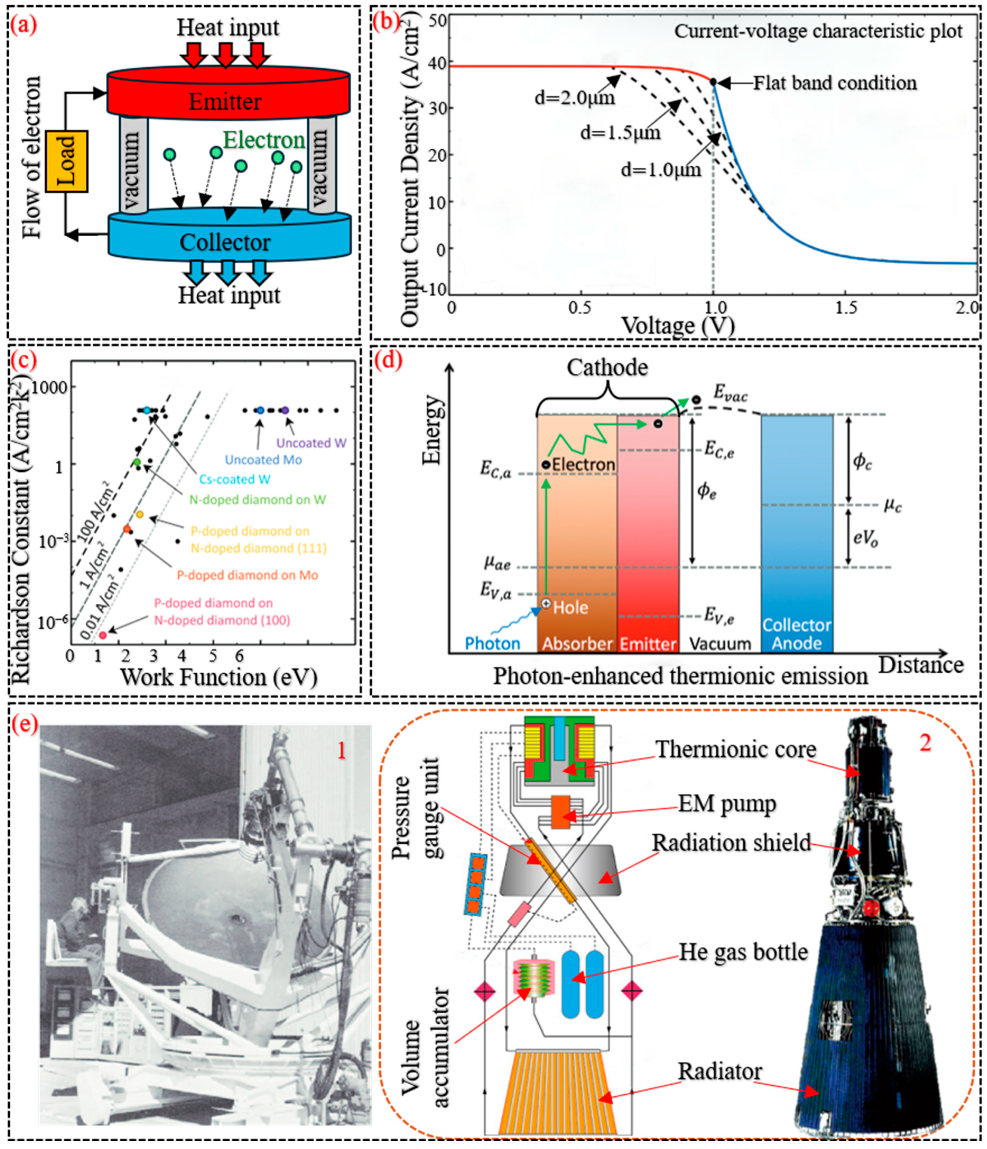
Thermionic power generation utilizes a Thermionic Energy Converter (TEC) to directly transform thermal energy into electrical power. As illustrated in
Figure 16a, a typical TEC comprises two main electrodes: a high-temperature emitter (cathode) and a cooler collector (anode), which are separated by a vacuum gap, along with the associated electrical load and interconnecting circuitry. The working mechanism of a TEC involves the emission of electrons from the heated emitter once they gain enough energy to surpass the material’s work function. These electrons accumulate at the cooler collector, generating a potential difference, which subsequently drives an electric current through an external circuit [
112].
Figure 16b presents a representative I–V characteristic curve for a thermionic system. The system’s current density (
is determined by the cathode’s work function (
) and absolute temperature (
), and is expressed as:
where
is the Richardson constant of the electrode material [
113]. From Equation (9), it follows that, to achieve a higher current density, the emitter of the TEC must possess a larger Richardson constant and a relatively lower work function, and the TEC’s operating temperature will be constrained by the choice of electrode material. The work functions and Richardson constants of various electrode materials are shown in
Figure 16c.
TECs were initially manufactured in the 1950s, achieving a thermoelectric conversion efficiency of 10 to 15% under experimental conditions. Subsequently, NASA and the USSR each developed multiple thermionic systems for space applications. In 1962, the NASA completed the development of a prototype TEC for space applications (
Figure 16(e1)) and integrated it into the SNAP-13 program. The device operated within a temperature range of 1600 to 1700 K, delivering an electrical output of 12.25 W and achieving a specific power of 1 W/kg [
114]. Meanwhile, USSR also developed two space thermionic reactor systems: the single-cell thermionic fuel system, designated TOPAZ II, and the multi-cell thermionic fuel system, designated TOPAZ I [
115]. TOPAZ I demonstrated a thermoelectric conversion efficiency of over 7.5%, with its emitter operating at a temperature of 1723 K and achieving a system-specific power output exceeding 30 W/kg. In comparison, the emitter in TOPAZ II functions at approximately 2100 K, yielding a lower conversion efficiency of 5.2% and a specific power output of 5.2 W/kg [
116]. A schematic representation of the TOPAZ II system is shown in
Figure 16(e2).
In 1990, Snydert and Sgammato [
117] optimized the electrodes of the TEC. The collector electrode was fabricated from chemical vapor deposition tungsten, and the emitter electrode was produced from directionally solidified tungsten. Following these improvements, the thermionic system achieved a thermoelectric conversion efficiency of approximately 13% and a specific power of 13.4 W/kg. In 2015, ESA first introduced Photon-Enhanced Thermionic Emission (PETE) technology. In PETE, photons from solar radiation promote the emission of electrons from the emitter in TECs, thereby improving thermionic conversion efficiency. TECs incorporating PETE are anticipated to serve as effective power-supply units for deep-space exploration [
118].
Figure 16d presents the PETE process in a heterostructure emitter.
Figure 16.
Thermionic system. (
a) Schematic diagram of a TEC. (
b) I–V characteristic curve of a representative TEC. (
c) Comparison of work function and Richardson constant values for various TEC electrode materials. (
d) Electron motive diagram illustrating PETE with a heterostructure emitter. In the schematic,
and
denote the work functions of the emitter and collector, respectively;
and
represent the Fermi levels of the absorber-emitter and collector;
corresponds to the output voltage normalized by the elementary charge; and
indicates the maximum valence band energy level of the emitter [
119]. (
e) Thermionic systems utilized in space: 1—The NASA solar TEC prototype; 2—TOPAZ-II schematic [
120].
Figure 16.
Thermionic system. (
a) Schematic diagram of a TEC. (
b) I–V characteristic curve of a representative TEC. (
c) Comparison of work function and Richardson constant values for various TEC electrode materials. (
d) Electron motive diagram illustrating PETE with a heterostructure emitter. In the schematic,
and
denote the work functions of the emitter and collector, respectively;
and
represent the Fermi levels of the absorber-emitter and collector;
corresponds to the output voltage normalized by the elementary charge; and
indicates the maximum valence band energy level of the emitter [
119]. (
e) Thermionic systems utilized in space: 1—The NASA solar TEC prototype; 2—TOPAZ-II schematic [
120].
3.2.3. Thermophotovoltaic System
TPV power generation involves the direct conversion of thermal radiation from a heat source into electricity using TPV cells. In a TPV system, the heat source is coupled to an emitter via radiative transfer or conductive heat transfer; the emitter then emits photons onto the TPV cells, which convert the energy of these photons into electronic energy, thereby generating electricity [
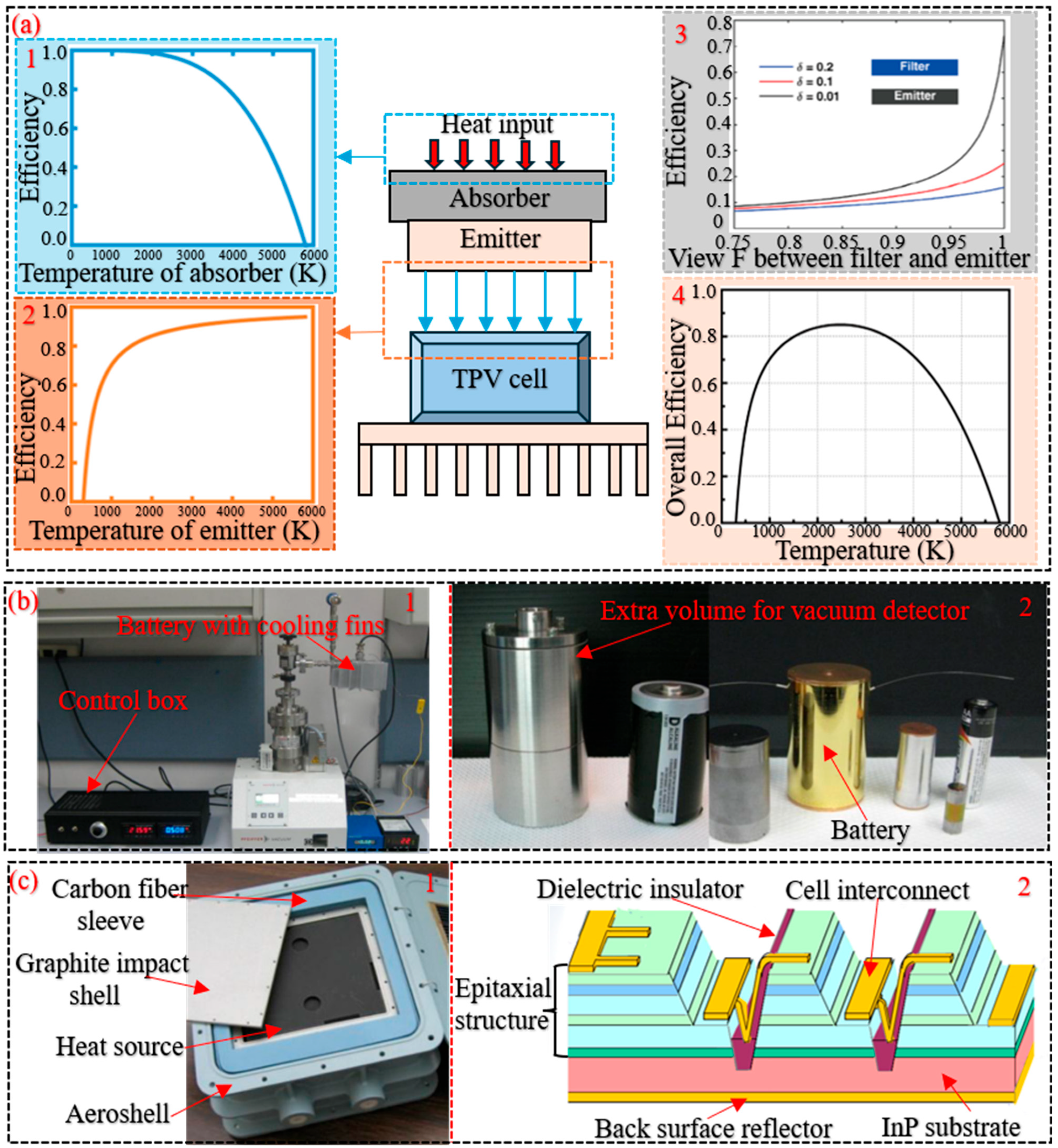
121]. A schematic diagram of the system components is shown in
Figure 17a. Compared with STPV technology, the heat source in a TPV system can originate from multiple avenues—such as nuclear thermal energy and waste heat—without relying on solar radiation. Under ideal conditions, the overall system efficiency (
) can be expressed as:
where
,
and
denote the temperatures of the absorber, the emitter, and the TPV cell, respectively.
Additionally, system efficiency is also affected by the radiative intensity; the infrared radiative intensity (
, emitted by the heat source can be quantified by the Stefan-Boltzmann Law (SBL):
where
denotes the SBL constant, and
represents the temperature of the heat source [
122]. As indicated by Equations (10) and (11), the TPV system’s conversion efficiency can be markedly improved by adjusting the operating temperature and enhancing the thermal radiative intensity of the heat source.
Figure 17a shows the energy conversion efficiency at each stage of the system.
Figure 17.
TPV system. (
a) Component and operational diagram of the TPV System: 1—Efficiency curve of thermal radiation transfer from the heat source to the absorber; 2—Efficiency curve from the emitter to the TPV cell; 3—Comparative efficiency of various emitter–filter configurations; 4—The overall efficiency of an ideal TPV system [
31]. (
b) RTPV system developed by General Atomics: 1—RTPV power system testing set up; 2—Watt and milliwatt scale TPV system hardware. (
c) TPV system developed by the NASA: 1—Power supply unit; 2—Schematic diagram of the InGaAs TPV cell on an InP substrate [
123].
Figure 17.
TPV system. (
a) Component and operational diagram of the TPV System: 1—Efficiency curve of thermal radiation transfer from the heat source to the absorber; 2—Efficiency curve from the emitter to the TPV cell; 3—Comparative efficiency of various emitter–filter configurations; 4—The overall efficiency of an ideal TPV system [
31]. (
b) RTPV system developed by General Atomics: 1—RTPV power system testing set up; 2—Watt and milliwatt scale TPV system hardware. (
c) TPV system developed by the NASA: 1—Power supply unit; 2—Schematic diagram of the InGaAs TPV cell on an InP substrate [
123].
In the 1990s, TPV power generation technology was first developed jointly by Bettis National Laboratory and Knolls Atomic Power Laboratory [
123]. Subsequently, General Atomics [
124] developed milliwatt-to-watt-class Radioisotope Thermophotovoltaics (RTPV) systems. Under test conditions, the conversion efficiency of the milliwatt-class systems was below 1%, while that of the watt-class systems ranged from 7.5 to 10%.
Figure 17b shows the associated test apparatus. Building upon this foundation, NASA upgraded the heat source and developed a TPV system utilizing the GPHS [
125], as depicted in
Figure 17(c1). The system integrates Indium Gallium Arsenide (InGaAs) TPV cells fabricated on an Indium Phosphide (InP) substrate, with the cell architecture illustrated in
Figure 17(c2). The system achieved an output power of 38 W, a thermoelectric conversion efficiency of approximately 15%, and a specific power ranging from 6 to 8 W/kg. In 2005, He et al. [
126] developed a TPV system incorporating a micro-scale gap. By controlling the separation between the emitter and TPV cell to remain below one micrometer, the enhanced near-field radiative transfer significantly increased the infrared energy flux reaching the TPV cell, thereby enhancing the system’s overall conversion efficiency.
3.3. Evaluation of Thermoelectric Conversion Parameters
This section presents a comparative evaluation of the technical specifications of multiple space-based thermoelectric conversion systems, aiming to summarize the distinguishing features of various thermal power generation technologies.
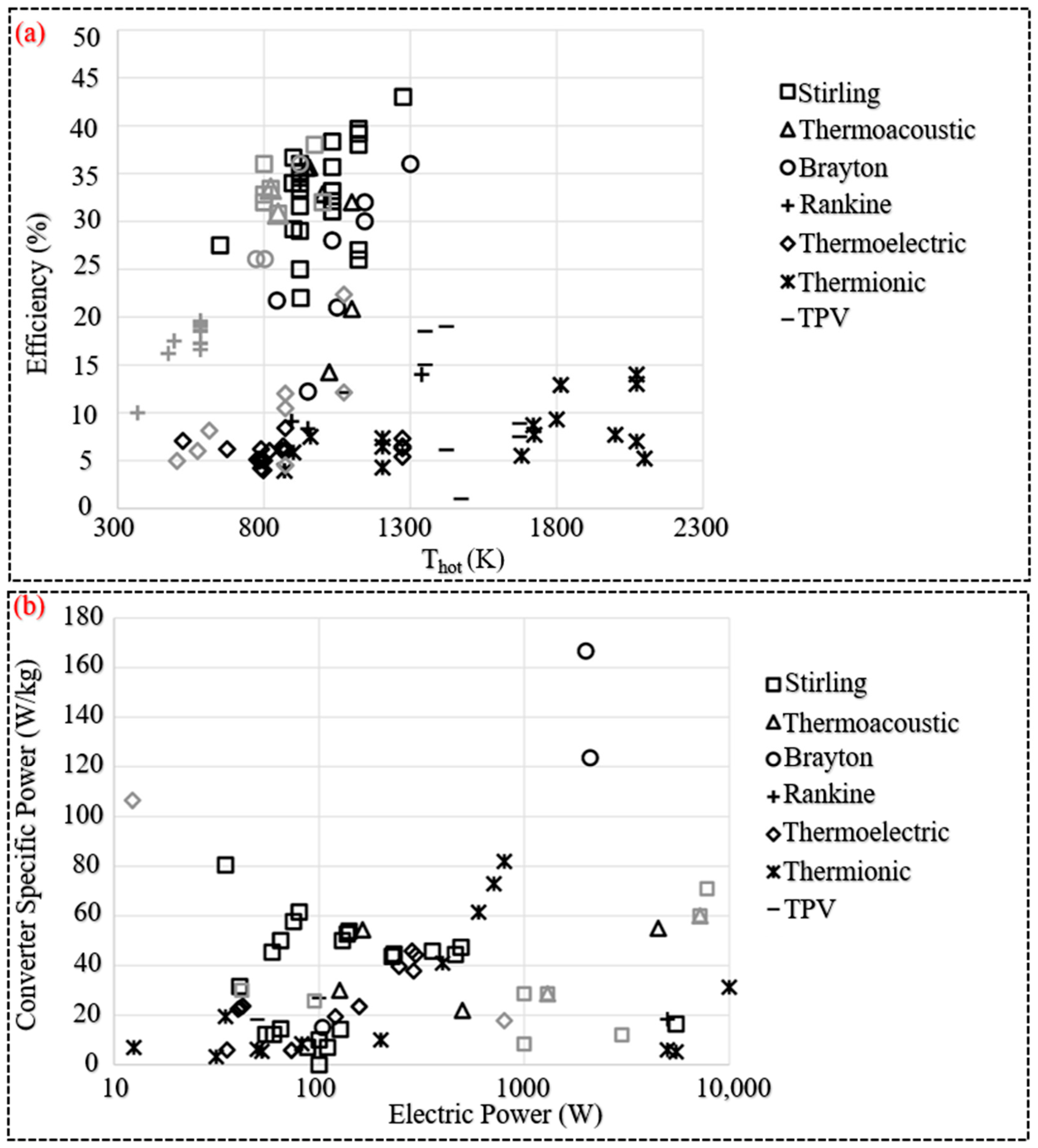
Dynamic power generation technologies demonstrate higher thermoelectric conversion efficiency compared to static systems. As illustrated in
Figure 18a, when the temperature ratio between the hot and cold sides of the thermoelectric converter is less than 4, dynamic systems typically achieve efficiencies above 15%, whereas static systems generally remain below this threshold.
As illustrated in
Figure 18b, the specific power of thermoelectric conversion systems varies depending on the output power level. For systems producing less than 100 W, the Stirling engine exhibits the highest specific power, reaching up to 80 W/kg. In contrast, at output powers exceeding 1 kW, the specific power of the Brayton engine surpasses 120 W/kg. Within the 100 to 1000 W range, both Stirling engines and thermoelectric systems demonstrate specific power values between 40 and 60 W/kg [
3].
In terms of operational lifespan, thermoelectric systems have been operating successfully in space for decades, and TEGs have been deployed on multiple space exploration missions [
127]. The Brayton engine has passed NASA durability tests, and its operational lifespan in space is excepted to reach 5 to 10 years [
92]. The working fluids used in Rankine cycle generation systems tend to be corrosive, and the feasibility of this technology in space has only been validated over limited operating durations [
106]. In comparison, thermionic and TPV systems exhibit shorter lifespans: the former, in USSR high-temperature nuclear fission reactor applications, operates for 1 to 3 years; the latter has not yet seen practical deployment, with operation under experimental test conditions lasting approximately 1000 h [
112].
In summary, within dynamic power generation technologies, the structures of the Stirling engine, Brayton engine, and Rankine engine become progressively more complex, with corresponding increases in thermoelectric conversion efficiency. As engine size grows, the abundance of moving parts and circulating working fluid makes these devices susceptible to aging and necessitates ongoing maintenance during operation. In contrast, static power generation systems utilize the intrinsic physical characteristics of their material components to achieve energy conversion. Although individual modules produce lower output power, they contain no moving parts, which minimizes material wear and eliminates the need for maintenance [
12].
Table 1 presents the detailed technical parameters of the various thermoelectric conversion systems.
4. Nuclear Power Generation Technology
Nuclear energy is widely regarded as an effective energy source, exhibiting zero net emissions during operation and generating minimal waste [
128]. Moreover, it is an indispensable energy source both on Earth and in space, not only satisfying the power requirements of current deep-space exploration missions but also providing energy assurance for the development of future spacecraft propulsion systems [
129].
4.1. Space Nuclear Power System
In recent decades, the energy demand for space applications has increased substantially. Space nuclear power systems refer to energy systems that provide power for spacecraft, including radioisotope power systems and nuclear fission reactor power systems [
130]. For small power requirements below 1 kW, radioisotope power systems exhibit excellent power-supply performance. For large power requirements above 1 kW, nuclear fission reactor power systems offer advantages such as robust environmental adaptability, long operational lifespans, and broad power-output ranges [
131]. The following is a brief introduction to these two nuclear power systems.
4.1.1. Radioisotope Power System
In radioisotope power system, energy is derived from the spontaneous decay of radioactive isotopes. Since nuclear energy generation depends on reactions within the atomic nucleus, the radiation produced by the decay of unstable nuclei represents a form of nuclear energy [
132]. Electrical energy can be derived from nuclear sources through multiple conversion approaches. In addition to its conventional role as reactor fuel in nuclear power plants, the energy released from radioactive isotope decay can also be harnessed for power generation.
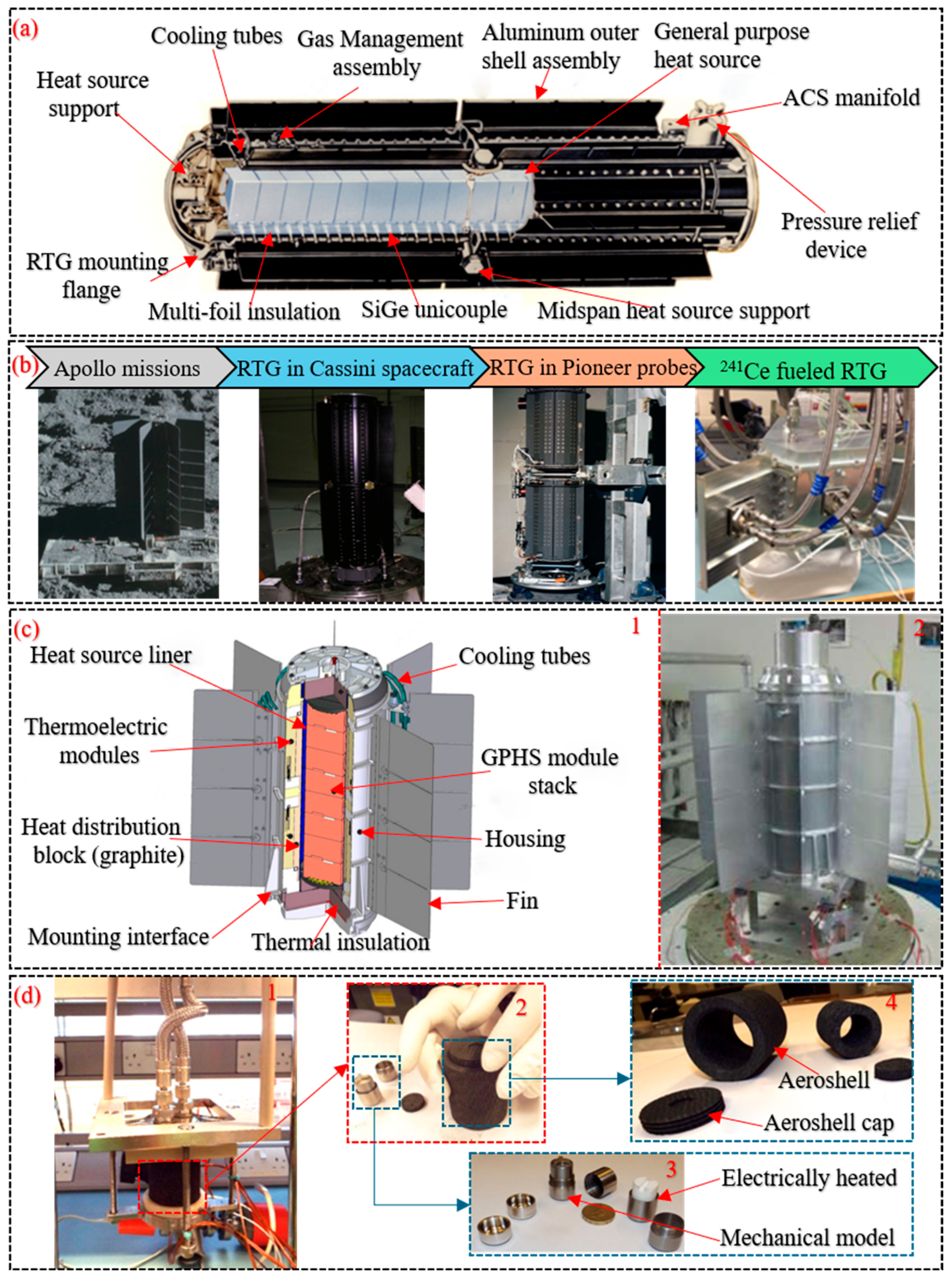
RTGs utilize the heat generated from the radioactive decay of isotopes to convert thermal energy into electrical power through the Seebeck effect in thermoelectric materials [
123]. As shown in
Figure 19a, a RTG primarily consists of GPHS modules, an array of thermocouples, a structural housing, cooling fins, and multilayer thermal insulation. RTGs typically employ
238Pu as their fuel source due to its emission of alpha particles during radioactive decay. These particles have a short absorption wavelength, generate high heat, and the isotope features a long half-life of 87 years while necessitating only minimal radiation shielding [
110]. Additionally, because RTGs contain no moving parts and the half-life of
238Pu fuel can be accurately predicted, they constitute a highly reliable nuclear power source capable of ensuring the long-term stable operation of space nuclear power system [
129].
Since its inception in the 1950s, the RTG has been widely employed to power space exploration vehicles, thereby driving the advancement of space missions [
133]. Since 1961, the NASA has launched a total of 45 RTG units in 26 distinct space exploration missions. These include the Apollo crewed lunar landings, the Voyager and Pioneer deep space probes, the Saturn-orbiting Cassini spacecraft, and the Mars Science Laboratory carrying the Curiosity rover [
133,
134,
135]. The RTG units installed on these spacecrafts are shown in
Figure 19b. The ESA has also successfully employed RTGs in multiple space exploration missions, including the deployment of the Huygens Probe to Saturn’s moon Titan and the Ulysses spacecraft [
136]. During the 1970s, the USSR deployed two lunar rovers equipped with polonium-based RTGs to survey the lunar surface environment [
137]. In 1996, Russia employed a penetrator fitted with an RTG for the Mars-96 exploration mission [
138]. In 2017, the NASA developed an advanced type of RTG under the Radioisotope Power System program. This device, designated as the Multi-Mission Radioisotope Thermoelectric Generator (MMRTG), is shown in
Figure 19c. The MMRTG is capable of generating an electrical output ranging from 100 to 125 W. It features a multilayer containment structure that effectively prevents the release of radioactive materials. Designed for maintenance-free operation over several decades, the MMRTG was deployed in NASA’s 2020 Mars exploration mission [
139]. In order to improve the conversion efficiency of radioisotope decay heat into electrical power, the U.S. Department of Energy, in collaboration with NASA, developed the advanced Stirling radioisotope generator. It incorporates two Stirling engines, each equipped with a GPHS module, which was engineered to deliver a minimum electrical output of 147 W [
84,
125].
In addition, the heat released by radioactive decay can be directly utilized through Radioisotope Heater Units (RHUs), which are employed to protect instruments and equipment from extreme cold temperatures. To date, the US has employed RHU devices in four exploration missions. The ESA has also designed and manufactured two RHU prototype units and is planning to initiate a flight testing program in 2025 [
140].
Figure 19d illustrates the testing of the RHU prototype units.
As previously mentioned, the lunar surface experiences extreme temperature fluctuations between day and night, along with the occurrence of lunar nights. As a result, certain energy storage and power generation technologies often fail to meet the operational requirements under such conditions. Following the successful deployment of RHUs during the Apollo 11 mission, RTGs were subsequently used in the Apollo 12 through Apollo 17 missions. To date, RTGs remain the only power systems that have successfully operated on the lunar surface while enduring the extreme environmental conditions of the lunar night [
141]. Over the past decade, the China Lunar Exploration Program has made steady progress. In 2013, China’s Chang’e-3 lander successfully landed on the lunar surface carrying a suite of RHUs (three 120-watt RHUs, one 8-watt RHU and one 4-watt RHU). In 2019, Chang’e-4 and its rover, Yutu-2, successfully touched down in the Von Kármán crater within the South Pole-Aitken basin [
142]. This mission represented the first spacecraft to soft-land on the lunar far side, as well as the first to utilize an RTG in this region, following the last application of an RTG on the Moon 47 years prior [
143]. The Chang’e-4 lander was equipped with a 120-watt-class RTG. This RTG serves two primary functions: (1) powering temperature sensors to measure lunar surface temperatures during lunar nights; (2) providing thermal insulation for instruments through its heat dissipation capability during nighttime operations [
29]. In addition, the ESA has developed a novel radioisotope power system that employs Cerium-241 (
241Ce) as fuel to supplement the existing
238Pu fuel-based systems [
144]. It has been demonstrated that, in addition to deep-space exploration missions, RTGs also satisfy the growing energy demands on the surfaces of the Moon.
Table 2 summarizes mission information involving the deployment of RTG or RHU devices on the lunar surface.
Table 2.
The deployment of RTG or RHU on the lunar surface [
10,
26,
27,
145].
Table 2.
The deployment of RTG or RHU on the lunar surface [
10,
26,
27,
145].
| Misson Name | Device | Usage of
RTG/RHU | Launch Time | Landing Site | Out Power |
|---|
| Apollo 12 |  | RTG | 1969 | 23.42° W,
3.01° S | 73.6 W |
| Luna 17 |  | RHU | 1970 | 35.1° W,
38.3° N | 1–2 W |
| Apollo 14 |  | RTG | 1971 | 17.47° W,
3.65° S | 73 W |
| Apollo 15 |  | RTG | 1971 | 3.63° E,
26.13° N | 74.7 W |
| Apollo 16 |  | RTG | 1972 | 15.5° E,
8.97° S | 70.9 W |
| Apollo 17 |  | RTG | 1972 | 30.77° E,
20.19° N | 75.4 W |
| Luna 21 |  | RHU | 1973 | 38°18′ W,
25°58′ N | 1–2 W |
| Chang’E-3 |  | RHU | 2013 | 19.5° W,
44.1° N | 390 W |
| Chang’E-4 |  | RHU and
RTG | 2018 | 177.59° E,
45.46° S | 3.2–3.5 W |
Figure 19.
Radioisotope power systems. (
a) Schematic diagram of RTG structure [
105]. (
b) RTG implementations in space probes [
146]. (
c) MMRTG: 1—Structural schematic; 2—Prototype for Mars exploration missions [
139]. (
d) RHU: 1—Testing under simulated vacuum conditions; 2—Heat source module; 3—Heat source; 4—Gas shell [
140].
Figure 19.
Radioisotope power systems. (
a) Schematic diagram of RTG structure [
105]. (
b) RTG implementations in space probes [
146]. (
c) MMRTG: 1—Structural schematic; 2—Prototype for Mars exploration missions [
139]. (
d) RHU: 1—Testing under simulated vacuum conditions; 2—Heat source module; 3—Heat source; 4—Gas shell [
140].
4.1.2. Nuclear Fission Reactor Power System
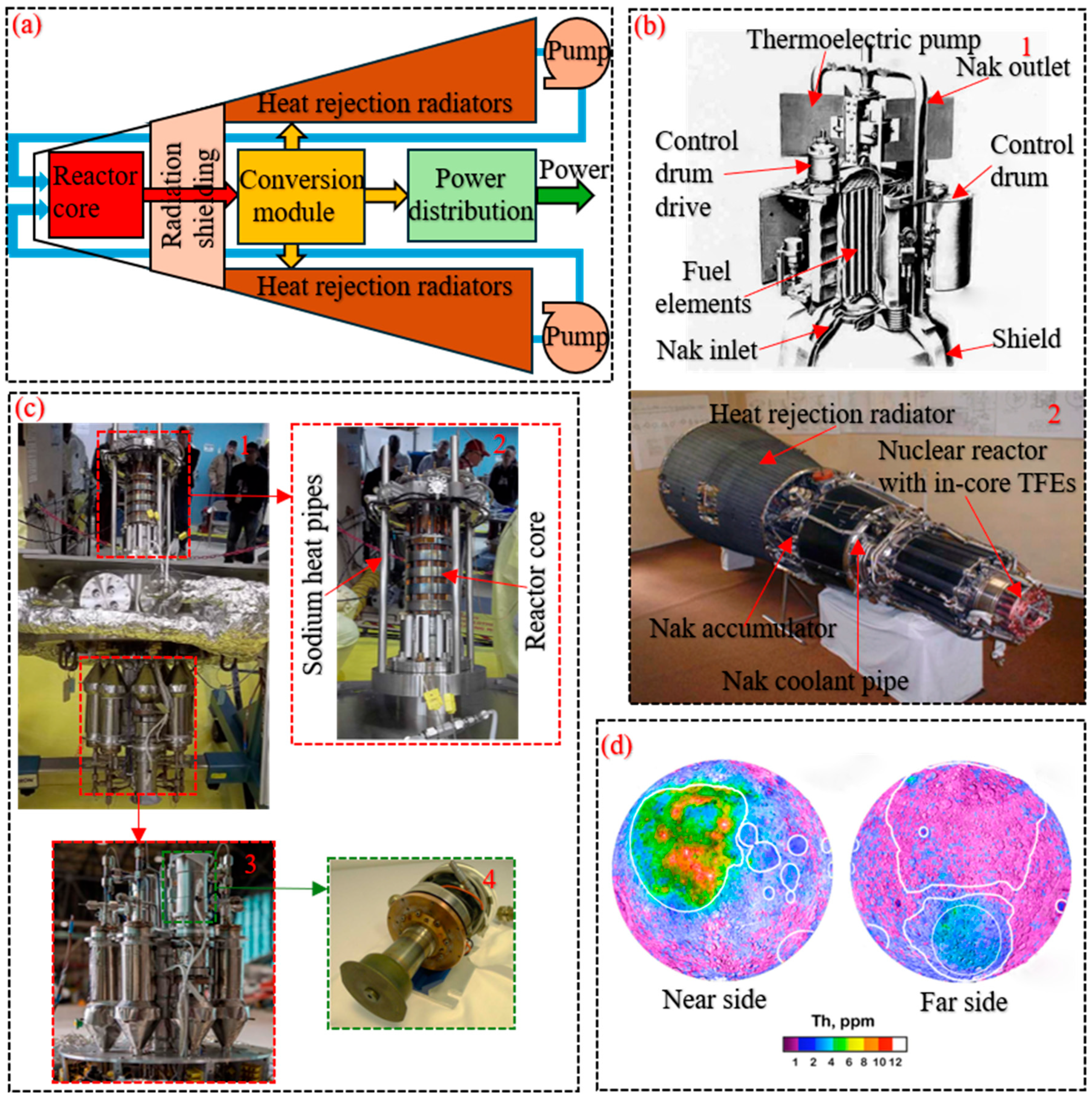
With the deepening of human space exploration, the demands placed on power sources have correspondingly increased. A space-based nuclear fission reactor power system produces electricity through controlled nuclear fission reactions; it offers a long operational lifespan and excellent environmental adaptability, and is primarily used to supply power to spacecraft [
147]. As illustrated in
Figure 20a, the system is composed of a reactor core, radiation shielding, a thermoelectric conversion module, a heat rejection subsystem, and a power distribution unit.
In a nuclear fission reactor power system, the thermal energy generated from continuous fission reactions within the reactor core is delivered to the thermoelectric conversion module, where the majority is transformed into electrical power. The residual heat is subsequently released into space through the heat rejection subsystem [
148]. To ensure extended operation under high thermal conditions, the reactor core is generally maintained within a temperature range of 900 to 1500 K, which is optimized to enhance the system’s overall thermodynamic performance [
149]. The reactor’s thermoelectric conversion system primarily consists of static systems, such as thermoelectric systems or thermionic systems, and dynamic engines, such as Brayton engines, Rankine engines, and Stirling engines. Similar to the reactor core, these components are required to operate at high temperatures for tens of thousands of hours [
150]. Due to the strong penetrative capability of photons, gamma rays produced by fission reactions are difficult to attenuate; necessitating robust radiation shielding. Using low atomic mass elements as shielding materials is highly effective; for terrestrial nuclear reactors, materials such as concrete and water are commonly employed for neutron shielding [
151]. Lithium hydride is considered one of the most efficient neutron shielding materials, owing to its low density and rich hydrogen composition, and was utilized in the SNAP space reactor program. Besides lithium hydride, other materials such as zirconium hydride, titanium hydride, graphite foam hydride, and lithium–magnesium alloys can also be employed as shielding materials [
152].
In April 1965, US successfully launched the first space nuclear fission reactor power system, SNAP-10A (
Figure 20(b1)), ushering in an era of nuclear energy utilization in space by nations worldwide [
130]. Between 1970 and 1988, the USSR developed four models of space reactor power systems—Romashka, BUK, TOPAZ-I, and TOPAZ-II—and launched 34 military reconnaissance satellites, of which 32 were powered by the BUK system and two by the TOPAZ-I system. The BUK system employed a uranium–molybdenum fast reactor and a two-stage silicon-germanium tandem thermoelectric conversion unit, achieving a power output of 3 kW. The TOPAZ-I system employed a uranium dioxide thermal reactor cooled by a NaK liquid–metal alloy, with a generated electrical power output of 6 kW [
153]. The prototype of the TOPAZ-I reactor power unit is shown in
Figure 20(b2). In 1983, the U.S. Defense Initiative Organization [
154] launched the SP-100 space nuclear reactor program, aiming to develop a 100 kilowatt-class space power system.
In the 21st century, the US successively implemented the Prometheus Program and the Kilowatt-Class Space Nuclear Fission Power Reactor Program. Under the Prometheus Program, the reactor power system employed a gas-cooled fast reactor integrated with a Brayton-cycle power conversion unit. The reactor’s thermal power was megawatt-class, with a target electrical output of 200 kW to propel spacecraft [
155]. In 2018, NASA completed the hardware testing of the KSNFPR program, with the prototype reactor depicted in
Figure 20c. The reactor employs solid-metal uranium as the reactor core, and its thermoelectric conversion system comprises eight 125-watt advanced Stirling engines. This reactor can generate an electrical output of 1 to 3 kW, making it suitable as a power source for lunar surface construction activities [
156]. In 2009, Russia announced to develop a nuclear-powered spacecraft with megawatt-level capacity, with plans to conduct an in-orbit flight test by 2025. The proposed spacecraft incorporates a nuclear reactor-driven power system that combines a gas-cooled fast reactor with a Brayton cycle power conversion unit to supply energy for electric propulsion in crewed deep space missions [
157].
Since uranium-235 (
235U) is non-radioactive and does not generate heat during the manufacturing and launch phases, it is currently used as the core material in all space nuclear reactors [
158]. On Earth, the
235U fuel cores employed in nuclear reactors can be sourced from decommissioned nuclear weapons. On the Moon, the lunar regolith contains a fuel known as thorium, which can be converted into uranium-233 (
233U) fuel suitable for nuclear fission reactions through neutron bombardment. Nuclear reactors utilizing
233U cores offer enhanced safety compared to current
235U-based reactors on Earth and produce fewer byproducts during operation [
159]. In 2021, Bruhaug and Phillips [
160] analyzed nuclear fuel resources on the Moon employing a gamma-ray spectrometer aboard the Prospector spacecraft. Their findings revealed that fissile materials, specifically uranium and thorium, are predominant and possess the potential for extraction in quantities reaching billions of tons.
Figure 20d presents a surface map of thorium concentration on the Moon. These findings indicate that the lunar surface contains abundant raw materials suitable for nuclear fission reactions, suggesting that space nuclear fission reactor power system have a certain degree of feasibility for sustained operation on the Moon. Such systems could provide a reliable energy supply for various lunar infrastructure and development activities.
Figure 20.
Space-based nuclear fission power systems. (
a) Schematic of the primary reactor components. (
b) Early space nuclear fission reactor system prototypes: 1—SNAP-10A; 2—TOPAZ. (
c) Kilowatt-class nuclear fission reactor equipped with Stirling engines: 1—Assembled reactor; 2—Reactor core assembly; 3—Thermoelectric conversion unit; 4—advanced Stirling engines [
131]. (
d) Global distribution map of thorium concentration on the lunar near and far sides [
161].
Figure 20.
Space-based nuclear fission power systems. (
a) Schematic of the primary reactor components. (
b) Early space nuclear fission reactor system prototypes: 1—SNAP-10A; 2—TOPAZ. (
c) Kilowatt-class nuclear fission reactor equipped with Stirling engines: 1—Assembled reactor; 2—Reactor core assembly; 3—Thermoelectric conversion unit; 4—advanced Stirling engines [
131]. (
d) Global distribution map of thorium concentration on the lunar near and far sides [
161].
4.2. Nuclear Fusion Technology
Compared with other energy generation methods, nuclear fusion technology offers several advantages: it is capable of producing electrical power with an exceptionally high power density, relies on abundant renewable fuel sources, and emits no greenhouse gases or other pollutants during operation [
162]. Consequently, although nuclear fusion technology entails numerous physical and engineering complexities, it has long been a major objective of humanity. Research into its realization began in the 1930s. By the 1950s, the first Earth-based devices designed to simulate fusion reactions were constructed, and research in nuclear fusion technology has since progressed steadily [
163].
4.2.1. Principle of Nuclear Fusion Technology
Nuclear fusion refers to the process whereby light atomic nuclei merge under certain conditions (extremely high temperatures and pressures), combine to form a new, heavier nucleus and release a tremendous amount of energy [
161]. The process is shown in
Figure 21a. The most extensively investigated fusion reactions involve plasmas consisting of hydrogen isotopes—deuterium (D) and tritium (T)—
3He, or boron-11 (
11B) as reactants, with the reaction equations as follows:
Figure 21b illustrates how the fusion reaction cross section varies with particle energy. Maintaining sustained nuclear fusion requires that the reactant nuclei exist in a plasma state [
164]. The plasma state represents the phase in which fusion fuel is confined within a fusion device; more specifically, plasma is defined as a fully or partially ionized gas. By heating a gas to sufficiently high temperatures, the particles’ average kinetic energy becomes comparable to the ionization energy, thereby producing a mixture of electrons and ions. A clear relationship exists between the particles’ average kinetic energy
and the system temperature (
, expressed as:
where
denotes the Boltzmann constant. In a plasma, temperature is commonly measured in electron volts (eV), a unit representing high-energy scales, and the two principal parameters of a plasma are particle density and temperature [
165].
In fusion reactions, the plasma exhibits a particle density of approximately 10
20 m
−3 under magnetic confinement and about 10
31 m
−3 under inertial confinement [
166]. Among these fusion reactions, the D–T reaction is the current primary research focus; to initiate D–T fusion, the fuel particles must be heated to 25 keV. Moreover, sustaining the fusion reaction requires sufficient confinement energy—the constraints on pressure (
) and temperature (
) are given by the Lawson Criterion:
where
represents a constant associated with alpha-particle heating power;
and
correspond to constants related to radiative and conductive energy losses, respectively; and
denotes the energy confinement time [
167]. Currently, there are two confinement methods: Magnetic Confinement Fusion (MCF) and Inertial Confinement Fusion (ICF). Below is a brief introduction to these two methods.
In MCF, high-energy plasma is confined by a strong magnetic field, utilizing the plasma’s electrical conductivity. The magnetic field constrains the plasma radially but allows particles to escape through the ends of a solenoid. To prevent this escape, large volumes of high-temperature plasma are confined in a toroidal region by a strong magnetic field in a tokamak device. The operating principle is illustrated in
Figure 21c, and this approach is widely adopted in MCF systems [
168]. In ICF, fusion reactions are initiated by the rapid heating and compression of a fuel pellet using intense laser pulses over a very short timescale. The fuel pellet typically consists of a D–T mixture. Due to its mass inertia, the fuel cannot expand quickly, thereby achieving confinement of the fusion reaction [
169]. A schematic of the ignition device used in this process is shown in
Figure 21d.
Figure 21.
Technical principles of nuclear fusion reactions. (
a) Schematic diagram of the nuclear fusion reaction process. (
b) Cross-section versus energy relationship curve from fusion reaction experiments [
166]. (
c) Working principle of the Tokamak device. (
d) Schematic diagram of the laser ignition target [
170].
Figure 21.
Technical principles of nuclear fusion reactions. (
a) Schematic diagram of the nuclear fusion reaction process. (
b) Cross-section versus energy relationship curve from fusion reaction experiments [
166]. (
c) Working principle of the Tokamak device. (
d) Schematic diagram of the laser ignition target [
170].
4.2.2. Development Progress of Nuclear Fusion Technology
Nuclear fusion technology is primarily utilized for energy generation, wherein the thermal energy produced by fusion reactions serves as a source for electricity production. The concept of a fusion power plant was initially proposed in the 1960s through collaborative efforts by researchers from Europe, the US, and the USSR [
171]. Such a power plant functions based on the operating principles of a nuclear fusion reactor. A stoichiometric D–T mixture is encapsulated within a vacuum chamber and heated by high-intensity lasers to approximately 150 million K to form plasma. The resulting plasma is magnetically confined to prevent direct interaction with the reactor vessel. Under these extreme temperature and pressure conditions, D and T nuclei undergo fusion reactions, producing helium and free neutrons while releasing substantial kinetic energy [
172].
Figure 22(a1) illustrates the reactor assembly within a fusion power plant.
The Joint European Torus (JET) [
173] located in the United Kingdom, began operation in 1983 as the world’s largest tokamak reactor at that time (
Figure 22(a2)). In 1991, JET produced the first plasma capable of generating net energy, reaching a reactor power output of 1.8 MW. In 2005, the project site for the International Thermonuclear Experimental Reactor (ITER) was established at Cadarashe, France, and by 2007 preliminary reactor (
Figure 22(a3)) operations had begun. ITER is intended to demonstrate nuclear fusion at a larger power scale and to achieve a self-sustaining (ignited) plasma reaction [
174]. In 2017, the European Union proposed the Demonstration Fusion Power Plant (DEMO) project [
175], leveraging the testing experience gained from the ITER project and employing a reactor with a closed fuel cycle, as illustrated in
Figure 22(a4). The primary goal of DEMO is to construct the first fusion power system capable of supplying electricity to the grid, with a projected net electrical output ranging from 300 to 500 MW. In December 2022, Lawrence Livermore National Laboratory (LLNL) in California reported a major advancement in fusion experimentation. The laboratory successfully achieved a net energy gain from a nuclear fusion reaction for the first time, using 2.1 MJ of input energy to drive high-intensity lasers and generating 2.5 MJ of fusion output [
176]. In July 2023, LLNL attained net energy output again; in this laser-driven fusion experiment, 2 MJ of input energy was used to initiate the reaction, yielding 3.15 MJ of fusion output, significantly enhancing the energy gain ratio [
177]. Nuclear fusion technology is deemed feasible for energy production. At present, over 38 private enterprises are actively exploring novel fusion pathways with the objective of realizing commercial fusion power within the coming decades [
178].
Figure 22b presents recent advancements in fusion research. The technology is progressing rapidly, accelerating the transition toward the deployment of this promising clean energy source.
Fusion technology offers considerable promise for future space propulsion systems. Due to the relatively limited power output of nuclear fission reactors, they are increasingly considered inadequate for deep-space missions, especially those targeting destinations beyond Mars or extending beyond the solar system. In contrast, fusion reactors are expected to become the primary energy systems supporting long-duration deep-space missions in the future [
179]. In the 1950s, nuclear fusion propulsion systems were first proposed in the Falcon Project, and subsequently appeared multiple times in NASA innovative advanced concepts program [
180]. The NASA Glenn Research Center (GRC) designed an MCF-based nuclear-propulsion spacecraft [
181], designated Discoverer 2. Its configuration is shown in
Figure 22c. The spacecraft is intended for missions to Jupiter or Saturn, with a flight duration of less than one year and a payload fraction exceeding 5%. In 2010, NASA’s Marshall Space Flight Center Advanced Concepts Office proposed a Z-pinch fusion approach utilizing Magnetized Target Fusion, intended for integration into a reusable spacecraft designed for human missions to Mars [
182].
Figure 22.
Development of nuclear fusion technology. (
a) Tokamak devices employed in various nuclear fusion missions [
172]. (
b) Research achievements in nuclear fusion technology: 1—Number of published scientific works; 2—Number of fusion enterprises established [
178]. (
c) Configuration of Discoverer 2: 1—Overall structure; 2—Nuclear propulsion system [
182].
Figure 22.
Development of nuclear fusion technology. (
a) Tokamak devices employed in various nuclear fusion missions [
172]. (
b) Research achievements in nuclear fusion technology: 1—Number of published scientific works; 2—Number of fusion enterprises established [
178]. (
c) Configuration of Discoverer 2: 1—Overall structure; 2—Nuclear propulsion system [
182].
Although fusion energy has not yet been applied in current deep space exploration missions, research in this field has never ceased. Beyond these closed onboard fusion propulsion concepts, another line of research has explored open-cycle propulsion architectures that attempt to utilize the surrounding space medium. A representative example is the Bussard-type propulsion system, originally proposed by Bussard in 1960, which aims to employ large-scale electromagnetic fields to collect dilute matter from the surrounding interstellar or interplanetary medium and subsequently use it as fusion fuel and/or reaction mass [
183]. In principle, such a concept offers a possible pathway toward reducing the dependence of spacecraft on stored propellant and extending mission endurance [
184]. Although this type of system is not directly applicable to lunar surface power generation, it is relevant to the broader framework of space energy infrastructure because it reflects an integrated utilization of energy conversion, plasma propulsion, and active interaction with the ambient space environment. Recent studies have further suggested that related open-type plasma systems may be of interest for orbital transfer vehicles and other advanced in-space transportation scenarios [
185]. However, the practical realization of Bussard-type propulsion remains highly challenging due to the extremely low density of the ambient medium, the enormous electromagnetic collection scale required, severe drag and radiation losses, and the difficulty of achieving efficient and sustained fusion under realistic operating conditions [
186]. Compared with these highly exploratory open-cycle propulsion concepts, the utilization of
3He resources on the Moon represents a more resource-oriented and energy-supply-related pathway within the broader fusion framework.
4.2.3. Prospect of 3He Nuclear Fusion
The 3He isotope can also serve as fusion fuel; it can undergo the D–3He fusion reaction with deuterium or the 3He–3He fusion reaction with itself. The specific reaction equations are given by Equations (14) and (16).
3He is considered a clean, safe, and controllable fuel for nuclear fusion. In contrast to conventional fusion reactions involving tritium,
3He fusion does not produce high-energy neutrons that could damage the reactor, nor does it involve radioactive reactor materials; thereby eliminating the emission of hazardous radiation into the environment [
187]. The majority of energy produced through
3He fusion is carried by positively charged particles—namely protons and nuclei—which enables direct conversion into electrical power, bypassing traditional intermediate energy transformation stages. This reaction has been confined under experimental conditions using inertial electrostatic confinement [
188].
3He is generated via nuclear fusion processes within the Sun’s core and is subsequently transported through space in an ionized form by the solar wind. As it approaches Earth, these charged helium nuclei are deflected by the planet’s magnetic field, preventing their entry into the atmosphere. The primary sources of
3He on Earth include the decay of tritium and trace amounts found in gases originating from mantle-derived channels, such as those released by the Kilauea Volcano in Hawaii [
189]. Consequently, terrestrial
3He resources are limited. Estimates suggest that the Earth’s atmosphere contains roughly 4 × 10
6 kg of
3He, while the mantle holds about 10
9 kg [
190]. Due to the scarcity of
3He,
3He fusion cannot provide a sufficient energy supply for Earth.
In contrast, the Moon has virtually no magnetic field or atmosphere, allowing solar wind particles to strike the lunar surface directly, implanting helium and other solar wind species into the lunar regolith. During the Apollo 11 exploration mission, it was discovered that in the Mare Tranquillitatis region, at depths reaching up to 3 m and across an area of approximately 2 square kilometers, the amount of
3He was about 100 kg. This finding confirmed that
3He particles do indeed accumulate within the lunar regolith [
191]. Drawing on data from nine Apollo lunar regolith samples, Johnson et al. [
63] empirically established a positive linear correlation among
3He content in the lunar regolith, titanium dioxide (TiO
2) content, and regolith maturity, as illustrated in
Figure 23(a1). They also provided a preliminary assessment of the
3He distribution within the uppermost 1 µm layer of lunar surface regolith, as illustrated in
Figure 23(a2). In 1991, Wittenberg et al. [
187] estimated the total mass of
3He in the lunar regolith to be approximately 10
9 kg. By 1994, Taylor et al. [
192] revised this estimate, calculating the total
3He content in the regolith to be approximately 7.15 × 10
8 kg.
The previous estimations did not incorporate the influence of solar wind flux and were limited to the assessment of
3He distribution within the top 1 μm layer of lunar regolith. To improve the accuracy of calculating the total
3He content and its spatial distribution, Fa and Jin [
193] proposed a predictive model that utilizes surface Optical Maturity (OMAT) data obtained from Clementine Ultraviolet/Visible (UV/VIS) multispectral observations. This model enables calculation of the monthly average solar wind flux at any specified point on the lunar surface, as expressed by:
Here,
and
correspond to the longitude and latitude, respectively, of a specific location on the lunar surface;
represents the uniform solar wind flux within the solar system, while
denotes the proportion of each lunar phase during which the Moon is fully obscured by Earth’s magnetotail.
Figure 23(b1) illustrates the spatial distribution of normalized solar wind flux across the lunar surface. As a result of varying solar wind incidence angles, the flux intensity diminishes progressively with increasing latitude.
The formula for calculating the OMAT of the regolith surface was proposed by Lucey et al. [
194], and is expressed as follows:
where R denotes reflectance, and the subscripts indicate the corresponding wavelengths. The constants are given as
= 0.08 and
= 1.19, the distribution of OMAT over the lunar surface is shown in
Figure 23(b2). It can be seen that the locations with high OMAT are places with immature fresh craters and their rays. The TiO
2 content in the regolith can be expressed as [
194]:
where
= 0.0 and
= 0.42.
Figure 23(b3) presents the spatial distribution of TiO
2 across the lunar surface, derived from Clementine UV/VIS multispectral data and calculated using Equation (21). The final analysis revealed a correlation coefficient of 0.944 between
3He concentration and three key parameters: TiO
2 content, solar wind flux, and regolith maturity. Based on measurements of regolith thickness conducted by the Chang’e-1 mission, Fa and Jin [
193] quantitatively estimated the global reserve of
3He in the lunar regolith to be approximately 6.6 × 10
8 kg. Based on the dataset provided by Fa et al., Kim et al. [
195] constructed a global map illustrating the spatial distribution of
3He within the lunar surface regolith, as illustrated in
Figure 23c.
Wittenberg et al. [
187] were the earliest to propose the use of lunar
3He resources as fuel for nuclear fusion. Subsequently, Gerald et al. [
196] examined the practicality of harvesting
3He from the Moon for application in D–
3He fusion reactor systems. While the spatial distribution of
3He within the lunar regolith can be quantitatively assessed, extracting adequate amounts of
3He would necessitate the deployment of mining infrastructure capable of handling substantial regolith volumes through well-engineered extraction techniques, processing systems, and equipment [
161]. In conclusion, the implementation of
3He-based fusion technology on the lunar surface remains a long-term prospect, potentially requiring several decades—or even centuries—to achieve.
Figure 23.
3He resources on the Moon. (
a) Initial hypotheses regarding
3He distribution across the lunar surface: 1—Distribution of
3He within the top 1 μm layer of lunar regolith; 2—Empirical linear correlation between
3He content in the regolith and parameters [
63]. (
b) Spatial distribution maps of selected parameters on the lunar surface: 1—Distribution of normalized solar wind flux; 2—Distribution of OMAT; 3—Distribution of TiO
2 content [
193]. (
c) Lunar surface distribution map of
3He content inferred from Clementine-based TiO
2 and OMAT datasets [
195].
Figure 23.
3He resources on the Moon. (
a) Initial hypotheses regarding
3He distribution across the lunar surface: 1—Distribution of
3He within the top 1 μm layer of lunar regolith; 2—Empirical linear correlation between
3He content in the regolith and parameters [
63]. (
b) Spatial distribution maps of selected parameters on the lunar surface: 1—Distribution of normalized solar wind flux; 2—Distribution of OMAT; 3—Distribution of TiO
2 content [
193]. (
c) Lunar surface distribution map of
3He content inferred from Clementine-based TiO
2 and OMAT datasets [
195].
5. Application of Chemical Batteries in Space Energy Systems
In addition to the three primary energy sources discussed above, several energy storage devices can also be utilized in space exploration missions, including batteries and fuel cells. The following section will briefly introduce the working mechanisms of these two types of devices, along with their respective applications in space exploration.
5.1. Batteries
Batteries are electrochemical devices that store electrical energy by converting it into chemical energy. In contrast to fuel cells, secondary (rechargeable) batteries offer the advantage of being recharged and discharged multiple times. During charging, energy is stored via reversible chemical reactions and subsequently released during discharge when power is required. The energy conversion efficiency of batteries typically exceeds 70%. However, their storage capacity tends to degrade with increasing charge–discharge cycles, making them more suitable for energy storage and short-term power supply applications [
197].
5.1.1. Operating Principle of Batteries
Energy conversion and storage in batteries occur through electrochemical reactions. During discharge, batteries deliver electrical power to an external load, whereas during charging, they absorb electrical energy and convert it into stored chemical energy. A battery typically comprises the following major components: anode, cathode, current collector, electrolyte, and separator [
198]. The corresponding charge and discharge processes are illustrated in
Figure 24.
The electrodes of a battery are typically fabricated from different materials, endowing them with distinct electrochemical properties. The electrolyte is a conductive medium that permits only ionic conduction, while the separator between the electrodes allows ions to pass but blocks electrons. This configuration prevents internal short circuits and ensures that charge transfer occurs exclusively via ionic conduction [
199]. During discharge, the anode’s active material undergoes an oxidation reaction, releasing electrons and generating cations. These electrons travel through the external circuit toward the cathode, where the cathode’s active material accepts the electrons and participates in a reduction reaction with the cations present in the electrolyte, forming new compounds. In the external circuit, electrons move from the anode to the cathode, generating a current that drives the load [
200]. During charging, an external power source applies a voltage to the battery, driving electrons to flow in reverse—from the cathode to the anode. At the anode, the active material receives these electrons and is restored through interaction with ions extracted from the electrolyte, storing these ions within the anode. Concurrently, at the cathode, an oxidation reaction liberates the ions previously stored there, which then migrate through the electrolyte toward the anode [
201].
Secondary batteries can be classified by their internal chemical composition into seven types: Lead–Acid Batteries (LABs), Nickel–Metal Hydride Batteries (NMHBs), Nickel–Cadmium Batteries (NCBs), Lithium–Ion Batteries (LIBs), Lithium Polymer Batteries (LPBs), Sodium–Sulfur Batteries (NSBs), and Solid–State Batteries (SSBs) [
202]. LABs are composed of a porous lead anode, a lead dioxide cathode, and a sulfuric acid electrolyte. These batteries are known for their structural durability and low manufacturing cost. However, their inherent lead composition results in limitations such as reduced cycle life, relatively low energy density, and considerable weight [
203]. NMHBs typically employ hydrogen-absorbing alloys of lanthanum, cerium, neodymium, and manganese as the anode material, nickel oxyhydroxide as the cathode material, and an alkaline potassium hydroxide solution as the electrolyte. These batteries offer a power density ranging from 250 to 1000 W/kg and support 500 to 1000 charge–discharge cycles. Their very low internal resistance provides performance benefits; however, they are subject to a relatively high self-discharge rate of approximately 30% per month [
204]. NCBs employ cadmium as the cathode material and nickel hydroxide (NiOH) as the anode material, while an alkaline potassium hydroxide solution functions as the electrolyte. NCBs exhibit excellent stability, but their drawbacks include relatively low energy density, elevated production cost, and restricted cycle life [
205]. LIBs typically employ lithium titanate as the anode and lithium metal oxides as the cathode, using a non-aqueous carbonate electrolyte mixture containing lithium–ion complexes: such as lithium hexafluorophosphate. LIBs exhibit a specific energy density of approximately 250 Wh/kg, and can sustain several thousand charge–discharge cycles [
206]. NSBs utilize molten sodium as the anode material, enclosed within a sodium–alumina ceramic tube, while molten sulfur, arranged in a surrounding annulus, serves as the cathode. A β-alumina ceramic, which conducts sodium ions, is employed as the electrolyte. NSBs offer advantages such as long cycle life, high cost-effectiveness, minimal on-site maintenance, and environmental friendliness [
207]. SSBs use anode and cathode materials similar to those in conventional batteries, but differ in that they utilize a solid-state electrolyte. SSBs offer advantages such as compact size, lightweight design, increased energy output, and improved ionic transport. However, they also face limitations, including relatively low specific power, higher ionic resistance, and elevated manufacturing costs [
208]. The oxidation-reduction reactions occurring at the electrodes of the aforementioned batteries, along with their respective application scenarios, are summarized in
Table 3.
5.1.2. Space Applications of Batteries
During the initial phases of space exploration, batteries played a vital role in spacecraft, as most electronic systems and scientific instruments depended on the stored electrical energy within them. Primary batteries used in space missions have included silver–zinc (Ag–Zn), lithium–sulfur dioxide (Li–SO
2), and lithium-thionyl chloride (Li–SOCl
2) batteries. Secondary batteries used in space missions have encompassed Ag–Zn, nickel–cadmium (Ni–Cd), nickel–hydrogen (Ni–H
2), and lithium–ion (Li–ion) batteries. Considering battery performance characteristics, secondary batteries currently hold greater potential for application in space compared to primary batteries [
69].
Among secondary batteries, Ag–Zn batteries are well-suited for short-term space exploration activities, providing power to extravehicular maneuvering units on launch vehicles. Ni–Cd batteries, with their long cycle life, are typically employed in various orbital spacecraft, such as those powering geostationary satellites. Ni–H
2 batteries offer performance comparable to Ni–Cd batteries but exhibit a longer cycle life under the same discharge power; for space missions with discharge power exceeding 1 kW, Ni–H
2 batteries have supplanted Ni–Cd batteries. Li–ion batteries, characterized by their compact structure, lightweight design, and high specific energy and power density, have been widely utilized in Earth-orbit spacecraft, planetary landers, and rovers [
209]. Advancements in Li–ion battery technology are pivotal to expanding battery applications in space environments. In particular, alloy-based anode materials (silicon, germanium, tin) can significantly enhance battery energy density, thereby reducing launch payloads and lowering costs.
The Ag–Zn battery system was the first type of battery to be used in space missions. In 1956, the Soviet Union’s Sputnik 1 spacecraft, and in 1962, the US Ranger 3, Mariner 2, and Mariner 4 spacecraft were all equipped with Ag–Zn battery systems [
210]. In 1959, Ni–Cd batteries were used for the first time as a space power source aboard Explorer 6, although the system operated for only three months. In 1960, NASA launched TIROS I, the first low Earth orbit meteorological satellite equipped with Ni–Cd batteries capable of long-term operation. Subsequently, Ni–Cd batteries were employed in missions such as Solar Maximum Mission and Landsat D [
211]. The first application of Ni–H
2 batteries was on the US Navy’s NTS-2 spacecraft, where they served as backup power for Ni–Cd batteries. In 1983, Ni–H
2 batteries were formally deployed on the Intelsat V satellite. Due to their significantly longer cycle life, Ni-H
2 batteries were subsequently integrated into the majority of geostationary satellites and also used in the Hubble Space Telescope, launched in 1990 [
212].
Figure 25 illustrates space exploration probes equipped with battery systems.
The primary lithium batteries used in space applications are Li–SO
2 batteries and Li–SOCl
2 batteries. Li–SO
2 batteries have been used in planetary probes such as Galileo, Cassini, Genesis, and various Mars landers. Li–SOCl
2 batteries have provided power for the Sojourner Mars rover, launch vehicles, and the Philae lander [
213]. Li–ion secondary batteries are considered the preferred energy storage solution for space missions where stringent constraints on mass and volume exist, and moderate cycle life is deemed acceptable. Since their initial application in the Mars lander launched in 2001, Li–ion batteries have been widely adopted in various space programs, including China’s Chang’e lunar exploration program, the U.S. Mars colonization initiatives, and the International Space Station (ISS) [
214]. Space missions utilizing battery systems are summarized in
Table 4. As can be observed, secondary batteries—such as Ag–Zn, Ni–Cd, Ni–H
2, and Li–ion have seen increasing utilization in space missions.
5.2. Fuel Cells
A fuel cell is an electrochemical device that converts the chemical energy stored in a fuel directly into electrical energy. Owing to their high energy conversion efficiency, low environmental impact, quiet operation, adaptability to different fuel sources, and wide range of power capacities, fuel cells are widely utilized in a variety of application fields [
216].
5.2.1. Operating Principle of Fuel Cells
Fuel cells utilize oxygen and hydrogen as fuels to generate electricity through electrochemical reactions, with water and heat produced as byproducts. In addition, the energy conversion efficiency of fuel cells generally falls within the range of 40 to 60%. A typical fuel cell comprises three essential functional components: the fuel electrode (anode), the oxidant electrode (cathode), and an electrolyte layer situated between them. Both electrodes are made of porous materials and are coated with a catalytic layer [
217,
218]. The operating principle of the fuel cell is illustrated schematically in
Figure 26. Molecular hydrogen is delivered to the anode via a gas flow, where it is oxidized, generating hydrogen ions and releasing electrons. The corresponding reaction is as follows:
Hydrogen ions migrate through the acidic electrolyte, while electrons are forced to travel through an external circuit and eventually reach the cathode. At the cathode, the electrons and hydrogen ions react with oxygen from the external gas flow to produce water. The corresponding reaction is as follows:
The net electrochemical reaction occurring in a fuel cell produces water, thermal energy, and electricity. This reaction can be expressed as:
Conversely, the reverse reaction in a Regenerative Fuel Cell (RFC) involves the electrolysis of water, producing hydrogen and oxygen gases. These generated gases can subsequently be recycled as reactants in the fuel cell for power generation [
219]. The corresponding reaction is as follows:
Based on the properties of their fuel and electrolyte components, fuel cells are generally classified into six main types: Phosphoric Acid Fuel Cell (PAFC), Proton Exchange Membrane Fuel Cell (PEMFC), Direct Methanol Fuel Cell (DMFC), Alkaline Fuel Cell (AFC), Molten Carbonate Fuel Cell (MCFC), and Solid Oxide Fuel Cell (SOFC) [
220]. PEMFCs possess numerous advantages, including high power density, fast start-up capability, low operating temperatures, and operational simplicity, making them the most widely used type in the transportation sector. DMFCs, an extension of PEMFCs, are characterized by long service life and rapid power generation capability, which make them well-suited for use as portable power sources [
221]. AFCs exhibit optimal performance under conditions utilizing pure hydrogen and oxygen. However, their pronounced sensitivity to contaminants—especially carbon oxides—and limited operational lifespan have constrained their widespread adoption in terrestrial applications. Consequently, AFCs are primarily employed in space [
222]. PAFCs represent the most commercially advanced category among medium-temperature fuel cells and are known for their relatively high energy conversion efficiency. They are frequently employed in combined heat and power applications. MCFCs and SOFCs, both operating at elevated temperatures, are particularly suitable for use in combined heat and power systems as well as in integrated combined-cycle power generation configurations. Furthermore, as high-temperature electrochemical energy conversion devices, MCFCs and SOFCs exhibit excellent fuel flexibility. They can operate on hydrocarbon-based fuels, including natural gas, biogas, syngas, and certain liquid hydrocarbons, thus overcoming the strict reliance on pure hydrogen [
223]. For instance, a solid oxide electrolyzer cell was successfully employed by NASA in the MOXIE project to split Martian CO
2 into CO and O
2. Operating at approximately 800 °C, the SOEC utilizes its oxygen-ion selective conduction characteristics, enabling the transmembrane migration of oxygen ions through a stabilized zirconia ceramic electrolyte, while utilizing nickel-based electrodes to promote the electrochemical decomposition of CO
2 [
224]. The electrochemical reactions and potential application scenarios of the aforementioned fuel cells are summarized in
Table 5.
5.2.2. Space Applications of Fuel Cells
As previously mentioned, the high energy density of fuel cells has enabled their integration into distributed power systems for vehicles such as buses, automobiles, and aircraft. Additionally, they have been employed across a range of power generation scenarios, including portable, stationary, and decentralized energy applications. Fuel cells are also well-suited for space power supply, and the ambient gas composition in space does not adversely affect the performance of PEMFCs or AFCs. However, traditional space fuel cells rely on stored fuel and oxidants; once the substances in the tanks are exhausted, they can no longer provide power [
227].
In contrast, RFCs generate electrical energy through electrochemical reactions while also using an external power source to perform water electrolysis, thereby replenishing the hydrogen and oxygen in the storage tanks. RFCs offer advantages such as lightweight design, high reliability, and environmental friendliness [
228]. As a result, RFCs serve as efficient renewable energy storage and conversion systems, particularly well-suited for planetary surface missions requiring tens of kilowatts of power supply.
In terms of space applications, Pratt & Whitney received a fuel cell patent in 1959 and was the first to implement AFC technology in the Apollo Program. During the 1960s, General Electric developed the first generation of PEMFCs for the NASA Gemini Missions [
7]. During the 1990s, the U.S. Department of Energy and NASA made significant advancements in PEMFCs technology by markedly enhancing specific power output—at the expense of some specific energy—while extending the operational lifetime of fuel cells to over 10,000 h, thereby meeting the power requirements of future spacecraft. At the same time, Mitlitsky et al. [
229] published several feasibility studies on the application of unitized regenerative PEMFCs in aerospace systems. Since then, extensive research has focused on the use of unitized regenerative PEMFCs in space power supply applications.
In 2006, the NASA GRC successfully demonstrated that an RFC system could store externally supplied energy and deliver a stable power output of 5 kW for eight hours under simulated space conditions. This study further highlighted the potential of RFCs as space-based energy storage systems, including their application in surface infrastructure on the Moon and other planetary bodies [
230]. In 2011, the Japan Aerospace Exploration Agency developed a unitized RFC system based on PEMFC technology. This system was capable of operating steadily at a power output of 100 W under conditions of low gravity and vacuum enclosure [
231]. Building upon this foundation, in 2014 the ESA designed and developed a prototype of an energy provision and management system based on PEMFC technology. Following testing of the technology demonstration unit, results indicated that the fuel cell system could meet the energy requirements for future human infrastructure activities on the lunar surface [
15]. In addition, the NASA has assessed evaluations on the potential application of RFCs for lunar energy storage purposes. During operation, fuel cells generate excess heat, which can be utilized to provide both electrical power and thermal insulation for landers and rovers on the lunar surface, effectively preventing scientific equipment from freezing during the lunar night [
232]. Proton exchange membrane RFCs also show promise for use in NASA’s future lunar outpost power grids, supplying sufficient electricity to outposts located along the rims of lunar polar craters [
233]. These investigations confirm the practical viability of RFC systems for implementation in actual space exploration missions. The fuel cells used in the aforementioned space exploration missions are shown in
Figure 27.
While fuel cells, along with the solar, dynamic thermal conversion, and nuclear power systems discussed in preceding sections, each offer distinct technical merits, selecting the optimal power architecture for a specific mission requires a rigorous system-level evaluation. To provide a panoramic and quantitative perspective, a comprehensive evaluation matrix of these major space energy supply technologies is summarized in
Table 6. This table systematically compares their specific power, efficiency, technological readiness level, mission-specific applicability, and primary limitations, serving as a horizontal analytical guide before delving into the overarching macro challenges of space energy systems.
6. Challenges and Future Prospects of Space Energy Supply Technologies
To date, humanity has conducted a total of 146 lunar exploration launch missions. However, the majority of these missions still rely on battery-based energy storage systems as their primary power source, with only a small number having successfully achieved in-situ energy acquisition in space. In order to guarantee a stable and dependable energy supply for space exploration missions, numerous technical challenges must be addressed throughout the processes of energy acquisition, conversion, storage, distribution, and utilization. These challenges can be broadly classified into three core categories: environmental adaptability, energy harvesting and conversion, and energy storage and management.
- (1)
Challenges in adaptability to the space environment
The space environment poses a set of extreme conditions that differ significantly from those on Earth, including vacuum, extreme temperatures, intense radiation, charged dust particles, and micrometeoroids. These conditions impose significant limitations on the operational stability and reliability of energy supply systems across different mission scenarios. For example, for orbital stations and orbital transfer vehicles operating in LEO, atomic oxygen erosion and frequent thermal cycling due to orbital eclipses are the primary degradation factors for solar arrays and radiators. Conversely, for lunar bases and robotic exploration systems on the lunar surface, highly abrasive and electrostatically charged lunar regolith dust tends to adhere to the surfaces of solar cells and radiators, significantly reducing both power generation efficiency and heat dissipation capability. During the Apollo 11 mission, astronauts reported that lunar dust accumulated on spacesuits and scientific instruments, resulting in equipment wear and overheating. Furthermore, for interplanetary spacecraft traveling to outer planets, such as Jupiter missions, extreme cold environments and intense radiation belts pose the most critical adaptability challenges, necessitating heavy radiation shielding for electronic components. Moreover, due to the absence of atmospheric protection, the lunar surface and orbital platforms such as space stations are frequently exposed to micrometeoroid impacts. Large-area components, such as solar panel arrays, face a high risk of being punctured or damaged. Therefore, the harsh space environment demands that energy supply systems possess exceptional adaptability and reliability to ensure the successful execution of space exploration missions.
- (2)
Challenges in energy acquisition and conversion
The methods of energy acquisition and conversion directly determine both the amount and duration of power supply for space exploration missions. Therefore, matching the appropriate energy conversion technology with the specific mission scenario is highly critical. Solar PV power generation is the most mature power supply method in space, making it the most suitable technology for orbital stations and inner-solar system orbital transfer vehicles that utilize solar electric propulsion. The ISS relies on large-area solar arrays to generate approximately 84 to 120 kW of electricity, which is sufficient to support life support systems and onboard equipment. However, this approach depends on continuous solar illumination, meaning that during the lunar night—which lasts up to 14 Earth days—or in deep space missions far from the Sun, solar panels are unable to generate power. In contrast, nuclear energy—being independent of solar illumination—has become the indispensable power source for robotic exploration systems and interplanetary spacecraft exploring the outer solar system. For instance, NASA’s Curiosity and Perseverance rovers are both equipped with MMRTGs, which continuously produce approximately 110 W of electrical power using the decay heat of 238Pu. The primary challenges of this technology lie in its low power conversion efficiency (typically below 10%) and the limited availability of 238Pu as a fuel source. To support the massive power demands of future permanent lunar bases, relying on a single power source is insufficient; instead, a hybrid architecture combining large-scale solar arrays for the daytime and nuclear fission surface power systems (such as the Kilopower reactor concept) for the lunar night is considered the most viable analytical strategy. In addition, chemical fuel cells exhibit relatively high energy conversion efficiencies—typically between 40 and 60%—and were first successfully applied during the Apollo lunar missions. The Apollo Command Module carried three AFCs, which enabled the spacecraft to operate independently for several hundred hours while also producing potable water for the astronauts. However, the operation of chemical fuel cells is constrained by their reliance on a limited fuel supply, which inherently limits their duration of continuous use. From a longer-term perspective, future space energy systems may evolve beyond closed power-supply architectures toward open systems capable of exchanging both energy and matter with the surrounding space environment. Concepts such as Bussard-type ramjet propulsion and near-Earth-medium-assisted plasma propulsion illustrate a possible extension of space energy infrastructure from onboard power supply to coupled energy-propulsion systems, although these approaches remain at a highly exploratory stage. As indicated above, each individual energy supply method has its own limitations. Therefore, space exploration missions require integrated solutions that combine multiple energy sources and conversion technologies to ensure reliable and sustained power supply.
- (3)
Challenges in energy storage and dispatch
The energy supply process in space is inherently cyclical and subject to interruptions. As a result, power supply systems must be equipped with corresponding energy storage and dispatch mechanisms tailored to their specific mission profiles. Rechargeable batteries currently serve as the primary energy storage systems for space missions. For example, the ISS stores approximately 60% of the electricity generated during sunlit periods in batteries to ensure continuous power during each 35-min orbital night phase. However, the lunar night—which lasts approximately 14 Earth days—imposes far more stringent demands on energy storage systems. For lunar surface missions, if chemical batteries are used to store enough energy to support two weeks of consumption, the required battery mass could reach several tons, posing a significant challenge for both launch and deployment. Therefore, RFC Systems and thermal energy storage are analytically proven to be far more appropriate for lunar bases due to their superior specific energy and suitability for long-duration storage.
Under limited energy supply durations, effective energy dispatch becomes critically important. Energy management for a single robotic exploration system is relatively straightforward. For example, China’s Yutu-2 lunar rover automatically enters a hibernation mode during each lunar night, shutting down nonessential systems to conserve power, and then autonomously reactivates when the Sun rises based on its elevation. However, future lunar bases and large-scale orbital platforms will involve much more complex microgrid control systems. These systems are expected to incorporate a combination of power sources, such as solar panel arrays, nuclear energy systems, and fuel cells, while simultaneously supporting various types of loads, including habitation modules and mineral excavation equipment. Coordinating power delivery across multiple sources and effectively distributing electricity during peak demand periods will pose significant challenges. These challenges will place high demands on the computational speed and precision of power management devices that rely on intelligent control algorithms.
Consequently, to address the technical challenges inherent in the energy supply process and guarantee continuous power delivery for space exploration missions, energy supply systems must meet exceptionally high standards. These systems should be specially designed and enhanced to exhibit superior thermal management, resistance to extreme temperatures, strong radiation shielding, high operational reliability, and self-cleaning capabilities. As humanity continues to explore space more extensively, future space energy supply systems will face increasingly demanding requirements. A single exploration mission often relies on the continuous availability of multiple energy sources to ensure successful execution. Therefore, it is essential to develop an integrated energy supply solution that combines various power sources and energy conversion technologies into a unified system. For example, in lunar exploration activities, solar panel arrays can be used to generate electricity during the lunar daytime. During the lunar night, power can be supplied by nuclear sources such as RTGs or chemical energy storage batteries. In addition, thermal energy storage schemes may also be employed to enable continuous power supply. This involves using concentrators to convert solar radiation into thermal energy during the lunar day, which is then stored in thermally modified lunar regolith. During the night, the high-temperature regolith can be used to drive a Stirling engine for power generation. The envisioned energy supply system for future lunar bases is illustrated in
Figure 28. Throughout the energy supply process, each stage—including energy acquisition, conversion, storage, dispatch, and utilization—must be rigorously controlled. Only through such comprehensive management can a more robust and reliable space energy supply system be established, ultimately enabling continuous energy support for long-duration exploration missions.
7. Conclusions
Space-based energy supply will accelerate the construction of lunar bases, promote comprehensive human exploration of the planets throughout the solar system, and may also provide a potential solution to future energy shortages on Earth. This study presents a comprehensive review of the technical principles, power-supply devices, and historical applications of space energy systems and draws several key conclusions.
Currently, the space energy sources available to humanity can be summarized into four categories according to their acquisition methods. Among them, solar energy and thermal energy can be directly harnessed in space, whereas nuclear energy and chemical batteries originate from Earth. Together, these four sources form a diversified space-energy portfolio. Solar power generation offers advantages such as long operational lifetime and modular scalability, and it has been widely employed on the ISS, within the NASA’s Surveyor Program, and throughout China’s Chang’e mission series. At present, solar PV systems equipped with solar concentrators can achieve a solar energy utilization rate of up to 19.6%. In solar STPV systems, GaSb TPV cells—enhanced through structural optimization and material doping—can reach an energy conversion efficiency approaching 50%. Moreover, by deploying solar panel arrays, the overall specific power of the system can be reduced to as low as 17 kW/kg. In terms of energy storage, solar energy stored in the form of thermal energy can achieve a thermal storage capacity of up to 305.6 kWh, while a flywheel-based physical storage system provides an electrical storage capacity of 525 Wh.
Thermal energy supply involves the conversion of solar radiant heat into electrical energy using thermodynamic cycle engines (such as Stirling, Brayton, and Rankine engines) or through the physical properties of specific materials (including thermoelectric, thermionic, and thermophotovoltaic systems). Among them, systems employing thermodynamic cycle engines typically achieve a thermoelectric conversion efficiency exceeding 15%, with electrical output power reaching the kilowatt level. However, due to current technological limitations and the high specific power of these systems, such technologies remain at the terrestrial testing stage. In contrast, thermoelectric materials exhibit a lower conversion efficiency—generally below 10%—with output power typically in the tens of watts. Nevertheless, their operational lifespan can extend over several decades, making them a reliable energy source that has been repeatedly applied in space satellites.
Nuclear energy supply involves the use of nuclear fission reactors or RTGs to generate electrical power. RTG devices typically use 238Pu, a radioisotope with a half-life of 87.74 years, as the fuel source. These devices are capable of producing several hundred watts of electrical power, while the excess heat released during operation also serves to keep onboard instruments thermally insulated. Nuclear reactors use 235U—a safe and stable fissile material—as the core fuel. These reactors are capable of generating several kilowatts of electrical power, making them suitable for supporting construction activities on the lunar surface. Both types of systems have long operational lifespans and are not dependent on solar illumination, making them commonly used in deep space exploration missions such as NASA’s Voyager and Cassini programs. With the continuous advancement of nuclear fusion technology, the proposal to utilize up to 6.6 × 10⁸ kg of 3He resources on the Moon as fusion fuel has emerged, offering a new potential pathway for future lunar energy supply.
As a form of electrical energy storage device, chemical batteries serve as startup, emergency, or backup power sources in various exploration equipment, such as the battery systems used in the Apollo Lunar Module and space stations. The energy conversion efficiency of battery systems can exceed 70%, while that of RFC systems typically ranges from 40% to 60%. In the future, secondary batteries such as Ag–Zn, Ni–Cd, Ni–H2, and Li–ion are expected to gradually replace primary batteries in space applications. Meanwhile, RFCs offer a solution to the limited space available for fuel storage. The NASA GRC has verified the feasibility of using RFCs as space power storage devices. Additionally, a 100-watt-class polymer electrolyte RFC developed by the Japan Aerospace Exploration Agency, along with NASA’s proton exchange membrane RFC, holds promise for application in future lunar outpost power grids.
The historical application of space energy supply systems shows that several unique characteristics of the space environment significantly affect power generation. These include vacuum conditions, extreme temperature fluctuations, extended day-night cycles, high levels of radiation, and the presence of charged lunar or Martian dust. For example, the lunar rover Lunokhod 1 relied entirely on the availability of solar illumination on the Moon to operate, while the Mars rover Opportunity entered a low-power mode during a severe dust storm and ultimately lost contact due to complete power depletion. These cases illustrate that such environmental conditions can directly impact the continuity and reliability of energy supply for space missions. From the above, different types of energy supply methods possess distinct characteristics. Therefore, the selection of an appropriate energy supply system should be based on the specific power requirements and environmental conditions of the space exploration mission.
The review reveals that any single energy supply method inevitably faces various technical difficulties and environmental challenges. To achieve continuous power supply for future space exploration missions, it is imperative to address the current technical challenges—namely environmental adaptability, energy acquisition and conversion, as well as energy storage and dispatch. Therefore, a novel integrated energy supply strategy that combines multiple energy technologies should be established to meet the complex demands of space missions.